EP3069845B1 - Dispositif de réglage de tension de filière d'extrusion et son procédé d'utilisation - Google Patents
Dispositif de réglage de tension de filière d'extrusion et son procédé d'utilisation Download PDFInfo
- Publication number
- EP3069845B1 EP3069845B1 EP16160677.7A EP16160677A EP3069845B1 EP 3069845 B1 EP3069845 B1 EP 3069845B1 EP 16160677 A EP16160677 A EP 16160677A EP 3069845 B1 EP3069845 B1 EP 3069845B1
- Authority
- EP
- European Patent Office
- Prior art keywords
- fastener
- adjustment assembly
- tension adjustment
- die
- lip
- Prior art date
- Legal status (The legal status is an assumption and is not a legal conclusion. Google has not performed a legal analysis and makes no representation as to the accuracy of the status listed.)
- Active
Links
- 238000001125 extrusion Methods 0.000 title claims description 71
- 238000000034 method Methods 0.000 title claims description 16
- 230000003247 decreasing effect Effects 0.000 claims description 10
- 230000007423 decrease Effects 0.000 claims description 7
- 230000007246 mechanism Effects 0.000 claims description 3
- 230000004044 response Effects 0.000 claims description 3
- 229920000642 polymer Polymers 0.000 description 14
- 239000012815 thermoplastic material Substances 0.000 description 6
- 238000011144 upstream manufacturing Methods 0.000 description 6
- 230000008569 process Effects 0.000 description 4
- 230000009471 action Effects 0.000 description 3
- -1 polyethylene Polymers 0.000 description 3
- 230000004323 axial length Effects 0.000 description 2
- 238000003490 calendering Methods 0.000 description 2
- 239000010408 film Substances 0.000 description 2
- 229920000219 Ethylene vinyl alcohol Polymers 0.000 description 1
- 239000004952 Polyamide Substances 0.000 description 1
- 239000004698 Polyethylene Substances 0.000 description 1
- 239000004743 Polypropylene Substances 0.000 description 1
- 239000004793 Polystyrene Substances 0.000 description 1
- 239000004372 Polyvinyl alcohol Substances 0.000 description 1
- 229920001328 Polyvinylidene chloride Polymers 0.000 description 1
- 238000004891 communication Methods 0.000 description 1
- 239000004715 ethylene vinyl alcohol Substances 0.000 description 1
- 239000012530 fluid Substances 0.000 description 1
- RZXDTJIXPSCHCI-UHFFFAOYSA-N hexa-1,5-diene-2,5-diol Chemical compound OC(=C)CCC(O)=C RZXDTJIXPSCHCI-UHFFFAOYSA-N 0.000 description 1
- 238000005304 joining Methods 0.000 description 1
- 238000004519 manufacturing process Methods 0.000 description 1
- 239000000463 material Substances 0.000 description 1
- 230000037361 pathway Effects 0.000 description 1
- 229920002647 polyamide Polymers 0.000 description 1
- 229920000515 polycarbonate Polymers 0.000 description 1
- 239000004417 polycarbonate Substances 0.000 description 1
- 229920000573 polyethylene Polymers 0.000 description 1
- 229920000139 polyethylene terephthalate Polymers 0.000 description 1
- 239000005020 polyethylene terephthalate Substances 0.000 description 1
- 229920001155 polypropylene Polymers 0.000 description 1
- 229920002223 polystyrene Polymers 0.000 description 1
- 229920002451 polyvinyl alcohol Polymers 0.000 description 1
- 229920000915 polyvinyl chloride Polymers 0.000 description 1
- 239000004800 polyvinyl chloride Substances 0.000 description 1
- 239000005033 polyvinylidene chloride Substances 0.000 description 1
- 238000003825 pressing Methods 0.000 description 1
- 238000005096 rolling process Methods 0.000 description 1
- 239000010409 thin film Substances 0.000 description 1
Images




Classifications
-
- B—PERFORMING OPERATIONS; TRANSPORTING
- B29—WORKING OF PLASTICS; WORKING OF SUBSTANCES IN A PLASTIC STATE IN GENERAL
- B29C—SHAPING OR JOINING OF PLASTICS; SHAPING OF MATERIAL IN A PLASTIC STATE, NOT OTHERWISE PROVIDED FOR; AFTER-TREATMENT OF THE SHAPED PRODUCTS, e.g. REPAIRING
- B29C48/00—Extrusion moulding, i.e. expressing the moulding material through a die or nozzle which imparts the desired form; Apparatus therefor
- B29C48/25—Component parts, details or accessories; Auxiliary operations
- B29C48/266—Means for allowing relative movements between the apparatus parts, e.g. for twisting the extruded article or for moving the die along a surface to be coated
- B29C48/2665—Means for allowing relative movements between the apparatus parts, e.g. for twisting the extruded article or for moving the die along a surface to be coated allowing small relative movement, e.g. adjustments for aligning the apparatus parts or for compensating for thermal expansion
-
- B—PERFORMING OPERATIONS; TRANSPORTING
- B23—MACHINE TOOLS; METAL-WORKING NOT OTHERWISE PROVIDED FOR
- B23P—METAL-WORKING NOT OTHERWISE PROVIDED FOR; COMBINED OPERATIONS; UNIVERSAL MACHINE TOOLS
- B23P15/00—Making specific metal objects by operations not covered by a single other subclass or a group in this subclass
- B23P15/24—Making specific metal objects by operations not covered by a single other subclass or a group in this subclass dies
-
- B—PERFORMING OPERATIONS; TRANSPORTING
- B29—WORKING OF PLASTICS; WORKING OF SUBSTANCES IN A PLASTIC STATE IN GENERAL
- B29C—SHAPING OR JOINING OF PLASTICS; SHAPING OF MATERIAL IN A PLASTIC STATE, NOT OTHERWISE PROVIDED FOR; AFTER-TREATMENT OF THE SHAPED PRODUCTS, e.g. REPAIRING
- B29C48/00—Extrusion moulding, i.e. expressing the moulding material through a die or nozzle which imparts the desired form; Apparatus therefor
- B29C48/03—Extrusion moulding, i.e. expressing the moulding material through a die or nozzle which imparts the desired form; Apparatus therefor characterised by the shape of the extruded material at extrusion
- B29C48/07—Flat, e.g. panels
- B29C48/08—Flat, e.g. panels flexible, e.g. films
-
- B—PERFORMING OPERATIONS; TRANSPORTING
- B29—WORKING OF PLASTICS; WORKING OF SUBSTANCES IN A PLASTIC STATE IN GENERAL
- B29C—SHAPING OR JOINING OF PLASTICS; SHAPING OF MATERIAL IN A PLASTIC STATE, NOT OTHERWISE PROVIDED FOR; AFTER-TREATMENT OF THE SHAPED PRODUCTS, e.g. REPAIRING
- B29C48/00—Extrusion moulding, i.e. expressing the moulding material through a die or nozzle which imparts the desired form; Apparatus therefor
- B29C48/25—Component parts, details or accessories; Auxiliary operations
- B29C48/256—Exchangeable extruder parts
- B29C48/2566—Die parts
-
- B—PERFORMING OPERATIONS; TRANSPORTING
- B29—WORKING OF PLASTICS; WORKING OF SUBSTANCES IN A PLASTIC STATE IN GENERAL
- B29C—SHAPING OR JOINING OF PLASTICS; SHAPING OF MATERIAL IN A PLASTIC STATE, NOT OTHERWISE PROVIDED FOR; AFTER-TREATMENT OF THE SHAPED PRODUCTS, e.g. REPAIRING
- B29C48/00—Extrusion moulding, i.e. expressing the moulding material through a die or nozzle which imparts the desired form; Apparatus therefor
- B29C48/25—Component parts, details or accessories; Auxiliary operations
- B29C48/30—Extrusion nozzles or dies
-
- B—PERFORMING OPERATIONS; TRANSPORTING
- B29—WORKING OF PLASTICS; WORKING OF SUBSTANCES IN A PLASTIC STATE IN GENERAL
- B29C—SHAPING OR JOINING OF PLASTICS; SHAPING OF MATERIAL IN A PLASTIC STATE, NOT OTHERWISE PROVIDED FOR; AFTER-TREATMENT OF THE SHAPED PRODUCTS, e.g. REPAIRING
- B29C48/00—Extrusion moulding, i.e. expressing the moulding material through a die or nozzle which imparts the desired form; Apparatus therefor
- B29C48/25—Component parts, details or accessories; Auxiliary operations
- B29C48/30—Extrusion nozzles or dies
- B29C48/305—Extrusion nozzles or dies having a wide opening, e.g. for forming sheets
- B29C48/31—Extrusion nozzles or dies having a wide opening, e.g. for forming sheets being adjustable, i.e. having adjustable exit sections
-
- B—PERFORMING OPERATIONS; TRANSPORTING
- B29—WORKING OF PLASTICS; WORKING OF SUBSTANCES IN A PLASTIC STATE IN GENERAL
- B29C—SHAPING OR JOINING OF PLASTICS; SHAPING OF MATERIAL IN A PLASTIC STATE, NOT OTHERWISE PROVIDED FOR; AFTER-TREATMENT OF THE SHAPED PRODUCTS, e.g. REPAIRING
- B29C48/00—Extrusion moulding, i.e. expressing the moulding material through a die or nozzle which imparts the desired form; Apparatus therefor
- B29C48/25—Component parts, details or accessories; Auxiliary operations
- B29C48/30—Extrusion nozzles or dies
- B29C48/305—Extrusion nozzles or dies having a wide opening, e.g. for forming sheets
- B29C48/31—Extrusion nozzles or dies having a wide opening, e.g. for forming sheets being adjustable, i.e. having adjustable exit sections
- B29C48/313—Extrusion nozzles or dies having a wide opening, e.g. for forming sheets being adjustable, i.e. having adjustable exit sections by positioning the die lips
-
- B—PERFORMING OPERATIONS; TRANSPORTING
- B29—WORKING OF PLASTICS; WORKING OF SUBSTANCES IN A PLASTIC STATE IN GENERAL
- B29C—SHAPING OR JOINING OF PLASTICS; SHAPING OF MATERIAL IN A PLASTIC STATE, NOT OTHERWISE PROVIDED FOR; AFTER-TREATMENT OF THE SHAPED PRODUCTS, e.g. REPAIRING
- B29C48/00—Extrusion moulding, i.e. expressing the moulding material through a die or nozzle which imparts the desired form; Apparatus therefor
- B29C48/25—Component parts, details or accessories; Auxiliary operations
- B29C48/92—Measuring, controlling or regulating
-
- B—PERFORMING OPERATIONS; TRANSPORTING
- B29—WORKING OF PLASTICS; WORKING OF SUBSTANCES IN A PLASTIC STATE IN GENERAL
- B29C—SHAPING OR JOINING OF PLASTICS; SHAPING OF MATERIAL IN A PLASTIC STATE, NOT OTHERWISE PROVIDED FOR; AFTER-TREATMENT OF THE SHAPED PRODUCTS, e.g. REPAIRING
- B29C2948/00—Indexing scheme relating to extrusion moulding
- B29C2948/92—Measuring, controlling or regulating
- B29C2948/92009—Measured parameter
- B29C2948/92114—Dimensions
- B29C2948/92133—Width or height
-
- B—PERFORMING OPERATIONS; TRANSPORTING
- B29—WORKING OF PLASTICS; WORKING OF SUBSTANCES IN A PLASTIC STATE IN GENERAL
- B29C—SHAPING OR JOINING OF PLASTICS; SHAPING OF MATERIAL IN A PLASTIC STATE, NOT OTHERWISE PROVIDED FOR; AFTER-TREATMENT OF THE SHAPED PRODUCTS, e.g. REPAIRING
- B29C2948/00—Indexing scheme relating to extrusion moulding
- B29C2948/92—Measuring, controlling or regulating
- B29C2948/92323—Location or phase of measurement
- B29C2948/92447—Moulded article
-
- B—PERFORMING OPERATIONS; TRANSPORTING
- B29—WORKING OF PLASTICS; WORKING OF SUBSTANCES IN A PLASTIC STATE IN GENERAL
- B29C—SHAPING OR JOINING OF PLASTICS; SHAPING OF MATERIAL IN A PLASTIC STATE, NOT OTHERWISE PROVIDED FOR; AFTER-TREATMENT OF THE SHAPED PRODUCTS, e.g. REPAIRING
- B29C2948/00—Indexing scheme relating to extrusion moulding
- B29C2948/92—Measuring, controlling or regulating
- B29C2948/92504—Controlled parameter
- B29C2948/92523—Force; Tension
Definitions
- This disclosure relates to extrusion dies and, more particularly, to systems and methods for adjusting the tension of extrusion die fasteners.
- An extrusion die is used to extrude molten thermoplastic material into a relatively thin film or sheet.
- Typical extrusion dies have a flow channel formed between a pair of die bodies and a pair of die lips. The die lips are positioned on the downstream end of the die bodies to form an outlet or exit orifice of the flow channel.
- molten polymer flows through the flow channel from an inlet opening provided on the upstream end between the pair of die bodies to the outlet orifice provided on the downstream end between the die lips.
- a conventional coat hanger die has an inlet, an inlet manifold, a generally triangular or "coat hanger"-shaped preland channel, a final land channel, and a die exit formed between a pair of die lips.
- JP H-04 94423 U discloses an extrusion die comprising a die body, a lip body, a plurality of fasteners and a flow channel.
- the die body includes a die body portion to which a lip body is attached.
- the tensioning adjustment assembly is attached to the die body with a fastening guide, wherein the tensioning adjustment assembly comprises adjusting means which act on the lip body for adjusting the width of the outlet orifice of the extrusion die.
- a method of adjusting an amount of force applied to a plurality of fasteners connecting a lip body to a die body portion on an extrusion die using a fastener tension adjustment assembly includes actuating the fastener tension adjustment assembly and thereby causing the fastener tension adjustment assembly to move away from the lip body.
- the method further includes, in response to the fastener tension adjustment assembly moving away from the lip body, simultaneously increasing an amount of force applied by the fastener tension adjustment assembly on each of the plurality of fasteners, wherein said lip body is physically separate from, and attachable to, said die body portion.
- the fasteners are inserted through fastener openings in the lip body portion and each have a distal end that is mechanically engaged in the die body portion, thereby mechanically affixing the lip body to the die body portion.
- the amount of force, or torque, holding the lip body to the die body portion varies depending on how deep the distal end of the fastener is driven into the die body portion and/or how far the proximal end of the fastener is pulled away from the lip body portion. Pushing the proximal end of the fastener outwardly increases the tension on the fastener, holding the lip body to the die both portion with greater force.
- the extrusion die includes a fastener tension adjustment assembly.
- the fastener tension adjustment assembly includes, in some configurations, an elongated body operatively connected to each of the fasteners.
- the elongated body can extend along the length of the extrusion die and be positioned to push against the proximal end of the fasteners.
- the fastener tension adjustment assembly is movable to adjust the amount of force applied by the assembly to each of the fasteners and, correspondingly, the amount of force holding the lip body to the die body portion. In one embodiment, the fastener tension adjustment assembly pushes directly against the proximal ends of the fasteners.
- the fastener tension adjustment assembly pushes against an intermediate fastener engagement member positioned between the proximal ends of the fasteners and the lip body.
- the fastener tension adjustment assembly can move toward the lip body to decrease the amount of force applied to the fasteners or away from the lip body to increase the amount of force applied to the fasteners. Because the fastener tension adjustment assembly is operatively connected to each of the fasteners, the amount of force applied by the assembly to each of the fasteners is adjusted simultaneously (e.g., at the same time and/or rate). This can allow for quick adjustment of all of the fasteners, eliminating extended service time for fastener-by-fastener adjustments.
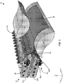
- FIG. 1 is a perspective illustration of a system 10 that includes an extrusion die 12 and a calender formed of cooperating rollers 14 and 16.
- Extrusion die receives molten thermoplastic material, for example from an upstream feed block not illustrated, and extrudes the thermoplastic material into a sheet 18.
- Extrusion die 12 is formed of a first die body portion 20A carrying a first lip body 22A and a second die body portion 20B carrying a second lip body 22B.
- First die body portion 20A is connected to first lip body 22A with a plurality of fasteners 24 positioned at spaced intervals along the length of extrusion die 12 (in the Y-direction indicated on FIG. 1 ).
- extrusion die 12 also has a fastener tension adjustment assembly 26 that is operable to adjust the tension on fasteners 24 and, correspondingly, the amount of force holding first lip body 22A to first die body portion 20A.
- extrusion die 12 includes first lip body 22A and second lip body 22B forming the outlet orifice.
- First lip body 22A is connectable to first die body portion 20A to provide a first die lip bounding one side of the outlet orifice of the extrusion die.
- Second lip body 22B is connectable to second die body portion 20B to provide a second die lip bounding an opposite side of the outlet orifice of the extrusion die.
- one of first lip body 22A and second lip body 22B can be made integral with the corresponding die body portion such that the lip body is not a physically separate structure from the die body.
- the extrusion die can process any desired types of thermoplastic materials to form sheet 18.
- Example polymeric materials that may be extruded using extrusion die 12 include, but are not limited to, polyethylene (e.g., high-density, low-density, linear low-density), polypropylene, polyvinyl chloride, polystyrene, polyethylene terephthalate, ethylene vinyl alcohol, polyvinyl alcohol, polyvinylidene chloride, polyamides, polycarbonates, cellulosics, and combinations thereof.
- two or more different types of thermoplastic materials are fed in to the inlet of the extrusion die to produce a multilayer sheet 18.
- the resulting multilayer film is composed of multiple individual layers stacked one on top of another and adhered together, with at least one individual layer having a different composition than at least one other individual layer in the film.
- extrusion die 12 includes fastener tension adjustment assembly 26 that is operable to adjust the tension on fasteners 24, which mechanically couple first lip body 22A to first die body portion 20A. Additional details about fastener tension adjustment assembly 26 are provided in connection with FIGS. 3-6 .
- second die body portion 20B is also connected to second lip body 22B with a plurality of fasteners 28 positioned at spaced intervals along the length of extrusion die 12.
- a second tension adjustment assembly 30 is provided to adjust the tension on fasteners 28 and, correspondingly, the amount of force holding second lip body 22B to second die body portion 20B.
- Fasteners 28 and second tension adjustment assembly 30 can have the same configuration as fasteners 24 and fastener tension adjustment assembly 26.
- extrusion die 12 does not include second tension adjustment assembly 30 but instead only has a single tension adjustment assembly attaching one lip body (e.g., first lip body 22A or second lip body 22B) to a corresponding die body portion (e.g., first die body portion 20A or second die body portion 20B).
- Extrusion die 12 also includes first lip body 22A, second lip body 22B.
- First lip body 22A has a first lip face 38A.
- Second lip body 22B has a second lip face 38B.
- First lip face 38A and second lip face 38B provide surfaces downstream of first flow channel face 34A and second flow channel face 34B that face flow channel 32 and bound the flow channel. When polymer is flowing through flow channel 32, the polymer can flow adjacent to and in contact with first lip face 38A and second lip face 38B.
- extrusion die 12 is illustrated as having a land channel body 40 having a land channel face 42 positioned between second flow channel face 34B and second lip face 38B.
- land channel body 40 can move independently of second die body portion 20B and second lip body 22B, allowing the length of the land channel in extrusion die 12 to be adjusted.
- extrusion die 12 does not have land channel body 40 or an adjustable land channel length, and the disclosure is not limited in this respect.
- first lip body 22A is illustrated as being a flexible lip body while second lip body 22B is illustrated as having an inflexible lip body.
- the flexible lip body includes a hinge 44, which is defined in part by a recess 46. Hinge 44 allows movement of the flexible lip body relative to first die body portion 20A. A biasing member can push against the cantilevered end of the flexible lip body to cause the lip to flex at hinge 44 (while the upstream end of the lip body does not flex).
- second lip body 22B may also be configured as a flexible lip body or first lip body 22A may be configured as an inflexible lip body.
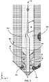
- First lip body 22A and second lip body 22B form an outlet orifice 48 of flow channel 32 between the two bodies.
- Molten polymer is received at an inlet of flow channel 32, conveyed along the length of the flow channel (in the Z-direction indicated on FIG. 2 ) through the extrusion die, and discharged from the extrusion die via outlet orifice 48.
- Flow channel 32 is bounded on one side (in the X- direction indicated on FIG. 2 ) by first flow channel face 34A and first lip face 38A.
- Flow channel 32 is bounded on an opposite side by second flow channel face 34B, land channel face 42, and second lip face 38B.
- Flow channel 32 bounded in that the different surfaces delimit the cavity inside of extrusion die 12 forming the flow channel.
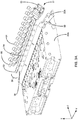
- FIGS. 3A and 3B are exploded perspective front and back views, respectively, of an example configuration of fastener tension adjustment assembly 26 that is used in system 10 of FIG. 1 .
- the different components of fastener tension adjustment assembly 26 are illustrated as being separated from but connectable to each other so as to provide adjustable tension control between first die body portion 20A and first lip body 22A.
- first lip body 22A is positioned on a downstream face 50 (in the direction of polymer flow) of first die body portion 20A.
- first lip body 22A is shown as a physically separate structure from first die body portion 20A that can be removably connected to the die body portion using a plurality of fasteners 24.
- a force can be generated by elongated body 52 and applied to fasteners 24 by moving grooves 54 and cam members 56 relative to each other, causing elongated body 52 to bear against fasteners 24 with greater or lesser force depending on the relative position of the cam members within the grooves.
- grooves 54 may be deeper on one end and shallower on the opposite end. As cam members 56 move from the deeper end to the shallower end of the groove in such a configuration, the cam members push elongated body 52 away from first lip body 22A, increasing the amount of force applied by the elongated body to fasteners 24. Conversely, as cam members 56 move from the shallower end to the deeper end of the groove, elongated body 52 moves towards first lip body 22A, decreasing the amount of force applied by the elongated body to fasteners 24.
- elongated body 52 is in direct contact with each of the plurality of fasteners 24 such that the elongated body presses directly against the fasteners (e.g., heads of the fasteners).
- elongated body 52 contacts an intermediate structure positioned between the elongated body and the plurality of fasteners. In this latter configuration, elongated body 52 can press indirectly against the plurality of fasteners 24 by pressing against the intermediate structure which, in turn, transmits force from elongated body 52 to the fasteners.
- fastener tension adjustment assembly 26 is illustrated as including a plurality of fastener engagement members 58.
- Each of the plurality of fastener engagement members 58 corresponds to one of the plurality of fasteners 24.
- Each fastener engagement member 58 has a hole through which a fastener 24 is inserted.
- Each fastener engagement member 58 can engage with a head or other enlarged cross-sectional region of a fastener.
- each fastener engagement member 58 is in contact with elongated body 52. Accordingly, as elongated body 52 moves towards or away from first lip body 22A, the elongated body bears against the plurality of fastener engagement members 58 with lesser or greater force. In turn, this causes the amount of force pushing on fasteners 24 to decrease or increase.
- fastener tension adjustment assembly 26 includes an actuator 57.
- Actuator 57 is illustrated as a single-point actuator that is operable to translate elongated body 52 laterally (in the positive and negative Y-direction indicated on FIG. 3A ).
- Actuator can be operated by rotating an actuator body 59, thereby forcing a rod coupled to elongated body 52 to move axially toward or away from the actuator body.
- elongated body 52 translates axially toward or away from the actuator body 59, it also moves toward or away from first lip body 22A.
- Other actuator configurations can be used, as will be appreciated by those of ordinary skill in the art.
- head 70 may have a cross-sectional area larger than fastener hole 62 in fastener engagement member 58 and fastener hole 64 in first lip body 22A.
- Shaft 72 can be threaded such that it threading engages with a fastener opening 74 in first die body portion 20A.
- first lip body 22A To secure first lip body 22A to first die body portion 20A in the illustrated example, the distal end of fastener 24 formed by shaft 72 is inserted through fastener hole 62 in fastener engagement member 58 and fastener hole 64 in first lip body 22A. The distal end of fastener 24 is then advanced into fastener opening 74 in first die body portion 20A by turning the threaded shaft in the opening. As fastener 24 advances distally into fastener opening 74, the proximal end of the fastener formed by head 70 presses against fastener engagement member 58. The twisting force or torque applied to fastener 24 causes head 70 to bear against fastener engagement member 58 and, in turn, first lip body 22A with increasing force.
- fastener tension adjustment assembly 26 moves towards or away from first lip body 22A.
- grooves 54 on elongated body 52 may be deeper on one end and shallower on the opposite end.
- cam member 56 moves from the deeper end to the shallower end of the groove. This causes cam member 56 of fastener tension adjustment assembly 26 to push elongated body 52 away from first lip body 22A.
- elongated body 52 presses against fastener engagement member 58, which further pushes against head 70 of fastener 24.
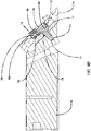
- FIGS. 5A and 5B are cross-sectional views of elongated body 52 showing an example configuration of groove 54.
- groove 54 has a first end 76, a second end 78, and a bottom surface 80.
- Groove 54 has a length 82 and a depth 84.
- the second end 78 of groove 54 is deeper (extends farther into elongated body 52) than the first end 76 of the groove. Accordingly, the bottom surface 80 of groove 54 is angled from the first end 76 to the second end 78.
- FIG. 5A illustrates elongated body 52 moved to a first lateral position (e.g., in the positive Y-direction indicated on FIG. 3 ) with cam member 56 positioned in the second end 78 of groove 54. Since groove 54 is deeper at second end 78, elongated body 52 is moved towards first lip body 22A and, in the illustrated example, is in contact with first lip body 22A.
- FIG. 5B illustrates elongated body 52 moved to a second lateral position (e.g., in the negative Y-direction indicated on FIG. 3 ) with cam member 56 positioned in the first end 76 of groove 54. Since groove 54 is shallower at first end 76, elongated body 52 is moved away from first lip body 22A and, in the illustrated example, creates a small gap between the elongated body and first lip body 22A.
- the bottom surface 80 of groove 54 has a constant slope such that there is a continuous angle or taper from the first end 76 to the second end 78.
- the amount of force applied by fastener tension adjustment assembly 26 progressively and continuously increases as cam member 56 translates in one direction within groove 54 and progressively and continuously decreases as cam member 56 translates in the opposite direction.
- the bottom surface 80 of groove 54 has a discontinuously variable depth across its length 82.
- the bottom surface 80 of groove 54 can have multiple shallow regions interspaced by regions of deeper depth. The regions of shallower depth can each have a different depth, providing discrete positions into which cam member 56 is moved during operation.
- the groove translates relative to cam member 56 to move fastener tension adjustment assembly 26 toward and away from first lip body 22A in the FIGS. 5A and 5B . That is, due to the inclined (or "ramped") configuration of groove 54, the resulting camming and/or rolling action of cam member 56 moves elongated body 52 towards and away from first lip body 22A. In this configuration, cam member 56 does not move relative to first lip body 22A. Rather, cam member 56 remains stationary while elongated body 52 translates laterally relative to the cam member, causing the elongated body to also move relative to first lip body 22A (e.g., into and out of contact with first lip body 22A).
- fastener tension adjustment assembly 26 is described as being configured to move toward and away from first lip body 22A, it should be appreciated that the entire assembly need not move relative to the lip body. Instead, one or more components of fastener tension adjustment assembly 26 can move toward and away from first lip body 22A while one or other components of the assembly remain stationary.
- Fastener tension adjustment assembly 26 is illustrated in FIGS. 4A-4B and 5A-5B as having cam member 56 positioned between elongated body 52 and first lip body 22A.
- cam member 56 can be positioned between elongated body 52 and fastener engagement member 58 such that groove 54 opens outwardly toward the fastener engagement member.
- cam member 56 moves towards and away from first lip body 22A (by translating along the inclined bottom surface 80 of groove 54) while elongated body 52 translates laterally relative to the cam member.
- Elongated body does not move towards and away from first lip body 22A in such a configuration.
- cam member 56 can be located between elongated body 52 and first lip body 22A and/or between elongated body 52 and fastener engagement member 58.
- cam member 56 is any member that provides a camming action with elongated body 52, e.g., converting rotary motion into linear motion.
- cam member 56 is a sphere, such as a ball bearing that is received in groove 54.
- the bottom surface of groove 54 defines an elongated, inclined track that rides on the sphere received in that groove during relative movement of elongated body 52 and cam member 56.
- cam member 56 can be a cylinder (e.g., pin) against which elongated body 52 cams (and/or rolls) during relative movement.
- fastener tension adjustment assembly 26 does not include cam members 56. Rather, in these configurations, camming action can be provided by oppositely tapered wedge surfaces on first lip body 22A and elongated body 52.
- cam member 56 is illustrated as being physically separate from and insertable into elongated body 52 and first lip body 22A, it should be appreciated that cam member 56 need not have such a configuration. Instead, cam member 56 can be permanently formed in first lip body 22A and/or elongated body 52 (e.g., as a bump or protrusion extending outwardly from such structure) with a groove formed in the corresponding structure.
- fastener tension adjustment assembly 26 can include fastener engagement member 58.
- FIG. 6 is an exploded view of a portion of fastener tension adjustment assembly 26 from FIG. 4A showing a configuration of fastener engagement member 58.
- fastener tension engagement member 58 has a body 86 having a fastener hole 88 extending therethrough and a cantilevered arm 90.
- first lip body 22A has an external face 92 forming a recessed channel 94.
- the recessed channel has a bottom surface 96 with a fastener opening 98 extending therethrough.
- the cantilevered arm 90 of fastener engagement member 58 extends over a portion of recessed channel 94 to form a pocket 100 between the bottom surface 96 of the channel and the cantilevered arm.
- Elongated body 52 is positioned in pocket 100 and is in contact with a bottom surface of cantilevered arm 90.
- fastener tension adjustment assembly 26 applied force directly to fastener 24 (e.g., a head of the fastener) without utilizing fastener engagement member 58.
- the amount of force applied by fastener tension adjustment assembly 26 can be adjusted by adjusting the configuration of groove 54 and/or cam member 56.
- the amount of force applied by fastener tension adjustment assembly 26 when cam member 56 is at the shallowest location in groove 54 can be increased by decreasing the depth of the groove at that location and/or increasing the size of cam member.
- the amount of force applied by fastener tension adjustment assembly 26 when cam member 56 is at the deepest location in groove 54 can be decreased by increasing the depth of the groove at that location and/or decreasing the size of cam member 56.
- fastener tension adjustment assembly 26 is configured to increase the amount of torque on each of the plurality of fasteners by at least 50 foot-pounds when the assembly is actuated from a disengaged position in which cam member 56 is at the shallowest location in groove 54 to an engaged position in which cam member 56 is at the deepest location in groove 54.
- Such a configuration can be achieved by having the depth of groove 54 increase by 0.002" over a length of 1.25", which can adjust the torque on fasteners 24 from 30 foot-pounds when the assembly is in a disengaged position and cam member 56 is at the shallowest location of the groove to 90 foot-pounds when the assembly is in an engaged position and the cam member is at the deepest location in the groove.
- an operator may initially insert each of the plurality of fasteners 24 through corresponding fastener holes 62, 64 in fastener engagement member 58 and first lip body 22A, advancing the distal ends of the fasteners into corresponding fastener openings 74 in first die body portion 74.
- the operator can tighten each fastener individually to a threshold amount of torque.
- the threshold amount of torque can be the same for each of the plurality of fasteners or may be different for different fasteners. In some applications, the threshold amount of torque is at least 10 foot-pounds, such as at least 25 foot-pounds.
- fastener tension adjustment assembly 26 can engage fastener tension adjustment assembly 26 to simultaneously increase the amount of force (e.g., torque) applied by each of the plurality of fasteners holding first lip body 22A to first die body portion 20A.
- the operator can actuate fastener tension adjustment assembly 26, causing elongated body 52 to slide laterally (e.g., transversely) and parallel to first lip body 22A.
- elongated body 52 slides parallel to first lip body 22A, cam members 56 translate within corresponding grooves 54, forcing elongated body 52 orthogonally away from the bottom surface 96 of the lip body.
- elongated body 52 moves bi-directionally, both parallel to and away from first lip body 22A.
- the elongated body 52 moves orthogonally away from first lip body 22A, the elongated body pushes against fastener engagement members 58 (or, in other configurations, directly against fasteners 24), pushing the fasteners axially outward from the holes in which they inserted. This increases the amount of torque / force on the fasteners.
- fastener tension adjustment assembly 26 is operatively connected to a plurality of fasteners 24, a single adjustment on the assembly to actuate the assembly can simultaneously adjust the amount of force applied to all fasteners. For example, actuating fastener tension adjustment assembly 26 can adjust the amount of force applied to each of the plurality of fasteners 24 at the same time and/or at the same rate.
- fastener tension adjustment assembly 26 can adjust the force applied to each of the plurality of fastener 24 by the same amount, the assembly is not limited to such a configuration.
- the amount of force applied to any one fastener can be controlled by controlling the configuration (e.g., size, depth) of the groove 54 and cam member 56 associated with each particular fastener.
- fastener tension adjustment assembly 26 is used to simultaneously adjust the amount of force applied to each of the plurality of fasteners, with the amount of force being applied (by assembly 26) to one fastener being different than the amount of force applied to at least one other fastener.
- extrusion die 12 can be operated while the plurality of fasteners 24 are held under an elevated amount of force provided by fastener tension adjustment assembly 26.
- fastener tension adjustment assembly 26 For example, after actuating fastener tension adjustment assembly 26 to cause the plurality of cam members 56 to translate to the shallowest location in their corresponding grooves 54, the cam members can be held in that position while molten polymer is run through extrusion die 12 to produce sheet 18 ( FIG. 1 ).
- fastener tension adjustment assembly 26 has been described herein as being suitable for adjusting an amount of force, or tension, applied on a plurality of fasteners holding a lip body to a die body portion, such an assembly can be used in other applications both within extrusion dies and outside of the extrusion die industry.
- fastener tension adjustment assembly 26 can be used to adjust the amount of tension applied on the body bolts holding a first body die portion to a second body die portion.
- Fastener tension adjustment assembly 26 can be operatively connected to each of a plurality of bolts connecting the first die body portion to the second die body portion and used to simultaneously adjust an amount of force applied to each of said plurality of fasteners.
Landscapes
- Engineering & Computer Science (AREA)
- Mechanical Engineering (AREA)
- Manufacturing & Machinery (AREA)
- Extrusion Moulding Of Plastics Or The Like (AREA)
Claims (15)
- Filière d'extrusion (12) comprenant un corps de filière, un corps de rebord (22A, 22B), une pluralité d'éléments de fixation (24), un ensemble de réglage de tension d'élément de fixation (26) et un canal d'écoulement (32) se terminant dans un orifice de sortie (48) ;
ledit corps de filière incluant une première portion de corps de filière (20A) et une seconde portion de corps de filière (20B) formant le canal d'écoulement (32) entre elles ;
ledit corps de rebord (22A, 22B) étant physiquement séparé de et relié à l'une de ladite première portion de corps de filière (20A) et de ladite seconde portion de corps de filière (20B) par ladite pluralité d'éléments de fixation (24) et formant un côté de l'orifice de sortie (48) ; et
l'ensemble de réglage de tension d'élément de fixation (26) comprenant un corps allongé (52) fonctionnellement relié à chacun de ladite pluralité d'éléments de fixation (24),
caractérisée en ce que ledit ensemble de réglage de tension d'élément de fixation (26) peut se rapprocher ou s'éloigner dudit corps de rebord (22A, 22B), réglant ainsi simultanément une quantité de force appliquée à chacun de ladite pluralité d'éléments de fixation (24). - Filière d'extrusion selon la revendication 1, dans laquelle ledit corps allongé (52) comprend une barre coulissante (52) qui applique une force à chacun de ladite pluralité d'éléments de fixation (24), ladite barre coulissante est configurée pour coulisser dans une direction latérale par rapport à ladite pluralité d'éléments de fixation (24) tout en se rapprochant ou en s'éloignant dudit corps de rebord, et la force appliquée par ladite barre coulissante à chacun de ladite pluralité d'éléments de fixation (24) est appliquée dans une direction orthogonale à la direction latérale.
- Filière d'extrusion selon la revendication 2, dans laquelle ladite barre coulissante est configurée pour coulisser depuis une première position latérale vers une seconde position latérale, la force appliquée par ladite barre coulissante à chacun de ladite pluralité d'éléments de fixation (24) augmente progressivement à mesure que ladite barre coulissante coulisse depuis la première position latérale vers la seconde position latérale et diminue progressivement à mesure que ladite barre coulissante coulisse depuis la seconde position latérale vers la première position latérale.
- Filière d'extrusion selon la revendication 1, dans laquelle chacun de ladite pluralité d'éléments de fixation (24) comporte une tête (70) et un arbre (72), et ledit corps allongé (52) s'appuie contre ladite tête (70) de chacun de ladite pluralité d'éléments de fixation (24) et/ou
dans laquelle chacun de ladite pluralité d'éléments de fixation (24) comprend un boulon ayant une tête (70) et un arbre (72), ledit arbre (72) s'étend à travers ledit corps de rebord et dans ladite une de ladite première portion de corps de filière (20A) et de ladite seconde portion de corps de filière (20B) à laquelle ledit corps de rebord est relié. - Filière d'extrusion selon la revendication 4, comprenant en outre une pluralité d'éléments de mise en prise d'élément de fixation (58), chacun de ladite pluralité d'éléments de mise en prise d'élément de fixation (58) étant positionné entre ladite tête (70) dudit boulon et ledit corps de rebord, dans laquelle ledit ensemble de réglage de tension d'élément de fixation (26) appuie sur ladite pluralité d'éléments de mise en prise d'élément de fixation (58) ;
et dans laquelle de préférence chacun de ladite pluralité d'éléments de mise en prise d'élément de fixation (58) comprend un corps (86) ayant un trou pour élément de fixation (88) s'étendant à travers celui-ci et un bras en porte-à-faux (90), et ledit ensemble de réglage de tension d'élément de fixation (26) appui sur ledit bras en porte-à-faux (90) avec une force croissante à mesure que ledit ensemble de réglage de tension d'élément de fixation (26) s'éloigne dudit corps de rebord et une force décroissante à mesure que ledit ensemble de réglage de tension d'élément de fixation (26) se rapproche dudit corps de rebord ;
et dans laquelle de préférence ledit corps de rebord comporte une face externe (92) ayant un canal évidé (94) avec une surface de fond (96) ayant une pluralité d'ouvertures pour élément de fixation (98) à travers celle-ci, ledit bras en porte-à-faux (90) s'étend sur une portion dudit canal évidé (94) pour former une poche (100) entre ladite surface de fond (96) et ledit bras en porte-à-faux (90), et ledit corps allongé (52) est positionné dans ladite poche (100). - Filière d'extrusion selon la revendication 5, dans laquelle ledit ensemble de réglage de tension d'élément de fixation (26) comprend en outre une pluralité d'éléments de fixation de came (56) situés entre l'un dudit corps allongé (52) et ledit corps de rebord, et ledit corps allongé (52) et ladite pluralité d'éléments de mise en prise d'élément de fixation (58) ;
dans laquelle de préférence chacun de ladite pluralité d'éléments de fixation de came (56) comprend une sphère, ledit corps allongé (52) comprend une pluralité de surfaces inclinées, et chacune de ladite pluralité de surfaces inclinées s'étend sur un de ladite pluralité d'éléments de came (56) correspondant à mesure que ledit ensemble de réglage de tension d'élément de fixation (26) se rapproche et s'éloigne dudit corps de rebord. - Filière d'extrusion selon la revendication 6, dans laquelle ledit corps allongé (52) comprend une pluralité de rainures (54), chacune desdites rainures (54) comporte une première extrémité (76) et une seconde extrémité (78), ladite seconde extrémité (78) de chaque rainure (54) étant plus profonde que ladite première extrémité (76), de telle sorte que lesdites surfaces inclinées sont des fonds desdites rainures (54), chacun de ladite pluralité d'éléments de came (56) étant reçu dans une de ladite pluralité de rainures (54) respective.
- Filière d'extrusion selon la revendication 1, dans laquelle ledit ensemble de réglage de tension d'élément de fixation (26) comprend en outre un actionneur (57) configuré pour rapprocher et éloigner ledit ensemble de réglage de tension d'élément de fixation (26) dudit corps de rebord.
- Filière d'extrusion selon la revendication 8, dans laquelle
ledit ensemble de réglage de tension d'élément de fixation (26) comprend en outre une pluralité de sphères situées entre ledit corps de rebord et ledit corps allongé (52),
ledit corps allongé (52) comporte une pluralité de rainures (54) correspondantes dans lesquelles ladite pluralité de sphères sont positionnées,
chacune de ladite pluralité de rainures (54) correspondantes a une longueur (82) et une profondeur (84), ladite profondeur (84) diminuant à travers ladite longueur (82), et
ledit mécanisme de réglage est configuré pour déplacer ledit corps allongé (52) par rapport audit corps de rebord, amenant ainsi ladite pluralité de sphères à translater dans ladite pluralité de rainures (54) correspondantes. - Filière d'extrusion selon la revendication 1, dans laquelle ledit corps de rebord est un premier corps de rebord (22A) relié à ladite première portion de corps de filière (20A), et comprenant en outre un second corps de rebord (22B) relié à ladite seconde portion de corps de filière (20B), ledit second corps de rebord (22B) formant un côté de l'orifice de sortie (48) opposé audit premier corps de rebord (22A).
- Filière d'extrusion selon la revendication 10, dans laquelle ledit orifice de sortie (48) a une largeur, et ledit premier corps de rebord (22A) est configuré pour se déplacer afin de régler la largeur.
- Procédé de réglage d'une quantité de force appliquée à une pluralité d'éléments de fixation (24) reliant un corps de rebord (22A, 22B) à une portion de corps de filière (20A, 20B) sur une filière d'extrusion (12) en utilisant un ensemble de réglage de tension d'élément de fixation (26), le procédé comprenant :l'actionnement dudit ensemble de réglage de tension d'élément de fixation (26) et ainsi le fait d'amener ledit ensemble de réglage de tension d'élément de fixation (26) à s'éloigner dudit corps de rebord, eten réponse à l'éloignement dudit ensemble de réglage de tension d'élément de fixation (26) dudit corps de rebord, l'augmentation simultanée d'une quantité de force appliquée par ledit ensemble de réglage de tension d'élément de fixation (26) sur chacun de ladite pluralité d'éléments de fixation (24),dans lequel ledit corps de rebord est physiquement séparé de ladite portion de corps de filière et peut y être attaché.
- Procédé selon la revendication 12, dans lequel ledit corps de rebord comporte une pluralité de trous pour élément de fixation (62) et ledit corps de filière comporte une pluralité d'ouvertures pour élément de fixation (74), et comprenant en outre, avant l'actionnement dudit ensemble de réglage de tension d'élément de fixation (26), l'introduction de chacun de ladite pluralité d'éléments de fixation (24) à travers un de ladite pluralité de trous pour élément de fixation (62) correspondant et dans une de ladite pluralité d'ouvertures pour élément de fixation (74) correspondante, et le réglage d'une force appliquée par chacun de ladite pluralité d'éléments de fixation (24) sur une base d'élément de fixation par élément de fixation,
l'actionnement dudit ensemble de réglage de tension d'élément de fixation (26) et ainsi le fait d'amener ledit ensemble de réglage de tension d'élément de fixation (26) à se rapprocher dudit corps de rebord, et
en réponse à l'éloignement dudit ensemble de réglage de tension d'élément de fixation (26) dudit corps de rebord, la diminution simultanée de la quantité de force appliquée par ledit ensemble de réglage de tension d'élément de fixation (26) sur chacun de ladite pluralité d'éléments de fixation (24). - Procédé selon la revendication 13, dans lequel ladite filière d'extrusion (12) comporte un orifice de sortie (48) ayant une largeur, et comprenant en outre, à la suite de l'actionnement dudit ensemble de réglage de tension d'élément de fixation (26) et ainsi du fait d'avoir amené ledit ensemble de réglage de tension d'élément de fixation (26) à se rapprocher dudit corps de rebord, le déplacement dudit corps de rebord par rapport à ladite portion de corps de filière et ainsi le réglage de ladite largeur.
- Procédé selon la revendication 12, dans lequel ledit ensemble de réglage de tension d'élément de fixation (26) comprend un corps allongé (52) ayant une pluralité de rainures (54) et une pluralité de sphères, chacune de ladite pluralité de rainures (54) a une première extrémité (76) et une seconde extrémité (78), ladite seconde extrémité (78) de chaque rainure (54) étant plus profonde que ladite première extrémité (76), et le fait d'amener ledit ensemble de réglage de tension d'élément de fixation (26) à s'éloigner dudit corps de rebord comprend le déplacement de ladite pluralité de sphères depuis ladite seconde extrémité (78) de chaque rainure (54) vers ladite première extrémité (76).
Applications Claiming Priority (1)
| Application Number | Priority Date | Filing Date | Title |
|---|---|---|---|
| US14/660,386 US9694530B2 (en) | 2015-03-17 | 2015-03-17 | Extrusion die tension adjuster and method of using same |
Publications (2)
| Publication Number | Publication Date |
|---|---|
| EP3069845A1 EP3069845A1 (fr) | 2016-09-21 |
| EP3069845B1 true EP3069845B1 (fr) | 2019-06-19 |
Family
ID=55661186
Family Applications (1)
| Application Number | Title | Priority Date | Filing Date |
|---|---|---|---|
| EP16160677.7A Active EP3069845B1 (fr) | 2015-03-17 | 2016-03-16 | Dispositif de réglage de tension de filière d'extrusion et son procédé d'utilisation |
Country Status (4)
| Country | Link |
|---|---|
| US (2) | US9694530B2 (fr) |
| EP (1) | EP3069845B1 (fr) |
| JP (1) | JP2016172444A (fr) |
| CN (1) | CN105984108A (fr) |
Families Citing this family (4)
| Publication number | Priority date | Publication date | Assignee | Title |
|---|---|---|---|---|
| US9815237B2 (en) | 2015-02-20 | 2017-11-14 | Nordson Corporation | System for adjusting the land channel length on an extrusion die |
| US10272609B2 (en) * | 2016-09-26 | 2019-04-30 | Nordson Corporation | Extrusion die having thermally responsive lip adjustment assembly |
| DE102019127777A1 (de) * | 2019-10-15 | 2021-04-15 | Reifenhäuser GmbH & Co. KG Maschinenfabrik | Anlage zum Herstellen einer koextrudierten Mehrschichtenfolie, Vorrichtung zum Koextrudieren eines mehrlagigen Koextrusionsverbundes und Verfahren zum Koextrudieren sowie Verfahren zum Betreiben einer diesbezüglichen Anlage und/oder Vorrichtung |
| CN112873818B (zh) * | 2020-12-24 | 2022-11-22 | 重庆瑞霆塑胶有限公司 | 用于共挤吹塑机的压膜机构 |
Citations (3)
| Publication number | Priority date | Publication date | Assignee | Title |
|---|---|---|---|---|
| GB2162119A (en) * | 1984-07-28 | 1986-01-29 | Reifenhaeuser Masch | Extrusion moulding tool for synthetic thermoplastic materials |
| US8702414B1 (en) * | 2011-05-20 | 2014-04-22 | Allied Dies, Inc. | Lip adjustment push system |
| US9302420B1 (en) * | 2010-11-23 | 2016-04-05 | Douglas Darrow | Die having linear bearing array |
Family Cites Families (19)
| Publication number | Priority date | Publication date | Assignee | Title |
|---|---|---|---|---|
| US2963741A (en) | 1956-01-26 | 1960-12-13 | Dow Chemical Co | Adjustable extrusion die |
| US3382537A (en) | 1966-03-21 | 1968-05-14 | Dow Chemical Co | Adjustable extrusion die |
| US3829274A (en) | 1972-10-19 | 1974-08-13 | Beloit Corp | Interchangeable die lips for extrusion die and independently adjustable deckles therefor |
| US3813204A (en) | 1973-02-28 | 1974-05-28 | G K Syst Inc | Lip adjustment for extrusion die |
| DE3628974C1 (de) | 1986-08-26 | 1988-02-25 | Schmidt Erwepa Maschf | Breitschlitzduese zum Extrudieren von Thermoplasten |
| DE8813801U1 (de) | 1988-11-04 | 1988-12-22 | Röhm GmbH, 6100 Darmstadt | Verstellbare Extrusionsschlitzdüse |
| JPH0494423U (fr) | 1990-12-26 | 1992-08-17 | ||
| US5639305A (en) | 1994-04-29 | 1997-06-17 | Minnesota Mining And Manufacturing Company | Die coating method and apparatus |
| JPH08112852A (ja) | 1994-10-17 | 1996-05-07 | Sumitomo Heavy Ind Ltd | 層分布自動調整システム |
| JP2000505367A (ja) | 1996-01-31 | 2000-05-09 | ブラック・クローソン・カンパニー・インコーポレーテッド | スライド型のダイリップを備える押出ダイ |
| US6017207A (en) * | 1996-09-24 | 2000-01-25 | Cloeren Incorporated | Apparatus for adjusting die lip gap |
| US6287105B1 (en) * | 1997-06-13 | 2001-09-11 | Cloeren Incorporated | Controlling assembly for adjusting lip gap |
| US7296991B2 (en) | 2004-12-10 | 2007-11-20 | Irwin Jere F | Adjustable extruder die assembly die lip adjustment apparatus |
| US8858211B2 (en) | 2011-01-31 | 2014-10-14 | Premier Dies Corporation | Liquid coating die |
| US8777605B2 (en) | 2011-04-05 | 2014-07-15 | Nordson Extrusion Dies Industries, Llc | Deckle technology |
| DE102011076163A1 (de) * | 2011-05-20 | 2012-11-22 | Trocellen Gmbh | Verfahren und Vorrichtung zur Extrusion einer Bahn aus thermoplastischem Kunststoff |
| US9149967B2 (en) | 2011-11-16 | 2015-10-06 | Nordson Corporation | Extrusion dies with internal and/or external deckles |
| US9808980B2 (en) | 2014-07-29 | 2017-11-07 | Nordson Corporation | Coextrusion feedblock, coextrusion profiling insert assembly, and methods of operation |
| US9815237B2 (en) | 2015-02-20 | 2017-11-14 | Nordson Corporation | System for adjusting the land channel length on an extrusion die |
-
2015
- 2015-03-17 US US14/660,386 patent/US9694530B2/en not_active Expired - Fee Related
-
2016
- 2016-03-16 EP EP16160677.7A patent/EP3069845B1/fr active Active
- 2016-03-17 JP JP2016053904A patent/JP2016172444A/ja not_active Ceased
- 2016-03-17 CN CN201610153822.2A patent/CN105984108A/zh active Pending
-
2017
- 2017-06-07 US US15/616,196 patent/US9925709B2/en not_active Expired - Fee Related
Patent Citations (3)
| Publication number | Priority date | Publication date | Assignee | Title |
|---|---|---|---|---|
| GB2162119A (en) * | 1984-07-28 | 1986-01-29 | Reifenhaeuser Masch | Extrusion moulding tool for synthetic thermoplastic materials |
| US9302420B1 (en) * | 2010-11-23 | 2016-04-05 | Douglas Darrow | Die having linear bearing array |
| US8702414B1 (en) * | 2011-05-20 | 2014-04-22 | Allied Dies, Inc. | Lip adjustment push system |
Also Published As
| Publication number | Publication date |
|---|---|
| US9925709B2 (en) | 2018-03-27 |
| EP3069845A1 (fr) | 2016-09-21 |
| US20160271855A1 (en) | 2016-09-22 |
| US9694530B2 (en) | 2017-07-04 |
| US20170282435A1 (en) | 2017-10-05 |
| CN105984108A (zh) | 2016-10-05 |
| JP2016172444A (ja) | 2016-09-29 |
Similar Documents
| Publication | Publication Date | Title |
|---|---|---|
| US9925709B2 (en) | Extrusion die tension adjuster and method of using same | |
| US10821643B2 (en) | System and method for adjusting the land channel length on an extrusion die | |
| US9808980B2 (en) | Coextrusion feedblock, coextrusion profiling insert assembly, and methods of operation | |
| US7435000B2 (en) | Guide carriage of a linear rolling bearing | |
| US5273420A (en) | Extrusion die for thermoplastic webs | |
| US11110632B2 (en) | Roll-molding | |
| US8268213B2 (en) | Flexible lip extruder, and methods of extruding material | |
| KR102308263B1 (ko) | 압출 성형용 플랫 다이 및 필름 성형 방법 | |
| EP3703927B1 (fr) | Ensemble moule modulaire | |
| US11045991B2 (en) | Dual stage flex lip for an extrusion die | |
| JP4716879B2 (ja) | 押出成形用tダイ | |
| US20180326642A1 (en) | Sheet extrusion die | |
| JP6538327B2 (ja) | デッケルシステムを備える押出ダイ及びその使用方法 | |
| US20140137621A1 (en) | Apparatus and method for producing shear deformation | |
| US10399266B1 (en) | Die having linear bearing array | |
| DE10331325A1 (de) | Auftragsvorrichtung mit verstellbarer Auftragsbreite |
Legal Events
| Date | Code | Title | Description |
|---|---|---|---|
| PUAI | Public reference made under article 153(3) epc to a published international application that has entered the european phase |
Free format text: ORIGINAL CODE: 0009012 |
|
| AK | Designated contracting states |
Kind code of ref document: A1 Designated state(s): AL AT BE BG CH CY CZ DE DK EE ES FI FR GB GR HR HU IE IS IT LI LT LU LV MC MK MT NL NO PL PT RO RS SE SI SK SM TR |
|
| AX | Request for extension of the european patent |
Extension state: BA ME |
|
| STAA | Information on the status of an ep patent application or granted ep patent |
Free format text: STATUS: REQUEST FOR EXAMINATION WAS MADE |
|
| STAA | Information on the status of an ep patent application or granted ep patent |
Free format text: STATUS: EXAMINATION IS IN PROGRESS |
|
| 17P | Request for examination filed |
Effective date: 20170321 |
|
| RBV | Designated contracting states (corrected) |
Designated state(s): AL AT BE BG CH CY CZ DE DK EE ES FI FR GB GR HR HU IE IS IT LI LT LU LV MC MK MT NL NO PL PT RO RS SE SI SK SM TR |
|
| 17Q | First examination report despatched |
Effective date: 20170425 |
|
| GRAP | Despatch of communication of intention to grant a patent |
Free format text: ORIGINAL CODE: EPIDOSNIGR1 |
|
| STAA | Information on the status of an ep patent application or granted ep patent |
Free format text: STATUS: GRANT OF PATENT IS INTENDED |
|
| RIC1 | Information provided on ipc code assigned before grant |
Ipc: B29C 47/08 20060101ALI20181122BHEP Ipc: B29C 47/92 20060101ALI20181122BHEP Ipc: B29C 47/16 20060101AFI20181122BHEP Ipc: B29C 47/00 20060101ALN20181122BHEP |
|
| RIC1 | Information provided on ipc code assigned before grant |
Ipc: B29C 47/08 20060101ALI20181128BHEP Ipc: B29C 47/00 20060101ALN20181128BHEP Ipc: B29C 47/92 20060101ALI20181128BHEP Ipc: B29C 47/16 20060101AFI20181128BHEP |
|
| INTG | Intention to grant announced |
Effective date: 20181213 |
|
| GRAJ | Information related to disapproval of communication of intention to grant by the applicant or resumption of examination proceedings by the epo deleted |
Free format text: ORIGINAL CODE: EPIDOSDIGR1 |
|
| STAA | Information on the status of an ep patent application or granted ep patent |
Free format text: STATUS: EXAMINATION IS IN PROGRESS |
|
| REG | Reference to a national code |
Ref country code: DE Ref legal event code: R079 Ref document number: 602016015387 Country of ref document: DE Free format text: PREVIOUS MAIN CLASS: B29C0047160000 Ipc: B29C0048305000 |
|
| GRAR | Information related to intention to grant a patent recorded |
Free format text: ORIGINAL CODE: EPIDOSNIGR71 |
|
| GRAS | Grant fee paid |
Free format text: ORIGINAL CODE: EPIDOSNIGR3 |
|
| STAA | Information on the status of an ep patent application or granted ep patent |
Free format text: STATUS: GRANT OF PATENT IS INTENDED |
|
| INTC | Intention to grant announced (deleted) | ||
| GRAA | (expected) grant |
Free format text: ORIGINAL CODE: 0009210 |
|
| STAA | Information on the status of an ep patent application or granted ep patent |
Free format text: STATUS: THE PATENT HAS BEEN GRANTED |
|
| RIC1 | Information provided on ipc code assigned before grant |
Ipc: B29C 48/92 20190101ALI20190412BHEP Ipc: B29C 48/08 20190101ALI20190412BHEP Ipc: B29C 48/25 20190101ALI20190412BHEP Ipc: B29C 48/305 20190101AFI20190412BHEP |
|
| AK | Designated contracting states |
Kind code of ref document: B1 Designated state(s): AL AT BE BG CH CY CZ DE DK EE ES FI FR GB GR HR HU IE IS IT LI LT LU LV MC MK MT NL NO PL PT RO RS SE SI SK SM TR |
|
| INTG | Intention to grant announced |
Effective date: 20190510 |
|
| REG | Reference to a national code |
Ref country code: GB Ref legal event code: FG4D |
|
| REG | Reference to a national code |
Ref country code: CH Ref legal event code: EP |
|
| REG | Reference to a national code |
Ref country code: IE Ref legal event code: FG4D |
|
| REG | Reference to a national code |
Ref country code: DE Ref legal event code: R096 Ref document number: 602016015387 Country of ref document: DE |
|
| REG | Reference to a national code |
Ref country code: AT Ref legal event code: REF Ref document number: 1144905 Country of ref document: AT Kind code of ref document: T Effective date: 20190715 |
|
| REG | Reference to a national code |
Ref country code: NL Ref legal event code: MP Effective date: 20190619 |
|
| PG25 | Lapsed in a contracting state [announced via postgrant information from national office to epo] |
Ref country code: FI Free format text: LAPSE BECAUSE OF FAILURE TO SUBMIT A TRANSLATION OF THE DESCRIPTION OR TO PAY THE FEE WITHIN THE PRESCRIBED TIME-LIMIT Effective date: 20190619 Ref country code: NO Free format text: LAPSE BECAUSE OF FAILURE TO SUBMIT A TRANSLATION OF THE DESCRIPTION OR TO PAY THE FEE WITHIN THE PRESCRIBED TIME-LIMIT Effective date: 20190919 Ref country code: HR Free format text: LAPSE BECAUSE OF FAILURE TO SUBMIT A TRANSLATION OF THE DESCRIPTION OR TO PAY THE FEE WITHIN THE PRESCRIBED TIME-LIMIT Effective date: 20190619 Ref country code: LT Free format text: LAPSE BECAUSE OF FAILURE TO SUBMIT A TRANSLATION OF THE DESCRIPTION OR TO PAY THE FEE WITHIN THE PRESCRIBED TIME-LIMIT Effective date: 20190619 Ref country code: SE Free format text: LAPSE BECAUSE OF FAILURE TO SUBMIT A TRANSLATION OF THE DESCRIPTION OR TO PAY THE FEE WITHIN THE PRESCRIBED TIME-LIMIT Effective date: 20190619 Ref country code: AL Free format text: LAPSE BECAUSE OF FAILURE TO SUBMIT A TRANSLATION OF THE DESCRIPTION OR TO PAY THE FEE WITHIN THE PRESCRIBED TIME-LIMIT Effective date: 20190619 |
|
| REG | Reference to a national code |
Ref country code: LT Ref legal event code: MG4D |
|
| PG25 | Lapsed in a contracting state [announced via postgrant information from national office to epo] |
Ref country code: GR Free format text: LAPSE BECAUSE OF FAILURE TO SUBMIT A TRANSLATION OF THE DESCRIPTION OR TO PAY THE FEE WITHIN THE PRESCRIBED TIME-LIMIT Effective date: 20190920 Ref country code: LV Free format text: LAPSE BECAUSE OF FAILURE TO SUBMIT A TRANSLATION OF THE DESCRIPTION OR TO PAY THE FEE WITHIN THE PRESCRIBED TIME-LIMIT Effective date: 20190619 Ref country code: BG Free format text: LAPSE BECAUSE OF FAILURE TO SUBMIT A TRANSLATION OF THE DESCRIPTION OR TO PAY THE FEE WITHIN THE PRESCRIBED TIME-LIMIT Effective date: 20190919 Ref country code: RS Free format text: LAPSE BECAUSE OF FAILURE TO SUBMIT A TRANSLATION OF THE DESCRIPTION OR TO PAY THE FEE WITHIN THE PRESCRIBED TIME-LIMIT Effective date: 20190619 |
|
| PG25 | Lapsed in a contracting state [announced via postgrant information from national office to epo] |
Ref country code: RO Free format text: LAPSE BECAUSE OF FAILURE TO SUBMIT A TRANSLATION OF THE DESCRIPTION OR TO PAY THE FEE WITHIN THE PRESCRIBED TIME-LIMIT Effective date: 20190619 Ref country code: CZ Free format text: LAPSE BECAUSE OF FAILURE TO SUBMIT A TRANSLATION OF THE DESCRIPTION OR TO PAY THE FEE WITHIN THE PRESCRIBED TIME-LIMIT Effective date: 20190619 Ref country code: SK Free format text: LAPSE BECAUSE OF FAILURE TO SUBMIT A TRANSLATION OF THE DESCRIPTION OR TO PAY THE FEE WITHIN THE PRESCRIBED TIME-LIMIT Effective date: 20190619 Ref country code: NL Free format text: LAPSE BECAUSE OF FAILURE TO SUBMIT A TRANSLATION OF THE DESCRIPTION OR TO PAY THE FEE WITHIN THE PRESCRIBED TIME-LIMIT Effective date: 20190619 Ref country code: PT Free format text: LAPSE BECAUSE OF FAILURE TO SUBMIT A TRANSLATION OF THE DESCRIPTION OR TO PAY THE FEE WITHIN THE PRESCRIBED TIME-LIMIT Effective date: 20191021 Ref country code: EE Free format text: LAPSE BECAUSE OF FAILURE TO SUBMIT A TRANSLATION OF THE DESCRIPTION OR TO PAY THE FEE WITHIN THE PRESCRIBED TIME-LIMIT Effective date: 20190619 |
|
| PG25 | Lapsed in a contracting state [announced via postgrant information from national office to epo] |
Ref country code: ES Free format text: LAPSE BECAUSE OF FAILURE TO SUBMIT A TRANSLATION OF THE DESCRIPTION OR TO PAY THE FEE WITHIN THE PRESCRIBED TIME-LIMIT Effective date: 20190619 Ref country code: SM Free format text: LAPSE BECAUSE OF FAILURE TO SUBMIT A TRANSLATION OF THE DESCRIPTION OR TO PAY THE FEE WITHIN THE PRESCRIBED TIME-LIMIT Effective date: 20190619 Ref country code: IS Free format text: LAPSE BECAUSE OF FAILURE TO SUBMIT A TRANSLATION OF THE DESCRIPTION OR TO PAY THE FEE WITHIN THE PRESCRIBED TIME-LIMIT Effective date: 20191019 |
|
| PG25 | Lapsed in a contracting state [announced via postgrant information from national office to epo] |
Ref country code: TR Free format text: LAPSE BECAUSE OF FAILURE TO SUBMIT A TRANSLATION OF THE DESCRIPTION OR TO PAY THE FEE WITHIN THE PRESCRIBED TIME-LIMIT Effective date: 20190619 |
|
| PG25 | Lapsed in a contracting state [announced via postgrant information from national office to epo] |
Ref country code: PL Free format text: LAPSE BECAUSE OF FAILURE TO SUBMIT A TRANSLATION OF THE DESCRIPTION OR TO PAY THE FEE WITHIN THE PRESCRIBED TIME-LIMIT Effective date: 20190619 Ref country code: DK Free format text: LAPSE BECAUSE OF FAILURE TO SUBMIT A TRANSLATION OF THE DESCRIPTION OR TO PAY THE FEE WITHIN THE PRESCRIBED TIME-LIMIT Effective date: 20190619 |
|
| PGFP | Annual fee paid to national office [announced via postgrant information from national office to epo] |
Ref country code: DE Payment date: 20200320 Year of fee payment: 5 |
|
| PG25 | Lapsed in a contracting state [announced via postgrant information from national office to epo] |
Ref country code: IS Free format text: LAPSE BECAUSE OF FAILURE TO SUBMIT A TRANSLATION OF THE DESCRIPTION OR TO PAY THE FEE WITHIN THE PRESCRIBED TIME-LIMIT Effective date: 20200224 |
|
| REG | Reference to a national code |
Ref country code: DE Ref legal event code: R097 Ref document number: 602016015387 Country of ref document: DE |
|
| PLBE | No opposition filed within time limit |
Free format text: ORIGINAL CODE: 0009261 |
|
| STAA | Information on the status of an ep patent application or granted ep patent |
Free format text: STATUS: NO OPPOSITION FILED WITHIN TIME LIMIT |
|
| PG2D | Information on lapse in contracting state deleted |
Ref country code: IS |
|
| 26N | No opposition filed |
Effective date: 20200603 |
|
| PG25 | Lapsed in a contracting state [announced via postgrant information from national office to epo] |
Ref country code: SI Free format text: LAPSE BECAUSE OF FAILURE TO SUBMIT A TRANSLATION OF THE DESCRIPTION OR TO PAY THE FEE WITHIN THE PRESCRIBED TIME-LIMIT Effective date: 20190619 |
|
| PGFP | Annual fee paid to national office [announced via postgrant information from national office to epo] |
Ref country code: IT Payment date: 20200318 Year of fee payment: 5 |
|
| PG25 | Lapsed in a contracting state [announced via postgrant information from national office to epo] |
Ref country code: MC Free format text: LAPSE BECAUSE OF FAILURE TO SUBMIT A TRANSLATION OF THE DESCRIPTION OR TO PAY THE FEE WITHIN THE PRESCRIBED TIME-LIMIT Effective date: 20190619 |
|
| REG | Reference to a national code |
Ref country code: CH Ref legal event code: PL |
|
| REG | Reference to a national code |
Ref country code: BE Ref legal event code: MM Effective date: 20200331 |
|
| PG25 | Lapsed in a contracting state [announced via postgrant information from national office to epo] |
Ref country code: LU Free format text: LAPSE BECAUSE OF NON-PAYMENT OF DUE FEES Effective date: 20200316 |
|
| PG25 | Lapsed in a contracting state [announced via postgrant information from national office to epo] |
Ref country code: LI Free format text: LAPSE BECAUSE OF NON-PAYMENT OF DUE FEES Effective date: 20200331 Ref country code: IE Free format text: LAPSE BECAUSE OF NON-PAYMENT OF DUE FEES Effective date: 20200316 Ref country code: CH Free format text: LAPSE BECAUSE OF NON-PAYMENT OF DUE FEES Effective date: 20200331 Ref country code: FR Free format text: LAPSE BECAUSE OF NON-PAYMENT OF DUE FEES Effective date: 20200331 |
|
| PG25 | Lapsed in a contracting state [announced via postgrant information from national office to epo] |
Ref country code: BE Free format text: LAPSE BECAUSE OF NON-PAYMENT OF DUE FEES Effective date: 20200331 |
|
| GBPC | Gb: european patent ceased through non-payment of renewal fee |
Effective date: 20200316 |
|
| PG25 | Lapsed in a contracting state [announced via postgrant information from national office to epo] |
Ref country code: GB Free format text: LAPSE BECAUSE OF NON-PAYMENT OF DUE FEES Effective date: 20200316 |
|
| REG | Reference to a national code |
Ref country code: DE Ref legal event code: R119 Ref document number: 602016015387 Country of ref document: DE |
|
| PG25 | Lapsed in a contracting state [announced via postgrant information from national office to epo] |
Ref country code: DE Free format text: LAPSE BECAUSE OF NON-PAYMENT OF DUE FEES Effective date: 20211001 |
|
| PG25 | Lapsed in a contracting state [announced via postgrant information from national office to epo] |
Ref country code: IT Free format text: LAPSE BECAUSE OF NON-PAYMENT OF DUE FEES Effective date: 20210316 |
|
| REG | Reference to a national code |
Ref country code: AT Ref legal event code: MM01 Ref document number: 1144905 Country of ref document: AT Kind code of ref document: T Effective date: 20210316 |
|
| PG25 | Lapsed in a contracting state [announced via postgrant information from national office to epo] |
Ref country code: MT Free format text: LAPSE BECAUSE OF FAILURE TO SUBMIT A TRANSLATION OF THE DESCRIPTION OR TO PAY THE FEE WITHIN THE PRESCRIBED TIME-LIMIT Effective date: 20190619 Ref country code: CY Free format text: LAPSE BECAUSE OF FAILURE TO SUBMIT A TRANSLATION OF THE DESCRIPTION OR TO PAY THE FEE WITHIN THE PRESCRIBED TIME-LIMIT Effective date: 20190619 |
|
| PG25 | Lapsed in a contracting state [announced via postgrant information from national office to epo] |
Ref country code: MK Free format text: LAPSE BECAUSE OF FAILURE TO SUBMIT A TRANSLATION OF THE DESCRIPTION OR TO PAY THE FEE WITHIN THE PRESCRIBED TIME-LIMIT Effective date: 20190619 |
|
| PG25 | Lapsed in a contracting state [announced via postgrant information from national office to epo] |
Ref country code: AT Free format text: LAPSE BECAUSE OF NON-PAYMENT OF DUE FEES Effective date: 20210316 |
|
| REG | Reference to a national code |
Ref country code: AT Ref legal event code: UEP Ref document number: 1144905 Country of ref document: AT Kind code of ref document: T Effective date: 20190619 |