EP3069847A1 - Flaschensterilisationsverfahren und -vorrichtung - Google Patents
Flaschensterilisationsverfahren und -vorrichtung Download PDFInfo
- Publication number
- EP3069847A1 EP3069847A1 EP14862669.0A EP14862669A EP3069847A1 EP 3069847 A1 EP3069847 A1 EP 3069847A1 EP 14862669 A EP14862669 A EP 14862669A EP 3069847 A1 EP3069847 A1 EP 3069847A1
- Authority
- EP
- European Patent Office
- Prior art keywords
- preform
- bottle
- sterilizer
- hydrogen peroxide
- air
- Prior art date
- Legal status (The legal status is an assumption and is not a legal conclusion. Google has not performed a legal analysis and makes no representation as to the accuracy of the status listed.)
- Granted
Links
Images






Classifications
-
- B—PERFORMING OPERATIONS; TRANSPORTING
- B29—WORKING OF PLASTICS; WORKING OF SUBSTANCES IN A PLASTIC STATE IN GENERAL
- B29C—SHAPING OR JOINING OF PLASTICS; SHAPING OF MATERIAL IN A PLASTIC STATE, NOT OTHERWISE PROVIDED FOR; AFTER-TREATMENT OF THE SHAPED PRODUCTS, e.g. REPAIRING
- B29C49/00—Blow-moulding, i.e. blowing a preform or parison to a desired shape within a mould; Apparatus therefor
- B29C49/42—Component parts, details or accessories; Auxiliary operations
- B29C49/46—Component parts, details or accessories; Auxiliary operations characterised by using particular environment or blow fluids other than air
-
- A—HUMAN NECESSITIES
- A61—MEDICAL OR VETERINARY SCIENCE; HYGIENE
- A61L—METHODS OR APPARATUS FOR STERILISING MATERIALS OR OBJECTS IN GENERAL; DISINFECTION, STERILISATION OR DEODORISATION OF AIR; CHEMICAL ASPECTS OF BANDAGES, DRESSINGS, ABSORBENT PADS OR SURGICAL ARTICLES; MATERIALS FOR BANDAGES, DRESSINGS, ABSORBENT PADS OR SURGICAL ARTICLES
- A61L2/00—Disinfection or sterilisation of materials or objects, in general; Accessories therefor
- A61L2/02—Disinfection or sterilisation of materials or objects, in general; Accessories therefor using physical processes
- A61L2/04—Heat
-
- A—HUMAN NECESSITIES
- A61—MEDICAL OR VETERINARY SCIENCE; HYGIENE
- A61L—METHODS OR APPARATUS FOR STERILISING MATERIALS OR OBJECTS IN GENERAL; DISINFECTION, STERILISATION OR DEODORISATION OF AIR; CHEMICAL ASPECTS OF BANDAGES, DRESSINGS, ABSORBENT PADS OR SURGICAL ARTICLES; MATERIALS FOR BANDAGES, DRESSINGS, ABSORBENT PADS OR SURGICAL ARTICLES
- A61L2/00—Disinfection or sterilisation of materials or objects, in general; Accessories therefor
- A61L2/02—Disinfection or sterilisation of materials or objects, in general; Accessories therefor using physical processes
- A61L2/04—Heat
- A61L2/06—Hot gas
-
- A—HUMAN NECESSITIES
- A61—MEDICAL OR VETERINARY SCIENCE; HYGIENE
- A61L—METHODS OR APPARATUS FOR STERILISING MATERIALS OR OBJECTS IN GENERAL; DISINFECTION, STERILISATION OR DEODORISATION OF AIR; CHEMICAL ASPECTS OF BANDAGES, DRESSINGS, ABSORBENT PADS OR SURGICAL ARTICLES; MATERIALS FOR BANDAGES, DRESSINGS, ABSORBENT PADS OR SURGICAL ARTICLES
- A61L2/00—Disinfection or sterilisation of materials or objects, in general; Accessories therefor
- A61L2/16—Disinfection or sterilisation of materials or objects, in general; Accessories therefor using chemical substances
- A61L2/20—Gaseous substances, e.g. vapours
- A61L2/208—Hydrogen peroxide
-
- B—PERFORMING OPERATIONS; TRANSPORTING
- B29—WORKING OF PLASTICS; WORKING OF SUBSTANCES IN A PLASTIC STATE IN GENERAL
- B29C—SHAPING OR JOINING OF PLASTICS; SHAPING OF MATERIAL IN A PLASTIC STATE, NOT OTHERWISE PROVIDED FOR; AFTER-TREATMENT OF THE SHAPED PRODUCTS, e.g. REPAIRING
- B29C49/00—Blow-moulding, i.e. blowing a preform or parison to a desired shape within a mould; Apparatus therefor
- B29C49/42—Component parts, details or accessories; Auxiliary operations
- B29C49/4205—Handling means, e.g. transfer, loading or discharging means
- B29C49/42065—Means specially adapted for transporting preforms
-
- B—PERFORMING OPERATIONS; TRANSPORTING
- B29—WORKING OF PLASTICS; WORKING OF SUBSTANCES IN A PLASTIC STATE IN GENERAL
- B29C—SHAPING OR JOINING OF PLASTICS; SHAPING OF MATERIAL IN A PLASTIC STATE, NOT OTHERWISE PROVIDED FOR; AFTER-TREATMENT OF THE SHAPED PRODUCTS, e.g. REPAIRING
- B29C49/00—Blow-moulding, i.e. blowing a preform or parison to a desired shape within a mould; Apparatus therefor
- B29C49/42—Component parts, details or accessories; Auxiliary operations
- B29C49/4205—Handling means, e.g. transfer, loading or discharging means
- B29C49/42093—Transporting apparatus, e.g. slides, wheels or conveyors
- B29C49/42101—Conveyors, e.g. flat conveyor or clamping between two bands
-
- B—PERFORMING OPERATIONS; TRANSPORTING
- B29—WORKING OF PLASTICS; WORKING OF SUBSTANCES IN A PLASTIC STATE IN GENERAL
- B29C—SHAPING OR JOINING OF PLASTICS; SHAPING OF MATERIAL IN A PLASTIC STATE, NOT OTHERWISE PROVIDED FOR; AFTER-TREATMENT OF THE SHAPED PRODUCTS, e.g. REPAIRING
- B29C49/00—Blow-moulding, i.e. blowing a preform or parison to a desired shape within a mould; Apparatus therefor
- B29C49/42—Component parts, details or accessories; Auxiliary operations
- B29C49/4205—Handling means, e.g. transfer, loading or discharging means
- B29C49/42113—Means for manipulating the objects' position or orientation
- B29C49/42115—Inversion, e.g. turning preform upside down
-
- A—HUMAN NECESSITIES
- A61—MEDICAL OR VETERINARY SCIENCE; HYGIENE
- A61L—METHODS OR APPARATUS FOR STERILISING MATERIALS OR OBJECTS IN GENERAL; DISINFECTION, STERILISATION OR DEODORISATION OF AIR; CHEMICAL ASPECTS OF BANDAGES, DRESSINGS, ABSORBENT PADS OR SURGICAL ARTICLES; MATERIALS FOR BANDAGES, DRESSINGS, ABSORBENT PADS OR SURGICAL ARTICLES
- A61L2/00—Disinfection or sterilisation of materials or objects, in general; Accessories therefor
- A61L2/16—Disinfection or sterilisation of materials or objects, in general; Accessories therefor using chemical substances
- A61L2/18—Liquid substances
-
- A—HUMAN NECESSITIES
- A61—MEDICAL OR VETERINARY SCIENCE; HYGIENE
- A61L—METHODS OR APPARATUS FOR STERILISING MATERIALS OR OBJECTS IN GENERAL; DISINFECTION, STERILISATION OR DEODORISATION OF AIR; CHEMICAL ASPECTS OF BANDAGES, DRESSINGS, ABSORBENT PADS OR SURGICAL ARTICLES; MATERIALS FOR BANDAGES, DRESSINGS, ABSORBENT PADS OR SURGICAL ARTICLES
- A61L2/00—Disinfection or sterilisation of materials or objects, in general; Accessories therefor
- A61L2/16—Disinfection or sterilisation of materials or objects, in general; Accessories therefor using chemical substances
- A61L2/18—Liquid substances
- A61L2/186—Peroxide solutions
-
- A—HUMAN NECESSITIES
- A61—MEDICAL OR VETERINARY SCIENCE; HYGIENE
- A61L—METHODS OR APPARATUS FOR STERILISING MATERIALS OR OBJECTS IN GENERAL; DISINFECTION, STERILISATION OR DEODORISATION OF AIR; CHEMICAL ASPECTS OF BANDAGES, DRESSINGS, ABSORBENT PADS OR SURGICAL ARTICLES; MATERIALS FOR BANDAGES, DRESSINGS, ABSORBENT PADS OR SURGICAL ARTICLES
- A61L2/00—Disinfection or sterilisation of materials or objects, in general; Accessories therefor
- A61L2/16—Disinfection or sterilisation of materials or objects, in general; Accessories therefor using chemical substances
- A61L2/20—Gaseous substances, e.g. vapours
-
- A—HUMAN NECESSITIES
- A61—MEDICAL OR VETERINARY SCIENCE; HYGIENE
- A61L—METHODS OR APPARATUS FOR STERILISING MATERIALS OR OBJECTS IN GENERAL; DISINFECTION, STERILISATION OR DEODORISATION OF AIR; CHEMICAL ASPECTS OF BANDAGES, DRESSINGS, ABSORBENT PADS OR SURGICAL ARTICLES; MATERIALS FOR BANDAGES, DRESSINGS, ABSORBENT PADS OR SURGICAL ARTICLES
- A61L2103/00—Materials or objects being the target of disinfection or sterilisation
- A61L2103/23—Containers other than laboratory or medical, e.g. bottles or mail
-
- A—HUMAN NECESSITIES
- A61—MEDICAL OR VETERINARY SCIENCE; HYGIENE
- A61L—METHODS OR APPARATUS FOR STERILISING MATERIALS OR OBJECTS IN GENERAL; DISINFECTION, STERILISATION OR DEODORISATION OF AIR; CHEMICAL ASPECTS OF BANDAGES, DRESSINGS, ABSORBENT PADS OR SURGICAL ARTICLES; MATERIALS FOR BANDAGES, DRESSINGS, ABSORBENT PADS OR SURGICAL ARTICLES
- A61L2202/00—Aspects relating to methods or apparatus for disinfecting or sterilising materials or objects
- A61L2202/10—Apparatus features
- A61L2202/11—Apparatus for generating biocidal substances, e.g. vaporisers, UV lamps
-
- A—HUMAN NECESSITIES
- A61—MEDICAL OR VETERINARY SCIENCE; HYGIENE
- A61L—METHODS OR APPARATUS FOR STERILISING MATERIALS OR OBJECTS IN GENERAL; DISINFECTION, STERILISATION OR DEODORISATION OF AIR; CHEMICAL ASPECTS OF BANDAGES, DRESSINGS, ABSORBENT PADS OR SURGICAL ARTICLES; MATERIALS FOR BANDAGES, DRESSINGS, ABSORBENT PADS OR SURGICAL ARTICLES
- A61L2202/00—Aspects relating to methods or apparatus for disinfecting or sterilising materials or objects
- A61L2202/10—Apparatus features
- A61L2202/12—Apparatus for isolating biocidal substances from the environment
- A61L2202/122—Chambers for sterilisation
-
- A—HUMAN NECESSITIES
- A61—MEDICAL OR VETERINARY SCIENCE; HYGIENE
- A61L—METHODS OR APPARATUS FOR STERILISING MATERIALS OR OBJECTS IN GENERAL; DISINFECTION, STERILISATION OR DEODORISATION OF AIR; CHEMICAL ASPECTS OF BANDAGES, DRESSINGS, ABSORBENT PADS OR SURGICAL ARTICLES; MATERIALS FOR BANDAGES, DRESSINGS, ABSORBENT PADS OR SURGICAL ARTICLES
- A61L2202/00—Aspects relating to methods or apparatus for disinfecting or sterilising materials or objects
- A61L2202/10—Apparatus features
- A61L2202/15—Biocide distribution means, e.g. nozzles, pumps, manifolds, fans, baffles, sprayers
-
- A—HUMAN NECESSITIES
- A61—MEDICAL OR VETERINARY SCIENCE; HYGIENE
- A61L—METHODS OR APPARATUS FOR STERILISING MATERIALS OR OBJECTS IN GENERAL; DISINFECTION, STERILISATION OR DEODORISATION OF AIR; CHEMICAL ASPECTS OF BANDAGES, DRESSINGS, ABSORBENT PADS OR SURGICAL ARTICLES; MATERIALS FOR BANDAGES, DRESSINGS, ABSORBENT PADS OR SURGICAL ARTICLES
- A61L2202/00—Aspects relating to methods or apparatus for disinfecting or sterilising materials or objects
- A61L2202/10—Apparatus features
- A61L2202/18—Aseptic storing means
-
- B—PERFORMING OPERATIONS; TRANSPORTING
- B29—WORKING OF PLASTICS; WORKING OF SUBSTANCES IN A PLASTIC STATE IN GENERAL
- B29C—SHAPING OR JOINING OF PLASTICS; SHAPING OF MATERIAL IN A PLASTIC STATE, NOT OTHERWISE PROVIDED FOR; AFTER-TREATMENT OF THE SHAPED PRODUCTS, e.g. REPAIRING
- B29C49/00—Blow-moulding, i.e. blowing a preform or parison to a desired shape within a mould; Apparatus therefor
- B29C49/42—Component parts, details or accessories; Auxiliary operations
- B29C49/46—Component parts, details or accessories; Auxiliary operations characterised by using particular environment or blow fluids other than air
- B29C2049/4673—Environments
- B29C2049/4679—Sterile gas to surround or flush parts of the blow-moulding apparatus, e.g. blowing means, preforms or parisons
-
- B—PERFORMING OPERATIONS; TRANSPORTING
- B29—WORKING OF PLASTICS; WORKING OF SUBSTANCES IN A PLASTIC STATE IN GENERAL
- B29C—SHAPING OR JOINING OF PLASTICS; SHAPING OF MATERIAL IN A PLASTIC STATE, NOT OTHERWISE PROVIDED FOR; AFTER-TREATMENT OF THE SHAPED PRODUCTS, e.g. REPAIRING
- B29C49/00—Blow-moulding, i.e. blowing a preform or parison to a desired shape within a mould; Apparatus therefor
- B29C49/42—Component parts, details or accessories; Auxiliary operations
- B29C49/46—Component parts, details or accessories; Auxiliary operations characterised by using particular environment or blow fluids other than air
- B29C2049/4673—Environments
- B29C2049/4697—Clean room
-
- B—PERFORMING OPERATIONS; TRANSPORTING
- B29—WORKING OF PLASTICS; WORKING OF SUBSTANCES IN A PLASTIC STATE IN GENERAL
- B29C—SHAPING OR JOINING OF PLASTICS; SHAPING OF MATERIAL IN A PLASTIC STATE, NOT OTHERWISE PROVIDED FOR; AFTER-TREATMENT OF THE SHAPED PRODUCTS, e.g. REPAIRING
- B29C49/00—Blow-moulding, i.e. blowing a preform or parison to a desired shape within a mould; Apparatus therefor
- B29C49/42—Component parts, details or accessories; Auxiliary operations
- B29C49/48—Moulds
- B29C2049/4879—Moulds characterised by mould configurations
- B29C2049/4892—Mould halves consisting of an independent main and bottom part
-
- B—PERFORMING OPERATIONS; TRANSPORTING
- B29—WORKING OF PLASTICS; WORKING OF SUBSTANCES IN A PLASTIC STATE IN GENERAL
- B29C—SHAPING OR JOINING OF PLASTICS; SHAPING OF MATERIAL IN A PLASTIC STATE, NOT OTHERWISE PROVIDED FOR; AFTER-TREATMENT OF THE SHAPED PRODUCTS, e.g. REPAIRING
- B29C2949/00—Indexing scheme relating to blow-moulding
- B29C2949/07—Preforms or parisons characterised by their configuration
- B29C2949/0715—Preforms or parisons characterised by their configuration the preform having one end closed
-
- B—PERFORMING OPERATIONS; TRANSPORTING
- B29—WORKING OF PLASTICS; WORKING OF SUBSTANCES IN A PLASTIC STATE IN GENERAL
- B29C—SHAPING OR JOINING OF PLASTICS; SHAPING OF MATERIAL IN A PLASTIC STATE, NOT OTHERWISE PROVIDED FOR; AFTER-TREATMENT OF THE SHAPED PRODUCTS, e.g. REPAIRING
- B29C49/00—Blow-moulding, i.e. blowing a preform or parison to a desired shape within a mould; Apparatus therefor
- B29C49/02—Combined blow-moulding and manufacture of the preform or the parison
- B29C49/06—Injection blow-moulding
-
- B—PERFORMING OPERATIONS; TRANSPORTING
- B29—WORKING OF PLASTICS; WORKING OF SUBSTANCES IN A PLASTIC STATE IN GENERAL
- B29C—SHAPING OR JOINING OF PLASTICS; SHAPING OF MATERIAL IN A PLASTIC STATE, NOT OTHERWISE PROVIDED FOR; AFTER-TREATMENT OF THE SHAPED PRODUCTS, e.g. REPAIRING
- B29C49/00—Blow-moulding, i.e. blowing a preform or parison to a desired shape within a mould; Apparatus therefor
- B29C49/42—Component parts, details or accessories; Auxiliary operations
- B29C49/42414—Treatment of preforms, e.g. cleaning or spraying water for improved heat transfer
- B29C49/42416—Purging or cleaning the preforms
- B29C49/42418—Purging or cleaning the preforms for sterilizing
-
- B—PERFORMING OPERATIONS; TRANSPORTING
- B29—WORKING OF PLASTICS; WORKING OF SUBSTANCES IN A PLASTIC STATE IN GENERAL
- B29C—SHAPING OR JOINING OF PLASTICS; SHAPING OF MATERIAL IN A PLASTIC STATE, NOT OTHERWISE PROVIDED FOR; AFTER-TREATMENT OF THE SHAPED PRODUCTS, e.g. REPAIRING
- B29C49/00—Blow-moulding, i.e. blowing a preform or parison to a desired shape within a mould; Apparatus therefor
- B29C49/42—Component parts, details or accessories; Auxiliary operations
- B29C49/4273—Auxiliary operations after the blow-moulding operation not otherwise provided for
- B29C49/428—Joining
- B29C49/42802—Joining a closure or a sealing foil to the article or pincing the opening
-
- B—PERFORMING OPERATIONS; TRANSPORTING
- B29—WORKING OF PLASTICS; WORKING OF SUBSTANCES IN A PLASTIC STATE IN GENERAL
- B29C—SHAPING OR JOINING OF PLASTICS; SHAPING OF MATERIAL IN A PLASTIC STATE, NOT OTHERWISE PROVIDED FOR; AFTER-TREATMENT OF THE SHAPED PRODUCTS, e.g. REPAIRING
- B29C49/00—Blow-moulding, i.e. blowing a preform or parison to a desired shape within a mould; Apparatus therefor
- B29C49/42—Component parts, details or accessories; Auxiliary operations
- B29C49/4273—Auxiliary operations after the blow-moulding operation not otherwise provided for
- B29C49/42808—Filling the article
-
- B—PERFORMING OPERATIONS; TRANSPORTING
- B29—WORKING OF PLASTICS; WORKING OF SUBSTANCES IN A PLASTIC STATE IN GENERAL
- B29C—SHAPING OR JOINING OF PLASTICS; SHAPING OF MATERIAL IN A PLASTIC STATE, NOT OTHERWISE PROVIDED FOR; AFTER-TREATMENT OF THE SHAPED PRODUCTS, e.g. REPAIRING
- B29C49/00—Blow-moulding, i.e. blowing a preform or parison to a desired shape within a mould; Apparatus therefor
- B29C49/42—Component parts, details or accessories; Auxiliary operations
- B29C49/4273—Auxiliary operations after the blow-moulding operation not otherwise provided for
- B29C49/4282—Purging or cleaning the article
- B29C49/42822—Sterilizing the article
-
- B—PERFORMING OPERATIONS; TRANSPORTING
- B29—WORKING OF PLASTICS; WORKING OF SUBSTANCES IN A PLASTIC STATE IN GENERAL
- B29C—SHAPING OR JOINING OF PLASTICS; SHAPING OF MATERIAL IN A PLASTIC STATE, NOT OTHERWISE PROVIDED FOR; AFTER-TREATMENT OF THE SHAPED PRODUCTS, e.g. REPAIRING
- B29C49/00—Blow-moulding, i.e. blowing a preform or parison to a desired shape within a mould; Apparatus therefor
- B29C49/42—Component parts, details or accessories; Auxiliary operations
- B29C49/64—Heating or cooling preforms, parisons or blown articles
- B29C49/6409—Thermal conditioning of preforms
-
- B—PERFORMING OPERATIONS; TRANSPORTING
- B29—WORKING OF PLASTICS; WORKING OF SUBSTANCES IN A PLASTIC STATE IN GENERAL
- B29C—SHAPING OR JOINING OF PLASTICS; SHAPING OF MATERIAL IN A PLASTIC STATE, NOT OTHERWISE PROVIDED FOR; AFTER-TREATMENT OF THE SHAPED PRODUCTS, e.g. REPAIRING
- B29C49/00—Blow-moulding, i.e. blowing a preform or parison to a desired shape within a mould; Apparatus therefor
- B29C49/42—Component parts, details or accessories; Auxiliary operations
- B29C49/64—Heating or cooling preforms, parisons or blown articles
- B29C49/6409—Thermal conditioning of preforms
- B29C49/6418—Heating of preforms
-
- B—PERFORMING OPERATIONS; TRANSPORTING
- B29—WORKING OF PLASTICS; WORKING OF SUBSTANCES IN A PLASTIC STATE IN GENERAL
- B29K—INDEXING SCHEME ASSOCIATED WITH SUBCLASSES B29B, B29C OR B29D, RELATING TO MOULDING MATERIALS OR TO MATERIALS FOR MOULDS, REINFORCEMENTS, FILLERS OR PREFORMED PARTS, e.g. INSERTS
- B29K2067/00—Use of polyesters or derivatives thereof, as moulding material
- B29K2067/003—PET, i.e. poylethylene terephthalate
-
- B—PERFORMING OPERATIONS; TRANSPORTING
- B29—WORKING OF PLASTICS; WORKING OF SUBSTANCES IN A PLASTIC STATE IN GENERAL
- B29L—INDEXING SCHEME ASSOCIATED WITH SUBCLASS B29C, RELATING TO PARTICULAR ARTICLES
- B29L2031/00—Other particular articles
- B29L2031/712—Containers; Packaging elements or accessories, Packages
- B29L2031/7158—Bottles
Definitions
- the present invention relates to method and apparatus for sterilizing a bottle.
- a bottle sterilizing method in which, while continuously conveying preforms, a sterilizer (sterilizing agent) is applied to the preforms, which are then introduced into a heating furnace, the preforms are heated in the heating furnace to a temperature suitable for forming the preform into a container, and the sterilizer applied to the preform is dried and activated simultaneously during such heating and the preform is then molded into a bottle.
- the bottle thus formed is in a sterilized state (see Patent Documents 1, 2, 3).
- a drink filling method in which a preform is preheated, hydrogen peroxide mist or gas is blasted to the preheated preform, the preform is then heated to a temperature suitable for molding thereof, the preform of the suitable temperature for molding is molded into a bottle in a mold continuously traveling with the preform, the blow-molded bottle is taken out of the mold, and thereafter, the bottle is filled up with drink and then sealed with a lid (for example, Patent Documents 4, 5).
- the amount of the hydrogen peroxide adhering to the preforms may not become even, and as a result, uneven heating may be caused to the preforms before the blow-molding process, which may produce defective product of bottle such as bleaching, distortion and other defective in the molding process.
- the present invention aims to solve such problems as mentioned above.
- the present invention adopts the following configuration or structure.
- the invention defined in claim 1 adopts a method of sterilizing a bottle, comprising the steps of: letting a preform (1) made of resin adsorb a sterilizer; sterilizing the preform (1) by heating the preform (1) having adsorbed the sterilizer to a temperature suitable for a blow-molding treatment to activate the sterilizer adsorbed by the preform (1); and shaping the preform (1) into a bottle (2) by blowing air into the preform (1) in a mold (4), wherein the above-mentioned steps are performed sequentially.
- the preform (1) is allowed to adsorb the sterilizer by gasifying the sterilizer and discharging the sterilizer gas (G) toward the preform (1) from a nozzle (6).
- the preform (1) is allowed to adsorb the sterilizer by atomizing the sterilizer in an evaporator (9) to gasify the sterilizer and discharging the gas toward the preform (1) from a nozzle (6) of the evaporator (9).
- air (P) is blasted to the preform (1) with the sterilizer adhering thereto to remove an excess of the sterilizer from the preform (1) and let the preform (1) adsorb the sterilizer.
- the preform (1) is allowed to absorb the sterilizer by dripping the sterilizer to the preform (1) and performing aging on the preform (1) in a sealed chamber.
- the sterilizer is a solution including at least 1 % by mass of hydrogen peroxide component.
- an umbrella-shaped member covers above the mouth portion of the preform at a time when the preform is heated to a temperature for a blow-molding step.
- an aseptic air is blasted to the mouth portion of the preform at a time when the preform is conveyed toward the mold after heating the preform to the temperature for the blow-molding step.
- the invention defined in claim 9 adopts an apparatus for sterilizing a bottle, comprising: a transfer unit that transfers a preform (1) having adsorbed a sterilizer or a bottle (2) from a supplying stage of the preform (1) to a molding stage of the bottle (2); a heating furnace (33) that heats the preform (1) to a temperature for a blow-molding treatment to activate the sterilizer adsorbed by the preform (1), thereby sterilizing the preform (1); and a mold (4) that blow-molds the preform (1) into the bottle (2) by air, wherein the heating furnace (33) and the mold (4) are arranged in series from an upstream side toward a downstream side of the transfer unit.
- an evaporator (9) that gasify the sterilizer atomized by a spray nozzle (8), a sterilizer supplying nozzle (6) that discharges the gas (G) produced by the evaporator (9) toward the preform (1), and an air nozzle (80) that blasts air (P)to the preform (1) with the sterilizer discharged from the sterilizer supplying nozzle (6) adhering thereto to remove an excess of the sterilizer from the preform (1) and let the preform (1) adsorb the sterilizer are arranged in the transfer unit.
- the sterilizer is a solution including at least 1 % by mass of hydrogen peroxide component.
- an umbrella-shaped member that covers above the mouth portion of the preform is provided within the heating furnace.
- a cover is arranged on a way of a bottle traveling path along which the preform travels from the heating furnace to the mold for blow-molding, and an aseptic air is blasted from the cover side toward the mouth portion of the preform.
- a step of letting a preform (1) made of resin adsorb a sterilizer, a step of sterilizing the preform (1) by heating the preform (1) having adsorbed the sterilizer to a temperature suitable for a blow-molding treatment to activate the sterilizer adsorbed by the preform (1), and a step of shaping the preform (1) into a bottle (2) by blowing aseptic air into the preform (1) in a mold (4) are performed sequentially, and only the sterilizer, such as hydrogen peroxide adsorbed by the preform (1), is introduced into the blow-molding machine (12) along with the preform (1).
- the sterilizer can be prevented from entering the blow-molding machine (12) by itself, and various devices in the blow-molding machine (12) can be prevented from being damaged by the sterilizer.
- the sterilizer adsorbed by the preform (1) is heated along with the preform (1) to a temperature suitable for a blow-molding treatment and thereby activated, any bacteria on the preform (1) is adequately sterilized.
- the sterilization effect on the preform (1) is improved, and the sterilization effect on the bottle (2) is also improved.
- a bottle by sterilizing a preform, a bottle can be manufactured as sterilized one, the bottle can be filled with an aseptic drink, the bottle is then sealed with an a sterilized lid, and thereafter, the bottle is manufactured as finally packaged product such as shown in Fig. 2(G) .
- the packaged product is constructed with an aseptic (i.e., sterilized) bottle 2 and a cap 3 as a lid.
- an aseptic (i.e., sterilized) bottle 2 and a cap 3 as a lid.
- the bottle is made of PET (polyethylene terephthalate), the bottle is not limited to the PET, and it is made of a resin material such as polypropylene, polyethylene or like resin, and a re-cycled PET allocated resin may be also used. Further, a male screw (i.e., thread) is formed to a mouth portion 2a of the bottle 2.
- PET polyethylene terephthalate
- the bottle is not limited to the PET, and it is made of a resin material such as polypropylene, polyethylene or like resin, and a re-cycled PET allocated resin may be also used.
- a male screw i.e., thread
- the cap 3 is made up from a resin material such as polyethylene by an injection molding or like process or like, and a female (thread) portion is formed to an inner peripheral surface of the cap 3 at the same time for molding the cap 3.
- the bottle 2 is filled up with drink "a” which has been preliminarily sterilized in a state that the interior of the bottle has been preliminarily sterilized.
- the cap 3 is applied to the mouth portion 2a of the bottle 2 after the filling of the drink "a”, and then fastened and sealed thereto through screw-engagement between the male and female threads, thus completing a packaged product.
- the cap 3 is also preliminarily sterilized.
- the bottle 2 is formed as a packaged product through the sterilizing process, the molding process, the drink filling process and the sealing process according to procedures described as following.
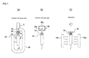
- a preform 1 shown in Fig. 1 (A) is continuously delivered at a predetermined speed.
- the preform 1 is formed as a bottomed tubular member such as test tube by injection-molding the PET.
- the preform 1 is formed with a mouth like the mouth portion 2a of the bottle 2 shown in Fig. 2(G) at the initial time of the molding.
- the mouth portion 2a is also formed with a male thread at the same time of molding the preform 1.
- a sterilizer gas G or mist, or mixture thereof is supplied to the traveling preform 1.
- a hydrogen peroxide is used in the present embodiment as a sterilizer gas (sterilizing agent), another sterilizer or sterilizing agent is also usable.
- the preform 1 is blasted with the hydrogen peroxide gas G through a sterilizer supplying nozzle 6.
- the hydrogen peroxide gas G is divided into two flows within the sterilizer supplying nozzle 6, and one of them is jetted toward inside the preform 1 and the other one is jetted toward an outer surface of the preform 1. After the hydrogen peroxide gas G is blasted through the sterilizer supplying nozzle 6, it flows into the preform in a state of gas, mist, or mixture thereof, or it flows in contact to the outer surface of the preform 1.
- an outside of the flow of the gas G jetted toward inside the preform is covered by an umbrella-shaped member 30.
- the gas G or mist flowing into the preform 1 leaks out of the mouth portion 2a of the preform 1, the flow of the leaking gas G or like collides with the umbrella-shaped member 30, is guided along the inner surface thereof, changes its flow direction towards the outer surface thereof, and contacts the outer surface of the preform 1.
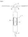
- the hydrogen peroxide gas G blasted to the preform 1 is generated by a sterilizer sterilizer gas generator 7, which will be explained hereinafter with reference to Fig. 4 .
- the hydrogen peroxide gas G flows out of the sterilizer supplying nozzle 6, contacts the inner and outer surfaces of the preform 1.
- the hydrogen peroxide gas G adheres to the surface of the preform 1 as a condensed film of hydrogen peroxide with a concentration of 35 percent by mass with a thickness of preferably 0.001 ⁇ L/cm 2 to 0.5 ⁇ L/cm 2 . More preferably, the amount of the adhering hydrogen peroxide gas G ranges from 0.002 ⁇ L/cm 2 to 0.4 ⁇ L/cm 2 .
- the sterilizer supplying nozzle 6 may be located in a tunnel, and a gripper 32 (see Fig. 6 ) that conveys the preform 1 may be covered with a duct. In this way, the concentration of the hydrogen peroxide gas as the sterilizer in the tunnel can be increased, and the hydrogen peroxide gas can be condensed over the entire surface of the preform 1 introduced at room temperature.
- the hot air P is supplied from an air nozzle 80.
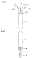
- the hot air P is blasted through a slit-shaped blasting port 80a formed to a box-shaped manifold 80b constituting the air nozzle 80, but the hot air P may be blasted from a tubular blasting nozzle 81 toward the preform 1 as shown in Fig. 7 .
- a suction tube 82 near the blasting nozzle 81 so as to suck foreign substance or material such as dust exhausted outside from the preform 1 by the suction tube 82 at a time of blasting the hot air P from the tubular blasting nozzle 81 into the preform 1.
- the suction tube 82 by recovering the foreign substance by the suction tube 82, the foreign substance can be prevented from mixing into the other preform or bottle formed thereafter.
- the blasting nozzle 81 blasting the hot air P with an opening directed upward and with the preform in the inverted state, in which the hot air P is blasted into the preform 1 through the mouth portion 2a from the lower side of the blasting nozzle 81 of the inverted preform 1.
- the foreign substance existing inside the preform 1 can be removed from the preform 1 by blasting air under pressure through the mouth portion 2a as well as self-gravity thereof.
- the sterilized preform 1 is heated by an infrared heater 18a or other heating means to a temperature suitable for the blow-molding process which will be performed to a temperature of about 90 to 130°C.
- a temperature for heating the mouth portion 2a of the preform 1 is suppressed to a temperature less than 70°C for preventing deformation or like of the preform.
- the preform 1 is, and it is desirable, as shown in Fig. 1 (C) , conveyed while rotating together with the spindle (mandrel) in a suspended upstand state (or upside down state) by inserting a spindle (or mandrel) 43 into the mouth portion 2a.
- the preform 1 can be evenly heated by the infrared heater 18a.
- the hydrogen peroxide adsorbed by the preform 1 is activated and sterilizes bacteria on the preform 1.
- the mold 4 for the blow-molding is continuously the mold traveled at the same speed as the traveling speed of the preform, and is then clamped (mold-clamped). Thereafter, the mold 4 is opened after the blow-molding process is performed to the preform 1 within the mold 4.
- the preform 1 is entirely, except its mouth portion 2a, uniformly heated to a temperature suitable for the heating process shown in Fig. 1(C) , the thus heated preform 1 is placed and set in the mold 4 as shown in Fig. 1(D), and an extension rod (not shown) is inserted into the preform 1 through a center hole of the blow nozzle 5.
- the preform 1 is expanded into the bottle 2 as final product within a cavity C of the mold 4 by sequentially blasting aseptic air, for example, for primary blow-molding and for secondary blow-molding from the blow nozzle 5 into the preform 1.
- the bottle 2 taken out of the mold 4 is filled up with the drink "a" through the filling nozzle 10 as shown in Fig. 2(F) , and subsequently, as shown in Fig. 2(G) , the cap 3 as a lid is applied to the bottle 2.
- the drink “a” may fill the bottle 2 at a normal temperature under an aseptic environment after the sterilizing treatment subjected to the drink itself.
- the drink “a” may fill the bottle 2 at a medium temperature such as 60 to 75 °C.
- a predetermined desirable sterilizing effect against mold spore can be obtained by treating the temperature of the pasteurizer for 5 to 10 minutes at a temperature of more than 60 to 65°C.
- [O] represents a case of sterilizing effect of more than 6.0Log
- [ ⁇ ] represents a case of sterilizing effect of 5.5Log to 6.0Log
- [x] represents a case of sterilizing effect of less than 5.0Log.
- the above test was conducted for the purpose of obtaining a condition for a filling temperature of drink which can achieve the sterilizing effect of more than 6.0Log with respect to fungus (mold) of A. niger NBRC6341 as to a bottle inner surface and a cap inner surface. Further, although another fungus having a heat resisting property more than that of this fungus exists, in view of the sterilizing effect to the preform by chemical agent sterilization and the sterilizing effect to the chamber by SOP treatment, it is considered that commercially suitable aseptic filling operation may be performed by ensuring the sterilizing effect of 6 Log.
- the test was conducted in a condition such that a hot water filled a fungus adhering bottle, an inverted sterilization was performed for 30 seconds after the filling, and subsequently, the filled water was filtrated by a filter and then cultivated. Thereafter, liquid culture medium was mixed and diluted, and was then separately cultivated.
- the case of the middle temperature filling treatment is suitable for acidic drink, carbonated drink, mineral water, which have the nature of suppressing germination of spore fungus, or neutral drink which is proven to a hot bag.
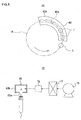
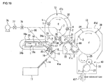
- the aseptic filling system for performing the sterilizing treatment to the preform as mentioned above is constructed as one shown in Fig. 3 , for example.
- the aseptic filling system includes a preform supply machine 11 for sequentially supplying preforms 1, each having a bottomed tubular shape, a blow-molding machine 12, and a filling machine 13 for filling a molded bottle 2 with the drink "a” and sealing the same with a cap 3 (see Fig. 2(G) ).
- the aseptic filling system is surrounded by chambers 41 a, 41b, 41c and 41d at several portions on the way between the blow-molding machine 12 and the filling machine 13.
- the chamber 41b may be mere a frame structure such as shroud with no sealing structure.
- the interior of the chamber 41b may be sterilized by the hydrogen peroxide gas of less than 10mg/L, or portions to which the preform 1 and the bottle 2 contact may be irradiated with a UV lamp (for ultraviolet ray sterilization). Furthermore, portions, to which a mold, an extension rod, a gripper and the like contact, may be wiped up with a chemical agent containing 1 % by mass of ethanol or hydrogen peroxide.
- a preform conveying means, a mold conveying means and a bottle conveying means are located on the way between the preform supplying machine 11 and the filling machine 13, in which the mold conveying means is for conveying the preforms 1 on the first conveying path, the mold conveying means is for conveying the mold 4 having a cavity "C" having a shape corresponding a final product of the bottle 2 (see Fig. 2(D) ) on the second conveying path connected to the first conveying path, and the bottle conveying means is for conveying the bottle 2 molded by the mold 4 on the third conveying path connected to the second conveying path.
- the first conveying path for the preform conveying means, the second conveying path for the mold conveying means and the third conveying path for the bottle conveying means are communicated with each other, and the grippers and like members, not shown, for holding and conveying the preforms 1 and the bottles 2 are provided on these conveying paths.
- the preform conveying means is provided, on its first conveying path, with a preform conveyer 14 for subsequently conveying the preforms 1 at a predetermined interval.
- the preform conveying means is further provided with a line (train) of wheels 15, 16, 17 which receive the preforms 1 from the terminal end of the conveyer 14, and an endless chain 18 which receives the preforms 1 and then conveys the preforms 1.
- A. sterilizer sterilizer gas generator 7 generating the hydrogen peroxide gas G and a sterilizer supplying nozzle 6 for discharging the hydrogen peroxide gas G toward the preform 1 are located on predetermined positions on the traveling path of the preform 1 in the wheel 15.
- the sterilizer sterilizer gas generator 7 is provided with a hydrogen peroxide supplying portion 8 constructed as a twin-fluid spray nozzle for supplying the solution of the hydrogen peroxide as the sterilizer in form of liquid drops and an evaporating portion (evaporator) 9 for evaporating the hydrogen peroxide by heating the mist of the hydrogen peroxide supplied from the hydrogen peroxide supplying portion 8 to a temperature more than its boiling point and less than its non-degradable temperature.
- a hydrogen peroxide supplying portion 8 constructed as a twin-fluid spray nozzle for supplying the solution of the hydrogen peroxide as the sterilizer in form of liquid drops
- an evaporating portion (evaporator) 9 for evaporating the hydrogen peroxide by heating the mist of the hydrogen peroxide supplied from the hydrogen peroxide supplying portion 8 to a temperature more than its boiling point and less than its non-degradable temperature.
- the hydrogen peroxide supplying portion 8 has a structure in which the hydrogen peroxide solution from a hydrogen peroxide supply path 8a and compressed air from a compressed air supply path 8b respectively introduced into the hydrogen peroxide supplying portion 8 are then atomized into the evaporating portion 9.
- the evaporating portion 9 is in form of a pipe with a heater 9a interposed between inner and outer wall portions thereof, and the hydrogen peroxide mist sprayed into this pipe is heated and then evaporated. The evaporated hydrogen peroxide gas is jetted outward of the evaporating portion 9 through the hydrogen peroxide supply nozzle 6.
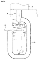
- the sterilizer supply nozzle 6 is branched into a plurality of pipe lines 6a, 6b for sending the hydrogen peroxide gas G.
- the pipe line 6a among the plural pipe lines 6a, 6b has a discharge port facing an opening of the mouth portion 2a of the preform 1.
- the hydrogen peroxide gas G generated by the sterilizer sterilizer gas generator 7 is blasted toward the preform 1 from the discharge port of the pipe line 6a of the sterilizer supply nozzle 6 in form of gas G or mist, or mixture thereof, and flows into the preform 1. In this manner, the hydrogen peroxide adheres to the inner surface of the preform 1.
- dew condensation of the hydrogen peroxide solution in these pipe lines may be prevented.
- dew condensation may also be prevented by winding electric ribbon heater around the pipe lines 6a, 6b and the others.
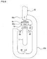
- an umbrella-shaped member 30 which has a lower surface in which an annular groove 30a having approximately semi-circular section is formed.
- the hydrogen peroxide gas G or mist, or their mixture flowing into the preform 1 through the discharge port of the pipe line 6a fills the preform 1, and thereafter, leaks outward.
- the leaked hydrogen peroxide gas G or mist, or their mixture is guided to the outer surface of the preform 1 by the lower surface of the umbrella-shaped member 30 and the annular groove 30a and then flows outward along the outer surface of the preform 1. Accordingly, the hydrogen peroxide leaking from the pipe line 6a also adheres to the outer surface of the preform 1.
- the other pipe line 6b is formed so as to extend in an approximately U-shape along the outer surface of the preform 1, and a discharge port 31 of this pipe line 6b faces the outer surface of the preform 1.
- the hydrogen peroxide gas G generated by the sterilizer sterilizer gas generator 7 is jetted toward the outer surface of the preform also from the discharge port 31 of the other pipe line 6b, and the thus formed hydrogen peroxide gas G or mist, or their mixture is blasted to the outer surface of the preform 1.
- the blasted hydrogen peroxide from the pipe line 6a is mixed with the hydrogen peroxide leaking from the mouth portion 2a of the preform 1 and adheres to the outer surface of the preform, thereby sterilizing bacteria and the like fungus adhering to the outer surface of the preform 1.
- the amount of the hydrogen peroxide solution to be blasted to the inner and outer surfaces of the preform 1 can be adjusted by respectively adjusting the inner diameter of the discharge port 31 of the pipe line 6a for supplying the gas G to the inner surface of the preform 1, the inner diameter of the discharge port 31 of the pipe line 6b, the number of the discharge ports and the like.
- reference numeral 32 denotes a gripper disposed around the wheel 15 that conveys the preform 1.
- An air nozzle 80 ( Fig. 1 (B) ) is disposed on the traveling path of the preform 1 in the wheel 16, the air nozzle 80 acting to activate the hydrogen peroxide adhering to the inner and outer surfaces of the preform 1 by discharging the hot air P toward the preform 1 to thereby discharge the activated hydrogen peroxide externally of the preform 1.
- the air nozzle 80 has a box-shaped manifold 80b bent along a circular arc of the wheel 16, and the blasting port 80a in form of slit is formed in the bottom surface of the manifold 80b.
- the air nozzle 80 is located above the wheel 16 so that the blasting port 80a of the air nozzle 80 extends along the traveling path of the preform 1 in the wheel 18.
- a blower 76, an HEPA filter 77, and an electric heater 78 are connected in series to the manifold 80b. Outside air taken by the blower 76 is sterilized by the HEPA filter 77 and then heated by the electric heater 78 to generate the hot air P which is then send into the air nozzle 80.
- Air to be supplied to the air nozzle 80 may be a compressed air which has a high propelling force and is sterilized by an aseptic filter without using the air from the blower 76. Moreover, a highly pressurized air using for blow-molding in the blow molding machine 12 may be re-used by being recovered.
- the hot air P supplied into the manifold 80b of the air nozzle 80 is jetted from the blasting port 80a, flows toward the preform 1 traveling under the blasting port 80a with the mouth portion 2a thereof being directed upward, and a part of the hot air P flows into a hollow interior of the preform 1 and the other part thereof flows along the outer surface of the preform 1.
- the foreign substance removing percentage or ratio can be increased by arranging a suction tube 82 as shown in Fig. 7 and inverting the nozzle 81 and the preform 1 as shown in Fig. 8 .
- the supply of the hot air P may be performed by using an air nozzle 83 shown in Fig. 9 .
- the air nozzle 83 has a structure similar to that of the sterilizer supply nozzle shown in Fig. 6 .
- reference numerals 83a and 83b denote a plurality of blanched pipe lines for sending the hot air P, in which a discharge port of one pipe line 83a faces the opening of the mouth portion 2a of the preform.
- the hot air P is jetted from the discharge port of the pipe line 83a toward the preform 1 and flows into the preform 1.
- the hydrogen peroxide adhering to the inner surface of the preform 1 is activated and the surplus hydrogen peroxide is removed.
- Reference numeral 84 denotes an umbrella-shaped member covering the periphery of the discharge port of the pipe line 83a, and an annular groove 84a having approximately semi-circular sectional shape is formed in the lower surface of the umbrella-shaped member 84.
- the hot air P introduced into the preform 1 from the discharge port of the pipe line 83a fills the interior of the preform 1, and then, leaks from the mouth portion 2a of the preform 1.
- the leaking hot air P is guided to the outer surface of the preform 1 by the lower surface of the umbrella-shaped member 84 and the annular groove 84a and flows along the outer surface of the preform 1 so that the hot air P leaking from the pipe line 83a also contacts the outer surface of the preform 1.
- the other pipe line 83b is formed so as to extend in an approximately U-shape along the outer surface of the preform 1, and a discharge port 85 of this pipe line 83b faces the outer surface of the preform 1.
- the hot air P is jetted toward the outer surface of the preform 1 also from the discharge port 85 of the other pipe line 83b and contacts the outer surface of the preform 1.
- the hot air P from the pipe line 83a is mixed with the hot air P leaking from the mouth portion 2a of the preform 1 and adheres to the outer surface of the preform 1. Then, the surplus hydrogen peroxide adhering to the outer surface of the preform 1 is removed.
- the wheels 15 and 16 are surrounded by the chamber 14a, to which exhaust means composed of a filter 36 for filtrating the air inside the chamber 41a and a blower 37 is connected. According to such connection, the surplus hydrogen peroxide discharged from the sterilizer supply nozzle 6 is removed by the filter 36 of the exhaust means, and thereafter, is discharged outside the chamber 41a. Thus, the flow-in of the hydrogen peroxide into the adjacent blow-molding machine 12 can be prevented. It is preferred to adjust the supply amount into or exhaust amount from the chamber 41a so as to create a negative pressure in the chamber 41a lower than atmospheric pressure.
- bacteria or like fungus may be prevented from invading into the chamber 41a now under negative pressure by locating the chamber 41a, the heating furnace 33, the chamber 41b and so on within a clean room, not shown, such as chamber 41 b.
- the endless chain 18 is disposed as the conveying path of the preforms 1 within the heating furnace 33 provided with the infrared heater 18a described above.
- a number of spindles 43 shown in Fig. 1(C) ate attached to the endless chain 18 at a constant pitch. Each spindle 43 can rotate while traveling together with the traveling of the endless chain 18.
- the spindle 43 is inserted as shown in Fig. 1(C) , so that the preform 1 can be kept in its positively standing attitude. It may be further possible to convey the preform in the standing attitude as shown in Fig. 8 by replacing the spindle with a mandrel.
- the heating furnace 33 is provided with a furnace chamber extending in one direction. Inside the furnace chamber, the endless chamber 18 is stretched between a pair of pulleys 34a and 34b opposing to each other in a horizontal plane.
- the endless chain 18 and associated members constitute an endless conveyer for conveying a number of the preforms 1 in a suspended attitude.
- the infrared heaters 18a are attached to the inner peripheral wall of the furnace chamber along the outward path and return path of the traveling of the endless chain 18.
- the preform 1 When the preform 1 is received by the spindle 43 through the preform conveyer 14 and the row of the wheels 15, 16 and 17, the preform 1 rotates and travels along the inner wall surface of the heating furnace 33.
- the infrared heaters 18a are attached throughout the inner wall surface of the heating furnace 33, so that the preform 1 conveyed by the spindle 43 is heated by these infrared heaters 18a.
- the preform 1 rotates in the heating furnace 33 together with the rotation of the spindle while being evenly heated by the infrared heaters 18a, and portions other than the mouth portion 2a of the preform 1 are heated up to a temperature 90°C to 130°C suitable for the blow-molding.
- the heating temperature to the mouth portion 2a is regulated to less than 70°C so as not to damage the sealing performance and not to deform the preform 1 when the cap is applied to the mouth portion 2a.
- the blow-molding machine 12 is provided with several sets of the mold 4 and the blow nozzle 5 ( Fig. 2(D) ) for receiving the preform heated by the infrared heater 18a of the preform supplying machine 11 and then molding the preform 1 into the bottle 2.
- the second conveying path of the mold conveying means is located within the blow-molding machine 12.
- the second conveying path is composed of a line of wheels 19, 20, 21 and 22.
- a plurality of molds 4 and blow nozzle 5 are located around the wheel 20, and turn around the wheel 20 at a constant speed together with the wheel 20.
- the gripper, not shown, of the wheel 19 receives the preform 1 heated in the heating furnace 33 of the preform supplying machine 11 and then transfers the preform 1 to the mold 4 located around the wheel 20, the mold 4 now being opened in two mold halves is closed to thereby grip the preform 1 such as shown in Fig. 2(D) .
- the preform 1 in the mold 4 is blown with highly pressurized air through an aseptic filter for blow-molding from a blow nozzle 5 while being rotated around the wheel 20 together with the mold 4 and the blow nozzle 5, thereby being molded into a final product of a bottle 2.
- Fig. 1(C) since the preform 1 is heated evenly to a predetermined temperature within the heating furnace 33, the blow-molding process can be smoothly performed.
- the hydrogen peroxide adhering to each preform 1 is removed from the preform 1 before the entrance into the heating furnace 33 by blowing the hot air P. Accordingly, the seal member and other components or members located inside the blow-molding machine 12 becomes free from any damage by the adhesion of the hydrogen peroxide. Moreover, whitening (bleaching), distortion, uneven molding, or like defect to the bottle 2 resulted from the adhesion of the hydrogen peroxide can be prevented from causing.
- the mold When the preform 1 closely contacts the inner surface of the cavity C of the mold 4 to thereby form the bottle 2, the mold is opened at an instance contacting the wheel 21, and the bottle 2 is received by the gripper, not shown, of the wheel 21.
- the bottle 2 reaching the wheel 21 from the blow-molding machine 12 is inspected whether it is defective or not in the molded performance by an inspection device 35 arranged on the outer periphery of the wheel 21.
- the inspection device 35 may be provided with a light source and a camera for inspecting the top surface of the mouth portion 2a of the molded bottle 2 is made to be flat or not.
- the inspected bottle 2 which is judged to be defective, is rejected from the conveying path by a rejection device, not shown, and only an acceptable product is conveyed to the wheel 22.
- the filling machine 13 is provided therein with the third conveying path as bottle conveying means, and such third conveying path is equipped with a line (train) of wheels 23, 24, 25, 26 and 27.
- a number of filling nozzles 10 for filling the aseptic bottles 2 with the drink "a” are located so as to constitute a filler 39, and around the wheel 26, a capper 40 for applying the cap 3 ( Fig. 2(G) ) is also constituted to thereby seal each of the bottles 2 filled up with the drink "a".
- filler 39 and capper 40 Since conventionally known filler and capper may be usable as such filler 39 and capper 40, detailed descriptions thereof will be omitted herein.
- the chamber 41c is located so as to surround the wheel 22, and this chamber 41c functions as surrounding air shut-off chamber for shut off surrounding (atmosphere) air existing between the chamber 41b and the chamber 41d.
- Exhaust means like that composed of the filter 36 and the blower 37 and connected to the chamber 41a shown in Fig. 3 is connected to this chamber 41c to thereby exhaust outward the inner air in the chamber 41d.
- gas or mist of the sterilizer and the cleaner generated within the chamber 41d is rejected outside the chamber 41c by performing the COP (Cleaning Out of Place) with respect to the interior of the chamber 41d of the filling machine 13, and to thereby prevent the mist or line from flowing into the chamber 41 b of the blow-molding machine 12.
- the preforms 1 are conveyed toward the heating furnace 33 by the preform conveyer 14 and the line of the wheels 15, 16, 17.
- the hydrogen peroxide gas G or mist, or their mixture is supplied toward the preforms 1 from the sterilizer supplying nozzles 6, respectively.
- Part of the hydrogen peroxide supplied from the sterilizer supplying nozzle 6 is adsorbed by the preform 1, and the remaining excess of the hydrogen peroxide remains on the surface of the preform 1.
- the hot air P is blasted from the air nozzle 80 to the preform 1 at the time when the preform adhered with the hydrogen peroxide travels around the wheel 16.
- the blasting of the hot air P the remaining excess of the hydrogen peroxide is quickly removed from the surface of the preform 1.
- the hot air P may be blasted into the preform 1 through the air nozzle 81 to blow away foreign matters from inside the preform 1, and the foreign matters blown away may be collected through the suction tube 82.
- the air nozzle 81 and the preform 1 may be inverted from the position shown in Fig. 7 so that foreign matters in the preform 1 can be easily removed to outside the preform 1.
- the preform 1 is received by the spindle 43 above the endless chain 18 and then conveyed into the heating furnace 33.
- the preform 1 in the heating furnace 33 is heated by the infrared heater 18a to thereby evenly heat the entire of the preform, except the mouth portion 2a, to a temperature suitable for the blow molding treatment.
- the hydrogen peroxide adsorbed by the preform 1 is activated and sterilizes bacteria on the preform 1.
- the preform 1 heated in the heating furnace 33 and sterilized at the same time travels around the outer periphery of the wheel 20, the preform 1 is held by the mold 4 as shown in Fig. 2(D) , and aseptic highly-pressurized air is blasted through the blow nozzle 5, and then, the preform 1 is expanded as a product bottle 2 within the cavity C of the mold 4.
- the thus molded bottle 2 is taken out of the mold 4 after opening the mold 4 by the gripper of the wheel 21, and the bottle 2 is then inspected by the inspection device as to whether it is defective product or not.
- the defective bottle 2 is rejected outward from the traveling line of the bottles by a rejecting device, not shown, and only a non-defective bottle 2 is guided and travels into the filling machine while being transferred to the line of the wheels 22, 23, 24, 25, 26 and 27.
- the sterilized drink “a” fills the bottle 2 by the filling nozzle 10 of the filler 39 as shown in Fig. 2(F) .
- the bottle 2 filled up with the drink “a” is applied with the cap 3 by the capper 40 to be sealed (see Fig. 2(G) ), and discharged through the outlet port of the chamber 41d.
- the interior of the chamber 41d of the aseptic filling machine 13 is sterilized (SOP) by scattering the hydrogen peroxide gas or peracetic acid solution before production of package. Then, after the sterilization, by supplying the air through the aseptic filter, the interior of the chamber 41d can be kept at positive pressure.
- SOP sterilized
- the surrounding air shut-off chamber 41c is positioned between both the cambers 41b and 41d and such air and the like are discharged outward therefrom, high-humid air in the filling area of the chamber 41d can be properly prevented from entering into the molding area in the chamber 41 b.
- the sterilizer supply nozzle 6 and the air nozzle 80 for sterilizing the preform 1 for the sterilization of the bottle 2 to the portions of the wheels 22 and 23.
- the sterilizer since the sterilizer is exhausted outward from the surrounding air shut-off chamber 41c by the exhausting means in the surrounding air shut-off chamber 41c, the sterilizer can be shut off from flowing toward the side of the blow-molding machine 12.
- steps shown in Figs. 10(A) and 10(B) are used instead of the steps shown in Figs. 1(A) and 1 (B) .
- a drop Q of a solution of hydrogen peroxide as the sterilizer is dripped into the preform 1 through the mouth portion 2A.
- the amount of drops Q falls within the maximum amount of hydrogen peroxide that can be adsorbed by one preform 1.
- a large number of preforms 1 containing drops of hydrogen peroxide are put in a container 86 and sealed. More specifically, a sealed bag 87 is put in the rigid container 86, a large number of preforms 1 are put in the sealed bag 87, the sealed bag 87 is sealed, and then the container 86 is covered with a lid 86a. Aging occurs in the container for a predetermined time, and the hydrogen peroxide supplied into the preforms is adsorbed by the preforms 1.
- the place where the aging is not limited to the interior of the sealed bag 87, and the aging can occur in any sealed chamber.
- the sealed bag 87 is opened, and the preforms 1 are removed from the sealed bag 87 and heated to a blow-molding temperature as shown in Fig. 1(C) . After that, the preforms 1 are molded into packaged products through the steps shown in Figs. 1(D) to 2(G) .
- an aseptic package provided with a bottle 2 and a cap 3 such as shown in Fig. 14(K) can be manufactured as in the case of the first embodiment.
- the bottle 2 is formed as an aseptic package through sterilizing process, molding process, drink filing process and sealing process as shown in Fig. 11 (A) to Fig 14(K) .
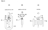
- the preforms 1 shown in Fig. 11 (A) are continuously conveyed at a predetermined speed, and sterilizer gas G or mist, or their mixture is supplied to the preforms 1 now traveling.
- the preform 1 has a structure similar to that of the preform 1 according to the first embodiment.
- the sterilizer is also supplied in the same manner as in the first embodiment, and the gas G or mist of hydrogen peroxide or a mixture thereof as the sterilizer contacts and adheres to the inner and outer surfaces of the preform 1.
- Part of the hydrogen peroxide on the surface of the preform 1 is adsorbed by the preform 1, and the remaining excess of the hydrogen peroxide remains on the surface of the preform 1.
- preliminarily heat the preform by, for example, blasting heated air to the preform 1 just before the blasting of the gas G to the preform 1 as shown in Fig. 11 (A) .
- the preform 1 suppled with the hydrogen peroxide is also supplied with the hot air P by the air nozzle 80 as shown in Fig. 11 (B) .
- the hot air P can be supplied in the same manner as in the first embodiment.
- the sterilized preform 1 is heated by the infrared heater 18a and other heating means to a temperature suitable for the blow-molding treatment which will be performed thereafter. Such temperature is about 90 °C to 130°C.
- the mouth portion 2a of the preform 1 is made to prevent the heat of the infrared heater 18a from being transferred to the mouth portion 2a not to be deformed by the heat.
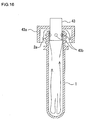
- An umbrella-shaped member 43a is attached to an outer portion of the spindle 43 as occasion demands as shown in Fig. 16 . And a plurality of elastic members 43b, each having a ball-like shape, are embedded.
- the preform 1 When the lower portion of the spindle 43 is inserted into the mouth portion 2a of the preform 1, the preform 1 is supported to the spindle 43 by the elastic deformation of the elastic members 43b. In the case when the umbrella-shaped member 43a is provided, the mouth portion 2a of the preform 1 is covered by this umbrella-shaped member 43a.
- a gap is formed to a portion between the inner surface of the mouth portion 2a of the preform 1 and the lower portion of the spindle 43, and a portion between the outer surface of the mouth portion 2a of the preform 1 and the umbrella-shaped member 43a. Because of the formation of such gap, the air inside the preform 1 heated by the heat from the infrared heater 18a changes to the hot air, which then flows outward of the preform 1 from the interior thereof through such gap while heating the mouth portion 2a of the preform 1.
- the hot air passing through the gap heats the mouth portion 2a, but attention should be paid so that the heating temperature is less than about 70 °C, to prevent the deformation of the mouth portion 2a. According to such heating to the mouth portion 2a, very small amount of hydrogen peroxide remaining in the preform 1 is activated and the mouth portion 2a is hence properly sterilized.
- the preform 1 When the preform 1 is heated as mentioned above, the preform 1 is conveyed in a state suspended at a positively standing attitude by the insertion of the spindle 43 into the mouth portion 2a thereof, preferably, while rotating together with the spindle 43 around the axis thereof. According to such operation, the preform 1 can be entirely, except the mouth portion 2a, heated evenly by the infrared heater 18a at a temperature about 90 °C to 130°C.
- the preform 1 may be conveyed in an inverted attitude.
- the hydrogen peroxide adsorbed by the preform 1 is activated and sterilizes bacteria on the preform 1.
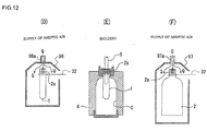
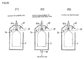
- the heated preform 1 is released from the spindle 43 as shown in Fig. 12(D) , and conveyed to the mold 4 for being subjected to the blow-molding treatment while blasting an aseptic air Q from the mouth portion 2a as shown in Fig. 12(E) .
- the preform 1 can be moved into the mold 4 while keeping the aseptic condition.
- Hot air may be used as such aseptic air Q.
- the preform 1 can be prevented from lowering in its temperature by the blasting of the hot air.
- a cover 96 is disposed in form of a tunnel so as to surround the traveling path of the preform 1 at a portion at which the heated preform 1 is conveyed toward the mold 4.
- a top portion of the tunnel-shaped cover 96 covering the mouth portion 2a of the preform 1 from the upper side thereof is formed as a roof having an inclining surface.
- nozzles 96a through which the aseptic air Q is blasted toward the mouth portion 2a of the preform 1 are provided in form of line or slit. According to such structure, the aseptic air Q can be effectively supplied to the preform 1, and the preform 1 travels within the chamber 41b with the aseptic condition being maintained.
- the preform 1 with the aseptic condition having been maintained by the blasting of the aseptic air Q is placed in the mold 4 as shown in Fig. 12(E) .
- the mold 4 is clamped (mold-clamped) while traveling at the same traveling speed as that of the preform 1, is subjected to the blow-molding treatment, and the mold 4 is thereafter opened.
- the preform 1 is heated entirely, except the mouth portion 2a thereof, in the heating process shown in Fig. 11 (C) to a temperature suitable for the molding the preform 1. Accordingly, as shown in Fig. 12(E) , when the extension rod 5 is inserted into the preform 1 after being placed in the mold 4, the preform 1 is extended within the mold 4 in the longitudinal direction thereof.
- the mold 4 is opened while being traveled, and the product bottle 2 is then taken out of the mold 4.
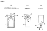
- the bottle 2 after taken out of the mold 4 is conveyed till the hydrogen peroxide supply process shown in Fig. 13(G) starts while blasting the aseptic air Q from the mouth portion 2a side via nozzle 97a, as shown in Fig. 12(F) .
- the bottle 2 is conveyed directly below a hydrogen peroxide supply nozzle 93 so as not to be contaminated as possible as can by bacteria and the like fungus.
- the aseptic air Q shown in Fig. 12(F) is preferably hot air.
- the hot air since the temperature of the bottle 2 is prevented from lowering, the sterilizing effect by the hydrogen peroxide in the subsequent process can be expected to be improved.
- a cover 97 is disposed in form of a tunnel so as to surround the traveling path of the bottle 2 at a portion at which the bottle 2 is conveyed toward the hydrogen peroxide supply nozzle 93 (see Fig. 13 (G) ).
- a top portion of the tunnel-shaped cover 97 covering the mouth portion 2a of the bottle 2 1 from the upper side thereof is formed as a roof having an inclining surface.
- nozzles 97a through which the aseptic air Q is blasted toward the mouth portion 2a of the bottle 2 or traveling path are provided in form of line or slit. According to such structure, the aseptic air Q can be effectively supplied to the preform 2, and the bottle 2 travels into the chambers 41b and 41c with the aseptic condition being maintained.
- the bottle 2 blasted with the aseptic air Q is then sterilized by applying the hydrogen peroxide as sterilizer as shown in Fig. 13(G) .
- the hydrogen peroxide mist M or gas G, or mixture thereof is blasted to the bottle 2 now being conveyed from the nozzle 93 for sterilization 93.
- the sterilizing nozzle 93 is arranged so as to face the mouth portion 2a of the bottle 2.
- the hydrogen peroxide mist M or gas G, or mixture thereof drops downward from the tip end of the sterilizing nozzle 93 into the bottle 2 through the mouth portion 2a thereof while contacting the inner surface of the bottle 2.
- a tunnel 4 is provided to a portion on the traveling path of the bottle 2, and the hydrogen peroxide mist M or gas G, or mixture thereof discharged from the sterilizing nozzle 93 flows downward along the outer surface of the bottle 2 and stays inside the tunnel 44, so that the hydrogen peroxide mist M or gas G, or mixture thereof effectively adheres to the outer surface of the bottle 2.
- the hydrogen peroxide mist M or gas G may be generated by the mist generator 7 shown, for example, in Fig. 4 .
- the sterilizing nozzle 93 may be located to a predetermined position on the way of the conveying path or moved synchronously with the bottle 2.
- the mist M or gas G, or mixture thereof contacts the inner and outer surfaces of the bottle 2, and at such instance, since the heat applied to the bottle 2 in the state of the preform 1 and in the state shown in Fig. 12(F) remains, the bottle 2 is maintained with the predetermined temperature, thus being effectively sterilized.
- This predetermined temperature is preferably 40°C to 80°C in the case of the preform 1 being formed of PET, and more preferably, 50 °C to 75 °C. In the case of less than 40 °C, the sterilizing performance is extremely degraded, and on the other hand, in the case of more than 80°C, the bottle 2 may be contracted after the molding, thus being inconvenient.
- the bottle 2 After the blasting of the mist M or gas G, or mixture thereof, the bottle 2 is subjected to an air rinse treatment as shown in Fig. 13 (H 1). Such air rinsing is performed by blasting an aseptic air N from a nozzle 45 into the bottle 2, and the flow of such aseptic air N removes foreign substance, hydrogen peroxide or the like from the interior of the bottle 2. At that time, the bottle 2 keeps its positively standing attitude.
- an umbrella-shaped member 84 may be attached to the nozzle 45 as like as that shown in Fig. 9 .
- the aseptic air N overflowing from the bottle 2 then flows toward the outer surface of the bottle 2 by the guidance of the inclination of the umbrella-shaped member 84, thereby rinsing the outer surface of the bottle 2.
- an air rinsing process shown in Fig. 13 (H2) may be adopted in place of the air rinsing process shown in Fig. 13 (H 1).
- This air rinsing process shown in Fig. 13(H2) may be performed subsequently after the air rinsing process shown in Fig. 13(H1) by blasting the aseptic air N into the bottle 2.
- the umbrella-shaped member 84 may be attached to a nozzle 45 shown in Fig. 13(H2) .
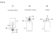
- the hydrogen peroxide adhering to the bottle 2 may be washed away and an aseptic air rinsing may be performed with aseptic water of normal temperature or hot water of 15°C to 85°C for removing the foreign substance and the like, as shown in Fig. 14(I) .
- aseptic water normal temperature or hot water of 15°C to 85°C for removing the foreign substance and the like, as shown in Fig. 14(I) .
- the rinsing step using hot water shown in Fig. 14(I) in which the hydrogen peroxide on the bottle 2 is washed away with hot water or the like after air rinsing, is not required. As occasion demands, however, the rinsing with aseptic water can be performed.
- the drink “a” fills the bottle 2 from the filling nozzle 10, as shown in Fig. 14(J) , and as also shown in Fig. 14(K) , the cap 3 as a lid is applied to the bottle 2 to be sealed, and the bottle 2 is produced as aseptic package.
- the bottle sterilization process mentioned above may be also possible to eliminate the bottle sterilization process mentioned above and to fill the bottle 2 with the drink "a” under a medium temperature of about 70°C.
- the filling is performed at the medium temperature, existence of spore fungus within the drink “a” and the bottle 2 may be permitted, but mold, yeast or the like is sterilized by the heat possessed by the drink "a” itself, and the PET bottle 2 is not deformed.
- the filling process is performed under the medium temperature, it is suitable for the drink "a” to be acidic drink or mineral water having a property for suppressing germination of the spore fungus.
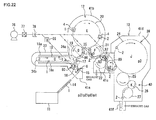
- An aseptic filling apparatus for carrying out the method of sterilizing the bottle 2 as mentioned above has a structure or configuration shown in Fig. 14 , for example.
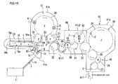
- the aseptic filling system is equipped with: the preform supplying machine 11 for supplying the preforms 1, each having a bottomed tubular shape and having the mouth portion 2a (see Fig. 11 (A) ), subsequently at a predetermined interval; the blow-molding machine 12; the sterilizing machine 88 for sterilizing the molded bottles 2; and the filling machine 13 for filling the bottles 2 (see Fig. 12(F) )with the drink "a” and sealing the bottles 2 with the caps 3, respectively, (see Fig. 14(K) ).
- the portion between the blow-molding machine 12 to the filling machine 13 is covered by the chambers 41a, 41b, 41c1, 41c2, 41c3, 41d, 41e, and 41f.
- the chamber 41a is located to the position corresponding to the portion at which the sterilizer is applied to the preform
- the chamber 41b is located to the position corresponding to the portion at which the bottle 2 is molded
- the chamber 41c1 is located to the position corresponding to the portion at which the bottle 2 is conveyed into the sterilizing machine 88
- the chamber 41c2 is located to the position corresponding to the portion at which the sterilizer is applied to the bottle 2 and the bottle 2 is rinsed
- the chamber 41d is located to the position corresponding to the portion at which the bottle 2 is filed up with the drink "a" as a content and then sealed.
- the portion between the chamber 41b to the chamber 41c1 is maintained as a clean room.
- the portions to which the preform 1 and the bottle 2 contact may be irradiated with an UV lamp (for ultraviolet ray sterilization), or portions to which the mold 4, the extension rod 5, the gripper 32 and the like contact may be wiped up with chemical agent including ethanol or hydrogen peroxide of the amount of 1% by mass.
- a preform conveying means for conveying the preforms 1 on the first conveying path
- a mold conveying means for conveying the molds 4 having cavities C, each in form of the product bottle 2, on the second conveying path connected to the first conveying path
- a bottle conveying means for conveying the bottles 2 molded by the molds 4 on the third conveying path connected to the second conveying path, while sterilizing and filling the bottles 2.
- the first conveying path of the preform conveying means, the second conveying path of the mold conveying means and the third conveying path of the bottle conveying means are communicated with each other, and on the ways of these conveying paths, the grippers, not shown, for conveying the preforms 1 and the bottles 2 are located in the state of the bottle being held.
- the preform conveying means is provided with a preform conveyer 14 on the way of the first conveying path for conveying the preforms 1 subsequently at a predetermined interval.
- the preform conveying means is further provided with a line of the wheels 15, 16 and 17 for receiving the preform 1 from the terminal end of the preform conveyer 14 and then conveying them, and the endless chain 18 for traveling the preforms 1 after the reception thereof.
- the sterilizer gas generator 7 such as shown in Fig. 4 for generating the hydrogen peroxide gas G and the sterilizer supplying nozzle 6 such as shown in Fig. 11 (A) for blasting the hydrogen peroxide gas G toward the preform 1.
- the air nozzle 80 (see Fig. 11 (B) ) fir activating the hydrogen peroxide adhering to the inner and outer surfaces of the preform 1 and discharging it out of the preform 1 by blasting the hot air P toward the preform 1.
- the wheels 15 and 16 are surrounded by the chamber 41a, which is coupled with the exhaust means composed of the filter 36 decomposing the sterilizer such as hydrogen peroxide in the air inside the chamber 41a and the blower 37 as like as the first embodiment as shown in Fig. 3 .
- the exhaust means composed of the filter 36 decomposing the sterilizer such as hydrogen peroxide in the air inside the chamber 41a and the blower 37 as like as the first embodiment as shown in Fig. 3 .
- a heating furnace 33 for heating the preform 1 to a temperature suitable for molding the preform 1 is disposed to a portion, on the way of the first conveying path, from the wheel 17 contacting the wheel 16 to the wheel 19 contacting the second conveying path.
- This heating furnace 33 is also composed of as like as that in the first embodiment.
- the preform 1 is evenly heated during the traveling within the heating furnace 33, and the preform 1 is heated entirely, except the mouth portion 2a thereof, to a temperature of 90°C to 130°C suitable for the blow-molding treatment.
- the mouth portion 2a is heated less than 70°C so as not to damage the sealing performance when the cap 3 is applied.
- the blow-molding machine 12 is arranged around the second conveying path.
- the blow-molding machine 12 has a structure as like as that of the first embodiment, which receives the preform 1 heated in the heating furnace 33 and molds the preform into the bottle 2.
- a cover 96 covering the mouth portion 2a of the preform 1 traveling around this wheel 19 is provided in a tunnel ( Fig. 12(D) ) so as to cover the mouth portion 2a from the upper side.
- Aseptic air Q is blasted into this cover 96 toward the mouth portion 2a of the preform 1.
- the aseptic air Q may be part of the aseptic air P supplied from the aseptic air supplying device shown in Fig. 5(B) in the first embodiment.
- the preform 1 is surrounded by the chamber 41b formed as a clean room and also covered by the cover 86 containing the aseptic air Q, and thus, the preform 1 is conveyed toward the blow-molding machine 12 with the high aseptic condition being maintained.
- the mold 4 in the blow-molding machine 12 is opened at a position in contact to the wheel 21 as a starting end of the third conveying path, and the bottle 2 is received by the gripper, not shown, of the wheel 21.
- the bottle 2 conveyed out of the blow-molding machine 12 to the wheel 21 is inspected by the inspection device 35 disposed as occasion demands to the periphery of the wheel 21 to inspect the presence of the defect in the molding process.
- the inspection device the like one as used in the first embodiment may be used.
- the bottle 2 judged as defective is rejected by a rejection device, not shown, from the conveying path, and only the bottle 2 judged to be acceptable is conveyed to the wheel 22.
- a cover 97 covering the mouth portion 2a of the bottle 2 is provided in form of tunnel ( Fig. 12(F) ) so as to cover the mouth portion 2a thereof from the upper side.
- Aseptic air Q blasted into this cover 97 may be a part of the aseptic air P supplied from the aseptic air supplying device shown in Fig. 5(B) in the first embodiment.
- a sterilizer supplying nozzle 93 (see Fig. 13(G) ) and an aseptic air supplying nozzle 45 (see Fig. 13 (H1) or (H2)) are provided in the line of the wheels 90, 91, 92 and 23 continuous to the wheel 89 on the way of the third conveying path.
- a plurality of sterilizer supplying nozzles 93 are located to predetermined positions on the way of the bottle traveling path around the wheel 90, and the tunnels 44(each shown in Fig. 13(G) ) through which the bottle 2 passes is also located in correspondence with the sterilizer supplying nozzle 93.
- the hydrogen peroxide mist M or gas G, or mixture thereof blasted from the sterilizer supplying nozzle 93 enters the bottle 2 and adheres to the inner surface of the bottle 2 to thereby form a thin film, and also flows along the outer surface of the bottle 2, which then fills the interior of the tunnel 44 and adheres to the outer surface of the bottle 2 to thereby form a thin film thereon.
- one or a plurality of aseptic air supplying nozzles 45 are located to predetermined positions on the way of the bottle traveling path around the wheel 92.
- the aseptic air N blasted from the aseptic supplying nozzle 45 contacts the inner and outer surfaces of the bottle 2 and removes the film of the surplus hydrogen peroxide adhering to the surface of the bottle 2.
- the hot air is used as such aseptic air N, the hydrogen peroxide adhering to the inner and outer surfaces of the bottle 2 is activated, thereby enhancing the sterilizing effect.
- the sterilizer supplying nozzles 93 and the aseptic air supplying nozzles 44 are located around the wheel 90 and 92, respectively, at the same pitch as that of the bottles 2, and the hydrogen peroxide gas G and the aseptic air N are blasted into the bottles 2 while being turned synchronously therewith.
- the filler 39 and the capper 40 are located to positions on the way from the wheel 24, to which the wheel 23 is contacted, to the wheel 27 in the third conveying path.
- the filler 39 is constituted by a number of filling nozzles 10 (see Fig. 14(J) ) located around the wheel 24 each for filling the bottle 2 with the drink "a", and the capper 40 is for applying the cap 3 (see Fig. 14(K) ) disposed around the wheel 26 to the bottle 2 filled up with the drink "a".
- the filler 39 and the capper 40 are ones identical to those of the first embodiment.
- the periphery of the wheel 15 is surrounded by the chamber 41 a on the way of the first to third conveying paths.
- the peripheral portion from the wheel 16 to the wheel 21 is surrounded by the chamber 41b.
- the peripheral portion from the wheel 22 and the wheel 89 is surrounded by the chamber 41c1.
- the peripheral portion from the wheel 90 to the wheel 23 is surrounded by the chamber 41c2.
- the peripheral portion from the wheel 24 to the wheel 27 is surrounded by the chamber 41d.
- the chamber 41b is constituted as a clean room, thus preventing bacteria or like fungus from entering into the chamber 41 b.
- the interiors of these chambers 41a, 41b, 41c1, 41 c2, 41d, 41 e and 41f are sterilized by, for example, the COP (cleaning outside of place) treatment and the SOP (sterilizing outside of place) treatment, and thereafter, the sterilizer and the cleaner gas or mist in the chambers 41a, 41 b, 41 c2, 41 d, 41e and 41f are exhausted from the chambers 41a, 41 b, 41 c2, 41 d, 41e and 41f outside thereof by the exhausting means such as shown in Fig. 3 , respectively.
- the chambers 41c1 functions as a atmosphere shut-off chamber for shutting off the atmosphere between the chamber 41b and the chamber 41d, thereby preventing the cleaner gas or like generated by the COP and SOP treatments and the sterilizer mist or like generated in the chamber 41 c2 from flowing into the chamber 41 b of the blow-molding machine 12 via the chamber 41c1.
- the preform 1 is conveyed by the line of the wheels 15, 16 and 17 toward the heating furnace 33.
- the sterilizer gas G or mist M, or the mixture thereof is supplied to the preform 1 through the sterilizer supplying nozzle 6.
- the hot air P is blasted from the air nozzle 80 to the preform 1.
- the hydrogen peroxide adhering to the preform 1 is activated by the heat of the hot air P to thereby sterilize the bacteria and the like fungus.
- the surplus hydrogen peroxide adhering to the surface of the preform 1 is removed by such heat of the hot air P.
- Foreign substance in the preform 1 can be blasted out of the interior of the preform 1 by blasting the hot air P by means of the air nozzle 81 shown in Fig. 7 , and the blasted foreign substance may be recovered by a suction tube 82.
- the air nozzle 81 and the preform 1 in the inverted attitude as shown in Fig, 8 with respect to the attitude shown in Fig. 7 , the foreign substance in the preform 1 may be removed our of the preform 1.
- the preform 1 is received by the spindle 43 on the endless chain 18 (see Fig. 11 (C) ), and then transferred to the heating furnace 33.
- the preform 1 is then heated by the infrared heater 18a within the heating furnace 33, and the preform 1 is entirely heated, except the mouth portion 2a thereof, to the temperature suitable for the blow-molding treatment.
- the preform 1 heated in the heating furnace 33 to the temperature suitable for the blow-molding treatment is blasted with the aseptic air Q while passing under the cover 96 during the traveling around the wheel 19. According to such blasting of the aseptic air Q, the preform 1 is conveyed to the blow-molding machine 12 while the aseptic condition being maintained. In the case where the aseptic air Q is hot air, the preform 1 can arrive at the blow-molding machine 12 with the temperature suitable for the blow-molding treatment being maintained.
- the preform 1 passes around the outer periphery of the wheel 20, the preform 1 is held by the mold 4 as shown in Fig. 12(E) , and is blasted with the highly pressurized aseptic air so that the preform 1 is expanded into the product bottle 2 within the cavity C of the mold 4.
- the product bottle 2 is taken out of the mold 4 by the gripper of the wheel 21 after opening the mold 4, and thereafter, is subjected to the inspection by the inspection device 35 whether the molding defective is present or not.
- the defective bottle 2 is removed from the conveying line by the rejecting device, not shown, and only the acceptable (good) bottle 2 is transferred to the wheel 22 and then conveyed to the sterilizing machine 88.
- the aseptic air Q is blasted to the bottle 2 while passing under the cover 97. Accordingly, the bottle 2 is conveyed to the sterilizing machine 88 with the aseptic condition being maintained.
- the preform 1 can arrive at the sterilizing machine 88 while maintaining the temperature suitable for the sterilization.
- the bottle 2 is sterilized by blasting the hydrogen peroxide mist M or gas G, or the mixture thereof, as shown in Fig. 13(G) ), while traveling around the wheel 90 within the sterilizing machine 88, and subsequently, the bottle 2 is air-rinsed by blasting the aseptic air N as shown in Fig. 13(H1) or (H2) while traveling around the wheel 92.
- the bottle 2 in the filling machine 13 is filled up with the preliminarily sterilized drink "a” through the filling nozzle 10 of the filler 39 as shown in Fig. 14(J) .
- the bottle 2 filled up with the drink "a” is applied with the cap 3 by the capper 40 to be sealed (see Fig. 14(K) ), and then discharged out of the aseptic filling system through an outlet of the chamber 41d.
- a sterilizer supplying nozzle 94 shown in Fig. 17 is used in place of the sterilizer supplying nozzle 6 shown in Fig. 11 (A) in the third embodiment in the process of supplying the sterilizer to the preform 1.
- the sterilizer supplying nozzle 94 is equipped with a pipe line 94a extending in U-shape along the preform 1, and a discharge port 95 is formed to the pipe line 94a so as to face the outer surface of the preform 1.
- a plurality of such discharge ports 95 are located at several portions so as to face the lower portions below the mouth portion 2a of the preform 1 to thereby prevent the hydrogen peroxide as the sterilizer from entering into the preform 1.
- the hydrogen peroxide gas G generated by a generator like the sterilizer gas generator 7 used in the second embodiment is blasted toward the outer surface of the preform from the discharge port 95 of the sterilizer supplying nozzle 94, and such gas G or mist, or the mixture thereof is blasted to the outer surface of the preform, except the mouth portion 2a thereof.
- the hydrogen peroxide gas G or like does not enter the preform 1 and adheres to the outer surface of the preform 1. As a result, bacteria or like fungus existing on the outer surface of the preform 1 can be sterilized.
- the hydrogen peroxide existing in the pipe line 94a of the sterilizer supplying nozzle 94 may be prevented from being condensed as dew by supplying hot air as the aseptic air.
- condensation as dew of the hydrogen peroxide in the pipe line 94a may be also prevented by winding a ribbon heater around the pipe line 94a.
- the preform 1 having been subjected to the sterilizer supplying process by the sterilizer as shown in Fig. 11 (A) is then subjected to the respective processes shown in Fig. 11 (B) and (C) , and thereafter, subjected to the hot water rinsing process shown in Fig. 14(I) .
- the excessive hydrogen peroxide is removed from the outer surface of the preform 1 in the step shown in Fig. 11(B) , this step may be omitted as required.
- the processes shown in Fig. 13(G) , (H1) and (H2) are eliminated.
- the bottle 2 has an inverted attitude with the mouth portion 2a directed downward, and the aseptic hot water H is supplied into the bottle 2 by a hot water supplying nozzle 46 inserted into the bottle 2.
- the hot water H contacts entirely the inner surface of the bottle 2, and thereafter, is discharged out of the bottle 2 through the mouth portion 2a thereof.
- the temperature of the hot water H is maintained to a temperature range at which the bottle 2 is not deformed, for example, about 70°C to 85°C.
- a flow rate per one nozzle is 5L/min. to 15L/min., and it is desirable to set a cleaning rinsing time to be about 0.2 to 10 sec.
- the bacteria and the like fungus in the bottle 2 can be sterilized by the hot water rinsing process mentioned above.
- the bacteria to be sterilized is, for example, fungus, yeast and the like, and spore forming fungus remains as it is.
- the method of this third embodiment is preferably applicable to the manufacture of drink not requiring sterilization of spore germination fungus such as acidic drink, carbonated drink, mineral water or the like other than sub-acidity drink.
- the drink "a” fills the bottle 2 as shown in Fig. 14(J) , and the cap 3 is applied to the bottle 2 to thereby seal the same as shown in Fig. 14(K) .
- the drink filling operation at the middle temperature is suitable for a drink "a” such as acidic drink and mineral water having property of suppressing germination of the spore fungus.
- an aseptic package provided with a bottle 2 and a cap 3 such as shown in Fig. 14(K) can be manufactured.
- the bottle 2 is formed as an aseptic package via the sterilizing process, molding process, drink filing process and sealing process as shown in Fig. 11 (A), (B), (C) , Fig. 12(D), (E) , Fig. 18 , and Fig. 14(J), (K) .
- the preforms 1 shown in Fig. 11 (A) are continuously conveyed at a predetermined speed, and sterilizer gas G or mist, or their mixture is supplied to the preforms 1 now traveling.
- the preform 1 sown in Fig. 11 (A) may be preliminarily heated by blasting the hot air to the preform 1 immediately before the blasting of the gas G to the preform 1.
- the hot air P is supplied by the air nozzle 80 to the preform 1 to which the hydrogen peroxide has been supplied, as shown in Fig. 11(B) .
- the hydrogen peroxide adhering to the surface of the preform 1 is activated by the heat of the hot air P, thereby sterilizing bacteria or like fungus inside the preform 1. In addition, by blasting the hot air P, the hydrogen peroxide adhering to the surface of the preform 1 can be promptly removed therefrom.
- the sterilized preform 1 is then heated by the infrared heater 18a or other heating means to a temperature suitable for the subsequent blow-molding treatment.
- the heated preform 1 is, as shown in Fig. 12(D) , released from the spindle 43, blasted with the aseptic air Q from the mouth portion side, and then, conveyed toward the mold 4 shown in Fig. 12(E) for the blow-molding treatment. According to such blasting of the aseptic air Q, the preform 1 is supplied to the mold 4 with the aseptic condition being maintained.
- the preform 1 conveyed with the aseptic condition being maintained by the blasting of the aseptic air Q is conveyed into the mold 4 as shown in Fig. 12(E) , into which the preform 1 is molded to a bottle 2.
- the bottle 2 taken out of the mold 4 is conveyed while being blasted with the hydrogen peroxide mist M from the mouth portion side as shown in Fig. 18 till the bottle 2 reaches the portion for the drink filling operation shown in Fig. 14(J) .
- the hydrogen peroxide mist M is produced by a device shown in Fig. 18 . That is, the bottle 2 is sterilized by passing the air flow by the blower 76 through the HEPA filter 77, heated by the heater 8, and fed to the outlet of the sterilizer gas generator 7 as heated wind (heated air). The hydrogen peroxide gas G generated by the sterilizer gas generator 7 is taken into the heated wind, then conveyed into the cover 97 through the nozzle 97a, and thereafter changes as the hydrogen peroxide mist M.
- the hydrogen peroxide mist M flows down to the bottle 2 now traveling inside the cover 97 from the upper side of the mouth portion 2a and adheres to the outer surface of the bottle 2.
- the mist M fills the interior of the tunnel-shaped cover 97, the mist M adheres evenly to the inner and outer surfaces of bottle 2 in a state of an extremely thin film.
- the concentration of the hydrogen peroxide mist M is thinly diluted, and the inner and outer surfaces of the bottle 2 can be hence easily sterilized by the hydrogen peroxide component and the heat of the air-flow.
- the air flow conveying the mist M provides positive pressure within the cover 97 to thereby block the invasion of the bacteria or like into the cover 97 and hence prevent the contamination of the bottle 2. Even if the bacteria invades into the cover 97, it is sterilized by the hydrogen peroxide.
- the drink "a” fills the bottle 2 through the filling nozzle 10 as shown in Fig. 14(J) , and as shown in Fig. 14(K) , the bottle 2 is applied with the cap 3 as a lid to thereby produce the bottle 2 as aseptic package.
- the aseptic filling system for carrying out the method of sterilizing the bottle 2 has a configuration or structure shown in Fig. 19 , for example.
- the aseptic filling system is provided with the preform supplying machine 11 for subsequently supplying the preforms 1, each having a bottomed-tubular shape and a mouth portion 2a, at a predetermined interval (see Fig. 11 (A) ), the blow-molding machine 12, and the filling machine 13 which fills the molded bottle 2 (see Fig. 18 ) with the drink "a” (see Fig. 14(J) ) and applies the cap 3 to the bottle 2 to seal the same (see Fig. 14(K) ).
- the portion extending from the blow-molding machine 12 to the filling machine 13 is surrounded by the chambers 41a, 41b, 41c, 41d, 41e and 41f.
- the chamber 41 a corresponds to the portion at which the sterilizer is supplied to the preform 1
- the chamber 41b corresponds to the portion at which the bottle 2 is molded
- the chamber 41c corresponds to the portion at which the bottle 2 is transferred to the content filling position
- the chamber 41d corresponds to the portion at which the drink "a" fills the bottle 2
- the chamber 41e corresponds to the portion at which the bottle 2 is applied with the cap 3 to seal the bottle 2.
- An outlet conveyer is provided to an outlet portion of the bottle 2 in the chamber 41e, and this outlet conveyer is surrounded by the chamber 41 f.
- the portion extending from the chamber 41 b to the chamber 41c is maintained as a clean room, and in order to form such clean room, the positively pressurized aseptic air suitable for the HEPA filter is supplied into the chambers 41b and 41c before the manufacture of the aseptic package. According to such arrangement, the interiors of the chambers 41b and 41c are maintained in the clean state, and it becomes possible to produce the bottle having high aseptic (i.e. sterilized) level.
- the interior of the chambers 41b and 41c may be sterilized by the hydrogen peroxide gas of less than 10mg/L. Furthermore, a portion to which the preform 1 or bottle 2 is contacted may be irradiated with an UV lamp (ultraviolet ray sterilization), or a portion to which the members or components such as mold 4, the extension rod 5, and the gripper 32 may be wiped by a chemical agent including ethanol or hydrogen peroxide of 1 %.
- a preform conveying means, a mold conveying means and a bottle conveying means are located between the preform supplying machine 11 and the filling machine 13, in which the mold conveying means is for conveying the preforms 1 on the first conveying path, the mold conveying means is for conveying the mold 4 having a cavity "C" having a shape corresponding a final product of the bottle 2 (see Fig. 2(D) ) on the second conveying path connected to the first conveying path, and the bottle conveying means is for conveying the bottle 2 molded by the mold 4 on the third conveying path connected to the second conveying path while sterilizing the bottle 2 and being filled with the drink "a".
- the first conveying path for the preform conveying means, the second conveying path for the mold conveying means and the third conveying path for the bottle conveying means are communicated with each other, and grippers and like members, not shown, for holding and conveying the preforms 1 and the bottles 2 are provided on these conveying paths.
- first conveying path and the second conveying path The structure or configuration between the first conveying path and the second conveying path is similar to that of the second embodiment, and the detailed explanation will be omitted herein.
- the cover 97 (see Fig. 18 ) is provided in form of tunnel above the bottle traveling path in the wheels 21, 22 and 89 on the way of the third conveying path so as to cover the mouth portion 2a of the bottle 2 from the upper side thereof.
- An aseptic air supplying device such as shown in Fig. 18 is connected to a portion corresponding to the wheel 22 disposed substantially the inner central portion of the cover 97.
- This aseptic air supplying device has a conduit extending from the blower 76 to the cover 97, and the HEPA filter 77 and the heater 78 are provided on the way of this conduit toward the downstream side.
- a sterilizer gas generator like the sterilizer gas generator 7 shown in Fig. 4 is provided between the heater 78 and the cover 97 on the way of the conduit.
- the air flow form the blower 76 is sterilized by the HEPA filter 77 and then heated by the heater 78, and the heated air formed as aseptic hot air flows inside the conduit, and flows into the cover 97 from the nozzle 97a while being added with small amount of the hydrogen peroxide gas G frequently.
- the hydrogen peroxide gas G flows into the cover 97 from the nozzle 97a, and the bottle 2 travels in the cover 97 filled up with the hydrogen peroxide gas G.
- the concentration of the hydrogen peroxide gas G is set to be less than 5mg/L, and preferably, less than 3mg/L.
- the hydrogen peroxide gas concentration is more than 5mg/L, the hydrogen peroxide gas remains inside the bottle 2, and the gas concentration may exceed 0.5ppm as the reference of FDA.
- the hydrogen peroxide gas concentration may be set to be higher than 5mg/L.
- the aseptic hot air from the aseptic air supplying device described above is heated further by another heater 96, and thereafter, supplied to the air nozzle 80, and also supplied into the cover 86 for the preform 1.
- the filler 39 and the capper 40 are disposed to portions from the wheel 24 continued to the wheel 89 to the wheel 27.
- the filler 39 is composed of a number of the filling nozzles 10 (see Fig. 14(J) ) for filling the bottle 2 with the drink "a" around the wheel 24, and the capper 40 for sealing the bottle 2 with the cap 3 (see Fig. 14(K) ) is provided around the wheel 26.
- the preforms 1 are conveyed toward the heating furnace 33 by the preform conveyer 14 and the lines of the wheels 15, 16, 17.
- the hydrogen peroxide gas G or mist, or their mixture is supplied toward the preforms 1 from the sterilizer supplying nozzles 6.
- the hot air P is blasted from the air nozzle 80 to the preform 1 at the time when the preform adhered with the hydrogen peroxide travels around the wheel 16.
- the hydrogen peroxide adhering to the preform 1 is activated by the heat of the hot air P, and bacteria and like fungus adhering to the preform 1 can be sterilized.
- the surplus hydrogen peroxide is removed by the blasting of the hot air P from the surface of the preform 1.
- the blasting of the hot air P is performed by the air nozzle 81 shown in Fig. 7 .
- the foreign substance existing in the preform 1 is blasted outward, and the thus blasted foreign substance may be recovered by the suction tube 82.
- the preform 1 and the air nozzle 82 may be inverted in attitude compared with those shown in Fig. 7 to thereby remove the foreign substance existing in the preform 1 outward.
- the preform 1 is received by the spindle 43 (see Fig. 11 (C) ) above the endless chain 18, and then conveyed into the heating furnace 33.
- the preform 1 in the heating furnace 33 is heated by the infrared heater 18a to thereby evenly heat the entire of the preform, except the mouth portion 2a, to a temperature range suitable for the blow molding treatment.
- the preform 1 heated in the heating furnace 33 travels around the outer periphery of the wheel 19, the preform 1 is blasted with the aseptic air Q while passing through the interior of the cover 86 (see Fig. 12(D) ). According to this operation, the preform 1 is conveyed to the blow-molding machine 12 while the aseptic condition being maintained. In the case of the aseptic air Q being the hot air, the preform reaches to the blow-molding machine 12 while the temperature suitable for the molding treatment being maintained.
- the preform 1 When the preform 1 travels around the outer periphery of the wheel 20, it is held by the mold 4 as shown in Fig. 12(E) , and the preform 1 is expanded by blasting the highly pressurized aseptic air in the cavity C of the mold 4.
- the thus molded bottle 2 is taken out of the mold 4 after opening the mold 4 by the gripper of the wheel 21, and the bottle 2 is then inspected by the inspection device 35 as to whether it is defective product or not.
- the defective bottle 2 is rejected outward from the traveling line of the bottles by a rejecting device, not shown, and only a acceptable (non-defective) bottle 2 is transferred to the wheels 22 and 89 and conveyed on the downstream side.
- the aseptic hot air Q added with fine amount of the hydrogen peroxide is blasted while passing through the cover 97.
- bacteria and like fungus which may invade into the chamber 41 b can be sterilized, and the bottle 2 is thereby conveyed on the downstream side while maintaining the aseptic condition.
- the hydrogen peroxide is decomposed when or after the bottle 2 exits from the cover 97, and the bottle 2 without any remaining hydrogen peroxide is conveyed into the filling machine 13.
- the bottle 2 passing out of the cover 97 travels toward the filling machine 13, in which the bottle 2 is filled with the drink "a" preliminarily sterilized by the filling nozzle 10 of the filler 39 as shown in Fig. 14(J) .
- the bottle 2 filled up with the drink "a” is applied with the cap 3 by the capper 40 to be sealed (see Fig. 14(K) ), and discharged outside the aseptic filling system through the outlet port of the chamber 41d.
- an aseptic package provided with a bottle 2 and a cap 3 such as shown in Fig. 14(K) can be manufactured.
- the bottle 2 is formed as an aseptic package through sterilizing process, molding process, sterilizing process, drink filing process and sealing process as shown in Fig. 11 (A), (B), (C) , Fig. 12(D), (E) , Fig. 20 , and Fig. 14(J), (K) .
- the preforms 1 shown in Fig. 11 (A) are continuously conveyed at a predetermined speed, and sterilizer gas G or mist, or their mixture is supplied to the preforms 1 now traveling.
- the preform 1 sown in Fig. 11 (A) may be preliminarily heated by blasting the hot air to the preform 1 immediately before the blasting of the gas G to the preform 1.
- the hot air P is supplied by the air nozzle 80 to the preform 1 to which the hydrogen peroxide has been supplied, as shown in Fig. 11(B) .
- the hydrogen peroxide adhering to the surface of the preform 1 is activated by the heat of the blasted hot air P, thereby sterilizing bacteria or like fungus inside the preform 1. In addition, by blasting the hot air P, the hydrogen peroxide adhering to the surface of the preform 1 can be promptly removed therefrom.
- the sterilized preform 1 is then heated by the infrared heater 18a or other heating means to a temperature suitable for the subsequent blow-molding treatment.
- the heated preform 1 is, as shown in Fig. 12(D) , released from the spindle 43, blasted with the aseptic air Q from the mouth portion side, and then conveyed toward the mold 4 shown in Fig. 12(E) for the blow-molding treatment. According to such blasting of the aseptic air Q, the preform 1 is supplied to the mold 4 with the aseptic condition being maintained.
- the preform 1 conveyed with the aseptic condition being maintained by the blasting of the aseptic air Q is conveyed into the mold 4 as shown in Fig. 12(E) , into which the preform 1 is molded to a bottle 2.
- the bottle 2 taken out of the mold 4 is conveyed in the cover 97 till the bottle 2 reaches to a portion for the drink filling process shown in Fig. 14(J) .
- the aseptic hot air Q is blasted
- the bottle 2 is conveyed while the hydrogen peroxide gas G or mist M, or their mixture being blasted on the mouth portion side, and in a subsequent last stage of the cover 97, as shown in Fig. 20(F3)
- the bottle 2 is conveyed while being blasted with the aseptic hot air Q.
- the remaining hydrogen peroxide concentration in the bottle 2 is less than 0.5ppm as the reference of the FDA, the normal temperature of hot air Q may be usable.
- the bottle 2 is heated by blasting the aseptic hot air Q in the front stage of the cover 97 while the aseptic condition being maintained. According to this process, the bottle 2 travels in the middle stage of the cover 97 while maintaining the predetermined temperature, and then, the hydrogen peroxide flowing into the middle stage of the cover 97 is activated to thereby sterilize bacteria or like which may invade from the molding-machine side.
- the bottle 2 passes the subsequent last stage of the cover 97, the surplus hydrogen peroxide adhering to the inner and outer surfaces of the bottle 2 is rinsed by the aseptic hot air Q and removed from the surfaces of the bottle 2.
- the bottle 2 is conveyed toward the next filling machine 23 while the aseptic condition being maintained.
- the drink "a” fills the bottle 2 from the filling nozzle 10 as shown in Fig. 14(J) , and then, as shown in Fig. 14(K) , the bottle 2 is applied and sealed with the cap 3 to thereby form the bottle 2 as aseptic package.
- the aseptic filling system for carrying out the bottle sterilizing method has a configuration or structure shown in Fig. 21 , for example.
- the aseptic filling system is equipped with the preform supplying machine 11 for supplying the preforms 1, each having a bottomed tubular shape and having the mouth portion 2a (see Fig. 11 (A) ), subsequently at a predetermined interval, the blow-molding machine 12, the sterilizing machine 88 for sterilizing the molded bottles 2 (see Fig. 20 ), and the filling machine 13 for filling the bottles 2 with the drink "a” (see Fig. 14(J) ) and sealing the bottles 2 with the caps 3, respectively, (see Fig. 14(K) ).
- the portion between the blow-molding machine 12 and the filling machine 13 is covered by the chambers 41a, 41b, 41c, 41d, 41e, and 41f.
- the chamber 41a is located to the position corresponding to the portion at which the sterilizer is applied to the preform
- the chamber 41 b is located to the position corresponding to the portion at which the bottle 2 is molded
- the chamber 41c is located to the position corresponding to the portion at which the bottle 2 is conveyed to the content filling position
- the chamber 41d is located to the position corresponding to the portion at which the bottle 2 is filed up with the drink "a" as a content and then sealed.
- the portion between the chamber 41b and the chamber 41c is maintained as a clean room.
- the portions to which the preform 1 and the bottle 2 are contacted may be irradiated with an UV lamp (for ultraviolet ray sterilization), or portions to which the mold 4, the extension rod 5, the gripper 32 and the like are contacted may be wiped up with chemical agent including ethanol or hydrogen peroxide of the amount of 1%.
- a preform conveying means for conveying the preforms 1 on the first conveying path
- a mold conveying means for conveying the molds 4 having cavities C (see Fig. 12(E) ), each in form of the product bottle 2, on the second conveying path connected to the first conveying path
- a bottle conveying means for conveying the bottles 2 molded by the molds 4 on the third conveying path connected to the second conveying path, while sterilizing and filling the bottles 2.
- the first conveying path of the preform conveying means, the second conveying path of the mold conveying means and the third conveying path of the bottle conveying means are communicated with each other, and on the ways of these conveying paths, the grippers, not shown, for conveying the preforms 1 and the bottles 2 are disposed in the state of the bottle being held.
- the structure between the first conveying path and the second conveying path is the same as that of the second embodiment, and the details thereof will be omitted herein.
- the cover 97 (see Fig. 20 ) covering the bottle 2 from the upper side of the mouth portion 2a thereof is provided in form of a tunnel.
- An aseptic air supplying device such as shown in Fig. 18 is connected to a portion corresponding to the wheel 22 disposed substantially in the inner central portion of the cover 97.
- This aseptic air supplying device has a conduit extending from the blower 76 to the cover 97, and the HEPA filter 77 and the heater 78 are provided on the way of this conduit toward the downstream side.
- a sterilizer gas generator like the sterilizer gas generator 7 shown in Fig. 4 is provided between the heater 78 and the cover 97 on the way of the conduit.
- the air flow from the blower 76 is sterilized by the HEPA filter 77 and then heated by the heater 78, and the heated air formed as aseptic hot air flows inside the conduit, and flows into the cover 97 from the nozzle 97a while being added with a small amount of the hydrogen peroxide gas G frequently.
- the hydrogen peroxide gas G flows into the cover 97 through the nozzle 97a, and the bottle 2 travels in the cover 97 filled up with the hydrogen peroxide gas G.
- the concentration of the hydrogen peroxide gas G is set to be less than 5mg/L, and preferably, less than 3mg/L.
- the hydrogen peroxide gas concentration is more than 5mg/L, the hydrogen peroxide gas remains inside the bottle 2, and the gas concentration may exceed 0.5ppm according to FDA standards.
- the hydrogen peroxide gas concentration may be set to be higher than 5mg/L.
- the aseptic hot air from the aseptic air supply device described above is further heated by another heater 96, and thereafter, supplied to the air nozzle 80 as well as within the cover 86 for the preform 1.
- the filler 39 and the capper 40 are located to portions between the wheel 24 subsequent to the wheel 89 and the wheel 27.
- a number of filling nozzles 10 for filling the bottles 2 with the drink "a” are arranged around the wheel 26 to thereby constitute the filler 39, and around the wheel 26, the capper 40 for applying the cap 3 (see Fig. 14(K) ) to each of the bottles 2 to seal it.
- the surrounding of the wheel 15 is surrounded by the chamber 41 a on the way of the first to third conveying paths.
- the peripheral portion from the wheel 16 to the wheel 21 is surrounded by the chamber 41 b.
- the peripheral portion of the wheel 22 and the wheel 89 is surrounded by the chamber 41c.
- the peripheral portion from the wheel 24 to the wheel 27 is surrounded by the chamber 41d.
- the aseptic air cleaned by the HEPA filter, not shown, is always supplied into the chamber 41b, and as a result, the chamber 41b is constituted as a clean room into which the invasion of bacteria is blocked.
- the chambers 41a, 41b and 41c are not portions to be splashed with product liquid such as drink. Since the interiors of the chambers 41a and 41c are exposed to a chemical agent during the manufacture, these chambers are free from the COP and SOP treatments with no risk of contamination by bacteria or like fungus.
- a pressure inside the chamber 41d by the blasting of the aseptic air is p3, and pressures in the inner central portion, the upstream side portion, and the downstream side portion of the cover 97 are respectively p1, p0, and p2, the pressures are adjusted to be p3>p2>p0>p1. More specifically, with reference to the atmospheric pressure, these pressures are set such that the pressure p3 is 30 to 100Pa, the pressure p2 is 10 to 30Pa, the pressure p0 is 0 to 10Pa, and the pressure p1 is -30 to OPa.
- the hydrogen peroxide supplied to the inner central portion of the cover 97 is blocked to flow into the upstream side portion and the downstream side portion thereof. Moreover, the air flow from the chamber 41c side and the air containing the hydrogen peroxide can be perfectly blocked from entering the chamber 41d in which the filling machine 39 is located.
- the preforms 1 are conveyed toward the heating furnace 33 by the preform conveyer 14 and the lines of the wheels 15, 16, 17.
- the hydrogen peroxide gas G or mist, or their mixture is supplied toward the preforms 1 from the sterilizer supplying nozzles 6 before the entering of the preforms 1 into the heating furnace 33.
- the hot air P is blasted from the air nozzle 80 to the preform 1 at the time when the preform adhered with the hydrogen peroxide travels around the wheel 16.
- the hydrogen peroxide adhering to the preform 1 is activated by the heat of the hot air P, and bacteria and like fungus adhering to the preform 1 can be sterilized.
- the surplus hydrogen peroxide is removed by the blasting of the hot air P from the surface of the preform 1.
- the blasting of the hot air P is performed by the air nozzle 81 shown in Fig. 7 .
- the foreign substance existing in the preform 1 is blasted outward and the thus blasted foreign substance may be recovered by the suction tube 82. Further, as shown in Fig. 8 , the preform 1 and the air nozzle 82 may be inverted in attitude compared with those shown in Fig. 7 to thereby remove the foreign substance existing in the preform 1 outward.
- the preform 1 is received by the spindle 43 (see Fig. 11 (C) ) above the endless chain 18, and then conveyed into the heating furnace 33.
- the preform 1 in the heating furnace 33 is heated by the infrared heater 18a to thereby evenly heat the entire of the preform, except the mouth portion 2a, to a temperature range suitable for the blow molding treatment.
- the preform 1 heated in the heating furnace 33 travels around the outer periphery of the wheel 19, the preform 1 is blasted with the aseptic air Q while passing through the interior of the cover 86.
- the preform reaches to the blow-molding machine 12 while the temperature suitable for the molding treatment being maintained.
- the preform 1 When the preform 1 travels around the outer periphery of the wheel 20, it is held by the mold 4 as shown in Fig. 12(E) , and the preform 1 is expanded by blasting the highly pressurized aseptic air in the cavity C of the mold 4.
- the thus molded bottle 2 is taken out of the mold 4 after opening the mold 4 by the gripper of the wheel 21, and the bottle 2 is then inspected by the inspection device 35 as to whether it is defective product or not.
- the defective bottle 2 is rejected outward from the traveling line of the bottles by a rejecting device, not shown, and only a acceptable (non-defective) bottle 2 is transferred to the wheel 22 and then to the sterilizing machine 88.
- the aseptic hot air Q is blasted while passing through the cover 97 on the upstream side as shown in Fig. 20(F1) .
- the bottle 2 is traveled toward the inner central portion while maintaining the aseptic condition.
- the bottle 2 is blasted with the hydrogen peroxide mist M.
- the aseptic air Q is blasted so as to activate the hydrogen peroxide adhering to the inner and outer surfaces of the bottle 2, and the surplus hydrogen peroxide is decomposed and then removed.
- the bottle 2 travels toward the filling machine 13, in which the bottle 2 is filled with the drink "a” preliminarily sterilized by the filling nozzle 10 of the filler 39 as shown in Fig. 14(J) .
- the bottle 2 filled up with the drink "a” is applied with the cap 3 by the capper 40 to be sealed (see Fig. 14(K) ), and discharged outside the aseptic filling system through the outlet port of the chamber 41d.
- an aseptic package provided with a bottle 2 applied with a cap 3 as like as the sixth embodiment shown in Fig. 14(K) can be manufactured.
- the bottle 2 is manufactured as an aseptic package through sterilizing process, molding process, sterilizing process, drink filing process and sealing process as shown in Fig. 11 (A), (B), (C) , Fig. 12(D), (E) , Fig. 20 (F1), (F2), (F3) and Fig. 14(J), (K) as in the case of the sixth embodiment.
- a plurality of generators are disposed to portions corresponding to the central portion of the cover 97.
- the hydrogen peroxide mist M is atomized directly upward so that the hydrogen peroxide adheres to the inner and outer surfaces of the battle 2 now traveling in the cover 97.
- reference numeral 93 is a hydrogen peroxide supplying nozzle of the sterilizer gas generator 7.
- Experimental Example No. 2 The same amount of hydrogen peroxide as in the experimental example No. 1 was blasted into the preform. After that, hot air was blasted into the preform for 1.2 seconds. The blasted hot air vaporized the hydrogen peroxide in the preform and dried the interior of the preform, but part of the hydrogen peroxide was adsorbed by the preform (PET layer). The amount of the hydrogen peroxide adsorbed was 0.13 ⁇ L/cm 2 . The amount of the hydrogen peroxide adsorbed was obtained by filling the preform with water, leaving the preform to stand for 24 hours and then measuring the amount of the hydrogen peroxide dissolved in the water.
- Experimental Example No. 3 Hydrogen gas and hot air were blasted into the preform in the same manner as in the experimental example No. 2. Following the blasting of hot air, the preform was heated to 120°C for 20 seconds. The sterilization effect on B.atrophaeus spore under this condition was checked, and the result was 6.0LRV or higher. In addition, as in the experimental example No. 2, the amount of the hydrogen peroxide dissolved in water filling the preform was measured, and the amount of the remaining hydrogen peroxide was 0.006 ⁇ L/cm 2 .
- Experimental Example No. 4 The preform was sterilized in a procedure similar to that in the experimental example No. 2. Unlike the experimental example No. 2, hot air was supplied for 5.0 seconds. The amount of the hydrogen peroxide adsorbed by the preform was 0.003 ⁇ L/cm 2 .
- Experimental Example No. 5 The preform was sterilized in a procedure similar to that in the experimental example No. 3. Unlike the experimental example No. 3, hot air was supplied for 5.0 seconds. The amount of the hydrogen peroxide remaining in the preform was 0.001 ⁇ L/cm 2 . The sterilization effect was 6.0LRV or higher.
- Experimental Example No. 6 The preform was sterilized in a procedure similar to that in the experimental example No. 4. Unlike the experimental example No. 4, hot air was supplied for 10.0 seconds. The amount of the hydrogen peroxide adsorbed by the preform was 0.001 ⁇ L/cm 2 .
- Experimental Example No. 7 The preform was sterilized in a procedure similar to that in the experimental example No. 5. Unlike the experimental example No. 5, hot air was supplied for 10.0 seconds. The amount of the hydrogen peroxide remaining in the preform was 0.000 ⁇ L/cm 2 . The sterilization effect was 6.0LRV or higher.
- the amount of adsorbed hydrogen peroxide required to sterilize the bottle is 5 ⁇ L to 100 ⁇ L. Since the inner surface area of the preform for a 500ml bottle is approximately 500cm 2 , the amount of adsorbed hydrogen peroxide of 0.001 to 0.006 ⁇ L/cm 2 in the examples of the present invention described above translates to 0.5 ⁇ L to 3 ⁇ L.
Landscapes
- Health & Medical Sciences (AREA)
- Engineering & Computer Science (AREA)
- Mechanical Engineering (AREA)
- Manufacturing & Machinery (AREA)
- Epidemiology (AREA)
- Life Sciences & Earth Sciences (AREA)
- Animal Behavior & Ethology (AREA)
- General Health & Medical Sciences (AREA)
- Public Health (AREA)
- Veterinary Medicine (AREA)
- Chemical & Material Sciences (AREA)
- General Chemical & Material Sciences (AREA)
- Chemical Kinetics & Catalysis (AREA)
- Apparatus For Disinfection Or Sterilisation (AREA)
- Blow-Moulding Or Thermoforming Of Plastics Or The Like (AREA)
- Filling Of Jars Or Cans And Processes For Cleaning And Sealing Jars (AREA)
Applications Claiming Priority (3)
| Application Number | Priority Date | Filing Date | Title |
|---|---|---|---|
| JP2013235717 | 2013-11-14 | ||
| JP2014212982A JP6439921B2 (ja) | 2013-11-14 | 2014-10-17 | ボトルの殺菌方法及び装置 |
| PCT/JP2014/080052 WO2015072506A1 (ja) | 2013-11-14 | 2014-11-13 | ボトルの殺菌方法及び装置 |
Publications (3)
| Publication Number | Publication Date |
|---|---|
| EP3069847A1 true EP3069847A1 (de) | 2016-09-21 |
| EP3069847A4 EP3069847A4 (de) | 2017-06-14 |
| EP3069847B1 EP3069847B1 (de) | 2020-06-03 |
Family
ID=53057440
Family Applications (1)
| Application Number | Title | Priority Date | Filing Date |
|---|---|---|---|
| EP14862669.0A Active EP3069847B1 (de) | 2013-11-14 | 2014-11-13 | Flaschensterilisationsverfahren und -vorrichtung |
Country Status (7)
| Country | Link |
|---|---|
| US (2) | US11465330B2 (de) |
| EP (1) | EP3069847B1 (de) |
| JP (1) | JP6439921B2 (de) |
| CN (1) | CN105682887B (de) |
| BR (1) | BR112016010810B1 (de) |
| ES (1) | ES2802978T3 (de) |
| WO (1) | WO2015072506A1 (de) |
Cited By (4)
| Publication number | Priority date | Publication date | Assignee | Title |
|---|---|---|---|---|
| WO2018046875A3 (fr) * | 2016-12-12 | 2018-05-17 | Sidel Participations | Procédé de décontamination d'une surface externe d'une préforme en matière thermoplastique |
| EP3520992A4 (de) * | 2016-09-28 | 2020-07-22 | Dai Nippon Printing Co., Ltd. | Vorrichtung und verfahren zum erwärmen von vorformen, aseptische blasformmaschine und aseptisches blasformverfahren |
| EP3608238A4 (de) * | 2017-04-07 | 2021-01-27 | Dai Nippon Printing Co., Ltd. | Verfahren zum aseptischen abfüllen und maschine zum aseptischen abfüllen |
| EP4361053A3 (de) * | 2017-03-28 | 2024-08-21 | Dai Nippon Printing Co., Ltd. | Inhaltsfüllsystem und verifizierungsverfahren des inhaltsfüllsystems |
Families Citing this family (20)
| Publication number | Priority date | Publication date | Assignee | Title |
|---|---|---|---|---|
| EP3351503B1 (de) | 2015-09-17 | 2021-07-14 | Dai Nippon Printing Co., Ltd. | Verfahren zum dekontaminieren einer aseptischen abfüllvorrichtung |
| JP6439946B2 (ja) * | 2016-10-20 | 2018-12-19 | 大日本印刷株式会社 | プリフォームの殺菌方法及び装置 |
| US11110641B2 (en) | 2016-06-24 | 2021-09-07 | Dai Nippon Printing Co., Ltd. | Method and apparatus for sterilizing preform |
| FI3600456T3 (fi) | 2017-03-27 | 2023-10-26 | Regeneron Pharma | Sterilointimenetelmä |
| JP6735705B2 (ja) * | 2017-04-20 | 2020-08-05 | 大日本印刷株式会社 | 無菌充填装置及びその浄化方法 |
| JP6907754B2 (ja) * | 2017-06-23 | 2021-07-21 | 大日本印刷株式会社 | プリフォームの加熱装置及びプリフォームの加熱方法 |
| US10894105B2 (en) * | 2017-07-03 | 2021-01-19 | The Agricultural Gas Co. | Air pollution abatement and crop growth stimulation technology |
| CN107670065B (zh) * | 2017-10-27 | 2023-05-05 | 西安医学院第二附属医院 | 一种用于紫外线消毒与干燥的固定装置 |
| US10888050B2 (en) * | 2018-07-03 | 2021-01-12 | The Agricultural Gas Co. | Air pollution abatement and crop growth stimulation technology |
| JP6760343B2 (ja) * | 2018-08-31 | 2020-09-23 | 大日本印刷株式会社 | 無菌充填機及びその浄化方法 |
| FR3090603B1 (fr) * | 2018-12-19 | 2020-11-27 | Sidel Participations | « Dispositif de convoyage de préformes et procédé de commande d’un tel dispositif pour indexer angulairement les préformes dans une position de référence » |
| CN109735867A (zh) * | 2019-03-07 | 2019-05-10 | 中国船舶重工集团公司第七0四研究所 | 船用饮用水消毒装置的排氢系统 |
| JP6729741B2 (ja) * | 2019-03-19 | 2020-07-22 | 大日本印刷株式会社 | 内容物充填システムの検証方法および内容物充填システム |
| IT201900009591A1 (it) * | 2019-06-20 | 2020-12-20 | Smi Spa | Sistema per la disinfezione interna di contenitori |
| JP7252151B2 (ja) * | 2020-02-13 | 2023-04-04 | 大日本印刷株式会社 | 容器内面の過酸化水素量測定方法 |
| JP7276541B2 (ja) * | 2020-02-13 | 2023-05-18 | 大日本印刷株式会社 | 容器内面の過酸化水素量測定方法 |
| EP4699783A3 (de) * | 2020-03-13 | 2026-04-29 | Dai Nippon Printing Co., Ltd. | Aseptisches füllverfahren und aseptische füllmaschine |
| JP7596665B2 (ja) * | 2020-08-07 | 2024-12-10 | 大日本印刷株式会社 | ガス化殺菌剤噴霧装置 |
| DE102022117725A1 (de) * | 2022-07-15 | 2024-01-18 | Krones Aktiengesellschaft | Anlage und Verfahren zum Betreiben einer Anlage zum Herstellen von befüllten Kunststoffbehältnissen aus sterilen Kunststoffvorformlingen |
| FR3153088B1 (fr) * | 2023-09-14 | 2025-08-22 | Sidel Participations | Dispositif de decontamination de preformes |
Family Cites Families (32)
| Publication number | Priority date | Publication date | Assignee | Title |
|---|---|---|---|---|
| US1364360A (en) * | 1920-04-06 | 1921-01-04 | Charles W Emery | Blower |
| FR2264646B1 (de) * | 1974-03-22 | 1978-06-16 | Remy & Cie E P | |
| US4208852A (en) * | 1974-11-08 | 1980-06-24 | Pont-A-Mousson S.A. | Process for the aseptic packing of products and machine employing said process |
| JPS5933944A (ja) | 1982-08-19 | 1984-02-24 | Sanyo Electric Co Ltd | 量子化ノイズ防止回路 |
| JP2851383B2 (ja) * | 1990-06-12 | 1999-01-27 | 大日本印刷株式会社 | 無菌容器のブロー成形・充填方法 |
| JPH0733123A (ja) | 1993-07-14 | 1995-02-03 | Dainippon Printing Co Ltd | 外面殺菌装置 |
| JPH0891491A (ja) * | 1994-09-28 | 1996-04-09 | Toyo Seikan Kaisha Ltd | プラスチックボトルに充填された炭酸ガス入り飲料の 製造方法 |
| MY115198A (en) * | 1995-08-11 | 2003-04-30 | Nestle Sa | Process and apparatus for sterilising surfaces |
| FR2766121B1 (fr) | 1997-07-18 | 1999-09-17 | Sidel Sa | Procede pour la fabrication de recipients steriles, et installation pour la mise en oeuvre |
| ES2174211T3 (es) * | 1997-10-29 | 2002-11-01 | Tetra Laval Holdings & Finance | Metodo y aparato para esterilizar un material en hoja para envasar. |
| SE511861C2 (sv) * | 1998-04-07 | 1999-12-06 | Tetra Laval Holdings & Finance | Sätt och anordning för att framställa en steril förpackningsbehållare |
| JP2000128131A (ja) | 1998-10-26 | 2000-05-09 | Ishikawajima Harima Heavy Ind Co Ltd | 容器殺菌方法及び装置 |
| US6270868B1 (en) * | 1998-11-17 | 2001-08-07 | Inoac Packaging Group Inc. | Composite container with stabilized base |
| JP4334670B2 (ja) * | 1999-05-20 | 2009-09-30 | 大日本印刷株式会社 | 容器の殺菌方法 |
| US20050260096A1 (en) * | 2004-05-18 | 2005-11-24 | Steris Inc. | Method and apparatus for vaporizing a sterilant fluid using microwave energy |
| US8039022B2 (en) * | 2005-05-19 | 2011-10-18 | Mitsubishi Gas Chemical Company, Inc. | Aqueous hydrogen peroxide for sterilization |
| FR2887526B1 (fr) * | 2005-06-24 | 2007-09-07 | Sidel Sas | Procede de sterilisation de preformes et installation produisant des bouteilles steriles a partir de ces preformes |
| DE102006024638A1 (de) * | 2006-05-19 | 2007-11-22 | Ptm Packaging Tools Machinery Pte.Ltd. | Verfahren und Vorrichtung zur Behandlung von Objekten |
| FR2910329B1 (fr) | 2006-12-20 | 2009-04-17 | Sidel Participations | Procede et dispositif de sterilisation de preformes |
| JP5088027B2 (ja) * | 2007-07-13 | 2012-12-05 | 大日本印刷株式会社 | Pet製カップ状容器の殺菌方法及び装置 |
| WO2009031436A1 (ja) | 2007-09-03 | 2009-03-12 | Dai Nippon Printing Co., Ltd. | 包装体とその製造方法及び装置 |
| JP5195538B2 (ja) | 2009-03-10 | 2013-05-08 | 大日本印刷株式会社 | Pet製ボトルの殺菌方法及び装置 |
| JP5585128B2 (ja) * | 2009-03-10 | 2014-09-10 | 大日本印刷株式会社 | 飲料充填方法及び装置 |
| US8621824B2 (en) * | 2009-09-29 | 2014-01-07 | American Sterilizer Company | Bottle decontamination system |
| JP2011178402A (ja) | 2010-02-26 | 2011-09-15 | Dainippon Printing Co Ltd | 酸性飲料充填方法及び装置 |
| FR2961126B1 (fr) | 2010-06-10 | 2012-08-10 | Sidel Participations | Installation de fabrication de recipients comportant un circuit de recyclage de l'air et procede de recyclage |
| DE102010032336A1 (de) * | 2010-07-22 | 2012-01-26 | Khs Corpoplast Gmbh | Verfahren und Vorrichtung zum Sterilisieren sowie Vorrichtung zur Blasformung von Behältern |
| JP5845701B2 (ja) | 2011-08-05 | 2016-01-20 | 大日本印刷株式会社 | 飲料充填方法及び装置 |
| EP2740678B1 (de) * | 2011-08-05 | 2017-10-11 | Dai Nippon Printing Co., Ltd. | Getränkeausgabeverfahren und -vorrichtung |
| JP5842449B2 (ja) * | 2011-08-05 | 2016-01-13 | 大日本印刷株式会社 | 飲料充填方法及び装置 |
| JPWO2013061956A1 (ja) | 2011-10-25 | 2015-04-02 | 大日本印刷株式会社 | 飲料充填方法及び装置 |
| JP6439920B2 (ja) * | 2013-11-14 | 2018-12-19 | 大日本印刷株式会社 | ボトルの殺菌方法及び装置 |
-
2014
- 2014-10-17 JP JP2014212982A patent/JP6439921B2/ja active Active
- 2014-11-13 CN CN201480056866.2A patent/CN105682887B/zh active Active
- 2014-11-13 BR BR112016010810-8A patent/BR112016010810B1/pt active IP Right Grant
- 2014-11-13 US US15/031,373 patent/US11465330B2/en active Active
- 2014-11-13 EP EP14862669.0A patent/EP3069847B1/de active Active
- 2014-11-13 ES ES14862669T patent/ES2802978T3/es active Active
- 2014-11-13 WO PCT/JP2014/080052 patent/WO2015072506A1/ja not_active Ceased
-
2022
- 2022-05-18 US US17/663,862 patent/US20220274310A1/en not_active Abandoned
Cited By (9)
| Publication number | Priority date | Publication date | Assignee | Title |
|---|---|---|---|---|
| EP3520992A4 (de) * | 2016-09-28 | 2020-07-22 | Dai Nippon Printing Co., Ltd. | Vorrichtung und verfahren zum erwärmen von vorformen, aseptische blasformmaschine und aseptisches blasformverfahren |
| US11084202B2 (en) | 2016-09-28 | 2021-08-10 | Dai Nippon Printing Co., Ltd. | Heating apparatus and heating method for preforms, aseptic blow molding machine and aseptic blow molding method |
| EP3827964B1 (de) | 2016-09-28 | 2023-08-23 | Dai Nippon Printing Co., Ltd. | Maschine zum aseptischen blasformen und verfahren zum aseptischem blasformen |
| EP3520992B1 (de) | 2016-09-28 | 2024-04-03 | Dai Nippon Printing Co., Ltd. | Vorrichtung und verfahren zum erwärmen von vorformen, aseptische blasformmaschine und aseptisches blasformverfahren |
| WO2018046875A3 (fr) * | 2016-12-12 | 2018-05-17 | Sidel Participations | Procédé de décontamination d'une surface externe d'une préforme en matière thermoplastique |
| EP4361053A3 (de) * | 2017-03-28 | 2024-08-21 | Dai Nippon Printing Co., Ltd. | Inhaltsfüllsystem und verifizierungsverfahren des inhaltsfüllsystems |
| EP3608238A4 (de) * | 2017-04-07 | 2021-01-27 | Dai Nippon Printing Co., Ltd. | Verfahren zum aseptischen abfüllen und maschine zum aseptischen abfüllen |
| US11643317B2 (en) | 2017-04-07 | 2023-05-09 | Dai Nippon Printing Co., Ltd. | Aseptic filling method and aseptic filling apparatus |
| EP3608238B1 (de) | 2017-04-07 | 2024-03-27 | Dai Nippon Printing Co., Ltd. | Verfahren zum aseptischen abfüllen und maschine zum aseptischen abfüllen |
Also Published As
| Publication number | Publication date |
|---|---|
| EP3069847A4 (de) | 2017-06-14 |
| JP6439921B2 (ja) | 2018-12-19 |
| JP2015116816A (ja) | 2015-06-25 |
| CN105682887A (zh) | 2016-06-15 |
| WO2015072506A1 (ja) | 2015-05-21 |
| US20160257055A1 (en) | 2016-09-08 |
| ES2802978T3 (es) | 2021-01-22 |
| EP3069847B1 (de) | 2020-06-03 |
| CN105682887B (zh) | 2018-10-02 |
| US11465330B2 (en) | 2022-10-11 |
| US20220274310A1 (en) | 2022-09-01 |
| BR112016010810B1 (pt) | 2021-12-21 |
| BR112016010810A2 (pt) | 2017-08-08 |
Similar Documents
| Publication | Publication Date | Title |
|---|---|---|
| US20220274310A1 (en) | Method and apparatus for sterilizing bottle | |
| US10449708B2 (en) | Method and apparatus for sterilizing bottle | |
| US10137217B2 (en) | Method and apparatus for sterilizing preform | |
| JP6911977B2 (ja) | プリフォーム成形装置の殺菌方法及びプリフォーム成形装置 |
Legal Events
| Date | Code | Title | Description |
|---|---|---|---|
| PUAI | Public reference made under article 153(3) epc to a published international application that has entered the european phase |
Free format text: ORIGINAL CODE: 0009012 |
|
| 17P | Request for examination filed |
Effective date: 20160602 |
|
| AK | Designated contracting states |
Kind code of ref document: A1 Designated state(s): AL AT BE BG CH CY CZ DE DK EE ES FI FR GB GR HR HU IE IS IT LI LT LU LV MC MK MT NL NO PL PT RO RS SE SI SK SM TR |
|
| AX | Request for extension of the european patent |
Extension state: BA ME |
|
| DAX | Request for extension of the european patent (deleted) | ||
| A4 | Supplementary search report drawn up and despatched |
Effective date: 20170516 |
|
| RIC1 | Information provided on ipc code assigned before grant |
Ipc: B29C 49/42 20060101ALI20170509BHEP Ipc: B29C 49/46 20060101AFI20170509BHEP |
|
| STAA | Information on the status of an ep patent application or granted ep patent |
Free format text: STATUS: EXAMINATION IS IN PROGRESS |
|
| 17Q | First examination report despatched |
Effective date: 20190821 |
|
| REG | Reference to a national code |
Ref country code: DE Ref legal event code: R079 Ref document number: 602014066343 Country of ref document: DE Free format text: PREVIOUS MAIN CLASS: B29C0049420000 Ipc: B29C0049460000 |
|
| GRAP | Despatch of communication of intention to grant a patent |
Free format text: ORIGINAL CODE: EPIDOSNIGR1 |
|
| STAA | Information on the status of an ep patent application or granted ep patent |
Free format text: STATUS: GRANT OF PATENT IS INTENDED |
|
| RIC1 | Information provided on ipc code assigned before grant |
Ipc: B29C 49/42 20060101ALI20200124BHEP Ipc: A61L 2/04 20060101ALN20200124BHEP Ipc: B29C 49/46 20060101AFI20200124BHEP Ipc: A61L 2/20 20060101ALI20200124BHEP Ipc: A61L 2/06 20060101ALN20200124BHEP |
|
| INTG | Intention to grant announced |
Effective date: 20200213 |
|
| GRAS | Grant fee paid |
Free format text: ORIGINAL CODE: EPIDOSNIGR3 |
|
| GRAA | (expected) grant |
Free format text: ORIGINAL CODE: 0009210 |
|
| STAA | Information on the status of an ep patent application or granted ep patent |
Free format text: STATUS: THE PATENT HAS BEEN GRANTED |
|
| AK | Designated contracting states |
Kind code of ref document: B1 Designated state(s): AL AT BE BG CH CY CZ DE DK EE ES FI FR GB GR HR HU IE IS IT LI LT LU LV MC MK MT NL NO PL PT RO RS SE SI SK SM TR |
|
| REG | Reference to a national code |
Ref country code: GB Ref legal event code: FG4D |
|
| REG | Reference to a national code |
Ref country code: CH Ref legal event code: EP Ref country code: AT Ref legal event code: REF Ref document number: 1276570 Country of ref document: AT Kind code of ref document: T Effective date: 20200615 |
|
| REG | Reference to a national code |
Ref country code: DE Ref legal event code: R096 Ref document number: 602014066343 Country of ref document: DE |
|
| REG | Reference to a national code |
Ref country code: CH Ref legal event code: NV Representative=s name: BOHEST AG, CH |
|
| REG | Reference to a national code |
Ref country code: LT Ref legal event code: MG4D |
|
| PG25 | Lapsed in a contracting state [announced via postgrant information from national office to epo] |
Ref country code: LT Free format text: LAPSE BECAUSE OF FAILURE TO SUBMIT A TRANSLATION OF THE DESCRIPTION OR TO PAY THE FEE WITHIN THE PRESCRIBED TIME-LIMIT Effective date: 20200603 Ref country code: SE Free format text: LAPSE BECAUSE OF FAILURE TO SUBMIT A TRANSLATION OF THE DESCRIPTION OR TO PAY THE FEE WITHIN THE PRESCRIBED TIME-LIMIT Effective date: 20200603 Ref country code: FI Free format text: LAPSE BECAUSE OF FAILURE TO SUBMIT A TRANSLATION OF THE DESCRIPTION OR TO PAY THE FEE WITHIN THE PRESCRIBED TIME-LIMIT Effective date: 20200603 Ref country code: NO Free format text: LAPSE BECAUSE OF FAILURE TO SUBMIT A TRANSLATION OF THE DESCRIPTION OR TO PAY THE FEE WITHIN THE PRESCRIBED TIME-LIMIT Effective date: 20200903 Ref country code: GR Free format text: LAPSE BECAUSE OF FAILURE TO SUBMIT A TRANSLATION OF THE DESCRIPTION OR TO PAY THE FEE WITHIN THE PRESCRIBED TIME-LIMIT Effective date: 20200904 |
|
| REG | Reference to a national code |
Ref country code: NL Ref legal event code: MP Effective date: 20200603 |
|
| PG25 | Lapsed in a contracting state [announced via postgrant information from national office to epo] |
Ref country code: LV Free format text: LAPSE BECAUSE OF FAILURE TO SUBMIT A TRANSLATION OF THE DESCRIPTION OR TO PAY THE FEE WITHIN THE PRESCRIBED TIME-LIMIT Effective date: 20200603 Ref country code: RS Free format text: LAPSE BECAUSE OF FAILURE TO SUBMIT A TRANSLATION OF THE DESCRIPTION OR TO PAY THE FEE WITHIN THE PRESCRIBED TIME-LIMIT Effective date: 20200603 Ref country code: BG Free format text: LAPSE BECAUSE OF FAILURE TO SUBMIT A TRANSLATION OF THE DESCRIPTION OR TO PAY THE FEE WITHIN THE PRESCRIBED TIME-LIMIT Effective date: 20200903 Ref country code: HR Free format text: LAPSE BECAUSE OF FAILURE TO SUBMIT A TRANSLATION OF THE DESCRIPTION OR TO PAY THE FEE WITHIN THE PRESCRIBED TIME-LIMIT Effective date: 20200603 |
|
| REG | Reference to a national code |
Ref country code: AT Ref legal event code: MK05 Ref document number: 1276570 Country of ref document: AT Kind code of ref document: T Effective date: 20200603 |
|
| PG25 | Lapsed in a contracting state [announced via postgrant information from national office to epo] |
Ref country code: NL Free format text: LAPSE BECAUSE OF FAILURE TO SUBMIT A TRANSLATION OF THE DESCRIPTION OR TO PAY THE FEE WITHIN THE PRESCRIBED TIME-LIMIT Effective date: 20200603 Ref country code: AL Free format text: LAPSE BECAUSE OF FAILURE TO SUBMIT A TRANSLATION OF THE DESCRIPTION OR TO PAY THE FEE WITHIN THE PRESCRIBED TIME-LIMIT Effective date: 20200603 |
|
| REG | Reference to a national code |
Ref country code: ES Ref legal event code: FG2A Ref document number: 2802978 Country of ref document: ES Kind code of ref document: T3 Effective date: 20210122 |
|
| PG25 | Lapsed in a contracting state [announced via postgrant information from national office to epo] |
Ref country code: CZ Free format text: LAPSE BECAUSE OF FAILURE TO SUBMIT A TRANSLATION OF THE DESCRIPTION OR TO PAY THE FEE WITHIN THE PRESCRIBED TIME-LIMIT Effective date: 20200603 Ref country code: PT Free format text: LAPSE BECAUSE OF FAILURE TO SUBMIT A TRANSLATION OF THE DESCRIPTION OR TO PAY THE FEE WITHIN THE PRESCRIBED TIME-LIMIT Effective date: 20201006 Ref country code: RO Free format text: LAPSE BECAUSE OF FAILURE TO SUBMIT A TRANSLATION OF THE DESCRIPTION OR TO PAY THE FEE WITHIN THE PRESCRIBED TIME-LIMIT Effective date: 20200603 Ref country code: SM Free format text: LAPSE BECAUSE OF FAILURE TO SUBMIT A TRANSLATION OF THE DESCRIPTION OR TO PAY THE FEE WITHIN THE PRESCRIBED TIME-LIMIT Effective date: 20200603 Ref country code: EE Free format text: LAPSE BECAUSE OF FAILURE TO SUBMIT A TRANSLATION OF THE DESCRIPTION OR TO PAY THE FEE WITHIN THE PRESCRIBED TIME-LIMIT Effective date: 20200603 Ref country code: AT Free format text: LAPSE BECAUSE OF FAILURE TO SUBMIT A TRANSLATION OF THE DESCRIPTION OR TO PAY THE FEE WITHIN THE PRESCRIBED TIME-LIMIT Effective date: 20200603 |
|
| PG25 | Lapsed in a contracting state [announced via postgrant information from national office to epo] |
Ref country code: SK Free format text: LAPSE BECAUSE OF FAILURE TO SUBMIT A TRANSLATION OF THE DESCRIPTION OR TO PAY THE FEE WITHIN THE PRESCRIBED TIME-LIMIT Effective date: 20200603 Ref country code: PL Free format text: LAPSE BECAUSE OF FAILURE TO SUBMIT A TRANSLATION OF THE DESCRIPTION OR TO PAY THE FEE WITHIN THE PRESCRIBED TIME-LIMIT Effective date: 20200603 Ref country code: IS Free format text: LAPSE BECAUSE OF FAILURE TO SUBMIT A TRANSLATION OF THE DESCRIPTION OR TO PAY THE FEE WITHIN THE PRESCRIBED TIME-LIMIT Effective date: 20201003 |
|
| REG | Reference to a national code |
Ref country code: DE Ref legal event code: R097 Ref document number: 602014066343 Country of ref document: DE |
|
| PLBE | No opposition filed within time limit |
Free format text: ORIGINAL CODE: 0009261 |
|
| STAA | Information on the status of an ep patent application or granted ep patent |
Free format text: STATUS: NO OPPOSITION FILED WITHIN TIME LIMIT |
|
| PG25 | Lapsed in a contracting state [announced via postgrant information from national office to epo] |
Ref country code: DK Free format text: LAPSE BECAUSE OF FAILURE TO SUBMIT A TRANSLATION OF THE DESCRIPTION OR TO PAY THE FEE WITHIN THE PRESCRIBED TIME-LIMIT Effective date: 20200603 |
|
| 26N | No opposition filed |
Effective date: 20210304 |
|
| PG25 | Lapsed in a contracting state [announced via postgrant information from national office to epo] |
Ref country code: SI Free format text: LAPSE BECAUSE OF FAILURE TO SUBMIT A TRANSLATION OF THE DESCRIPTION OR TO PAY THE FEE WITHIN THE PRESCRIBED TIME-LIMIT Effective date: 20200603 |
|
| PG25 | Lapsed in a contracting state [announced via postgrant information from national office to epo] |
Ref country code: MC Free format text: LAPSE BECAUSE OF FAILURE TO SUBMIT A TRANSLATION OF THE DESCRIPTION OR TO PAY THE FEE WITHIN THE PRESCRIBED TIME-LIMIT Effective date: 20200603 |
|
| GBPC | Gb: european patent ceased through non-payment of renewal fee |
Effective date: 20201113 |
|
| PG25 | Lapsed in a contracting state [announced via postgrant information from national office to epo] |
Ref country code: LU Free format text: LAPSE BECAUSE OF NON-PAYMENT OF DUE FEES Effective date: 20201113 |
|
| REG | Reference to a national code |
Ref country code: BE Ref legal event code: MM Effective date: 20201130 |
|
| PG25 | Lapsed in a contracting state [announced via postgrant information from national office to epo] |
Ref country code: IE Free format text: LAPSE BECAUSE OF NON-PAYMENT OF DUE FEES Effective date: 20201113 |
|
| PG25 | Lapsed in a contracting state [announced via postgrant information from national office to epo] |
Ref country code: GB Free format text: LAPSE BECAUSE OF NON-PAYMENT OF DUE FEES Effective date: 20201113 |
|
| PG25 | Lapsed in a contracting state [announced via postgrant information from national office to epo] |
Ref country code: IS Free format text: LAPSE BECAUSE OF FAILURE TO SUBMIT A TRANSLATION OF THE DESCRIPTION OR TO PAY THE FEE WITHIN THE PRESCRIBED TIME-LIMIT Effective date: 20201003 Ref country code: TR Free format text: LAPSE BECAUSE OF FAILURE TO SUBMIT A TRANSLATION OF THE DESCRIPTION OR TO PAY THE FEE WITHIN THE PRESCRIBED TIME-LIMIT Effective date: 20200603 Ref country code: MT Free format text: LAPSE BECAUSE OF FAILURE TO SUBMIT A TRANSLATION OF THE DESCRIPTION OR TO PAY THE FEE WITHIN THE PRESCRIBED TIME-LIMIT Effective date: 20200603 Ref country code: CY Free format text: LAPSE BECAUSE OF FAILURE TO SUBMIT A TRANSLATION OF THE DESCRIPTION OR TO PAY THE FEE WITHIN THE PRESCRIBED TIME-LIMIT Effective date: 20200603 |
|
| PG25 | Lapsed in a contracting state [announced via postgrant information from national office to epo] |
Ref country code: MK Free format text: LAPSE BECAUSE OF FAILURE TO SUBMIT A TRANSLATION OF THE DESCRIPTION OR TO PAY THE FEE WITHIN THE PRESCRIBED TIME-LIMIT Effective date: 20200603 |
|
| PG25 | Lapsed in a contracting state [announced via postgrant information from national office to epo] |
Ref country code: BE Free format text: LAPSE BECAUSE OF NON-PAYMENT OF DUE FEES Effective date: 20201130 |
|
| P01 | Opt-out of the competence of the unified patent court (upc) registered |
Effective date: 20230524 |
|
| REG | Reference to a national code |
Ref country code: CH Ref legal event code: U11 Free format text: ST27 STATUS EVENT CODE: U-0-0-U10-U11 (AS PROVIDED BY THE NATIONAL OFFICE) Effective date: 20251201 |
|
| PGFP | Annual fee paid to national office [announced via postgrant information from national office to epo] |
Ref country code: DE Payment date: 20251119 Year of fee payment: 12 |
|
| PGFP | Annual fee paid to national office [announced via postgrant information from national office to epo] |
Ref country code: IT Payment date: 20251125 Year of fee payment: 12 |
|
| PGFP | Annual fee paid to national office [announced via postgrant information from national office to epo] |
Ref country code: FR Payment date: 20251125 Year of fee payment: 12 |
|
| PGFP | Annual fee paid to national office [announced via postgrant information from national office to epo] |
Ref country code: CH Payment date: 20251201 Year of fee payment: 12 |
|
| PGFP | Annual fee paid to national office [announced via postgrant information from national office to epo] |
Ref country code: ES Payment date: 20251229 Year of fee payment: 12 |