EP3069858B1 - Verfahren und Vorrichtung zur Herstellung eines Windenergieanlagenbauteils aus einem Faserverbundwerkstoff - Google Patents
Verfahren und Vorrichtung zur Herstellung eines Windenergieanlagenbauteils aus einem FaserverbundwerkstoffInfo
- Publication number
- EP3069858B1 EP3069858B1 EP15159245.8A EP15159245A EP3069858B1 EP 3069858 B1 EP3069858 B1 EP 3069858B1 EP 15159245 A EP15159245 A EP 15159245A EP 3069858 B1 EP3069858 B1 EP 3069858B1
- Authority
- EP
- European Patent Office
- Prior art keywords
- positioning pin
- production mould
- wind energy
- prefabricated element
- receiving portion
- Prior art date
- Legal status (The legal status is an assumption and is not a legal conclusion. Google has not performed a legal analysis and makes no representation as to the accuracy of the status listed.)
- Active
Links
Images


Classifications
-
- B—PERFORMING OPERATIONS; TRANSPORTING
- B29—WORKING OF PLASTICS; WORKING OF SUBSTANCES IN A PLASTIC STATE IN GENERAL
- B29C—SHAPING OR JOINING OF PLASTICS; SHAPING OF MATERIAL IN A PLASTIC STATE, NOT OTHERWISE PROVIDED FOR; AFTER-TREATMENT OF THE SHAPED PRODUCTS, e.g. REPAIRING
- B29C70/00—Shaping composites, i.e. plastics material comprising reinforcements, fillers or preformed parts, e.g. inserts
- B29C70/04—Shaping composites, i.e. plastics material comprising reinforcements, fillers or preformed parts, e.g. inserts comprising reinforcements only, e.g. self-reinforcing plastics
- B29C70/28—Shaping operations therefor
- B29C70/40—Shaping or impregnating by compression not applied
- B29C70/42—Shaping or impregnating by compression not applied for producing articles of definite length, i.e. discrete articles
- B29C70/44—Shaping or impregnating by compression not applied for producing articles of definite length, i.e. discrete articles using isostatic pressure, e.g. pressure difference-moulding, vacuum bag-moulding, autoclave-moulding or expanding rubber-moulding
- B29C70/443—Shaping or impregnating by compression not applied for producing articles of definite length, i.e. discrete articles using isostatic pressure, e.g. pressure difference-moulding, vacuum bag-moulding, autoclave-moulding or expanding rubber-moulding and impregnating by vacuum or injection
-
- B—PERFORMING OPERATIONS; TRANSPORTING
- B29—WORKING OF PLASTICS; WORKING OF SUBSTANCES IN A PLASTIC STATE IN GENERAL
- B29C—SHAPING OR JOINING OF PLASTICS; SHAPING OF MATERIAL IN A PLASTIC STATE, NOT OTHERWISE PROVIDED FOR; AFTER-TREATMENT OF THE SHAPED PRODUCTS, e.g. REPAIRING
- B29C33/00—Moulds or cores; Details thereof or accessories therefor
- B29C33/12—Moulds or cores; Details thereof or accessories therefor with incorporated means for positioning inserts, e.g. labels
-
- B—PERFORMING OPERATIONS; TRANSPORTING
- B29—WORKING OF PLASTICS; WORKING OF SUBSTANCES IN A PLASTIC STATE IN GENERAL
- B29C—SHAPING OR JOINING OF PLASTICS; SHAPING OF MATERIAL IN A PLASTIC STATE, NOT OTHERWISE PROVIDED FOR; AFTER-TREATMENT OF THE SHAPED PRODUCTS, e.g. REPAIRING
- B29C70/00—Shaping composites, i.e. plastics material comprising reinforcements, fillers or preformed parts, e.g. inserts
- B29C70/68—Shaping composites, i.e. plastics material comprising reinforcements, fillers or preformed parts, e.g. inserts by incorporating or moulding on preformed parts, e.g. inserts or layers, e.g. foam blocks
- B29C70/86—Incorporated in coherent impregnated reinforcing layers, e.g. by winding
-
- B—PERFORMING OPERATIONS; TRANSPORTING
- B29—WORKING OF PLASTICS; WORKING OF SUBSTANCES IN A PLASTIC STATE IN GENERAL
- B29L—INDEXING SCHEME ASSOCIATED WITH SUBCLASS B29C, RELATING TO PARTICULAR ARTICLES
- B29L2031/00—Other particular articles
- B29L2031/08—Blades for rotors, stators, fans, turbines or the like, e.g. screw propellers
- B29L2031/082—Blades, e.g. for helicopters
- B29L2031/085—Wind turbine blades
-
- Y—GENERAL TAGGING OF NEW TECHNOLOGICAL DEVELOPMENTS; GENERAL TAGGING OF CROSS-SECTIONAL TECHNOLOGIES SPANNING OVER SEVERAL SECTIONS OF THE IPC; TECHNICAL SUBJECTS COVERED BY FORMER USPC CROSS-REFERENCE ART COLLECTIONS [XRACs] AND DIGESTS
- Y02—TECHNOLOGIES OR APPLICATIONS FOR MITIGATION OR ADAPTATION AGAINST CLIMATE CHANGE
- Y02P—CLIMATE CHANGE MITIGATION TECHNOLOGIES IN THE PRODUCTION OR PROCESSING OF GOODS
- Y02P70/00—Climate change mitigation technologies in the production process for final industrial or consumer products
- Y02P70/50—Manufacturing or production processes characterised by the final manufactured product
Definitions
- the invention relates to a method for producing a wind energy plant component from a fiber composite material, in which a prefabricated component and reinforcing fibers are arranged in a production mold and surrounded with a liquid plastic material. As the liquid plastic material hardens, the prefabricated component and the reinforcing fibers are bonded together.
- the invention also relates to a device by means of which wind turbine components can be manufactured in the manner mentioned.
- Such methods are used in particular for large and complex wind power plant components such as rotor blades, nacelle casings or linings or other wind turbine components, in which the integration of a prefabricated component leads to the desired properties of the wind turbine component.
- the mold In order to incorporate the liquid plastic material into the mold and / or to compact the in-mold materials, the mold is usually hermetically sealed and evacuated. For this purpose, it can be closed, for example, with a vacuum film which is sealed off from the edges of the production mold. At the same time, the correct positioning of the prefabricated component in the production mold must be ensured. For this purpose, the prefabricated component can be connected to a complex support structure which is fastened outside the production mold.
- the cover of the manufacturing form for example, with a vacuum film, is considerably more difficult because either the entire support structure must be covered with or passed through the vacuum film, which makes an additional seal in the field of implementation necessary.
- the prefabricated component has a predetermined geometry. If the prefabricated component consists of a fiber composite material, it is already hardened when arranged in the production form. This may be the case, for example, in the case of a prefabricated structural component, for example a belt or web for a wind turbine blade which has, for example, carbon fibers. However, the prefabricated component may also consist of a different material, for example foam, wood or metal or a combination of such materials. The prefabricated component always already has a predetermined geometry when arranged in the production mold.
- the reinforcing fibers may in particular be glass fibers or carbon fibers or other fibers of an artificial or natural material.
- they may be used in the form of sheets or fabrics in which the individual fibers have a predetermined orientation, or in a disordered form.
- the liquid plastic material may be, for example, a polyester or epoxy resin which cures due to a chemical reaction, optionally under the influence of light, pressure or heat.
- the liquid plastic material may be a thermoplastic.
- the reinforcing fibers and the prefabricated component Prior to curing the liquid plastic material, the reinforcing fibers and the prefabricated component are embedded in the liquid plastic material.
- the reinforcing fibers may in particular be surrounded on all sides by the liquid plastic material.
- the prefabricated component can also be surrounded on all sides by the liquid plastic material, or only along part of its surface. It is also possible that the prefabricated component openings or surface structures which are completely or partially penetrated or wetted by the liquid plastic material. After curing of the liquid plastic material, the prefabricated component and the reinforcing fibers are firmly connected to each other and form the wind turbine component, optionally in combination with other components.
- the liquid plastic material may be introduced into the mold separately from the reinforcing fibers, for example in a vacuum infusion process. Also possible is a use of pre-impregnated with the liquid plastic material reinforcing fiber materials, so-called prepregs.
- a first portion of the positioning pin is inserted into a receptacle of the manufacturing mold and a second portion of the positioning pin in a receptacle of the prefabricated component.
- the order of these steps is arbitrary.
- the said sections of the positioning pin can be fixedly arranged in the respective receptacle or only be used loosely.
- the relative arrangement of the prefabricated component to the manufacturing form by the positioning and the two receptacles is set such that it corresponds exactly to the desired location.
- the prefabricated component can be sufficiently fixed by the positioning pin in this position in order to effect the correct arrangement of the prefabricated component during the curing of the liquid plastic material.
- the invention is based on the finding that the of the aforementioned document EP 2 662 204 A1
- known methods can be carried out in a particularly simple manner in many cases, they entail restrictions with regard to the design of the prefabricated component and with regard to the relative arrangement of the prefabricated component to the production mold.
- the positioning pin used in the invention is universally applicable.
- prefabricated components made of the most diverse materials can be provided with a receptacle for the second section of the positioning pin.
- a positioning pin offers greater flexibility.
- the direction of the positioning pin from a direction of movement of the prefabricated component relative to the manufacturing form when arranging the prefabricated component in the manufacturing form be different.
- the positioning pins can be aligned in the same direction or in different directions.
- Another advantage of the invention is that the positioning pins can be manufactured independently of the prefabricated component and with little effort.
- the prefabricated component is arranged at a distance from the production mold, which is bridged by the positioning pin.
- the prefabricated component is held by the positioning pin at a desired distance from the production mold.
- the two sections of the positioning pin can be fastened in the corresponding receptacles. Also possible is the use of attacks that prevent a deeper slipping into the respective recordings.
- the prefabricated component can be arranged at a distance from an outer contour of the wind turbine component, which is predetermined by the inside of the manufacturing mold.
- a portion of the reinforcing fibers between the manufacturing mold and the prefabricated component is guided around the positioning pin, without severing the reinforcing fibers in the region of the positioning pin.
- the first portion of the positioning pin can be inserted into the receptacle of the production mold, so that the reinforcing fibers are subsequently inserted around the positioning pin into the production mold can.
- the reinforcing fibers for example in the form of a fabric or fabric, before inserting the first portion of the positioning pin into the production mold and then insert the positioning pin between individual reinforcing fibers or reinforcing fiber strands into the receptacle in the production mold. In both cases, a severing of the reinforcing fibers in the region of the positioning pin is avoided, so that the strength of the wind turbine component is not appreciably impaired.
- the first portion of the positioning pin is screwed into an internal thread of the receptacle of the manufacturing mold and / or the second portion of the positioning pin is screwed into an internal thread of the receptacle of the prefabricated component.
- the respective section of the positioning pin is fastened in the relevant receptacle, so that it can not easily slip out.
- the receptacle in the prefabricated component is formed by a sleeve connected to the prefabricated component.
- the receptacle in the prefabricated component may consist of the material of the component itself.
- a bore can be introduced which forms the receptacle.
- the use of a sleeve connected to the prefabricated component may be useful in order to provide a sufficiently resilient receptacle, in particular in the case of relatively compliant materials, for example, when it comes to the prefabricated component Component is a core of a foam material.
- a separately manufactured sleeve may be more easily provided with the desired geometry of the recording, as a complex, prefabricated component. The introduction of a thread is particularly easy when using a sleeve.
- the receptacle in the prefabricated component has a passage opening.
- the passage opening may be cylindrical, in particular circular cylindrical. If the receptacle in the prefabricated component is formed by a sleeve, the sleeve can have the passage opening. The opening thus extends from the side of the prefabricated component, on which the receptacle is arranged and into which the second portion of the positioning pin is inserted, to an opposite side of the prefabricated component.
- the use of such a through opening makes it possible to insert the positioning pin from the side of the prefabricated component facing away from the receptacle and / or to remove it from there again from the wind turbine component.
- air pockets in the area of the receptacle in the prefabricated component are avoided.
- the first portion of the positioning pin is separated from the second portion of the positioning pin.
- the positioning pin between the first section and the second section on a predetermined breaking point.
- the first section of the positioning pin can be removed from the production mold and the second section of the positioning pin can be removed from the prefabricated component or the finished wind turbine component.
- the wind turbine component is a wind turbine rotor blade or a part thereof or a housing of a nacelle of a wind turbine or a part thereof. Due to their complexity and size, the wind turbine components mentioned benefit particularly from the method according to the invention.
- the prefabricated component is a fastening anchor for fastening an attachment, a carrier, a Süllkante or a core for a manufactured in sandwich construction wind turbine component.
- a sill edge provides an exact termination of the wind turbine component for connection to another wind turbine component, for example to a wind turbine rotor blade half shell for connection to another wind turbine blade half shell.
- the method according to the invention achieves exact positioning of the prefabricated component.
- the device is particularly suitable for carrying out a method with the features explained above. To explain the features of the device and to its advantages, reference is made to the above explanations of the corresponding method features. It is understood that all features of the device can be combined with the method according to the invention and vice versa.
- the first portion of the positioning pin on an external thread and the receptacle of the manufacturing mold on an internal thread so that the first portion of the positioning pin is screwed into the internal thread of the receptacle of the manufacturing mold.
- the receptacle in the production form is formed by a sleeve integrated in the production mold.
- a sleeve integrated in the production mold.
- this makes possible an exact positioning of the positioning pin and possibly an attachment of the positioning pin in the receptacle of the positioning pin Production mold.
- Another advantage is that the inclusion in the manufacturing mold with the use of a special sleeve has sufficient capacity for repeated use.
- the sleeve can be designed so that several hundred wind turbine components can be manufactured in the production form.
- the receptacle in the production form has a cylindrical opening which is closed at an end remote from the inside of the production mold.
- the receptacle may be a blind bore. This can be incorporated directly into the production form, or in the said, forming the recording of the manufacturing form forming sleeve.
- the particular advantage of the closed end is that a separate sealing of the receptacle for an evacuation of the production form is not required.
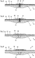
- FIG. 1 shows a part of a manufacturing mold 10 for producing a wind turbine component 12 (see, eg FIG. 8 ) in cross section.
- the production mold 10 consists essentially of a fiber composite material 14 and has an inner side 16.
- a sleeve 18 made of metal which has a flange-shaped portion 20, the end face is approximately flush with the inner side 16 of the manufacturing mold 10.
- the sleeve 18 is only covered by a thin resin layer 46.
- a blind bore 22 is formed, which has a not-shown internal thread.
- the sleeve 18 forms a receptacle of the manufacturing mold 10.
- In an environment of the sleeve 18 of the fiber composite material 14 of the manufacturing mold 10 is designed with a greater material thickness to form a reinforcement for firmly anchoring the sleeve 18.
- FIG. 2 shows the in FIG. 1 provided manufacturing mold 10 after inserting a first portion 26 of a positioning pin 24 in the formed by the sleeve 18 receiving the manufacturing mold 10.
- the positioning pin 24 is in the example of metal and has an elongated cylindrical shape. He has in the region of the first portion 26 an unillustrated external thread, which is screwed into the internal thread of the blind bore 22. A second portion 28 of the positioning pin protrudes from the inside 16 of the manufacturing mold 10. He also has an unillustrated external thread.
- a release agent is first applied to the inside 16 of the manufacturing mold 10, then a gelcoat layer 30, which in the FIG. 3 is shown.
- the gelcoat layer 30 later forms an outer surface of the wind turbine component 12 to be produced.
- reinforcing fibers 32 arranged in the manufacturing mold 10.
- pre-impregnated with a liquid plastic material reinforcing fibers so-called prepregs, are inserted into the mold, or dry reinforcing fibers, in particular in the form of loops or fabrics or other fiber mats.
- the reinforcing fibers 32 are guided around the positioning pin 24 so that they are not severed in the region of the positioning pin 24.
- FIG. 5 shows the assembly from the FIG. 4 after placing a prefabricated component 34 in the production mold 10.
- the prefabricated component 34 is a steel insert which has a passage opening 36 with an internal thread, not shown.
- the passage opening 36 forms a receptacle of the prefabricated component 34 for the second portion 28 of the positioning pin 24.
- the prefabricated component 34 is screwed with this receptacle on the second portion 28 of the positioning pin 24 until it is at the desired distance from the inside 16 of the manufacturing mold 10 is located.
- a part of the reinforcing fibers 32 is arranged between the prefabricated component 34 and the inner side 16 of the production mold 10.
- FIG. 6 shows that the prefabricated component 34 has subsequently been covered with further layers of reinforcing fibers 38, which rest against the previously inserted reinforcing fibers 32, so that the prefabricated component 34 is surrounded on all sides by the reinforcing fibers 32 and 38, respectively.
- the reinforcing fibers 32 and 38 have been introduced in dry form into the manufacturing mold 10, they are now impregnated with a liquid plastic material. This can be done, for example, after an airtight sealing of the production mold 10 in a vacuum infusion process. Likewise it is possible to apply the liquid plastic material by hand lamination. The reinforcing fibers 32, 38 and the prefabricated component 34 are then embedded in the liquid plastic material. The arrangement of the prefabricated component 34 relative to the manufacturing mold 10 is predetermined by the positioning pin 24 and remains unchanged during curing of the liquid plastic material.
- the positioning pin 24 can be removed, so that the arrangement of the FIG. 7 results.
- the positioning pin 24 can be unscrewed in the simplest case from the internal threads in the receptacle of the manufacturing mold 10 and in the receptacle of the prefabricated component 34.
- FIG. 8 shows the completed wind turbine component 12 after demolding.
- the manufacturing mold 10 can then be used to manufacture further wind turbine components 12.
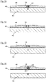
- FIGS. 9 to 16 two different methods explained, with which the production mold 10 of the method according to the invention can be produced.
- a master model 40 created whose shape corresponds to the manufactured wind turbine component 12.
- the master model 40 is a positive form.
- the master model 40 is provided on an outer side 50 with a guide bore 42 into which, as in the FIG. 10 shown, a positioning pin 44 is inserted, so that the positioning pin 44 protrudes partially from the master model 40.
- the outer side 50 of the master model 40 is provided with a release agent and it is applied as a first layer of the manufacturing mold 10 to be produced, a fine resin layer 46. This is in the FIG. 11 shown.
- a sleeve 18 is disposed on the positioning pin 44, which forms a receptacle of the manufacturing mold 10 later.
- FIG. 13 shows the further completion of the production mold 10.
- several layers of reinforcing fibers 48 are processed in the lamination process.
- the positioning pin 44 is removed, so that in the FIG. 14 shown arrangement results. Subsequently, the manufacturing mold 10 is separated from the master model 40, as in the FIG. 15 shown.
- the positioning pin 44 are destroyed when separating the manufacturing mold 10 from the master model 40, in particular in the region of a predetermined breaking point.
- the recording of the manufacturing mold 10 may be closed, in particular on its side facing away from the inside 16 of the manufacturing mold 10 side, for example, as in the FIG. 16 shown using a sleeve 18 in which a blind bore 22 is formed.
Landscapes
- Engineering & Computer Science (AREA)
- Mechanical Engineering (AREA)
- Chemical & Material Sciences (AREA)
- Composite Materials (AREA)
- Wind Motors (AREA)
- Moulding By Coating Moulds (AREA)
Priority Applications (3)
| Application Number | Priority Date | Filing Date | Title |
|---|---|---|---|
| ES15159245T ES2739645T3 (es) | 2015-03-16 | 2015-03-16 | Procedimiento y dispositivo para la producción de un componente de turbina eólica de un material compuesto de fibras |
| EP15159245.8A EP3069858B1 (de) | 2015-03-16 | 2015-03-16 | Verfahren und Vorrichtung zur Herstellung eines Windenergieanlagenbauteils aus einem Faserverbundwerkstoff |
| DK15159245.8T DK3069858T3 (da) | 2015-03-16 | 2015-03-16 | Fremgangsmåde og apparat til fremstilling af en vindenergianlægs-kon-struktionsdel af et fiberkompositmateriale |
Applications Claiming Priority (1)
| Application Number | Priority Date | Filing Date | Title |
|---|---|---|---|
| EP15159245.8A EP3069858B1 (de) | 2015-03-16 | 2015-03-16 | Verfahren und Vorrichtung zur Herstellung eines Windenergieanlagenbauteils aus einem Faserverbundwerkstoff |
Publications (2)
| Publication Number | Publication Date |
|---|---|
| EP3069858A1 EP3069858A1 (de) | 2016-09-21 |
| EP3069858B1 true EP3069858B1 (de) | 2019-06-26 |
Family
ID=52686177
Family Applications (1)
| Application Number | Title | Priority Date | Filing Date |
|---|---|---|---|
| EP15159245.8A Active EP3069858B1 (de) | 2015-03-16 | 2015-03-16 | Verfahren und Vorrichtung zur Herstellung eines Windenergieanlagenbauteils aus einem Faserverbundwerkstoff |
Country Status (3)
| Country | Link |
|---|---|
| EP (1) | EP3069858B1 (da) |
| DK (1) | DK3069858T3 (da) |
| ES (1) | ES2739645T3 (da) |
Cited By (1)
| Publication number | Priority date | Publication date | Assignee | Title |
|---|---|---|---|---|
| EP4284628A4 (en) * | 2021-02-01 | 2024-12-18 | TPI Composites, Inc. | WIND TURBINE BLADE SHAPE WITH INTEGRATED GEOMETRIC REFERENCES ON B-SURFACE |
Families Citing this family (6)
| Publication number | Priority date | Publication date | Assignee | Title |
|---|---|---|---|---|
| CN108819290B (zh) * | 2018-06-08 | 2021-01-19 | 连云港中复连众复合材料集团有限公司 | 风力叶片前缘粘贴角模具定位装置及其制作方法 |
| CN113165285A (zh) * | 2018-12-11 | 2021-07-23 | 通用电气公司 | 用于制造用于风力涡轮的转子叶片的叶片节段的结构构件的方法 |
| WO2020122870A1 (en) * | 2018-12-11 | 2020-06-18 | General Electric Company | Method for manufacturing a structural component of a blade segment for a rotor blade of a wind turbine |
| CN113858650B (zh) * | 2020-06-30 | 2024-05-24 | 中国航发商用航空发动机有限责任公司 | 制造复合材料环形件的方法 |
| CN113954391B (zh) * | 2021-10-13 | 2024-03-12 | 上海复合材料科技有限公司 | S形复合材料进气道成型模及其制备方法 |
| CN119458704B (zh) * | 2024-12-26 | 2025-10-10 | 哈尔滨玻璃钢研究院有限公司 | 一种框架式立体结构复合材料成型模具及其成型方法 |
Family Cites Families (2)
| Publication number | Priority date | Publication date | Assignee | Title |
|---|---|---|---|---|
| WO2006070171A1 (en) * | 2004-12-29 | 2006-07-06 | Vestas Wind Systems A/S | Method of manufacturing a wind turbine blade shell member with a fastening member and a wind turbine blade with a fastening member |
| EP2662204A1 (de) | 2012-05-07 | 2013-11-13 | Nordex Energy GmbH | Verfahren, vorgefertiges Bauelement und Form zur Herstellung eines Windenergieanlagenbauteils |
-
2015
- 2015-03-16 EP EP15159245.8A patent/EP3069858B1/de active Active
- 2015-03-16 ES ES15159245T patent/ES2739645T3/es active Active
- 2015-03-16 DK DK15159245.8T patent/DK3069858T3/da active
Non-Patent Citations (1)
| Title |
|---|
| None * |
Cited By (1)
| Publication number | Priority date | Publication date | Assignee | Title |
|---|---|---|---|---|
| EP4284628A4 (en) * | 2021-02-01 | 2024-12-18 | TPI Composites, Inc. | WIND TURBINE BLADE SHAPE WITH INTEGRATED GEOMETRIC REFERENCES ON B-SURFACE |
Also Published As
| Publication number | Publication date |
|---|---|
| ES2739645T3 (es) | 2020-02-03 |
| EP3069858A1 (de) | 2016-09-21 |
| DK3069858T3 (da) | 2019-10-07 |
Similar Documents
| Publication | Publication Date | Title |
|---|---|---|
| EP3069858A1 (de) | Verfahren und Vorrichtung zur Herstellung eines Windenergieanlagenbauteils aus einem Faserverbundwerkstoff | |
| DE102011079240B4 (de) | Einrichtung und Verfahren zur Fertigung eines Bauteils | |
| EP2666615B1 (de) | Verfahren zur Herstellung einer Windenergieanlagenrotorblatthalbschale bzw. eines Windenergieanlagenrotorblatts und Herstellungsform zu diesem Zweck | |
| DE102009047671A1 (de) | Verfahren zum Anbinden eines Faserverbundbauteils an ein Strukturbauteil eines Luft- und Raumfahrzeuges und eine entsprechende Anordnung | |
| DE102008021498A1 (de) | Verfahren zur Fertigung eines Blattanschlusses eines Rotorblatts, ein Blattanschluss und ein Befestigungselement für einen Blattanschluss | |
| DE102009024973B4 (de) | Verfahren zum Herstellen eines schalenförmigen Bauteils | |
| DE102010042128A1 (de) | Strukturbauteil, Luft- oder Raumfahrzeug sowie Verfahren | |
| EP3339633B1 (de) | Verfahren zur herstellung einer potentialausgleichsverbindung an einem windenergieanlagenrotorblatt | |
| WO2014121992A1 (de) | Verfahren zur herstellung eines faserverstärkten kunststoffbauteils | |
| EP2662204A1 (de) | Verfahren, vorgefertiges Bauelement und Form zur Herstellung eines Windenergieanlagenbauteils | |
| EP3634730B1 (de) | Verfahren zum herstellen eines windenergieanlagen-rotorblattes | |
| DE102007003273A1 (de) | Lokalisierte Bearbeitung von verstärkten Schaumwerkstoffen sowie Kernverbundbauteil | |
| EP3489000A1 (de) | Verfahren zum herstellen eines faserverbundbauteils | |
| DE102014017200A1 (de) | Verfahren zur Herstellung von Faserverbundteilen und ein Faserverbundteil | |
| EP2926990B1 (de) | Verfahren zum bereitstellen von abstandshaltern | |
| EP3418040A1 (de) | Pultrudiertes profil mit abreissgewebe | |
| DE102012013538A1 (de) | Verfahren und Vorrichtung zur Herstellung von Sandwichelementen | |
| DE102017128501A1 (de) | Verfahren zum Herstellen eines Verbundbauteils | |
| DE102011117185A1 (de) | Haltevorrichtung zur Anbringung mindestens eines Anbauteils an eine Rumpfzellenstruktur eines Luftfahrzeuges | |
| DE102015201348A1 (de) | Verfahren zum Ausbilden eines Funktionsabschnitts an einem Faserverbundbauteil | |
| DE102010032095A1 (de) | Verfahren und Vorrichtung zum Herstellen eines Dekorteils | |
| DE102013018530B4 (de) | Vorlochfrei schraubgefügter Bauteilverbund mit wenigstens einem FVK-Bauteil und wenigstens einem Blechbauteil, sowie Verfahren zur Herstellung des FVK-Bauteils und des Bauteilverbunds | |
| DE102015119401A1 (de) | Verfahren zur Herstellung eines Sandwichbauteils | |
| EP3647039B1 (de) | Verfahren zum herstellen eines bereichsweise flächigen bauteils aus einem faserverbundwerkstoff | |
| DE102018009379A1 (de) | Neues Verfahren zum Herstellen eines bereichsweise flächigen Bauteils aus einem Faserverbundwerkstoff |
Legal Events
| Date | Code | Title | Description |
|---|---|---|---|
| PUAI | Public reference made under article 153(3) epc to a published international application that has entered the european phase |
Free format text: ORIGINAL CODE: 0009012 |
|
| AK | Designated contracting states |
Kind code of ref document: A1 Designated state(s): AL AT BE BG CH CY CZ DE DK EE ES FI FR GB GR HR HU IE IS IT LI LT LU LV MC MK MT NL NO PL PT RO RS SE SI SK SM TR |
|
| AX | Request for extension of the european patent |
Extension state: BA ME |
|
| STAA | Information on the status of an ep patent application or granted ep patent |
Free format text: STATUS: REQUEST FOR EXAMINATION WAS MADE |
|
| 17P | Request for examination filed |
Effective date: 20170316 |
|
| RBV | Designated contracting states (corrected) |
Designated state(s): AL AT BE BG CH CY CZ DE DK EE ES FI FR GB GR HR HU IE IS IT LI LT LU LV MC MK MT NL NO PL PT RO RS SE SI SK SM TR |
|
| GRAP | Despatch of communication of intention to grant a patent |
Free format text: ORIGINAL CODE: EPIDOSNIGR1 |
|
| STAA | Information on the status of an ep patent application or granted ep patent |
Free format text: STATUS: GRANT OF PATENT IS INTENDED |
|
| INTG | Intention to grant announced |
Effective date: 20190417 |
|
| GRAS | Grant fee paid |
Free format text: ORIGINAL CODE: EPIDOSNIGR3 |
|
| GRAA | (expected) grant |
Free format text: ORIGINAL CODE: 0009210 |
|
| STAA | Information on the status of an ep patent application or granted ep patent |
Free format text: STATUS: THE PATENT HAS BEEN GRANTED |
|
| AK | Designated contracting states |
Kind code of ref document: B1 Designated state(s): AL AT BE BG CH CY CZ DE DK EE ES FI FR GB GR HR HU IE IS IT LI LT LU LV MC MK MT NL NO PL PT RO RS SE SI SK SM TR |
|
| REG | Reference to a national code |
Ref country code: GB Ref legal event code: FG4D Free format text: NOT ENGLISH |
|
| REG | Reference to a national code |
Ref country code: CH Ref legal event code: EP |
|
| REG | Reference to a national code |
Ref country code: DE Ref legal event code: R096 Ref document number: 502015009417 Country of ref document: DE |
|
| REG | Reference to a national code |
Ref country code: AT Ref legal event code: REF Ref document number: 1147802 Country of ref document: AT Kind code of ref document: T Effective date: 20190715 |
|
| REG | Reference to a national code |
Ref country code: IE Ref legal event code: FG4D Free format text: LANGUAGE OF EP DOCUMENT: GERMAN |
|
| REG | Reference to a national code |
Ref country code: DK Ref legal event code: T3 Effective date: 20191003 |
|
| REG | Reference to a national code |
Ref country code: NL Ref legal event code: MP Effective date: 20190626 |
|
| PG25 | Lapsed in a contracting state [announced via postgrant information from national office to epo] |
Ref country code: FI Free format text: LAPSE BECAUSE OF FAILURE TO SUBMIT A TRANSLATION OF THE DESCRIPTION OR TO PAY THE FEE WITHIN THE PRESCRIBED TIME-LIMIT Effective date: 20190626 Ref country code: LT Free format text: LAPSE BECAUSE OF FAILURE TO SUBMIT A TRANSLATION OF THE DESCRIPTION OR TO PAY THE FEE WITHIN THE PRESCRIBED TIME-LIMIT Effective date: 20190626 Ref country code: SE Free format text: LAPSE BECAUSE OF FAILURE TO SUBMIT A TRANSLATION OF THE DESCRIPTION OR TO PAY THE FEE WITHIN THE PRESCRIBED TIME-LIMIT Effective date: 20190626 Ref country code: NO Free format text: LAPSE BECAUSE OF FAILURE TO SUBMIT A TRANSLATION OF THE DESCRIPTION OR TO PAY THE FEE WITHIN THE PRESCRIBED TIME-LIMIT Effective date: 20190926 Ref country code: HR Free format text: LAPSE BECAUSE OF FAILURE TO SUBMIT A TRANSLATION OF THE DESCRIPTION OR TO PAY THE FEE WITHIN THE PRESCRIBED TIME-LIMIT Effective date: 20190626 Ref country code: AL Free format text: LAPSE BECAUSE OF FAILURE TO SUBMIT A TRANSLATION OF THE DESCRIPTION OR TO PAY THE FEE WITHIN THE PRESCRIBED TIME-LIMIT Effective date: 20190626 |
|
| REG | Reference to a national code |
Ref country code: LT Ref legal event code: MG4D |
|
| PG25 | Lapsed in a contracting state [announced via postgrant information from national office to epo] |
Ref country code: BG Free format text: LAPSE BECAUSE OF FAILURE TO SUBMIT A TRANSLATION OF THE DESCRIPTION OR TO PAY THE FEE WITHIN THE PRESCRIBED TIME-LIMIT Effective date: 20190926 Ref country code: RS Free format text: LAPSE BECAUSE OF FAILURE TO SUBMIT A TRANSLATION OF THE DESCRIPTION OR TO PAY THE FEE WITHIN THE PRESCRIBED TIME-LIMIT Effective date: 20190626 Ref country code: LV Free format text: LAPSE BECAUSE OF FAILURE TO SUBMIT A TRANSLATION OF THE DESCRIPTION OR TO PAY THE FEE WITHIN THE PRESCRIBED TIME-LIMIT Effective date: 20190626 Ref country code: GR Free format text: LAPSE BECAUSE OF FAILURE TO SUBMIT A TRANSLATION OF THE DESCRIPTION OR TO PAY THE FEE WITHIN THE PRESCRIBED TIME-LIMIT Effective date: 20190927 |
|
| PG25 | Lapsed in a contracting state [announced via postgrant information from national office to epo] |
Ref country code: EE Free format text: LAPSE BECAUSE OF FAILURE TO SUBMIT A TRANSLATION OF THE DESCRIPTION OR TO PAY THE FEE WITHIN THE PRESCRIBED TIME-LIMIT Effective date: 20190626 Ref country code: SK Free format text: LAPSE BECAUSE OF FAILURE TO SUBMIT A TRANSLATION OF THE DESCRIPTION OR TO PAY THE FEE WITHIN THE PRESCRIBED TIME-LIMIT Effective date: 20190626 Ref country code: PT Free format text: LAPSE BECAUSE OF FAILURE TO SUBMIT A TRANSLATION OF THE DESCRIPTION OR TO PAY THE FEE WITHIN THE PRESCRIBED TIME-LIMIT Effective date: 20191028 Ref country code: CZ Free format text: LAPSE BECAUSE OF FAILURE TO SUBMIT A TRANSLATION OF THE DESCRIPTION OR TO PAY THE FEE WITHIN THE PRESCRIBED TIME-LIMIT Effective date: 20190626 Ref country code: NL Free format text: LAPSE BECAUSE OF FAILURE TO SUBMIT A TRANSLATION OF THE DESCRIPTION OR TO PAY THE FEE WITHIN THE PRESCRIBED TIME-LIMIT Effective date: 20190626 Ref country code: RO Free format text: LAPSE BECAUSE OF FAILURE TO SUBMIT A TRANSLATION OF THE DESCRIPTION OR TO PAY THE FEE WITHIN THE PRESCRIBED TIME-LIMIT Effective date: 20190626 |
|
| REG | Reference to a national code |
Ref country code: ES Ref legal event code: FG2A Ref document number: 2739645 Country of ref document: ES Kind code of ref document: T3 Effective date: 20200203 |
|
| PG25 | Lapsed in a contracting state [announced via postgrant information from national office to epo] |
Ref country code: SM Free format text: LAPSE BECAUSE OF FAILURE TO SUBMIT A TRANSLATION OF THE DESCRIPTION OR TO PAY THE FEE WITHIN THE PRESCRIBED TIME-LIMIT Effective date: 20190626 Ref country code: IT Free format text: LAPSE BECAUSE OF FAILURE TO SUBMIT A TRANSLATION OF THE DESCRIPTION OR TO PAY THE FEE WITHIN THE PRESCRIBED TIME-LIMIT Effective date: 20190626 Ref country code: IS Free format text: LAPSE BECAUSE OF FAILURE TO SUBMIT A TRANSLATION OF THE DESCRIPTION OR TO PAY THE FEE WITHIN THE PRESCRIBED TIME-LIMIT Effective date: 20191026 |
|
| PG25 | Lapsed in a contracting state [announced via postgrant information from national office to epo] |
Ref country code: TR Free format text: LAPSE BECAUSE OF FAILURE TO SUBMIT A TRANSLATION OF THE DESCRIPTION OR TO PAY THE FEE WITHIN THE PRESCRIBED TIME-LIMIT Effective date: 20190626 |
|
| PG25 | Lapsed in a contracting state [announced via postgrant information from national office to epo] |
Ref country code: PL Free format text: LAPSE BECAUSE OF FAILURE TO SUBMIT A TRANSLATION OF THE DESCRIPTION OR TO PAY THE FEE WITHIN THE PRESCRIBED TIME-LIMIT Effective date: 20190626 |
|
| PG25 | Lapsed in a contracting state [announced via postgrant information from national office to epo] |
Ref country code: IS Free format text: LAPSE BECAUSE OF FAILURE TO SUBMIT A TRANSLATION OF THE DESCRIPTION OR TO PAY THE FEE WITHIN THE PRESCRIBED TIME-LIMIT Effective date: 20200224 |
|
| REG | Reference to a national code |
Ref country code: DE Ref legal event code: R097 Ref document number: 502015009417 Country of ref document: DE |
|
| PLBE | No opposition filed within time limit |
Free format text: ORIGINAL CODE: 0009261 |
|
| STAA | Information on the status of an ep patent application or granted ep patent |
Free format text: STATUS: NO OPPOSITION FILED WITHIN TIME LIMIT |
|
| PG2D | Information on lapse in contracting state deleted |
Ref country code: IS |
|
| 26N | No opposition filed |
Effective date: 20200603 |
|
| PG25 | Lapsed in a contracting state [announced via postgrant information from national office to epo] |
Ref country code: SI Free format text: LAPSE BECAUSE OF FAILURE TO SUBMIT A TRANSLATION OF THE DESCRIPTION OR TO PAY THE FEE WITHIN THE PRESCRIBED TIME-LIMIT Effective date: 20190626 |
|
| PG25 | Lapsed in a contracting state [announced via postgrant information from national office to epo] |
Ref country code: MC Free format text: LAPSE BECAUSE OF FAILURE TO SUBMIT A TRANSLATION OF THE DESCRIPTION OR TO PAY THE FEE WITHIN THE PRESCRIBED TIME-LIMIT Effective date: 20190626 |
|
| REG | Reference to a national code |
Ref country code: CH Ref legal event code: PL |
|
| REG | Reference to a national code |
Ref country code: BE Ref legal event code: MM Effective date: 20200331 |
|
| PG25 | Lapsed in a contracting state [announced via postgrant information from national office to epo] |
Ref country code: LU Free format text: LAPSE BECAUSE OF NON-PAYMENT OF DUE FEES Effective date: 20200316 |
|
| PG25 | Lapsed in a contracting state [announced via postgrant information from national office to epo] |
Ref country code: LI Free format text: LAPSE BECAUSE OF NON-PAYMENT OF DUE FEES Effective date: 20200331 Ref country code: IE Free format text: LAPSE BECAUSE OF NON-PAYMENT OF DUE FEES Effective date: 20200316 Ref country code: CH Free format text: LAPSE BECAUSE OF NON-PAYMENT OF DUE FEES Effective date: 20200331 Ref country code: FR Free format text: LAPSE BECAUSE OF NON-PAYMENT OF DUE FEES Effective date: 20200331 |
|
| REG | Reference to a national code |
Ref country code: DE Ref legal event code: R082 Ref document number: 502015009417 Country of ref document: DE Representative=s name: HAUCK PATENT- UND RECHTSANWAELTE PARTMBB, DE Ref country code: DE Ref legal event code: R082 Ref document number: 502015009417 Country of ref document: DE Representative=s name: HAUCK PATENTANWALTSPARTNERSCHAFT MBB, DE Ref country code: DE Ref legal event code: R081 Ref document number: 502015009417 Country of ref document: DE Owner name: NORDEX ENERGY SE & CO. KG, DE Free format text: FORMER OWNER: NORDEX ENERGY GMBH, 22419 HAMBURG, DE |
|
| PG25 | Lapsed in a contracting state [announced via postgrant information from national office to epo] |
Ref country code: BE Free format text: LAPSE BECAUSE OF NON-PAYMENT OF DUE FEES Effective date: 20200331 |
|
| GBPC | Gb: european patent ceased through non-payment of renewal fee |
Effective date: 20200316 |
|
| PG25 | Lapsed in a contracting state [announced via postgrant information from national office to epo] |
Ref country code: GB Free format text: LAPSE BECAUSE OF NON-PAYMENT OF DUE FEES Effective date: 20200316 |
|
| REG | Reference to a national code |
Ref country code: AT Ref legal event code: MM01 Ref document number: 1147802 Country of ref document: AT Kind code of ref document: T Effective date: 20200316 |
|
| PG25 | Lapsed in a contracting state [announced via postgrant information from national office to epo] |
Ref country code: AT Free format text: LAPSE BECAUSE OF NON-PAYMENT OF DUE FEES Effective date: 20200316 |
|
| PG25 | Lapsed in a contracting state [announced via postgrant information from national office to epo] |
Ref country code: MT Free format text: LAPSE BECAUSE OF FAILURE TO SUBMIT A TRANSLATION OF THE DESCRIPTION OR TO PAY THE FEE WITHIN THE PRESCRIBED TIME-LIMIT Effective date: 20190626 Ref country code: CY Free format text: LAPSE BECAUSE OF FAILURE TO SUBMIT A TRANSLATION OF THE DESCRIPTION OR TO PAY THE FEE WITHIN THE PRESCRIBED TIME-LIMIT Effective date: 20190626 |
|
| PG25 | Lapsed in a contracting state [announced via postgrant information from national office to epo] |
Ref country code: MK Free format text: LAPSE BECAUSE OF FAILURE TO SUBMIT A TRANSLATION OF THE DESCRIPTION OR TO PAY THE FEE WITHIN THE PRESCRIBED TIME-LIMIT Effective date: 20190626 |
|
| P01 | Opt-out of the competence of the unified patent court (upc) registered |
Effective date: 20230602 |
|
| PGFP | Annual fee paid to national office [announced via postgrant information from national office to epo] |
Ref country code: ES Payment date: 20250416 Year of fee payment: 11 |
|
| PGFP | Annual fee paid to national office [announced via postgrant information from national office to epo] |
Ref country code: DE Payment date: 20260320 Year of fee payment: 12 Ref country code: DK Payment date: 20260323 Year of fee payment: 12 |