EP3070017B1 - Verpackungselement und rohling für das verpackungselement mit perfektionierter verkeilvorrichtung - Google Patents
Verpackungselement und rohling für das verpackungselement mit perfektionierter verkeilvorrichtung Download PDFInfo
- Publication number
- EP3070017B1 EP3070017B1 EP16160763.5A EP16160763A EP3070017B1 EP 3070017 B1 EP3070017 B1 EP 3070017B1 EP 16160763 A EP16160763 A EP 16160763A EP 3070017 B1 EP3070017 B1 EP 3070017B1
- Authority
- EP
- European Patent Office
- Prior art keywords
- main
- panel
- longitudinal
- panels
- transverse
- Prior art date
- Legal status (The legal status is an assumption and is not a legal conclusion. Google has not performed a legal analysis and makes no representation as to the accuracy of the status listed.)
- Active
Links
Images






Classifications
-
- B—PERFORMING OPERATIONS; TRANSPORTING
- B65—CONVEYING; PACKING; STORING; HANDLING THIN OR FILAMENTARY MATERIAL
- B65D—CONTAINERS FOR STORAGE OR TRANSPORT OF ARTICLES OR MATERIALS, e.g. BAGS, BARRELS, BOTTLES, BOXES, CANS, CARTONS, CRATES, DRUMS, JARS, TANKS, HOPPERS, FORWARDING CONTAINERS; ACCESSORIES, CLOSURES, OR FITTINGS THEREFOR; PACKAGING ELEMENTS; PACKAGES
- B65D5/00—Rigid or semi-rigid containers of polygonal cross-section, e.g. boxes, cartons or trays, formed by folding or erecting one or more blanks made of paper
- B65D5/42—Details of containers or of foldable or erectable container blanks
- B65D5/44—Integral, inserted or attached portions forming internal or external fittings
- B65D5/50—Internal supporting or protecting elements for contents
- B65D5/5002—Integral elements for containers having tubular body walls
- B65D5/5016—Integral elements for containers having tubular body walls formed by folding inwardly of extensions hinged to the side edges of the body
-
- B—PERFORMING OPERATIONS; TRANSPORTING
- B65—CONVEYING; PACKING; STORING; HANDLING THIN OR FILAMENTARY MATERIAL
- B65D—CONTAINERS FOR STORAGE OR TRANSPORT OF ARTICLES OR MATERIALS, e.g. BAGS, BARRELS, BOTTLES, BOXES, CANS, CARTONS, CRATES, DRUMS, JARS, TANKS, HOPPERS, FORWARDING CONTAINERS; ACCESSORIES, CLOSURES, OR FITTINGS THEREFOR; PACKAGING ELEMENTS; PACKAGES
- B65D5/00—Rigid or semi-rigid containers of polygonal cross-section, e.g. boxes, cartons or trays, formed by folding or erecting one or more blanks made of paper
- B65D5/02—Rigid or semi-rigid containers of polygonal cross-section, e.g. boxes, cartons or trays, formed by folding or erecting one or more blanks made of paper by folding or erecting a single blank to form a tubular body with or without subsequent folding operations, or the addition of separate elements, to close the ends of the body
- B65D5/0254—Rigid or semi-rigid containers of polygonal cross-section, e.g. boxes, cartons or trays, formed by folding or erecting one or more blanks made of paper by folding or erecting a single blank to form a tubular body with or without subsequent folding operations, or the addition of separate elements, to close the ends of the body with end closures formed by inward folding of flaps and securing them by means of a tongue integral with one of the flaps
-
- B—PERFORMING OPERATIONS; TRANSPORTING
- B65—CONVEYING; PACKING; STORING; HANDLING THIN OR FILAMENTARY MATERIAL
- B65D—CONTAINERS FOR STORAGE OR TRANSPORT OF ARTICLES OR MATERIALS, e.g. BAGS, BARRELS, BOTTLES, BOXES, CANS, CARTONS, CRATES, DRUMS, JARS, TANKS, HOPPERS, FORWARDING CONTAINERS; ACCESSORIES, CLOSURES, OR FITTINGS THEREFOR; PACKAGING ELEMENTS; PACKAGES
- B65D5/00—Rigid or semi-rigid containers of polygonal cross-section, e.g. boxes, cartons or trays, formed by folding or erecting one or more blanks made of paper
- B65D5/42—Details of containers or of foldable or erectable container blanks
- B65D5/44—Integral, inserted or attached portions forming internal or external fittings
- B65D5/50—Internal supporting or protecting elements for contents
- B65D5/5028—Elements formed separately from the container body
- B65D5/5035—Paper elements
- B65D5/5045—Tubular lining and supporting elements
Definitions
- the invention relates to the field of packaging and more particularly the field of packaging obtained from a single blank, pre-cut and folded from a sheet of material, in particular from a sheet of cardboard.
- Such packages are very widely used in many fields for packaging products, for example cosmetics or perfumery products.
- These products may for example be containers, especially tubes, flasks, etc.
- Such containers contain substances that may be in the form of fluids, pastes, powders, granules, etc.
- the packages according to the invention therefore comprise at least one peripheral envelope formed of at least three peripheral panels articulated successively to one another around longitudinal fold lines which extend in the longitudinal direction, parallel to one another. the other.
- the fold lines define longitudinal sides of the peripheral panels.
- the peripheral envelope is closed on itself to define a closed contour around an interior space in a transverse plane perpendicular to the longitudinal direction of the fold lines.
- at least one of the extreme peripheral panels is provided with an assembly flap, also articulated to the end peripheral panel by a longitudinal fold line, to be pressed against an inner or outer face of the other extreme peripheral panel to achieve an assembly, for example by gluing, to form the peripheral envelope.
- the interior space defined by such a peripheral envelope is closed in at least two directions perpendicular to the longitudinal direction. But it is generally still necessary to provide means to ensure the longitudinal locking of the product in the peripheral envelope, in at least one direction in the longitudinal direction.
- the peripheral envelope defines an outer envelope and is provided with closure flaps which are articulated to one of the peripheral panels by a transverse fold line.
- Such shutters can be provided at one and the other of the longitudinal ends of the outer peripheral envelope.
- closure flaps have a shape corresponding to the shape of the closed contour of the outer peripheral envelope and, once folded, often at 90 °, they respectively close the interior space longitudinally to one and the other both ends of the interior space.
- the outer peripheral envelope is not provided with closure flaps, at least not at both longitudinal ends, but is optionally provided with product locking means in the longitudinal direction in space inside.
- product locking means in the longitudinal direction in space inside.
- tab systems each tab being connected to a transverse longitudinal end edge of one of the peripheral panels.
- Such tongues are for example folded inwards and then form harpoons which allow the introduction of the product inside the interior space, but which then cooperate with this product to prevent the withdrawal of the product from the packaging , except to deform or irreparably tear the tabs forming harpoons.
- Some packages comprise on the one hand an outer envelope as described above and a wedging element which is received inside the outer casing, the outer casing and the wedging element being both obtained to from the same single blank pre-cut and folded from a sheet of material.
- a wedging element also comprises a main peripheral envelope comprising at least three main panels successively articulated to each other around longitudinal fold lines which extend parallel to one another in a longitudinal direction. The fold lines define longitudinal sides of the main panels and the main envelope thus formed is closed on itself to also define a closed wedging contour around an internal wedging space.
- the wedging element is received inside the interior space of the outer envelope.
- the product is received inside the interior space of the wedging element.
- the wedging element has as many main panels as there are peripheral panels in the external envelope.
- support lugs are provided between the outer casing and the main casing of the wedging element to maintain a relative position between the two casings, in the two transverse directions perpendicular to the longitudinal direction. It is understood that a package comprising both an outer envelope and a wedging element, obtained from the same single blank, is already a complex object, both in its design and in its manufacture by folding and assembling the single blank .
- the document GB-365.78 describes a centering system which is elastic which acts transversely.
- Other locking systems are known to US 4,445,613 and DE 20 2011 106417 U .
- the invention therefore aims to propose a new design of a packaging or packaging element, and a blank to obtain this packaging or packaging element, which provides a solution to at least some aspects of this problem. wedging in the longitudinal direction.
- Each connecting lug comprises an intermediate transverse folding line which delimits a main portion and an end portion of the connecting lug, respectively attached to the corresponding main panel and to the end panel, so as to bring the band of end of the main casing by folding the two parts of the connecting lug on themselves around the intermediate fold line.
- the main part of the connecting lug is hinged to the corresponding main panel by a pre-marked transverse fold line.
- the end wedging device is a bi-articulated device in which the end portion of said at least two connecting lugs is attached to the corresponding end panel by a deflection free flexion zone. of pre-marked folding cross line.
- Each connecting lug comprises an intermediate transverse folding line which delimits a main portion and an end portion of the connecting lug, respectively attached to the corresponding main panel and to the end panel, so as to bring the band of end of the main envelope by folding the two parts of the connecting lug on themselves around the intermediate fold line, and of the type in which the main part of the connecting lug is hinged to the corresponding main panel by a pre-marked transverse folding line.
- the end wedging device is a bi-articulated device in which the end portion of said at least two connecting lugs is attached to the corresponding end panel by a bending zone devoid of pre-marked transverse folding line. .
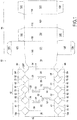
- FIG. 1 a first embodiment of a blank 10 according to the invention for obtaining a package according to the invention.
- the blank 10 which is illustrated on the Figure 1 is obtained by cutting a sheet of material and constitutes a single blank in that there is continuity of material in the blank, which is not constituted by an assembly of several previously disjoint elements.
- the blank material will be a conventional material for this type of packaging. It may for example be a cardboard whose weight is greater than or equal to 180 g per square meter. Generally, the cardboard used for such packages has a basis weight less than or equal to 2000 g per square meter. However, the use of other materials, including polymeric materials, is conceivable. Preferably, these materials have a semi-rigid appearance flexion about an axis in the plane of the sheet in which the blank is pre-cut.
- markings are intended to form a pre-marked fold line of the sheet of material for the purpose of producing the package.
- the blank 10 which is planar, must be subjected to folding operations and assembly, including gluing, to achieve a three-dimensional packaging.
- the blank 10 has two main portions each intended to form a peripheral envelope.
- a first portion 12, visible on the left of the Figure 1 and visible on the Figure 2 is intended to form a main element, called wedging element, packaging.
- a second portion 14, visible on the right side of the Figure 1 is intended to form an outer envelope of the package.
- the two portions 12, 14 of the blank 10 are connected to each other by a connecting panel 16 whose role will be explained later.
- the blank comprises four main panels 21, 22, 23, 24 which are juxtaposed and articulated successively to one another around three fold lines 31, 32, 33 longitudinal.
- a first fold line 31 connects, delimiting, a distal extreme main panel 21 of a distal intermediate main panel 22.
- a second fold line 32 connects the distal intermediate main panel 22 to a proximal intermediate main panel 23, which is connected to a proximal proximal main panel 24 around a fold line 33.
- the fold lines 31, 32, 33 thus define longitudinal sides of the corresponding main panels.
- the distal endmost main panel 21 further comprises a longitudinal side 30 through which it is connected to an assembly flap 18, the longitudinal side 30 corresponding to a fold line, preferably pre-marked, between the panel 21 and the flap 18.
- the flap 18 has a longitudinal free edge 29, which is a free edge of the blank 10.
- the proximal end main panel 24 has, opposite the longitudinal side 33, a longitudinal side 34 which, in this embodiment, is formed of a pre-marked fold line by which it is connected to the connecting panel 16 .
- the main panels have transverse extensions 51, 52, 53, 54, 55 arranged at the longitudinal sides 31, 32, 33 between two panels. key. These cross-sectional extensions are optional. Each transverse extension is secured to one of the panels and is delimited by a U-shaped cut formed in the material constituting one of the adjacent main panels. The tips of the legs of the U-cut are located on a fold line 31, 32, 33 between two main panels, while the base of the U is formed by a longitudinal edge of the cutout which is offset a transverse offset " e " with respect to the corresponding fold line.
- the fold line is interrupted so that, when folding two successive panels around their common fold line, the extension remains in the alignment of the panel of which it is solidarity. It will be seen later that these extensions are intended to form support legs. It is therefore understood that, at these transverse extensions, the longitudinal sides of the main panels have recesses. However, these recesses do not affect the fold line between two panels.
- the fold lines 31, 32 and 33 are pre-marked, except at the level of the transverse extensions.
- Each of the main panels 21, 22, 23, 24 has opposite upper and lower transverse sides 41, 42, 43, 44, which are arranged at the longitudinal ends of the corresponding panel and which are each materialized by a fold line.
- the main panels all have the same dimension in the longitudinal direction so that the upper and lower transverse edges of the four main panels are respectively aligned along an upper fold transverse line and in a lower fold transverse line.
- the four main panels 21, 22, 23, 24 are intended to form, after a bending at 90 ° around each of the fold lines 31, 32, 33, a main envelope closed on itself defining a closed contour around an internal wedging space of the wedging element 12.
- the closed contour of the main envelope corresponds to a quadrilateral in a transverse plane perpendicular to the longitudinal direction. If the folding is done at 90 ° around each fold line, a rectangle is obtained, and even more precisely a square in the case where, in addition, the main panels have an identical transverse width.
- the flap 18 can also be folded at 90 ° around the fold line 30 so that it can be brought in support, plane against plane, against the main proximal end panel 24.
- the fact that a peripheral envelope defines a closed contour does not preclude the peripheral panels that compose it possibly have windows or openings.
- the proximal extreme main panel 24 has a width greater than that of the other panels. It is thus possible to define a virtual longitudinal assembly line LM1 offset from the fold line 34 connecting to the connecting panel 16 by a transverse gap "e".
- the transverse distance between the longitudinal virtual assembly line LM1 and the longitudinal side 33 of the proximal extreme main panel 24 is equal to the transverse width of the distal intermediate main panel 22 between its two longitudinal sides 31 and 32.
- this transverse deviation " e " corresponds to the transverse distance " e " of the support legs 51-55.
- proximal proximal main panel 24 which lies between the longitudinal virtual assembly line LM1 and the fold line 34 constitutes a transverse extension of the panel intended to form a support lug to maintain a gap between the main cushioning casing and the outer envelope of the package.
- the packaging element comprising the four main panels 21, 22, 23, 24 further comprises, at at least one longitudinal end, an end strip 60 which comprises as many end panels 61, 62, 63, 64 than the number of main panels.
- the end panels are successively articulated to one another around longitudinal fold lines 71, 72, 73 arranged in alignment with the fold lines 31, 32, 33 of the main panels.
- the packaging element is provided with two end bands 60, one at each longitudinal end, but only one could be provided.
- At least one longitudinal connecting lug 80 is provided which connects a main panel to a respective end panel, that is to say, an end panel arranged longitudinally in the extension of main panel considered.
- the four end panels are each connected to the corresponding main panel by a connecting lug 80.
- the connecting lugs all have the same geometry.
- the connecting lug 80 of a main panel is separate from the or the connecting lugs of the other main panels.
- the connecting tabs are separated from each other transversely by a separation cutout 82 in the sheet of materials.
- Each connecting lug 80 has an intermediate transverse folding line 84 which delimits the tab in two parts: a main part 80a which is attached to the corresponding main panel and an end part 80b which is attached to the corresponding end panel. .
- the main part of the connecting lug 80 is articulated to the corresponding main panel by a pre-marked transverse fold line.
- a pre-marked fold line is intended to form, at the time of folding, a net hinge between two portions of the material constituting the blank, in this case between the main panel and the main part 80a of the blank. link lug 80.
- folding is done where the bulk of the deformation is concentrated on the fold line.
- the mechanical characteristics of the material in particular in flexural strength, have a sudden weakening, which makes it a zone of deformation privileged with respect to the neighboring zones.
- the production of a pre-marked fold line may involve one or more techniques, among which may be mentioned, for example, the technique of cutting half-flesh, or marking by crushing of material, etc.
- the pre-marked fold line, by which each link tab is attached to the corresponding main panel coincides with the transverse end side 41, 42, 43, 44 of the corresponding main panel.
- the intermediate fold lines 84 of all the connecting tabs connecting an end strip 60 to the corresponding main panels are aligned in a transverse direction.
- the intermediate fold line 84 of each leg is also pre-marked in the sense defined above.
- the end portion 80b of the connecting lugs 80 is attached to the corresponding end panel by a bending zone devoid of a pre-marked folding cross line.
- a bending zone devoid of a pre-marked folding cross line it is not possible to clearly distinguish the separation between the end panel and the end portion of the corresponding connecting lug.
- the transition zone between an end panel of the strip 60 and the end portion 80b of the corresponding connecting tab, has a greater stiffness in flexural strength than the transition zone between a main panel and the part.
- main 80a of the same connecting lug the latter transition zone comprising the pre-marked fold line.
- each end panel is connected to the corresponding main panel by a single connecting lug.
- at least one end panel is connected to the panel corresponding principal by several independent link legs.
- a separation cutout 82 between two connecting lugs has a diamond shape with two longitudinal vertices 82a , 82b and with two transverse vertices 82c.
- the transverse peaks 82c of a diamond cutting separation are each arranged at the end of the intermediate transverse fold line 84 of the two adjacent connecting webs.
- a separation cutout 82 has an end, here formed by a longitudinal apex 82a , on the main panel side, which is located at the intersection of the fold line 31, 32, 33 between two main panels. with the pre-marked fold line 41, 42, 43, 44 by which each of the two adjacent connecting lugs, separated by the cut in question, are connected to said main panels.
- a separation cutout 82 has an end, here formed by a longitudinal end 82b, on the end panel side, which is situated on the fold line 71, 72, 73 of articulation of these panels. end.
- all the connecting lugs 80 have the same geometry and all the separation cutouts 82 between the connecting lugs also have the same geometry.
- the longitudinal vertices 82b of the cuts 82, on the side of the end panels 61, 62, 63, 64, are aligned along a virtual transverse line LP1.
- the second portion of the blank 10, intended to form the outer envelope of the package conventionally has a case, four external panels 121, 122, 123, 124 successively articulated one to the other around longitudinal fold lines 131, 132, 133, which define longitudinal sides of the outer panels.
- a proximal outer panel 121 is connected by a longitudinal fold line 130, opposite its other longitudinal side 131 , to the connecting panel 16, the latter thus ensuring the connection between the two portions 12, 14 of the blank 10.
- this outer envelope is intended to be closed on itself to define a closed contour around an interior space in a transverse plane perpendicular to the longitudinal direction.
- the connecting panel 16 is intended to also form an assembly flap, intended to be assembled, for example by gluing, plane against plane against an inner face of a distal outermost panel 124, to produce and maintain the three-dimensional shape of the outer shell.
- the outer panels have an upper transverse width, twice the transverse deviation value "e", the width of the corresponding main panels of the wedging element 12.
- the outer panels present a length in the longitudinal direction which is greater than the length of the main panels of the wedging element.
- two such closure flaps 125 are provided to close the case at both longitudinal ends.
- Each closure flap 125 is preferably provided with a locking flap 126 hinged to a transverse longitudinal end edge of the closure flap 125 opposite its hinge edge on the outer panel 121.
- the closure of the package at the longitudinal ends is completed by one or more complementary closure shutters 128, also articulated along a transverse longitudinal end edge of an outer panel 122, 124 other than the outer panel 123 opposite the outer panel 121 carrying the closure flap 125.
- This pre -folding is to perform a folding, for example at 120 ° or 180 °, by folding the entire end strip 60 inwardly around the line constituted by the alignment of the transverse edges 41, 42, 43, 44 of the main panels, then to fold in the opposite direction, for example to 120 ° or 180 ° to the outside, the end strip around the intermediate transverse fold lines 84 of the connecting lugs 80.
- the end strip 60 also has an assembly flap 18a, which may be constituted by the extension of the assembly flap 18, which is secured to an end end panel 61, and which is intended to to be folded down and assembled, for example by gluing, against the other extreme end panel 64 to give the end strip a closed contour substantially identical to the closed contour determined by the main panels.
- assembly flap 18a may be constituted by the extension of the assembly flap 18, which is secured to an end end panel 61, and which is intended to to be folded down and assembled, for example by gluing, against the other extreme end panel 64 to give the end strip a closed contour substantially identical to the closed contour determined by the main panels.
- each end panel of the end strip is then arranged in the same plane as the corresponding main panel of the packaging element.
- the formation of the package is continued by forming the outer envelope by successive folds of the blank around the fold lines 34, 130, 131, 132, 133 so that, once the distal outermost panel 124 folds with its internal face bearing against an outer face of the connecting panel 16, the four outer panels form around the wedging element 12, the outer casing also having a closed contour.
- the result of this assembly is illustrated in Figure 4 .
- a package consisting of an outer casing and an internal wedging element whose main panels are arranged substantially parallel to the outer panels.
- the connecting panel 16 has a transverse width which is substantially equal to the transverse width of the outer panels minus the transverse deviation value "e".
- transverse extensions 51, 52, 53, 54, 55 which form as many support tabs which extend along one or more transverse directions and which are each in contact with an inner face of an outer panel of the outer casing for holding at least one of the main panels of the wedge member spaced apart from said external panel of the outer casing.
- the main envelope of the wedging element is firmly held away from the external panels of the outer envelope, preferably in the two transverse directions perpendicular to the longitudinal direction.
- the difference value "e" determines the distance between the respective panels vis-à-vis the outer envelope and the cushioning envelope.
- the end strip 60 and the connecting tabs 80 form, at one longitudinal end of the packaging element, an end wedging device for longitudinally wedging a product inside the packaging element. .
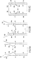
- Figures 5A, 5B, 5C schematic sectional views that illustrate different positions of the endstop device.
- the endstop device may be described as a bi-articulated device because the connecting lug 80 has only two net joints, namely the intermediate transverse fold line 84 and the pre-marked fold line of the corresponding main panel.
- the endstop has been illustrated in an inward longitudinal position.
- the two parts of the connecting lugs 80 are folded over one another in the sense that they form, between them, an angle less than 90 °.
- the tabs 80 are directed longitudinally inward to form a harpoon directed longitudinally inward of the space defined by the envelope formed by the main panels which carry them.
- the intermediate fold line 84 of the connecting lugs forms a projecting edge of the folded connecting lug 80 , this projecting edge being able to bear against a product contained in the packaging to ensure the wedging.
- the end wedging device can be reversibly moved between these two distinct stable longitudinal positions, on either side of an unstable position, illustrated in FIG. Figure 5B
- the main portions 80a of the connecting lugs 80 extend in a transverse plane perpendicular to the longitudinal direction. Due to the absence of a pre-marked transverse fold line between the end panel and the end portion 80b of the corresponding connecting tabs, the bi-articulated end clamping device is resiliently biased toward one or the other of these two longitudinal positions stable under the effect of a restoring force which is due in particular to the elastic deformation of the bending zone at the transition between the end panel and the end portion of the dough link. The same restoring force makes the position illustrated in Figure 5B is an unstable position.
- the closed nature of the contour formed by the end strip 60 contributes to the efforts generated at two legs carried by opposite main panels tend to cancel each other. Moreover, the closed nature of the contour formed by the end strip 60 contributes to the fact that the end panels can not move individually in the transverse direction, and the end strip 60 thus forms a rigid base for taking up the ends. bending stresses generated in the transition zone between the end panel and the end portion 80b of the corresponding connecting tabs, which allows this transition zone to generate a relatively large restoring force.
- the length "la" of the main portion 80a of a connecting lug 80 is less than half the maximum dimension "T" of the inner space of the packaging element in a transverse direction perpendicular to the corresponding main panel.
- This characteristic is especially visible on the Figure 5B where it can be seen that the main portions 80a of the two opposite connecting lugs 80 , that is to say connected to two non-adjacent panels of the envelope, can not come into abutment against each other during the tilting of the end strip 60 between its extended and close positions.
- the maximum dimension 'T' of the inner space of the packaging element, in a transverse direction perpendicular to the corresponding main panel shall in general be equal to the distance between the two longitudinal sides of a main panel adjacent to the panel considered.
- the separating blanks 82 between two adjacent connecting tabs 80 are preferably arranged, as in the example illustrated, in the form of an openwork, that is to say in the form of a cutting that is not a simple cut line.
- the geometry of this openwork is preferably chosen so that, when the main parts 80a of two adjacent connecting lugs, not being linked to the same main panel but being connected to two adjacent main panels, are folded at 90 ° towards the interior space, as illustrated in Figure 5B , The main parts 80a of the adjacent connection tabs do not overlap, particularly in view in the longitudinal direction. This prevents two adjacent tabs abut against each other during the tilting of the end strip between its extended and close positions.
- the connecting tabs each have a main portion 80a whose geometry allows it to be received, folded at 90 ° to the inner space relative to the corresponding main panel, without contacting the adjacent main panels.
- the length of the end portion 80b of a connecting lug as the shortest distance "Ib" between the intermediate fold line 84 and a transverse dividing line between this end part 80b and the corresponding end panel.
- this dividing line is not not marked. It is therefore a theoretical line. It can be defined as the last theoretical line, starting from the corresponding longitudinal end of the packing element, for which there is continuity of material of the end strip over the entire transverse width of the end panel. corresponding. In other words, this theoretical line may be the last theoretical line for which one does not intercept either of the separation blanks 82 on either side of the link tab considered. In the exemplary embodiment illustrated, these two definitions correspond to the virtual transversal line LP1 along which the longitudinal vertices 82b of the cuts 82, on the side of the end panels 61, 62, 63, 64, are aligned.
- the length "la" of the main portion 80a of a connecting lug 80 is less than the length "Ib" of the end portion 80b of the same connecting lug. In this way, it tends to avoid that, during the tilting of the end wedging device between these two stable positions, the bending zone of the end portion of the connecting lug undergoes irreversible damage. Thus, this bending zone remains essentially in its elastic deformation range and thus retains sufficient elasticity to maintain the endstop device in one or other of its stable positions.
- the package 12 comprises only one peripheral casing, formed of the main panels 21, 22, 23, 24, and consists only of a packaging element having a main casing such that defined above, and at least one end stopping device according to the invention comprising an end strip 60 connected to the main panels by connecting lugs 80.
- the end portion 80b of at least two connecting lugs 80 is attached to the corresponding end strip 60 by a bending zone devoid of pre-marked fold transverse line.
- this embodiment comprises two endstop devices, one at each longitudinal end of the package. Such a package is not closed at the longitudinal ends, but the end wedging devices can however lock the product longitudinally inside the package.
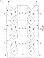
- FIG 8 there is illustrated a blank for the production of a package 12 which comprises only three main panels 21, 22, 23, articulated successively to one another.
- the packaging obtained thanks to such a blank is illustrated on the Figure 9 where we see that its three main panels define a main envelope which defines a triangular closed contour in a transverse plane perpendicular to the longitudinal direction.
- the package has only one peripheral envelope.
- the package 12 comprises at least one end stopping device according to the invention comprising an end strip 60 connected to the main panels by connecting lugs 80.
- the end portion 80b of at least two connecting lugs 80 is attached to the corresponding end strip 60 by a bending zone devoid of pre-marked fold transverse line.
- a wedging end device as described above, of the bi-articulated type, and, at the opposite longitudinal end, a closure device comprising at least one closure flap which would be attached to a transverse edge of a main panel by a transverse fold line.
- a closure device comprising at least one closure flap which would be attached to a transverse edge of a main panel by a transverse fold line.
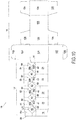
- FIG 10 There is illustrated one embodiment of a single blank for producing packaging comprising an outer shell formed of outer panels 121, 122, 123, 124 and a wedge element 12 formed of main panels 21, 22, 23, 24.
- the number of external panels is equal to the number of main panels.
- the outer panels are not parallel to the main panels.
- the transverse width of the connecting panel 16 is chosen so as to create an angular offset, in a transverse plane perpendicular to the longitudinal direction, between the external panels of the outer envelope and the main panels of the main envelope of the wedging element.
- this embodiment has only one end stopping device according to the invention comprising an end strip 60 connected to the main panels of the wedging element 12 by connecting tabs 80.
- the end portion 80b of at least two connecting lugs 80 is attached to the corresponding end strip 60 by a bending zone devoid of pre-marked folding cross line.
- This end wedging device is arranged at a longitudinal end of the wedging element 12, the other longitudinal end being devoid of it.
- the package comprises an outer envelope formed of outer panels and a wedging element whose main envelope is formed of main panels
- this feature is not mandatory and may be provided packages with more external panels than main panels, or conversely packs with fewer external panels than the main panels of the wedging element.
- the endstop device according to the invention is particularly advantageous for several reasons.
- the end wedging device according to the invention is obtained from the same single blank as the package.
- the realization of the endstop device according to the invention is relatively simple, including at the time of assembly, because it does not require particularly complicated cuts or complex assembly operations.
- all the fold lines are either longitudinal or transverse, without the need for folding around oblique fold lines.
- bistable character is particularly useful at the time of introduction of the product of the package. Before introduction, it is in a stable extended position in which it does not interfere with the introduction of the product into the package.
- This tilting operation can be done by simply pressing on the end strip in the longitudinal direction.
- This operation can be done with an automated push tool, having only one axis of displacement.
- the automated push tool can be the same tool that ensures the introduction of the product into the package.
Landscapes
- Engineering & Computer Science (AREA)
- Mechanical Engineering (AREA)
- Cartons (AREA)
- Packaging Of Annular Or Rod-Shaped Articles, Wearing Apparel, Cassettes, Or The Like (AREA)
Claims (15)
- Verpackungselement (12), hergestellt aus einem einzelnen Rohling, der aus einer Materialbahn vorgeschnitten und gefaltet wird, von der Art, bei der- das Verpackungselement (12) eine Hauptumhüllung aufweist, die mindestens drei Hauptpaneele (21, 22, 23, 24) aufweist, die aufeinanderfolgend um längsgerichtete Faltlinien (31, 32, 33) aneinander angelenkt sind, die sich parallel zueinander in Längsrichtung erstrecken, wobei die Faltlinien Längsseiten der Hauptpaneele definieren, wobei die Umhüllung in sich geschlossen wird, um eine geschlossene Form um einen Innenraum des Verpackungselements in einer zur Längsrichtung senkrechten Querebene zu definieren,- das Verpackungselement zumindest an einem Längsende eine Endverkeilvorrichtung (60, 80) aufweist, umfassend:• einen Endstreifen (60) mit so vielen Endpaneelen (61, 62, 63, 64) wie die Anzahl der Hauptpaneele, die aufeinanderfolgend um Faltlinien, die in Ausrichtung der Faltlinien der Hauptpaneele angeordnet sind, aneinander angelenkt sind, wobei der Endstreifen in sich geschlossen wird, um eine geschlossene Form um einen Innenraum des Verpackungselements in einer zur Längsrichtung senkrechten Querebene zu definieren,• mindestens einen Längsverbindungssteg (80) für mindestens zwei unterschiedliche Hauptpaneele, der dieses Hauptpaneel mit einem entsprechenden Endpaneel verbindet, wobei der Verbindungssteg eines Hauptpaneels von dem (den) Verbindungssteg(en) der anderen Hauptpaneele getrennt ist, wobei die Verbindungsstege (80) quer voneinander durch einen Trennschnitt (82) in der Materialbahn getrennt sind,der Art, dass jeder Verbindungssteg (80) eine querverlaufende Zwischenfaltlinie (84) aufweist, die einen Hauptabschnitt (80a) und einen Endabschnitt (80b) des Verbindungsstegs (80) begrenzt, die jeweils an dem entsprechenden Hauptpaneel und Endpaneel befestigt sind, um eine Annäherung des Endstreifens (60) der Hauptumhüllung zu ermöglichen, indem die beiden Abschnitte (80a, 80b) des Verbindungsstegs um die Zwischenfaltlinie (84) aufeinander gefaltet werden, und der Art, dass der Hauptabschnitt (80a) des Verbindungsstegs über eine vorgeprägte querverlaufende Faltlinie (41, 42, 43, 44) mit dem entsprechenden Hauptpaneel gelenkig verbunden ist,
dadurch gekennzeichnet, dass die Endverkeilvorrichtung eine doppelgelenkige Vorrichtung ist, bei der der Endabschnitt (80b) der mindestens zwei Verbindungsstege (80) an dem entsprechenden Endpaneel (61, 62, 63, 64) über eine Biegezone ohne vorgeprägte querverlaufende Faltlinie befestigt ist. - Verpackungselement nach Anspruch 1, dadurch gekennzeichnet, dass die Länge (la) des Hauptabschnitts (80a) eines Verbindungsstegs (80), definiert als der kürzeste Abstand zwischen der Zwischenfaltlinie (84) und der vorgeprägten querverlaufenden Faltlinie (41, 42, 43, 44) zum Anschluss an die Hauptpaneel (21, 22, 23, 24), kleiner als die Hälfte der maximalen Abmessung des Innenraums (T) des Verpackungselements (12) in Querrichtung senkrecht zum entsprechenden Hauptpaneel ist.
- Verpackungselement nach einem der Ansprüche 1 oder 2, dadurch gekennzeichnet, dass die Länge (la) des Hauptabschnitts (80a) eines Verbindungsstegs, definiert als der kürzeste Abstand zwischen der Zwischenfaltlinie (84) und der vorgeprägten querverlaufenden Faltlinie (41, 42, 43, 44) zum Anschluss an das Hauptpaneel, kleiner ist als die Länge (Ib) des Endabschnitts (80b) des Verbindungsstegs, definiert als der kürzeste Abstand zwischen der Zwischenfaltlinie (84) und einer der letzten theoretischen Linie (LP1) entsprechenden Quertrennlinie, ausgehend vom entsprechenden Längsende des Verpackungselements, für das eine Materialkontinuität des Endstreifens (60) über die gesamte Querbreite des entsprechenden Endpaneels (61, 62, 63, 64) vorhanden ist oder für das keiner der Trennschnitte (82) auf beiden Seiten des Verbindungsstegs (80) aufgefangen wird.
- Verpackungselement nach einem der vorangehenden Ansprüche, dadurch gekennzeichnet, dass zwischen zwei benachbarten Verbindungsstegen (80), die zwei benachbarten Hauptpaneele (41, 42, 43, 44) entsprechen, der Trennschnitt (82) zwischen zwei Verbindungsstegen in Form einer solchen Öffnung angeordnet ist, dass die Hauptabschnitte (80a) der beiden benachbarten Verbindungsstege, wenn sie bezogen auf das entsprechende Hauptpaneel um 90 Grad zum Innenraum gefaltet sind, keine Abdeckung haben.
- Verpackungselement nach einem der vorangehenden Ansprüche, dadurch gekennzeichnet, dass die Verbindungsstege (80) jeweils einen Hauptabschnitt (80a) aufweisen, dessen Geometrie es zulässt, bezogen auf das entsprechende Hauptpaneel (41, 42, 43, 44) um 90 Grad zum Innenraum hin gefaltet aufgenommen zu werden, ohne die benachbarten Hauptpaneele zu berühren.
- Verpackungselement nach einem der vorangehenden Ansprüche, dadurch gekennzeichnet, dass die Endverkeilvorrichtung reversibel zwischen zwei unterschiedlichen stabilen Längslagen auf beiden Seiten einer instabilen Lage verschiebbar ist, in der sich die Hauptabschnitte (80a) der Verbindungsstege (80) in einer zur Längsrichtung senkrechten Querebene erstrecken.
- Verpackungselement nach Anspruch 6, dadurch gekennzeichnet, dass die Endverkeilvorrichtung durch eine Rückstellkraft durch die elastische Verformung der Biegezone der mindestens zwei Verbindungsstege (80) elastisch in ihre zwei unterschiedlichen stabilen Längslagen zurückgezogen wird.
- Verpackungselement nach einem der Ansprüche 6 oder 7, dadurch gekennzeichnet, dass die beiden stabilen Längslagen der Endverkeilvorrichtung eine nach außen ausfahrbare Position aufweisen, in der die Verbindungsstege (80) ausgeklappt sind, und eine nach innen angenäherte Position, in der die beiden Abschnitte (80a, 80b) der Verbindungsstege (80) übereinander gefaltet und in Längsrichtung nach innen gerichtet sind, um einen Widerhaken zu bilden, der in Längsrichtung zum Inneren des durch die Umhüllung begrenzten Raums gerichtet ist.
- Verpackungselement nach einem der vorangehenden Ansprüche, dadurch gekennzeichnet, dass es Teil einer Verpackung (10) ist, die aus einem einzelnen Rohling hergestellt wird, der aus einem einzelnen Kartonbogen vorgeschnitten und gefaltet wird, dessen Gewicht mindestens 180 g/m2 und höchstens 2.000 g/m2 beträgt, wobei die Verpackung (10) zusätzlich zu dem Verpackungselement (12) eine Außenhülle aufweist, die aus Außenpaneelen (121, 122, 123, 124) gebildet ist, die aufeinanderfolgend um längsgerichtete Faltlinien (131, 132, 133) gelenkig miteinander verbunden sind, die sich parallel zueinander in Längsrichtung erstrecken, wobei die Faltlinien Längsseiten der Außenpaneele definieren, wobei die Außenhülle in sich geschlossen wird, um eine geschlossene Form um das Verpackungselement in einer zur Längsrichtung senkrechten Querebene zu definieren.
- Verpackungselement nach Anspruch 9, dadurch gekennzeichnet, dass es mit einem Außenpaneel (121) der Außenhülle über ein Verbindungspaneel (16) verbunden ist, das bezüglich des Außenpaneels entlang einer seiner Längsseiten (130) angelenkt ist und das bezüglich eines Hauptpaneels (24) entlang einer seiner Längsseiten (34) angelenkt ist.
- Verpackungselement nach einem der Ansprüche 9 oder 10, dadurch gekennzeichnet, dass es Stützlaschen (51 - 55) aufweist, die sich in einer oder mehreren Querrichtungen erstrecken und von denen jede in Kontakt mit einer Innenfläche eines Außenpaneels (121, 122, 123, 124) der Außenhülle steht, um mindestens eins der Hauptpaneele (21, 22, 23, 24) des Verpackungselements (12) beabstandet von diesem Außenpaneel der Außenhülle zu halten.
- Vorgeschnittener Rohling für ein Verpackungselement, der in einem Stück aus einer Materialbahn gebildet wird, von der Art, bei der:- mindestens drei Hauptpaneele (21, 22, 23, 24) aufeinanderfolgend um längsgerichtete Faltlinien (31, 32, 33) aneinander angelenkt sind, die sich parallel zueinander in Längsrichtung erstrecken, wobei die Faltlinien Längsseiten der Hauptpaneele definieren,- der Rohling zumindest an einem Längsende eine Endverkeilvorrichtung (60, 80) aufweist, umfassend:• einen Endstreifen (60) mit so vielen Endpaneelen (61, 62, 63, 64) wie die Anzahl der Hauptpaneele, die aufeinanderfolgend um Faltlinien (71, 72, 73) aneinander angeschlossen sind, die in Ausrichtung der Faltlinien der Hauptpaneele angeordnet sind;• mindestens einen Längsverbindungssteg (80) für mindestens zwei unterschiedliche Hauptpaneele, der dieses Hauptpaneel mit einem entsprechenden Endpaneel verbindet, wobei der Verbindungssteg eines Hauptpaneels von dem (den) Verbindungssteg(en) der anderen Hauptpaneele getrennt ist, wobei die Verbindungsstege (80) quer voneinander durch einen Trennschnitt (82) in der Materialbahn getrennt sind;der Art, dass jeder Verbindungssteg (80) eine querverlaufende Zwischenfaltlinie (84) aufweist, die einen Hauptabschnitt (80a) und einen Endabschnitt (80b) des Verbindungsstegs begrenzt, die jeweils an dem entsprechenden Hauptpaneel und Endpaneel befestigt sind, und der Art, dass der Hauptabschnitt des Verbindungsstegs über eine vorgeprägte querverlaufende Faltlinie an dem entsprechenden Hauptpaneel befestigt ist,
dadurch gekennzeichnet, dass der Endabschnitt jedes der mindestens zwei Verbindungsstege an dem entsprechenden Endpaneel über eine Biegezone ohne vorgeprägte querverlaufende Faltlinie befestigt ist. - Vorgeschnittener Rohling nach Anspruch 12, dadurch gekennzeichnet, dass die Länge (la) des Hauptabschnitts (80a) eines Verbindungsstegs (80), definiert als der kürzeste Abstand zwischen der Zwischenfaltlinie (84) und der vorgeprägten querverlaufenden Faltlinie (41, 42, 43, 44) zum Anschluss an das Hauptpaneel (21, 22, 23, 24), kleiner als die Hälfte der Querabmessung eines Hauptpaneels ist, das an das Hauptpaneel angrenzt, an dem der Verbindungssteg befestigt ist, definiert als der Abstand zwischen den beiden Längsseiten (30, 31, 32, 33) des angrenzenden Hauptpaneels.
- Vorgeschnittener Rohling nach einem der Ansprüche 12 oder 13, dadurch gekennzeichnet, dass er an einem Längsende eine Endverkeilvorrichtung (60, 80), die einen Endabschnitt (80b) von mindestens einem an dem entsprechenden Endpaneel (61, 62, 63, 64) über eine Biegezone ohne vorgeprägte querverlaufende Faltlinie befestigten Verbindungssteg (80) aufweist, und am gegenüberliegenden Längsende eine Verschlussvorrichtung mit mindestens einer Verschlussklappe aufweist, die an einer Querkante eines Hauptpaneels über eine querverlaufende Faltlinie befestigt ist.
- Vorgeschnittener Rohling nach einem der Ansprüche 12 bis 14, dadurch gekennzeichnet, dass er weiterhin Außenpaneele (121, 122, 123, 124) aufweist, die aufeinanderfolgend um längsgerichtete Faltlinien (131, 132, 133) gelenkig miteinander verbunden sind, die sich parallel zueinander in Längsrichtung erstrecken, wobei die Faltlinien Längsseiten der Außenpaneele definieren, und dass ein Hauptpaneel (24) mit einem Außenpaneel (121) durch ein Verbindungspaneel (16) verbunden ist, das jeweils über eine Faltlinie (130) mit einer Längsseite eines Außenpaneels und einer Längsseite (34) eines Hauptpaneels verbunden ist.
Applications Claiming Priority (1)
| Application Number | Priority Date | Filing Date | Title |
|---|---|---|---|
| FR1552311A FR3033771B1 (fr) | 2015-03-20 | 2015-03-20 | Element d'emballage et flan pour element d'emballage avec dispositif de calage perfectionne |
Publications (2)
| Publication Number | Publication Date |
|---|---|
| EP3070017A1 EP3070017A1 (de) | 2016-09-21 |
| EP3070017B1 true EP3070017B1 (de) | 2017-12-27 |
Family
ID=53366063
Family Applications (1)
| Application Number | Title | Priority Date | Filing Date |
|---|---|---|---|
| EP16160763.5A Active EP3070017B1 (de) | 2015-03-20 | 2016-03-16 | Verpackungselement und rohling für das verpackungselement mit perfektionierter verkeilvorrichtung |
Country Status (3)
| Country | Link |
|---|---|
| EP (1) | EP3070017B1 (de) |
| ES (1) | ES2663363T3 (de) |
| FR (1) | FR3033771B1 (de) |
Families Citing this family (2)
| Publication number | Priority date | Publication date | Assignee | Title |
|---|---|---|---|---|
| WO2019106188A1 (en) * | 2017-12-01 | 2019-06-06 | Philip Morris Products S.A. | Child-resistant container for consumer articles |
| FR3103797B1 (fr) * | 2019-11-29 | 2021-12-17 | Saica Pack Sl | Emballage de transport avec calage integre a parois multiples et pourvu d'articulations curvilignes et d'articulations en double zigzag. |
Family Cites Families (5)
| Publication number | Priority date | Publication date | Assignee | Title |
|---|---|---|---|---|
| GB365078A (en) * | 1930-10-14 | 1932-01-14 | Britannia Folding Box Company | Improvements in or relating to cartons for packing fragile articles |
| US3134486A (en) * | 1962-08-13 | 1964-05-26 | St Regis Paper Co | Cartons for electrical bulbs and the like |
| US4445613A (en) * | 1982-09-16 | 1984-05-01 | International Paper Company | Protective shipping and display carton |
| JP2000168763A (ja) * | 1998-12-07 | 2000-06-20 | Nippon Shiko Kk | 緩衝機能を有する包装用組立箱 |
| DE202011106417U1 (de) * | 2011-10-07 | 2011-11-21 | Smurfit Kappa Gmbh | Verpackung mit integriertem Schutzpolster |
-
2015
- 2015-03-20 FR FR1552311A patent/FR3033771B1/fr not_active Expired - Fee Related
-
2016
- 2016-03-16 EP EP16160763.5A patent/EP3070017B1/de active Active
- 2016-03-16 ES ES16160763.5T patent/ES2663363T3/es active Active
Non-Patent Citations (1)
| Title |
|---|
| None * |
Also Published As
| Publication number | Publication date |
|---|---|
| FR3033771B1 (fr) | 2017-04-07 |
| ES2663363T3 (es) | 2018-04-12 |
| FR3033771A1 (fr) | 2016-09-23 |
| EP3070017A1 (de) | 2016-09-21 |
Similar Documents
| Publication | Publication Date | Title |
|---|---|---|
| EP3070016B1 (de) | Verpackung und rohling, der ein perfektioniertes verkeilement umfasst | |
| EP0216669B1 (de) | Verbindungssystem für plattenförmige Elemente von halbsteifem Material und Anwendung zum Verriegeln von Kreuzfächern für Flaschenkasten in montierter Lage | |
| CA2228892A1 (fr) | Contenant livre a plat, puis mis en volume en deux phases distinctes, et portant de l'adhesif a effet prolonge | |
| FR2563192A1 (fr) | Emballage comprenant une bande et des volets lateraux | |
| EP3070017B1 (de) | Verpackungselement und rohling für das verpackungselement mit perfektionierter verkeilvorrichtung | |
| EP2241516A1 (de) | Element zum Verkeilen eines in einen Behälter gegebenen Gegenstands | |
| EP3119685B1 (de) | Verpackung für ein produkt und verfahren zur verpackung eines produkts | |
| EP2436607B1 (de) | Zuschnitt zum Herstellen einer Spende-Verpackung, die zwei ineinander greifende Gleitelemente enthält | |
| CH693591A5 (fr) | Boîte pliante pour produits de boulangerie ou de pâtisserie. | |
| EP3144236B1 (de) | Flachvorläufer für eine verpackung, entsprechendes verfahren und entsprechende verpackung | |
| EP3475177B1 (de) | Verpackung mit einem gehäuse und einer schublade, schublade für solch eine verpackung und zuschnitt für solch eine schublade | |
| EP3144238B1 (de) | Verpackung und zuschnitt für eine verpackung mit einer verbesserten öffnungsvorrichtung | |
| EP2687453B1 (de) | Verpackungsetui mit Öffnungskontrollvorrichtung | |
| EP0887275B1 (de) | Verpackung für einen rechteckigen flachen Gegenstand wie eine Fahrzeug-Motorhaube | |
| EP1447335B1 (de) | Originalitätsverschlusssystem für einen Behälter | |
| EP1750239B1 (de) | Hülse zur Etikettierung oder Gruppierung, die insbesondere mindestens einen Körper mit mindestens zwei Doppelhülsen umfasst | |
| EP2829486B1 (de) | Verpackung, die ein Element aus halbsteifem Material und eine Wärmeschrumpffolie umfasst, Zuschnitt und Herstellungsverfahren | |
| EP1803651B1 (de) | Sicherungselement zur Aufhängung eines Gegenstandes und Verpackung mit einem solchen Element | |
| FR2867163A1 (fr) | Dispositif de conditionnement obtenu a partir d'un flan predecoupe | |
| FR3040982A1 (fr) | Emballage et flan avec dispositif de support d'obturateur perfectionne | |
| FR2862283A1 (fr) | Ceinture en matiere pliable, destinee a maintenir un objet, en particulier un manteau, procede de mise en forme de cette ceinture ; et emballage comportant cette ceinture | |
| FR2892708A1 (fr) | Dispositif de protection tubulaire presentant un retrecissement peripherique | |
| FR2774361A1 (fr) | Etui de conditionnement | |
| FR2865716A1 (fr) | Recipient en matiere en feuille pliable. | |
| FR3115271A3 (fr) | « Boîte-enveloppe de forme pyramidale entrouvrant » |
Legal Events
| Date | Code | Title | Description |
|---|---|---|---|
| PUAI | Public reference made under article 153(3) epc to a published international application that has entered the european phase |
Free format text: ORIGINAL CODE: 0009012 |
|
| AK | Designated contracting states |
Kind code of ref document: A1 Designated state(s): AL AT BE BG CH CY CZ DE DK EE ES FI FR GB GR HR HU IE IS IT LI LT LU LV MC MK MT NL NO PL PT RO RS SE SI SK SM TR |
|
| AX | Request for extension of the european patent |
Extension state: BA ME |
|
| 17P | Request for examination filed |
Effective date: 20170227 |
|
| RBV | Designated contracting states (corrected) |
Designated state(s): AL AT BE BG CH CY CZ DE DK EE ES FI FR GB GR HR HU IE IS IT LI LT LU LV MC MK MT NL NO PL PT RO RS SE SI SK SM TR |
|
| 17Q | First examination report despatched |
Effective date: 20170508 |
|
| GRAP | Despatch of communication of intention to grant a patent |
Free format text: ORIGINAL CODE: EPIDOSNIGR1 |
|
| INTG | Intention to grant announced |
Effective date: 20170829 |
|
| GRAA | (expected) grant |
Free format text: ORIGINAL CODE: 0009210 |
|
| GRAS | Grant fee paid |
Free format text: ORIGINAL CODE: EPIDOSNIGR3 |
|
| AK | Designated contracting states |
Kind code of ref document: B1 Designated state(s): AL AT BE BG CH CY CZ DE DK EE ES FI FR GB GR HR HU IE IS IT LI LT LU LV MC MK MT NL NO PL PT RO RS SE SI SK SM TR |
|
| REG | Reference to a national code |
Ref country code: GB Ref legal event code: FG4D Free format text: NOT ENGLISH |
|
| REG | Reference to a national code |
Ref country code: CH Ref legal event code: EP |
|
| REG | Reference to a national code |
Ref country code: AT Ref legal event code: REF Ref document number: 958044 Country of ref document: AT Kind code of ref document: T Effective date: 20180115 |
|
| REG | Reference to a national code |
Ref country code: IE Ref legal event code: FG4D Free format text: LANGUAGE OF EP DOCUMENT: FRENCH |
|
| REG | Reference to a national code |
Ref country code: DE Ref legal event code: R096 Ref document number: 602016001189 Country of ref document: DE |
|
| REG | Reference to a national code |
Ref country code: FR Ref legal event code: PLFP Year of fee payment: 3 |
|
| REG | Reference to a national code |
Ref country code: ES Ref legal event code: FG2A Ref document number: 2663363 Country of ref document: ES Kind code of ref document: T3 Effective date: 20180412 |
|
| PG25 | Lapsed in a contracting state [announced via postgrant information from national office to epo] |
Ref country code: LT Free format text: LAPSE BECAUSE OF FAILURE TO SUBMIT A TRANSLATION OF THE DESCRIPTION OR TO PAY THE FEE WITHIN THE PRESCRIBED TIME-LIMIT Effective date: 20171227 Ref country code: FI Free format text: LAPSE BECAUSE OF FAILURE TO SUBMIT A TRANSLATION OF THE DESCRIPTION OR TO PAY THE FEE WITHIN THE PRESCRIBED TIME-LIMIT Effective date: 20171227 Ref country code: NO Free format text: LAPSE BECAUSE OF FAILURE TO SUBMIT A TRANSLATION OF THE DESCRIPTION OR TO PAY THE FEE WITHIN THE PRESCRIBED TIME-LIMIT Effective date: 20180327 |
|
| REG | Reference to a national code |
Ref country code: NL Ref legal event code: MP Effective date: 20171227 |
|
| REG | Reference to a national code |
Ref country code: LT Ref legal event code: MG4D |
|
| REG | Reference to a national code |
Ref country code: AT Ref legal event code: MK05 Ref document number: 958044 Country of ref document: AT Kind code of ref document: T Effective date: 20171227 |
|
| PG25 | Lapsed in a contracting state [announced via postgrant information from national office to epo] |
Ref country code: LV Free format text: LAPSE BECAUSE OF FAILURE TO SUBMIT A TRANSLATION OF THE DESCRIPTION OR TO PAY THE FEE WITHIN THE PRESCRIBED TIME-LIMIT Effective date: 20171227 Ref country code: RS Free format text: LAPSE BECAUSE OF FAILURE TO SUBMIT A TRANSLATION OF THE DESCRIPTION OR TO PAY THE FEE WITHIN THE PRESCRIBED TIME-LIMIT Effective date: 20171227 Ref country code: HR Free format text: LAPSE BECAUSE OF FAILURE TO SUBMIT A TRANSLATION OF THE DESCRIPTION OR TO PAY THE FEE WITHIN THE PRESCRIBED TIME-LIMIT Effective date: 20171227 Ref country code: GR Free format text: LAPSE BECAUSE OF FAILURE TO SUBMIT A TRANSLATION OF THE DESCRIPTION OR TO PAY THE FEE WITHIN THE PRESCRIBED TIME-LIMIT Effective date: 20180328 Ref country code: BG Free format text: LAPSE BECAUSE OF FAILURE TO SUBMIT A TRANSLATION OF THE DESCRIPTION OR TO PAY THE FEE WITHIN THE PRESCRIBED TIME-LIMIT Effective date: 20180327 |
|
| PG25 | Lapsed in a contracting state [announced via postgrant information from national office to epo] |
Ref country code: NL Free format text: LAPSE BECAUSE OF FAILURE TO SUBMIT A TRANSLATION OF THE DESCRIPTION OR TO PAY THE FEE WITHIN THE PRESCRIBED TIME-LIMIT Effective date: 20171227 |
|
| PG25 | Lapsed in a contracting state [announced via postgrant information from national office to epo] |
Ref country code: CZ Free format text: LAPSE BECAUSE OF FAILURE TO SUBMIT A TRANSLATION OF THE DESCRIPTION OR TO PAY THE FEE WITHIN THE PRESCRIBED TIME-LIMIT Effective date: 20171227 Ref country code: SK Free format text: LAPSE BECAUSE OF FAILURE TO SUBMIT A TRANSLATION OF THE DESCRIPTION OR TO PAY THE FEE WITHIN THE PRESCRIBED TIME-LIMIT Effective date: 20171227 Ref country code: EE Free format text: LAPSE BECAUSE OF FAILURE TO SUBMIT A TRANSLATION OF THE DESCRIPTION OR TO PAY THE FEE WITHIN THE PRESCRIBED TIME-LIMIT Effective date: 20171227 Ref country code: CY Free format text: LAPSE BECAUSE OF FAILURE TO SUBMIT A TRANSLATION OF THE DESCRIPTION OR TO PAY THE FEE WITHIN THE PRESCRIBED TIME-LIMIT Effective date: 20171227 |
|
| PG25 | Lapsed in a contracting state [announced via postgrant information from national office to epo] |
Ref country code: RO Free format text: LAPSE BECAUSE OF FAILURE TO SUBMIT A TRANSLATION OF THE DESCRIPTION OR TO PAY THE FEE WITHIN THE PRESCRIBED TIME-LIMIT Effective date: 20171227 Ref country code: IS Free format text: LAPSE BECAUSE OF FAILURE TO SUBMIT A TRANSLATION OF THE DESCRIPTION OR TO PAY THE FEE WITHIN THE PRESCRIBED TIME-LIMIT Effective date: 20180427 Ref country code: PL Free format text: LAPSE BECAUSE OF FAILURE TO SUBMIT A TRANSLATION OF THE DESCRIPTION OR TO PAY THE FEE WITHIN THE PRESCRIBED TIME-LIMIT Effective date: 20171227 Ref country code: AT Free format text: LAPSE BECAUSE OF FAILURE TO SUBMIT A TRANSLATION OF THE DESCRIPTION OR TO PAY THE FEE WITHIN THE PRESCRIBED TIME-LIMIT Effective date: 20171227 Ref country code: SM Free format text: LAPSE BECAUSE OF FAILURE TO SUBMIT A TRANSLATION OF THE DESCRIPTION OR TO PAY THE FEE WITHIN THE PRESCRIBED TIME-LIMIT Effective date: 20171227 |
|
| PG25 | Lapsed in a contracting state [announced via postgrant information from national office to epo] |
Ref country code: MT Free format text: LAPSE BECAUSE OF FAILURE TO SUBMIT A TRANSLATION OF THE DESCRIPTION OR TO PAY THE FEE WITHIN THE PRESCRIBED TIME-LIMIT Effective date: 20171227 |
|
| REG | Reference to a national code |
Ref country code: DE Ref legal event code: R097 Ref document number: 602016001189 Country of ref document: DE |
|
| PLBE | No opposition filed within time limit |
Free format text: ORIGINAL CODE: 0009261 |
|
| STAA | Information on the status of an ep patent application or granted ep patent |
Free format text: STATUS: NO OPPOSITION FILED WITHIN TIME LIMIT |
|
| PG25 | Lapsed in a contracting state [announced via postgrant information from national office to epo] |
Ref country code: MC Free format text: LAPSE BECAUSE OF FAILURE TO SUBMIT A TRANSLATION OF THE DESCRIPTION OR TO PAY THE FEE WITHIN THE PRESCRIBED TIME-LIMIT Effective date: 20171227 Ref country code: DK Free format text: LAPSE BECAUSE OF FAILURE TO SUBMIT A TRANSLATION OF THE DESCRIPTION OR TO PAY THE FEE WITHIN THE PRESCRIBED TIME-LIMIT Effective date: 20171227 |
|
| 26N | No opposition filed |
Effective date: 20180928 |
|
| REG | Reference to a national code |
Ref country code: IE Ref legal event code: MM4A |
|
| PG25 | Lapsed in a contracting state [announced via postgrant information from national office to epo] |
Ref country code: LU Free format text: LAPSE BECAUSE OF NON-PAYMENT OF DUE FEES Effective date: 20180316 |
|
| PG25 | Lapsed in a contracting state [announced via postgrant information from national office to epo] |
Ref country code: IE Free format text: LAPSE BECAUSE OF NON-PAYMENT OF DUE FEES Effective date: 20180316 |
|
| PG25 | Lapsed in a contracting state [announced via postgrant information from national office to epo] |
Ref country code: SI Free format text: LAPSE BECAUSE OF FAILURE TO SUBMIT A TRANSLATION OF THE DESCRIPTION OR TO PAY THE FEE WITHIN THE PRESCRIBED TIME-LIMIT Effective date: 20171227 |
|
| PG25 | Lapsed in a contracting state [announced via postgrant information from national office to epo] |
Ref country code: TR Free format text: LAPSE BECAUSE OF FAILURE TO SUBMIT A TRANSLATION OF THE DESCRIPTION OR TO PAY THE FEE WITHIN THE PRESCRIBED TIME-LIMIT Effective date: 20171227 |
|
| PG25 | Lapsed in a contracting state [announced via postgrant information from national office to epo] |
Ref country code: PT Free format text: LAPSE BECAUSE OF FAILURE TO SUBMIT A TRANSLATION OF THE DESCRIPTION OR TO PAY THE FEE WITHIN THE PRESCRIBED TIME-LIMIT Effective date: 20171227 |
|
| PG25 | Lapsed in a contracting state [announced via postgrant information from national office to epo] |
Ref country code: HU Free format text: LAPSE BECAUSE OF FAILURE TO SUBMIT A TRANSLATION OF THE DESCRIPTION OR TO PAY THE FEE WITHIN THE PRESCRIBED TIME-LIMIT; INVALID AB INITIO Effective date: 20160316 Ref country code: SE Free format text: LAPSE BECAUSE OF FAILURE TO SUBMIT A TRANSLATION OF THE DESCRIPTION OR TO PAY THE FEE WITHIN THE PRESCRIBED TIME-LIMIT Effective date: 20171227 Ref country code: MK Free format text: LAPSE BECAUSE OF NON-PAYMENT OF DUE FEES Effective date: 20171227 |
|
| PG25 | Lapsed in a contracting state [announced via postgrant information from national office to epo] |
Ref country code: AL Free format text: LAPSE BECAUSE OF FAILURE TO SUBMIT A TRANSLATION OF THE DESCRIPTION OR TO PAY THE FEE WITHIN THE PRESCRIBED TIME-LIMIT Effective date: 20171227 |
|
| PGFP | Annual fee paid to national office [announced via postgrant information from national office to epo] |
Ref country code: ES Payment date: 20250410 Year of fee payment: 10 |
|
| PGFP | Annual fee paid to national office [announced via postgrant information from national office to epo] |
Ref country code: CH Payment date: 20250401 Year of fee payment: 10 |
|
| REG | Reference to a national code |
Ref country code: CH Ref legal event code: U11 Free format text: ST27 STATUS EVENT CODE: U-0-0-U10-U11 (AS PROVIDED BY THE NATIONAL OFFICE) Effective date: 20260401 |
|
| PGFP | Annual fee paid to national office [announced via postgrant information from national office to epo] |
Ref country code: GB Payment date: 20260323 Year of fee payment: 11 |
|
| PGFP | Annual fee paid to national office [announced via postgrant information from national office to epo] |
Ref country code: DE Payment date: 20260313 Year of fee payment: 11 |
|
| PGFP | Annual fee paid to national office [announced via postgrant information from national office to epo] |
Ref country code: BE Payment date: 20260324 Year of fee payment: 11 Ref country code: IT Payment date: 20260310 Year of fee payment: 11 |
|
| PGFP | Annual fee paid to national office [announced via postgrant information from national office to epo] |
Ref country code: FR Payment date: 20260122 Year of fee payment: 11 |