EP3070210B1 - Corps de robinetterie pour une armature sanitaire et procede de fabrication - Google Patents
Corps de robinetterie pour une armature sanitaire et procede de fabrication Download PDFInfo
- Publication number
- EP3070210B1 EP3070210B1 EP16000559.1A EP16000559A EP3070210B1 EP 3070210 B1 EP3070210 B1 EP 3070210B1 EP 16000559 A EP16000559 A EP 16000559A EP 3070210 B1 EP3070210 B1 EP 3070210B1
- Authority
- EP
- European Patent Office
- Prior art keywords
- cover
- receptacle
- base body
- molding compound
- fitting
- Prior art date
- Legal status (The legal status is an assumption and is not a legal conclusion. Google has not performed a legal analysis and makes no representation as to the accuracy of the status listed.)
- Active
Links
Images

Classifications
-
- F—MECHANICAL ENGINEERING; LIGHTING; HEATING; WEAPONS; BLASTING
- F16—ENGINEERING ELEMENTS AND UNITS; GENERAL MEASURES FOR PRODUCING AND MAINTAINING EFFECTIVE FUNCTIONING OF MACHINES OR INSTALLATIONS; THERMAL INSULATION IN GENERAL
- F16K—VALVES; TAPS; COCKS; ACTUATING-FLOATS; DEVICES FOR VENTING OR AERATING
- F16K27/00—Construction of housing; Use of materials therefor
-
- E—FIXED CONSTRUCTIONS
- E03—WATER SUPPLY; SEWERAGE
- E03C—DOMESTIC PLUMBING INSTALLATIONS FOR FRESH WATER OR WASTE WATER; SINKS
- E03C1/00—Domestic plumbing installations for fresh water or waste water; Sinks
- E03C1/02—Plumbing installations for fresh water
- E03C1/04—Water-basin installations specially adapted to wash-basins or baths
- E03C1/0404—Constructional or functional features of the spout
-
- B—PERFORMING OPERATIONS; TRANSPORTING
- B29—WORKING OF PLASTICS; WORKING OF SUBSTANCES IN A PLASTIC STATE IN GENERAL
- B29C—SHAPING OR JOINING OF PLASTICS; SHAPING OF MATERIAL IN A PLASTIC STATE, NOT OTHERWISE PROVIDED FOR; AFTER-TREATMENT OF THE SHAPED PRODUCTS, e.g. REPAIRING
- B29C65/00—Joining or sealing of preformed parts, e.g. welding of plastics materials; Apparatus therefor
- B29C65/70—Joining or sealing of preformed parts, e.g. welding of plastics materials; Apparatus therefor by moulding
-
- B—PERFORMING OPERATIONS; TRANSPORTING
- B29—WORKING OF PLASTICS; WORKING OF SUBSTANCES IN A PLASTIC STATE IN GENERAL
- B29L—INDEXING SCHEME ASSOCIATED WITH SUBCLASS B29C, RELATING TO PARTICULAR ARTICLES
- B29L2031/00—Other particular articles
Definitions
- the present invention relates to a fitting body for a sanitary fitting and a method for producing a fitting body for a sanitary fitting.
- the fitting body is in particular a part or a component of a sanitary fitting.
- Sanitary fittings are, in particular, thermostatic fittings and / or mixer fittings, in particular thermostatic mixer fittings, for bathtubs, wall basins, hand showers or the like.
- the sanitary fittings regularly have a hot water inlet for hot water and a cold water inlet for cold water.
- the sanitary fittings regularly have an outlet opening for mixed water.
- the hot water and cold water can be mixed within the sanitary fitting by means of a thermostatic valve in order to achieve a predeterminable water temperature.
- the water flow or the amount of water can be adjusted by means of a volume regulating valve.
- the valves can be operated by means of separate actuators or by means of a common actuator.
- a base body is formed, for example, from metal, plastic or the like.
- the water channels are introduced into the base body by means of appropriate molding tools during the manufacturing process, in particular during a casting process or injection molding process.
- Another possibility of avoiding undercuts in the demolding direction is to demold the water channels or the waterways in the molding tool in parallel.
- This creates open water channels, based on a separating surface of the base body, which are not undercut in the viewing direction of the separating surface.
- a corresponding cover can be applied to the separating surface.
- Such a cover can be fixed by gluing, screwing, friction welding, vibration welding or the like. This also depends on whether the base body is made of plastic or metal.
- Such a manufacturing process generally takes place in several stages, because the closing of the open channels takes place after the manufacture of the base body and the demolding of the base body.
- Such manufacturing processes are subject to fluctuations, so that the result can only be guaranteed with great effort in a process-reliable and uniform manner in the context of series production.
- Fixing the lid in particular poses some problems in series production. Usually a one-piece cover is used to close all channels. The fixing of the lid is relatively time-consuming with the known methods of gluing, screwing, friction welding and vibration welding. Any several and especially different lids Lid is used, the time required increases accordingly. In addition, there is the problem that the alignment of the cover with respect to the open water channels with the known methods is usually not very exact. In particular, if a one-piece cover is used to close all the water channels of a base body, manufacturing tolerances in the base body and in the cover result in cumulative inaccuracies in the alignment.
- a fitting body for a sanitary fitting is to be specified which is easy to manufacture, requires little installation space and has as few or small sealing points as possible.
- the demoldability should be made easier and undercuts should be avoided in the demolding direction.
- the course of the waterways in the fitting body should be recognizable from the outside.
- a manufacturing method for a fitting body is also to be specified which enables the simplest possible manufacture of a compact fitting body with as few or small sealing points as possible.
- the individual components should be able to be easily demolded and undercuts be avoided.
- the tightness of the waterways in the fitting body should be ensured over a long period of operation.
- a fitting body for a sanitary fitting which has a base body with at least one receptacle, is used for this. At least one laterally open channel is provided in a receptacle base of the at least one receptacle.
- the base body is connected to at least one cover in the region of the at least one receptacle. At least one waterway is formed between the at least one cover and the at least one channel.
- the at least one cover is at least partially arranged in the receptacle. On the outside of the cover, the at least one cover is predominantly covered by a molding compound.
- This type of formation of waterways results in a solid component, in particular a plastic part, with the lowest possible number of external sealing points, which in particular also form a relatively small sealing surface (only) in the adjacent area around the waterways. Due to the covering with the molding compound and in particular the encapsulation with the molding compound, a high level of tightness of the cover and thus also of the fitting body that is as simple as possible to produce is guaranteed.
- a further advantage of the technical solution is that the course of the waterways can be easily recognized from the outside, which can be particularly favored by a molding compound that has a different color than the color of the base body.
- Another advantage of the technical solution is that it is possible to simply close the individual open water channels.
- a solution particularly suitable for series production is thus specified.
- the base body is preferably produced as a cast component and preferably as a one-piece or one-piece cast component.
- the base body can be produced in a casting tool, in particular an injection molding tool and preferably in a plastic injection molding tool.
- the laterally open channels are introduced into the base body, in particular during the casting process or injection molding process, by means of appropriate molding tools.
- the main body has at least one receptacle.
- the receptacle can be formed in the manner of a depression or a recess and / or an elevation or a protrusion (at least partially circumferential to form a channel).
- the base body can be essentially plate-shaped or disk-shaped, the at least one depression / recess or at least one elevation / projection extending inward or outward from the base body.
- the base body can be formed in one piece with the receptacle.
- Disc-shaped or plate-shaped here means that an expansion of the base body in a horizontal direction or width is greater than an expansion of the base body in a vertical direction or height.
- At least one laterally open channel is provided in a receptacle base of the at least one receptacle.
- Lateral (or longitudinally and / or laterally) open here means, in particular, the channel in a direction transverse to its direction of propagation within the base body is openly designed. This serves to avoid undercuts of the channel in the demolding direction of the base body. In other words, this also means that the channels are open laterally in relation to a separation surface or separation plane of the base body and are not undercut in a viewing direction onto the separation plane of the base body.
- a maximum cross-sectional area of the open channel lies in the parting plane of the base body in particular.
- the open channel runs parallel to this parting plane or parting surface and in particular along the parting surface.
- the laterally open channel - and in particular the non-undercut cross-section of the open channel that can be seen in the viewing direction onto the parting plane - is covered or closed by means of the cover when the fitting body is assembled.
- the base body is connected to at least one cover in the region of the at least one receptacle. It is preferred that one (individual) receptacle and, accordingly, also one (individual) cover are provided for each waterway. Such a connection is made by covering with molding compound.
- the base body is preferably connected to the at least one cover in the at least one receptacle. In the case of a finished fitting body, the cover and base body are thus connected to one another.
- At least one waterway is formed between the at least one cover and the at least one channel.
- this also means that the waterway along the flow direction of the water is (only) enclosed by means of the channel and the cover.
- the waterway can have a circular, oval or angular cross section.
- a cross section of the waterway is understood here to be essentially perpendicular to a flow direction or conveying direction of the waterway.
- the cover is not just a flat closure plate here, but preferably has a curved, in particular round or angular, internal shape.
- the at least one cover is at least partially arranged in the receptacle.
- the cover is preferably arranged completely in the receptacle. However, this is not absolutely necessary because at least a part of an outer side of the cover can also protrude or protrude outwardly (longitudinally and / or laterally) beyond the receptacle or the projections.
- the arrangement of the cover in the receptacle has the advantage that the cover can be aligned very easily and precisely with the laterally open channel in the receptacle base of the receptacle.
- the at least one cover can also be produced as a cast component.
- the cover can be produced in a casting tool, in particular an injection molding tool and preferably in a plastic injection molding tool.
- the cover is preferably formed with or from metal or plastic. If the cover is formed with metal, it can be produced, for example, by means of a deep-drawing process, by means of drop forging or the like.
- the at least one cover separates the area of the channels that will later carry water, namely the at least one waterway, from the area in which the molding compound is arranged. Such an area can be, for example, a receptacle that is at least partially filled with molding compound.
- each lid is integrally formed.
- a laterally open channel is closed to the outside by means of several covers.
- each waterway is thus delimited or enclosed to the outside along the flow direction of the water by means of the channel and by means of at least one cover.
- the tightness between the cover and the base body is intended to prevent the molding compound from getting into the waterway during the covering or overmolding.
- the cover rests on a separating surface of the base body, which is produced when the base body is separated or removed from the mold.
- the parting surface lies in a parting plane of the base body.
- the parting surfaces lie along the channels of a plane. It is particularly preferred if all the separating surfaces of a base body lie in a common plane. However, this is not mandatory because the separating surfaces can also lie on several or different planes, in particular planes inclined to one another. It is preferred here that the planes are implemented with slight transitions.
- the laterally open channels are bordered with separating surfaces on both sides along a direction of extent of the channel. It is preferred that these separating surfaces lie in one plane in order to ensure that a cover is in contact with one another as flat and as precisely as possible. This is advantageous if the lid, when it is encapsulated with the molding compound on the outside, has to withstand a high injection pressure in the injection molding tool, in particular a plastic injection molding tool, and should be impervious to the molding compound, in particular a liquid plastic compound.
- the at least one cover is predominantly covered by a molding compound on the outside of the cover, that is to say in particular at least 70% or 80%. In particular, all border areas of the cover and the base body with one another (sealing surfaces) are also included.
- the outside of the lid is preferably (almost or even) completely covered with the molding compound.
- the at least one receptacle above the outside of the lid is at least partially and preferably completely filled with the molding compound.
- the outside of the cover be encapsulated with molding compound.
- the base body and the at least one cover, which has previously been arranged in the at least one receptacle, are introduced into an injection molding tool and the outside of the cover (within the receptacle) is encapsulated using a liquid molding compound.
- Such an overmolding of the outside of the lid can also be understood as an overmolding in particular of an outer surface of the lid.
- the covering with the molding compound can advantageously take place as quickly as possible and in particular in series production.
- it is z. B. also possible that several outer lid sides of a fitting body or several outer lid sides of several fitting bodies are overmolded in one process step, in particular simultaneously.
- an integral connection be established between the molding compound and at least one inner wall of the at least one receptacle.
- This advantageously enables a simple connection between the base body and the cover. Due to the material bond between the molding compound and the inner wall of the receptacle, a particularly high pressure resistance and tightness of the fitting body to the outside is achieved in an advantageous manner.
- At least one collar with a contact surface for the one cover is formed within the at least one receptacle.
- the collar preferably surrounding the channel
- the contact surface can be understood here as a separating surface, as has already been explained above.
- a channel preferably has a contact surface on both sides along its direction of propagation, on which the cover or an underside of the cover can rest as flat and tight as possible. If a channel has round ends, a contact surface can surround the channel.
- the contact surfaces are preferably in one plane.
- At least the base body, the at least one cover or the molding compound is or are formed with a plastic or silicone.
- At least the base body, the at least one cover or the molding compound preferably consists of a plastic or has a plastic.
- this is not mandatory because at least the at least one cover or the base body can be formed with or from metal. That the base body and the (each) lid are formed with or from plastic is particularly advantageous if, for. B. Drinking water should not come into contact with metal.
- the base body, the at least one cover and the molding compound can, however, be formed with or from different plastics.
- the molding compound is formed from or with a particularly strong or dimensionally stable plastic. This leads in an advantageous manner to the fact that that of the fitting body is largely determined by the molding compound. It is further preferred that the molding compound is formed or identified in color in such a way that the waterways can easily be seen from the outside.
- the one cover have local positioning means on the outside for aligning the at least one cover with respect to the at least one channel within the at least one receptacle.
- Latchings and / or snaps for example, can be used as positioning means be provided.
- the positioning means can also be provided, for example, on the outer circumference of the cover, with bulges directed locally outward.
- the local positioning means make it possible in an advantageous manner that the cover can be precisely aligned within the at least one receptacle.
- exact alignment between a cover and a channel to be covered by this cover can be achieved.
- the at least one cover and the base body are preferably provided by means of a casting process in each case, more preferably by means of an injection molding process in each case and very particularly preferably by means of a plastic injection molding process in each case.
- the provision in step a) can take place in a first process step and in particular in a first mold.
- different and in particular separate tool shapes are regularly used for the at least one cover and the base body. If at least one cover and the base body are provided from the same material, they can, however, also be produced in a common tool shape with corresponding recesses.
- step b) at least a part of the at least one cover is arranged in the at least one receptacle, in particular such that the at least one cover with a cover underside is inserted into the at least one receptacle and the cover underside on at least one separating surface or at least one contact surface in the recording comes to the plant.
- At least one collar with a contact surface be formed within the at least one receptacle and the at least one cover being applied to the at least one contact surface in step b).
- step c) the outside of the cover is overmolded with the molding compound.
- the encapsulation in step c) can be carried out in a second process step and in particular in a second mold.
- Fig. 1 shows a fitting body 1 in a sectional view.
- the fitting body 1 has a base body 2 with a receptacle 3.
- the recording 3 is according to the illustration of Fig. 1 edged or surrounded on the left and right by a projection 16 which, if necessary, can also be shaped as a single circumferential projection.
- the base body 2 the projections 16 are formed here as a one-piece plastic injection-molded part.
- the base body 2 is designed essentially in the form of a disk or plate.
- a laterally open channel 6 is formed in a receptacle base 4 of receptacle 3.
- the receptacle 3 and the channel 6 are not undercut in a demolding direction 14. This ensures that the base body can be particularly easily removed from the mold.
- a "separating surface” refers to the separation between the base body 2 and the corresponding mold and in the case shown here, the separating surface is the contact surface or connecting surface or contact surface between the base body 2 and the cover 5.
- a lid outer side 8 of the lid 5 is covered with a molding compound 9.
- the outer side of the cover 8 has been encapsulated with the molding compound 9.
- an integral connection is established between the molding compound 9 and at least one inner wall 10 of the receptacle 3.
- the material connection is present on the left and right on the inner walls 10.
- the base body 2, the cover 5 and the molding compound are each formed from a plastic. It can be seen that the plastic of the molding compound has a different color than the plastic of the base body 2. The course of the waterway 7, which is located below the molding compound 9, can thus be easily recognized from the outside.
- Fig. 1 it is also shown that the receptacle 3 above the lid outer side 8 is completely filled with the molding compound 9, extends approximately up to the level of the receptacle 3 and completely covers the lid 5.
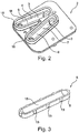
- a perspective view of a base body 2 is shown.
- the base body 2 has two receptacles 3, each with a receptacle base 4.
- a laterally open channel 6 is provided in each receptacle base 4.
- the two laterally open channels 6 can be closed with a cover 5 to form a waterway 7 each.
- the two receptacles 3 are each surrounded or limited by a projection 16 here.
- the two open channels 6 are each surrounded by a collar 11.
- the channels 6 are each formed with round ends and bordered by means of the collar 11.
- FIG. 11 shows a perspective view of a cover 5. It can be seen that the cover 5 has a round-shaped internal cover shape 15. For the exact alignment of the cover 5 of a receptacle 3, the cover 5 has local positioning means 13 on the outside. The positioning means 13 are each formed in the manner of a local external curvature.
- fitting body and a method for producing an armature for a sanitary fitting the fitting body being simple to produce with as few sealing points as possible and the course of the waterways being easy to see from the outside.
- the fitting body is simple to manufacture and, in particular, can be manufactured in series production and requires little installation space.
- the base body of the fitting body can be easily removed from the mold because the open channels of the base body are formed without undercuts in one direction of removal.
Landscapes
- Engineering & Computer Science (AREA)
- General Engineering & Computer Science (AREA)
- Mechanical Engineering (AREA)
- Health & Medical Sciences (AREA)
- Life Sciences & Earth Sciences (AREA)
- Hydrology & Water Resources (AREA)
- Public Health (AREA)
- Water Supply & Treatment (AREA)
- Injection Moulding Of Plastics Or The Like (AREA)
- Moulds For Moulding Plastics Or The Like (AREA)
- Domestic Plumbing Installations (AREA)
- Valve Housings (AREA)
Claims (10)
- Corps de robinetterie (1) pour une armature sanitaire, comportant un corps de base (2) avec au moins un logement (3), sachant que dans une base de logement (4) d'au moins un logement (3) au moins un conduit (6) latéralement ouvert est prévu, sachant que le corps de base (2) est relié dans la zone d'au moins un logement (3) à au moins un couvercle (5), sachant qu'entre au moins un couvercle (5) et au moins un conduit (6) est au moins formée une voie d'eau (7), sachant qu'au moins un couvercle (5) est disposé au moins en partie dans le logement (3) et est couvert sur un côté extérieur de couvercle (8) surtout par une matière moulable (9) de telle manière que le couvercle (5) et le corps de base (2) sont reliés l'un à l'autre, caractérisé en ce que le couvercle (5) est exclusivement relié au corps de base (2) au moyen de la matière moulable (9).
- Corps de robinetterie selon la revendication 1, sachant que le côté extérieur de couvercle (8) est enrobé par injection avec la matière moulable (9).
- Corps de robinetterie selon la revendication 1 ou 2, sachant qu'une liaison par conformité de matière est réalisée entre la matière moulable (9) et au moins une paroi intérieure (10) d'au moins un logement (3).
- Corps de robinetterie selon l'une quelconque des revendications précédentes, sachant qu'à l'intérieur d'au moins un logement (3) au moins un col (11) avec une surface d'appui (12) est formée pour au moins un couvercle (5).
- Corps de robinetterie selon l'une quelconque des revendications précédentes, sachant qu'au moins le corps de base (2), au moins un couvercle (5) ou la matière moulable (9) sont formés d'une matière plastique ou de silicone.
- Corps de robinetterie selon l'une quelconque des revendications précédentes, sachant qu'au moins un couvercle (5) comporte extérieurement des moyens de positionnement (13) locaux pour orienter au moins un couvercle (5) par rapport à au moins un conduit (6) à l'intérieur d'au moins un logement (3).
- Procédé de fabrication d'un corps de robinetterie (1) pour une armature sanitaire, comprenant au moins les étapes suivantes :a) préparation d'au moins un couvercle (5) et d'un corps de base (2) avec au moins un logement (3), sachant que dans une base de logement (4) d'au moins un logement (3), au moins un conduit (6) latéralement ouvert est prévu,b) disposition d'au moins une pièce d'au moins un couvercle (5) dans au moins un logement (3), sachant qu'au moins un couvercle (5) est posé sur le corps de base (2) dans la zone d'au moins un logement (3), sachant qu'au moins une voie d'eau (7) est formée entre au moins un couvercle (5) et au moins un conduit (6),c) couverture d'une partie prédominante d'un côté extérieur de couvercle (8) d'au moins un couvercle (5) avec une matière moulable (9) pour joindre le couvercle (5) et le corps de base (2) l'un à l'autre, caractérisé en ce que le couvercle (5) est exclusivement relié au corps de base (2) au moyen de la matière moulable (9).
- Procédé selon la revendication 7, sachant qu'à l'intérieur d'au moins un logement (3) au moins un col (11) est formé avec une surface d'appui (12) et sachant que dans l'étape b) au moins un couvercle (5) est appuyé sur au moins une surface d'appui (12).
- Procédé selon la revendication 7 ou 8, sachant que dans l'étape c) le côté extérieur de couvercle (8) est enrobé par injection avec la matière moulable (9).
- Procédé selon l'une quelconque des revendications 7 à 9, sachant que dans l'étape c) une liaison par conformité de matière est réalisée entre la matière moulable (9) et au moins une paroi intérieure (10) d'au moins un logement (3).
Applications Claiming Priority (1)
| Application Number | Priority Date | Filing Date | Title |
|---|---|---|---|
| DE102015002894.4A DE102015002894A1 (de) | 2015-03-09 | 2015-03-09 | Armaturenkörper für eine Sanitärarmatur und Herstellungsverfahren |
Publications (2)
| Publication Number | Publication Date |
|---|---|
| EP3070210A1 EP3070210A1 (fr) | 2016-09-21 |
| EP3070210B1 true EP3070210B1 (fr) | 2020-08-26 |
Family
ID=55521335
Family Applications (1)
| Application Number | Title | Priority Date | Filing Date |
|---|---|---|---|
| EP16000559.1A Active EP3070210B1 (fr) | 2015-03-09 | 2016-03-08 | Corps de robinetterie pour une armature sanitaire et procede de fabrication |
Country Status (6)
| Country | Link |
|---|---|
| US (1) | US9933082B2 (fr) |
| EP (1) | EP3070210B1 (fr) |
| CN (1) | CN105952942B (fr) |
| DE (1) | DE102015002894A1 (fr) |
| DK (1) | DK3070210T3 (fr) |
| ES (1) | ES2828280T3 (fr) |
Families Citing this family (4)
| Publication number | Priority date | Publication date | Assignee | Title |
|---|---|---|---|---|
| DE102016007359A1 (de) * | 2016-06-17 | 2017-12-21 | Grohe Ag | Armaturenkörper für eine Sanitärarmatur, aufweisend einen Deckel mit einem Hohlraum |
| US10724215B2 (en) | 2017-09-06 | 2020-07-28 | Kohler Co. | Faucet fixation system |
| JP7222198B2 (ja) * | 2018-08-09 | 2023-02-15 | Toto株式会社 | 湯水混合水栓 |
| DE102020106653A1 (de) * | 2020-03-11 | 2021-09-16 | Grohe Ag | Funktionseinheit für ein Dusch-WC sowie Verfahren zur Herstellung einer solchen Funktionseinheit |
Citations (2)
| Publication number | Priority date | Publication date | Assignee | Title |
|---|---|---|---|---|
| US5579823A (en) * | 1994-04-11 | 1996-12-03 | Moen Incorporated | Method of casting a permanent core plumbing product |
| US20140338777A1 (en) * | 2013-05-17 | 2014-11-20 | Moen Incorporated | Fluid dispensing apparatus and method of manufacture |
Family Cites Families (9)
| Publication number | Priority date | Publication date | Assignee | Title |
|---|---|---|---|---|
| US4649958A (en) * | 1982-06-28 | 1987-03-17 | Masco Corporation Of Indiana | Faucet and spout construction |
| US6817379B2 (en) * | 2001-10-02 | 2004-11-16 | Frank Perla | Water delivery device and method of forming same |
| US20060059686A1 (en) * | 2004-09-21 | 2006-03-23 | Chuan-An Wei | Faucet channel structure and manufacturing method |
| TWM277839U (en) * | 2005-05-12 | 2005-10-11 | Ways Technical Corp | Faucet of composite structure |
| US7484524B1 (en) * | 2006-07-06 | 2009-02-03 | Chang I Sanitary Co., Ltd. | Upright water faucet |
| CN102052481B (zh) * | 2009-10-30 | 2014-03-05 | 浙江三花制冷集团有限公司 | 四通换向阀阀体组件焊接方法 |
| EP2420629B1 (fr) * | 2010-07-28 | 2015-11-04 | Grohe AG | Armature sanitaire |
| CN101947641A (zh) * | 2010-10-28 | 2011-01-19 | 江苏金石铸锻有限公司 | 阀壳的铸造工艺 |
| JP5928905B2 (ja) * | 2013-08-26 | 2016-06-01 | 株式会社鷺宮製作所 | 切換弁 |
-
2015
- 2015-03-09 DE DE102015002894.4A patent/DE102015002894A1/de active Pending
-
2016
- 2016-03-08 EP EP16000559.1A patent/EP3070210B1/fr active Active
- 2016-03-08 DK DK16000559.1T patent/DK3070210T3/da active
- 2016-03-08 ES ES16000559T patent/ES2828280T3/es active Active
- 2016-03-09 US US15/065,402 patent/US9933082B2/en active Active
- 2016-03-09 CN CN201610133610.8A patent/CN105952942B/zh active Active
Patent Citations (2)
| Publication number | Priority date | Publication date | Assignee | Title |
|---|---|---|---|---|
| US5579823A (en) * | 1994-04-11 | 1996-12-03 | Moen Incorporated | Method of casting a permanent core plumbing product |
| US20140338777A1 (en) * | 2013-05-17 | 2014-11-20 | Moen Incorporated | Fluid dispensing apparatus and method of manufacture |
Also Published As
| Publication number | Publication date |
|---|---|
| US9933082B2 (en) | 2018-04-03 |
| CN105952942A (zh) | 2016-09-21 |
| US20160265675A1 (en) | 2016-09-15 |
| ES2828280T3 (es) | 2021-05-25 |
| CN105952942B (zh) | 2019-08-23 |
| DK3070210T3 (da) | 2020-11-16 |
| EP3070210A1 (fr) | 2016-09-21 |
| DE102015002894A1 (de) | 2016-09-15 |
Similar Documents
| Publication | Publication Date | Title |
|---|---|---|
| EP0583599B1 (fr) | Procédé pour la fabrication d'éléments sanitaires et élément obtenu par ce procédé | |
| EP3070209B1 (fr) | Corps de robinetterie pour une armature sanitaire et procede de fabrication | |
| EP3070210B1 (fr) | Corps de robinetterie pour une armature sanitaire et procede de fabrication | |
| DE19744239C2 (de) | Öffnungsfilter und Verfahren zur Herstellung einer Filteranordnung | |
| EP2296776B1 (fr) | Adaptateur de fixation d'un élément filtrant | |
| DE102014004812A1 (de) | Magnetventil, Batterie aus Magnetventilen und Verfahren zur Herstellung eines Magnetventils sowie Werkzeug | |
| EP3730201A1 (fr) | Procédé destiné à fabriquer un élément de filtre pourvu d'une pièce d'étanchéité | |
| EP3012084A1 (fr) | Raccord | |
| EP1355057A2 (fr) | Dispositif pour la recirculation des gaz d'échappement d'un moteur à combustion interne | |
| WO2002010626A1 (fr) | Piston de soupape pour soupapes a voies multiples | |
| DE2704026C2 (de) | Spritzgießvorrichtung zum Aufbringen einer Kunststoff-Beschichtung auf Oberflächen eines Ventilkörpers | |
| DE102009003198A1 (de) | Verfahren zur Herstellung eines Anschlussteils eines Heizkörpers sowie Anschlussteil eines Heizkörpers | |
| DE102009048135B4 (de) | Gehäuse für eine elektronische Steuereinheit | |
| DE29521334U1 (de) | Maschinenbauteil mit einer Dichtung | |
| DE102011050973B4 (de) | Vakuumventil, Werkzeug mit einem derartigen Vakuumventil und Verfahren für ein derartiges Werkzeug | |
| DE202009008183U1 (de) | Ventil | |
| DE202012100983U1 (de) | Formwerkzeug für Becherdeckel und dieser Becherdeckel | |
| DE102005016777B4 (de) | Verfahren zur Herstellung eines Kunststoffgehäuses aus zwei Gehäuseteilen , insbesondere für eine Saugstrahlpumpe | |
| EP1741531A1 (fr) | Moule pour la fabrication d'un écran thérmique en céramique | |
| DE102015221377A1 (de) | Kunststoffbehälter mit topfartigem Einbaukörper | |
| WO2018108692A1 (fr) | Moule de formage destiné au formage d'une section de moule sur une pièce à usiner | |
| DE102023133789A1 (de) | Auslaufstoppventil, insbesondere für eine Steckverbindung | |
| DE102015014716A1 (de) | Verfahren zur Herstellung eines Endlosbandes, Gussform hierfür und Endlosband | |
| EP4268993A1 (fr) | Dispositif d'insertion, appareil et procédé de fabrication de pièce moulée | |
| DE4201332A1 (de) | Verfahren und vorrichtung zur herstellung von fassdeckeln sowie fassdeckel |
Legal Events
| Date | Code | Title | Description |
|---|---|---|---|
| PUAI | Public reference made under article 153(3) epc to a published international application that has entered the european phase |
Free format text: ORIGINAL CODE: 0009012 |
|
| AK | Designated contracting states |
Kind code of ref document: A1 Designated state(s): AL AT BE BG CH CY CZ DE DK EE ES FI FR GB GR HR HU IE IS IT LI LT LU LV MC MK MT NL NO PL PT RO RS SE SI SK SM TR |
|
| AX | Request for extension of the european patent |
Extension state: BA ME |
|
| STAA | Information on the status of an ep patent application or granted ep patent |
Free format text: STATUS: REQUEST FOR EXAMINATION WAS MADE |
|
| 17P | Request for examination filed |
Effective date: 20170321 |
|
| RBV | Designated contracting states (corrected) |
Designated state(s): AL AT BE BG CH CY CZ DE DK EE ES FI FR GB GR HR HU IE IS IT LI LT LU LV MC MK MT NL NO PL PT RO RS SE SI SK SM TR |
|
| STAA | Information on the status of an ep patent application or granted ep patent |
Free format text: STATUS: EXAMINATION IS IN PROGRESS |
|
| 17Q | First examination report despatched |
Effective date: 20190611 |
|
| GRAP | Despatch of communication of intention to grant a patent |
Free format text: ORIGINAL CODE: EPIDOSNIGR1 |
|
| STAA | Information on the status of an ep patent application or granted ep patent |
Free format text: STATUS: GRANT OF PATENT IS INTENDED |
|
| INTG | Intention to grant announced |
Effective date: 20200602 |
|
| GRAS | Grant fee paid |
Free format text: ORIGINAL CODE: EPIDOSNIGR3 |
|
| GRAA | (expected) grant |
Free format text: ORIGINAL CODE: 0009210 |
|
| STAA | Information on the status of an ep patent application or granted ep patent |
Free format text: STATUS: THE PATENT HAS BEEN GRANTED |
|
| AK | Designated contracting states |
Kind code of ref document: B1 Designated state(s): AL AT BE BG CH CY CZ DE DK EE ES FI FR GB GR HR HU IE IS IT LI LT LU LV MC MK MT NL NO PL PT RO RS SE SI SK SM TR |
|
| REG | Reference to a national code |
Ref country code: GB Ref legal event code: FG4D Free format text: NOT ENGLISH |
|
| REG | Reference to a national code |
Ref country code: CH Ref legal event code: EP |
|
| REG | Reference to a national code |
Ref country code: AT Ref legal event code: REF Ref document number: 1306487 Country of ref document: AT Kind code of ref document: T Effective date: 20200915 |
|
| REG | Reference to a national code |
Ref country code: IE Ref legal event code: FG4D Free format text: LANGUAGE OF EP DOCUMENT: GERMAN |
|
| REG | Reference to a national code |
Ref country code: DE Ref legal event code: R096 Ref document number: 502016010918 Country of ref document: DE |
|
| REG | Reference to a national code |
Ref country code: DK Ref legal event code: T3 Effective date: 20201113 |
|
| REG | Reference to a national code |
Ref country code: FI Ref legal event code: FGE |
|
| REG | Reference to a national code |
Ref country code: SE Ref legal event code: TRGR |
|
| REG | Reference to a national code |
Ref country code: LT Ref legal event code: MG4D |
|
| PG25 | Lapsed in a contracting state [announced via postgrant information from national office to epo] |
Ref country code: PT Free format text: LAPSE BECAUSE OF FAILURE TO SUBMIT A TRANSLATION OF THE DESCRIPTION OR TO PAY THE FEE WITHIN THE PRESCRIBED TIME-LIMIT Effective date: 20201228 Ref country code: GR Free format text: LAPSE BECAUSE OF FAILURE TO SUBMIT A TRANSLATION OF THE DESCRIPTION OR TO PAY THE FEE WITHIN THE PRESCRIBED TIME-LIMIT Effective date: 20201127 Ref country code: NO Free format text: LAPSE BECAUSE OF FAILURE TO SUBMIT A TRANSLATION OF THE DESCRIPTION OR TO PAY THE FEE WITHIN THE PRESCRIBED TIME-LIMIT Effective date: 20201126 Ref country code: HR Free format text: LAPSE BECAUSE OF FAILURE TO SUBMIT A TRANSLATION OF THE DESCRIPTION OR TO PAY THE FEE WITHIN THE PRESCRIBED TIME-LIMIT Effective date: 20200826 Ref country code: BG Free format text: LAPSE BECAUSE OF FAILURE TO SUBMIT A TRANSLATION OF THE DESCRIPTION OR TO PAY THE FEE WITHIN THE PRESCRIBED TIME-LIMIT Effective date: 20201126 Ref country code: LT Free format text: LAPSE BECAUSE OF FAILURE TO SUBMIT A TRANSLATION OF THE DESCRIPTION OR TO PAY THE FEE WITHIN THE PRESCRIBED TIME-LIMIT Effective date: 20200826 |
|
| REG | Reference to a national code |
Ref country code: NL Ref legal event code: MP Effective date: 20200826 |
|
| PG25 | Lapsed in a contracting state [announced via postgrant information from national office to epo] |
Ref country code: PL Free format text: LAPSE BECAUSE OF FAILURE TO SUBMIT A TRANSLATION OF THE DESCRIPTION OR TO PAY THE FEE WITHIN THE PRESCRIBED TIME-LIMIT Effective date: 20200826 Ref country code: RS Free format text: LAPSE BECAUSE OF FAILURE TO SUBMIT A TRANSLATION OF THE DESCRIPTION OR TO PAY THE FEE WITHIN THE PRESCRIBED TIME-LIMIT Effective date: 20200826 Ref country code: LV Free format text: LAPSE BECAUSE OF FAILURE TO SUBMIT A TRANSLATION OF THE DESCRIPTION OR TO PAY THE FEE WITHIN THE PRESCRIBED TIME-LIMIT Effective date: 20200826 Ref country code: NL Free format text: LAPSE BECAUSE OF FAILURE TO SUBMIT A TRANSLATION OF THE DESCRIPTION OR TO PAY THE FEE WITHIN THE PRESCRIBED TIME-LIMIT Effective date: 20200826 Ref country code: IS Free format text: LAPSE BECAUSE OF FAILURE TO SUBMIT A TRANSLATION OF THE DESCRIPTION OR TO PAY THE FEE WITHIN THE PRESCRIBED TIME-LIMIT Effective date: 20201226 |
|
| PG25 | Lapsed in a contracting state [announced via postgrant information from national office to epo] |
Ref country code: CZ Free format text: LAPSE BECAUSE OF FAILURE TO SUBMIT A TRANSLATION OF THE DESCRIPTION OR TO PAY THE FEE WITHIN THE PRESCRIBED TIME-LIMIT Effective date: 20200826 Ref country code: EE Free format text: LAPSE BECAUSE OF FAILURE TO SUBMIT A TRANSLATION OF THE DESCRIPTION OR TO PAY THE FEE WITHIN THE PRESCRIBED TIME-LIMIT Effective date: 20200826 Ref country code: RO Free format text: LAPSE BECAUSE OF FAILURE TO SUBMIT A TRANSLATION OF THE DESCRIPTION OR TO PAY THE FEE WITHIN THE PRESCRIBED TIME-LIMIT Effective date: 20200826 Ref country code: SM Free format text: LAPSE BECAUSE OF FAILURE TO SUBMIT A TRANSLATION OF THE DESCRIPTION OR TO PAY THE FEE WITHIN THE PRESCRIBED TIME-LIMIT Effective date: 20200826 |
|
| REG | Reference to a national code |
Ref country code: ES Ref legal event code: FG2A Ref document number: 2828280 Country of ref document: ES Kind code of ref document: T3 Effective date: 20210525 |
|
| RAP4 | Party data changed (patent owner data changed or rights of a patent transferred) |
Owner name: GROHE AG |
|
| REG | Reference to a national code |
Ref country code: DE Ref legal event code: R097 Ref document number: 502016010918 Country of ref document: DE |
|
| PG25 | Lapsed in a contracting state [announced via postgrant information from national office to epo] |
Ref country code: AL Free format text: LAPSE BECAUSE OF FAILURE TO SUBMIT A TRANSLATION OF THE DESCRIPTION OR TO PAY THE FEE WITHIN THE PRESCRIBED TIME-LIMIT Effective date: 20200826 |
|
| PG25 | Lapsed in a contracting state [announced via postgrant information from national office to epo] |
Ref country code: SK Free format text: LAPSE BECAUSE OF FAILURE TO SUBMIT A TRANSLATION OF THE DESCRIPTION OR TO PAY THE FEE WITHIN THE PRESCRIBED TIME-LIMIT Effective date: 20200826 |
|
| PLBE | No opposition filed within time limit |
Free format text: ORIGINAL CODE: 0009261 |
|
| STAA | Information on the status of an ep patent application or granted ep patent |
Free format text: STATUS: NO OPPOSITION FILED WITHIN TIME LIMIT |
|
| 26N | No opposition filed |
Effective date: 20210527 |
|
| PG25 | Lapsed in a contracting state [announced via postgrant information from national office to epo] |
Ref country code: SI Free format text: LAPSE BECAUSE OF FAILURE TO SUBMIT A TRANSLATION OF THE DESCRIPTION OR TO PAY THE FEE WITHIN THE PRESCRIBED TIME-LIMIT Effective date: 20200826 |
|
| PG25 | Lapsed in a contracting state [announced via postgrant information from national office to epo] |
Ref country code: MC Free format text: LAPSE BECAUSE OF FAILURE TO SUBMIT A TRANSLATION OF THE DESCRIPTION OR TO PAY THE FEE WITHIN THE PRESCRIBED TIME-LIMIT Effective date: 20200826 |
|
| REG | Reference to a national code |
Ref country code: BE Ref legal event code: MM Effective date: 20210331 |
|
| PG25 | Lapsed in a contracting state [announced via postgrant information from national office to epo] |
Ref country code: IE Free format text: LAPSE BECAUSE OF NON-PAYMENT OF DUE FEES Effective date: 20210308 Ref country code: LU Free format text: LAPSE BECAUSE OF NON-PAYMENT OF DUE FEES Effective date: 20210308 |
|
| REG | Reference to a national code |
Ref country code: AT Ref legal event code: MM01 Ref document number: 1306487 Country of ref document: AT Kind code of ref document: T Effective date: 20210308 |
|
| PG25 | Lapsed in a contracting state [announced via postgrant information from national office to epo] |
Ref country code: BE Free format text: LAPSE BECAUSE OF NON-PAYMENT OF DUE FEES Effective date: 20210331 |
|
| PG25 | Lapsed in a contracting state [announced via postgrant information from national office to epo] |
Ref country code: AT Free format text: LAPSE BECAUSE OF NON-PAYMENT OF DUE FEES Effective date: 20210308 |
|
| PG25 | Lapsed in a contracting state [announced via postgrant information from national office to epo] |
Ref country code: HU Free format text: LAPSE BECAUSE OF FAILURE TO SUBMIT A TRANSLATION OF THE DESCRIPTION OR TO PAY THE FEE WITHIN THE PRESCRIBED TIME-LIMIT; INVALID AB INITIO Effective date: 20160308 |
|
| PG25 | Lapsed in a contracting state [announced via postgrant information from national office to epo] |
Ref country code: CY Free format text: LAPSE BECAUSE OF FAILURE TO SUBMIT A TRANSLATION OF THE DESCRIPTION OR TO PAY THE FEE WITHIN THE PRESCRIBED TIME-LIMIT Effective date: 20200826 |
|
| P01 | Opt-out of the competence of the unified patent court (upc) registered |
Effective date: 20230526 |
|
| PG25 | Lapsed in a contracting state [announced via postgrant information from national office to epo] |
Ref country code: MK Free format text: LAPSE BECAUSE OF FAILURE TO SUBMIT A TRANSLATION OF THE DESCRIPTION OR TO PAY THE FEE WITHIN THE PRESCRIBED TIME-LIMIT Effective date: 20200826 |
|
| PG25 | Lapsed in a contracting state [announced via postgrant information from national office to epo] |
Ref country code: MT Free format text: LAPSE BECAUSE OF FAILURE TO SUBMIT A TRANSLATION OF THE DESCRIPTION OR TO PAY THE FEE WITHIN THE PRESCRIBED TIME-LIMIT Effective date: 20200826 |
|
| PGFP | Annual fee paid to national office [announced via postgrant information from national office to epo] |
Ref country code: ES Payment date: 20250402 Year of fee payment: 10 |
|
| PGFP | Annual fee paid to national office [announced via postgrant information from national office to epo] |
Ref country code: CH Payment date: 20250401 Year of fee payment: 10 |
|
| PG25 | Lapsed in a contracting state [announced via postgrant information from national office to epo] |
Ref country code: TR Free format text: LAPSE BECAUSE OF FAILURE TO SUBMIT A TRANSLATION OF THE DESCRIPTION OR TO PAY THE FEE WITHIN THE PRESCRIBED TIME-LIMIT Effective date: 20200826 |
|
| REG | Reference to a national code |
Ref country code: CH Ref legal event code: U11 Free format text: ST27 STATUS EVENT CODE: U-0-0-U10-U11 (AS PROVIDED BY THE NATIONAL OFFICE) Effective date: 20260401 |
|
| PGFP | Annual fee paid to national office [announced via postgrant information from national office to epo] |
Ref country code: SE Payment date: 20260324 Year of fee payment: 11 |
|
| PGFP | Annual fee paid to national office [announced via postgrant information from national office to epo] |
Ref country code: GB Payment date: 20260306 Year of fee payment: 11 |
|
| PGFP | Annual fee paid to national office [announced via postgrant information from national office to epo] |
Ref country code: DE Payment date: 20260317 Year of fee payment: 11 Ref country code: DK Payment date: 20260305 Year of fee payment: 11 |
|
| PGFP | Annual fee paid to national office [announced via postgrant information from national office to epo] |
Ref country code: FI Payment date: 20260324 Year of fee payment: 11 Ref country code: IT Payment date: 20260310 Year of fee payment: 11 |
|
| PGFP | Annual fee paid to national office [announced via postgrant information from national office to epo] |
Ref country code: FR Payment date: 20260306 Year of fee payment: 11 |