EP3071362B1 - Tête de découpe laser avec une unité de refoidissement fixée à la tête ; machine-outil de découpe et/ou poinconnage avec une telle tête de découpe laser - Google Patents
Tête de découpe laser avec une unité de refoidissement fixée à la tête ; machine-outil de découpe et/ou poinconnage avec une telle tête de découpe laser Download PDFInfo
- Publication number
- EP3071362B1 EP3071362B1 EP14809305.7A EP14809305A EP3071362B1 EP 3071362 B1 EP3071362 B1 EP 3071362B1 EP 14809305 A EP14809305 A EP 14809305A EP 3071362 B1 EP3071362 B1 EP 3071362B1
- Authority
- EP
- European Patent Office
- Prior art keywords
- laser cutting
- cutting head
- focusing
- laser
- cooling unit
- Prior art date
- Legal status (The legal status is an assumption and is not a legal conclusion. Google has not performed a legal analysis and makes no representation as to the accuracy of the status listed.)
- Active
Links
Images




Classifications
-
- B—PERFORMING OPERATIONS; TRANSPORTING
- B23—MACHINE TOOLS; METAL-WORKING NOT OTHERWISE PROVIDED FOR
- B23K—SOLDERING OR UNSOLDERING; WELDING; CLADDING OR PLATING BY SOLDERING OR WELDING; CUTTING BY APPLYING HEAT LOCALLY, e.g. FLAME CUTTING; WORKING BY LASER BEAM
- B23K26/00—Working by laser beam, e.g. welding, cutting or boring
- B23K26/36—Removing material
- B23K26/38—Removing material by boring or cutting
-
- B—PERFORMING OPERATIONS; TRANSPORTING
- B23—MACHINE TOOLS; METAL-WORKING NOT OTHERWISE PROVIDED FOR
- B23K—SOLDERING OR UNSOLDERING; WELDING; CLADDING OR PLATING BY SOLDERING OR WELDING; CUTTING BY APPLYING HEAT LOCALLY, e.g. FLAME CUTTING; WORKING BY LASER BEAM
- B23K26/00—Working by laser beam, e.g. welding, cutting or boring
- B23K26/02—Positioning or observing the workpiece, e.g. with respect to the point of impact; Aligning, aiming or focusing the laser beam
- B23K26/04—Automatically aligning, aiming or focusing the laser beam, e.g. using the back-scattered light
- B23K26/046—Automatically focusing the laser beam
-
- B—PERFORMING OPERATIONS; TRANSPORTING
- B23—MACHINE TOOLS; METAL-WORKING NOT OTHERWISE PROVIDED FOR
- B23K—SOLDERING OR UNSOLDERING; WELDING; CLADDING OR PLATING BY SOLDERING OR WELDING; CUTTING BY APPLYING HEAT LOCALLY, e.g. FLAME CUTTING; WORKING BY LASER BEAM
- B23K26/00—Working by laser beam, e.g. welding, cutting or boring
- B23K26/02—Positioning or observing the workpiece, e.g. with respect to the point of impact; Aligning, aiming or focusing the laser beam
- B23K26/06—Shaping the laser beam, e.g. by masks or multi-focusing
- B23K26/064—Shaping the laser beam, e.g. by masks or multi-focusing by means of optical elements, e.g. lenses, mirrors or prisms
- B23K26/0648—Shaping the laser beam, e.g. by masks or multi-focusing by means of optical elements, e.g. lenses, mirrors or prisms comprising lenses
-
- B—PERFORMING OPERATIONS; TRANSPORTING
- B23—MACHINE TOOLS; METAL-WORKING NOT OTHERWISE PROVIDED FOR
- B23K—SOLDERING OR UNSOLDERING; WELDING; CLADDING OR PLATING BY SOLDERING OR WELDING; CUTTING BY APPLYING HEAT LOCALLY, e.g. FLAME CUTTING; WORKING BY LASER BEAM
- B23K26/00—Working by laser beam, e.g. welding, cutting or boring
- B23K26/08—Devices involving relative movement between laser beam and workpiece
-
- B—PERFORMING OPERATIONS; TRANSPORTING
- B23—MACHINE TOOLS; METAL-WORKING NOT OTHERWISE PROVIDED FOR
- B23K—SOLDERING OR UNSOLDERING; WELDING; CLADDING OR PLATING BY SOLDERING OR WELDING; CUTTING BY APPLYING HEAT LOCALLY, e.g. FLAME CUTTING; WORKING BY LASER BEAM
- B23K26/00—Working by laser beam, e.g. welding, cutting or boring
- B23K26/14—Working by laser beam, e.g. welding, cutting or boring using a fluid stream, e.g. a jet of gas, in conjunction with the laser beam; Nozzles therefor
- B23K26/1462—Nozzles; Features related to nozzles
-
- B—PERFORMING OPERATIONS; TRANSPORTING
- B23—MACHINE TOOLS; METAL-WORKING NOT OTHERWISE PROVIDED FOR
- B23K—SOLDERING OR UNSOLDERING; WELDING; CLADDING OR PLATING BY SOLDERING OR WELDING; CUTTING BY APPLYING HEAT LOCALLY, e.g. FLAME CUTTING; WORKING BY LASER BEAM
- B23K26/00—Working by laser beam, e.g. welding, cutting or boring
- B23K26/70—Auxiliary operations or equipment
-
- B—PERFORMING OPERATIONS; TRANSPORTING
- B23—MACHINE TOOLS; METAL-WORKING NOT OTHERWISE PROVIDED FOR
- B23K—SOLDERING OR UNSOLDERING; WELDING; CLADDING OR PLATING BY SOLDERING OR WELDING; CUTTING BY APPLYING HEAT LOCALLY, e.g. FLAME CUTTING; WORKING BY LASER BEAM
- B23K26/00—Working by laser beam, e.g. welding, cutting or boring
- B23K26/70—Auxiliary operations or equipment
- B23K26/702—Auxiliary equipment
- B23K26/703—Cooling arrangements
-
- B—PERFORMING OPERATIONS; TRANSPORTING
- B23—MACHINE TOOLS; METAL-WORKING NOT OTHERWISE PROVIDED FOR
- B23K—SOLDERING OR UNSOLDERING; WELDING; CLADDING OR PLATING BY SOLDERING OR WELDING; CUTTING BY APPLYING HEAT LOCALLY, e.g. FLAME CUTTING; WORKING BY LASER BEAM
- B23K26/00—Working by laser beam, e.g. welding, cutting or boring
- B23K26/70—Auxiliary operations or equipment
- B23K26/702—Auxiliary equipment
- B23K26/707—Auxiliary equipment for monitoring laser beam transmission optics
-
- G—PHYSICS
- G03—PHOTOGRAPHY; CINEMATOGRAPHY; ANALOGOUS TECHNIQUES USING WAVES OTHER THAN OPTICAL WAVES; ELECTROGRAPHY; HOLOGRAPHY
- G03B—APPARATUS OR ARRANGEMENTS FOR TAKING PHOTOGRAPHS OR FOR PROJECTING OR VIEWING THEM; APPARATUS OR ARRANGEMENTS EMPLOYING ANALOGOUS TECHNIQUES USING WAVES OTHER THAN OPTICAL WAVES; ACCESSORIES THEREFOR
- G03B30/00—Camera modules comprising integrated lens units and imaging units, specially adapted for being embedded in other devices, e.g. mobile phones or vehicles
Definitions
- the present invention relates to laser cutting devices for cutting machine tools and in particular relates to a laser cutting head according to the preamble of claim 1 (see, for example, WO2012/157355 A1 ), to be used in a fiber optic laser cutting system in a cutting/punching machine tool for sheet metal.
- a laser device emits a coherent, monochrome ray of light, concentrated in a rectilinear beam having extremely high luminosity (brilliance), by means of a stimulated emission process.
- the possibility of concentrating a large amount of energy in a very small point enables laser devices to cut, engrave and weld metals.
- the cutting of metallic material typically occurs by vaporization and, particularly, by fusion. In this last case the laser beam melts a small point of the metal and the molten metal (dross) is removed by a blast or jet of gas.
- laser source can be used to generate a light beam suitable for cutting metal.
- gas dioxide, carbon monoxide, CO2
- solid-state lasers are used.
- the laser beam is focused on the workpieces by a laser cutting head, or focusing head, that is connected to the emission apparatus by an optical chain (in CO2 lasers) or a transmission fiber (optical fiber, for example in YAG diode lasers). Because of its reduced dimensions and weight, the laser cutting head can, in fact, be moved with precision and speed by the machine tool in order to cut the workpiece.
- the latter typically comprises an optical collimator which converges the light beam leaving the optical fiber on a focusing unit capable of focusing the collimated laser beam on the workpiece to be cut.
- the focused laser beam leaves the focusing head through a cutting nozzle which concentrates the blast or jet of gas used to remove the dross generated by the fusion of the metal and limits the probability of the dross reaching the focusing unit.
- the focusing unit allows concentrating the laser beam, i.e. positioning the focal point or focus thereof on a given point on the surface of the workpiece to cut or immediately underneath this surface.
- the focusing unit typically comprises a focusing lens mounted on a lens-holder slide or carriage that is movable along an adjustment direction that is parallel to the direction of the laser beam so that the latter can be focused. More precisely, the lens-holder slide is moved by a respective actuator which is controlled according to a distance between the cutting head and the surface of the workpiece, said distance being measured by a suitable sensor that is mounted on the cutting head.
- the surface of the workpiece (a large sheet of metal, for example) is, in fact, generally irregular, not flat, curved.
- the focusing lens and the relative lens-holder slide are housed inside a hermetically closed container or casing so as to prevent the entry of contaminating and extraneous elements that could dirty the lens and thus alters the optical characteristics thereof.
- Cooling systems are provided to cool the cutting head and, in particular, the focusing lens.
- thermo focus shift makes impossible for the cutting system to focus the laser beam in the desired optimal point on the surface of the workpiece, and determines a consequent deterioration in the cutting characteristics to the point of it being impossible to make the cut at all.
- the temperature increase may also damage the protective layer that is generally provided on the surfaces of the lenses and thus causes a further variation of the optical characteristics of the lenses.
- External cooling of the casing containing the focusing unit is not, in fact, sufficient to guarantee an adequate cooling of the focusing lens.
- cooling systems using a gas flow have the drawback of requiring the use of expensive gases that are devoid of contaminating elements. Contaminating or extraneous particles or elements contained in the gas may deposit on the focusing lens, causing not only a variation of the refraction index of the optics, but also an absorption of the energy of the laser beam and hence a reduction in the power available for cutting.
- JP 2012091191 discloses a laser machining apparatus that includes a laser emitting unit provided with laser generating means for generating a laser beam, a laser head provided with galvano scanners for emitting the laser beam outputted from the laser emitting unit to a workpiece, and an optical fiber cable for transmitting the laser beam from the laser emitting unit to the laser head.
- the optical fiber cable is provided with a head connector attached detachably on the laser head.
- the head connector is provided with a beam expander that includes a diffusion lens for diffusing the laser beam emitted from the optical fiber cable and a convergent lens for making the laser beam emitted from the diffusion lens converge as a parallel beam.
- US 20080030823 discloses a method and device for focusing a laser beam outputted from a laser oscillator through a lens and irradiating an object.
- the device comprises mirrors for reflecting the laser beam outputted from the laser oscillator and a condenser lens for focusing the laser beam and irradiating the object. Because a focal distance of the condenser lens can change due to a change in temperature, when irradiation of the laser beam is restarted after the irradiation has stopped, the lens tube containing the condenser lens is heated or cooled by a temperature control device provided with a Peltier device.
- US 6198579 discloses an objective with optical elements, particularly lens, for a projection exposure device used in semiconductor microlithography.
- the objective is provided with a cooling device for the correction of image errors due to the heating effects in the optical elements, in particular due to non-rotationally-symmetrical temperature distributions in the optical elements.
- the cooling device comprises several Peltier elements that are arranged on at least one of the optical elements, distributed over its periphery, and are differently driven electrically in order to act on the temperature distribution in the optical element.
- a further object is to obtain a laser cutting head provided with a cooling system having a simple and economic construction and effective and reliable operation.
- Still another object is to provide a laser cutting head allowing maintaining the focus of the laser beam in a fixed position, even after prolonged and intensive use.
- a laser cutting head is provided as defined in claim 1.
- Other preferred embodiments of this laser cutting head are defined in claims 2 to 12.
- a laser cutting and/or punching machine tool comprising such a laser cutting head is defined in claim 13.
- the laser cutting head according to this aspect of the invention can be fed by a laser emission apparatus using optical transmission means and can be associated with a cutting machine tool.
- the laser cutting head comprises collimation means to collimate a laser beam generated by the emission apparatus, focusing means to focus the collimated laser beam leaving the collimation means and a casing to house and contain the focusing means provided with a focusing lens and with supporting means for housing the focusing lens and moving the latter along an adjustment direction in order to change the focal point of the laser beam emitted.
- the laser cutting head includes a cooling unit, which is externally associated to the casing and is provided with one or more Peltier cell and a heat dissipation element, and thermal conductive connecting means arranged for connecting the supporting means to the cooling unit in order to rigidly link said supporting means and said cooling unit and to extract by heat conduction from the supporting means and the focusing lens the heat generated by the laser beam when passing through the focusing lens.
- the supporting means and the thermal conductive connecting means are made of a thermal conductivity material, preferably a high thermal conductivity material.
- the laser cutting head further includes a moving element that supports the thermal conductive connecting means and the cooling unit and is slidably coupled to an external wall of the casing, movable along the adjustment direction so as to move the supporting means and the focusing means for adjusting the focal point of the laser beam.
- the thermal conductive connecting means comprises a first connecting element and a second connecting element, both of which are made of a thermal conductivity material, wherein the first connecting element has a first end fixed to, and holding, the supporting means and a second end fixed to the second connecting element, which is connected to the cold side of the Peltier cell.
- the hot side of the Peltier cell is connected to the heat dissipation element.
- the heat generated in the focusing lens by the passage of the laser beam is transferred and transmitted by the supporting means and thermal conductive connecting means to the Peltier cell, which is suitably powered and controlled by direct or PWM (pulse-width modulation) electric current and transfers this heat to the heat dissipation element.
- PWM pulse-width modulation
- the thermal conductive connecting means and the moving element make possible both to control the temperature of the focusing lens (by means of the Peltier cell) and to move the supporting means and the focusing lens (together with the cooling unit) along the adjustment direction in order to adjust the focal point of the laser beam.
- a laser cutting head is provided as defined in claim 13.
- the laser cutting head can be fed by a laser emission apparatus using optical transmission means and can be associated with a cutting machine tool.
- the laser cutting head comprises collimation means to collimate a laser beam generated by the emission apparatus, focusing means to focus the collimated laser beam leaving the collimation means and a casing to house and contain the focusing means provided with a focusing lens and with supporting means for housing the focusing lens and move the latter along an adjustment direction in order to change the focal point of the laser beam emitted.
- the laser cutting head comprises a cooling unit, which is externally fixed to the casing and provided with one or more Peltier cell, and a heat dissipation element and thermal conductive connecting means arranged for connecting the supporting means to the cooling unit in order to extract by heat conduction from the supporting means and the focusing lens the heat generated by the laser beam when passing through the focusing lens.
- the supporting means and the thermal conductive connecting means are made of a thermal conductivity material, preferably a high thermal conductivity material.
- the thermal conductive connecting means comprises at least one flexible thermal conductive element that is connected to the cold side of the Peltier cell, whereas the heat dissipation element is connected to the hot side of the Peltier cell.
- the heat generated in the focusing lens by the passage of the laser beam is transferred and transmitted by the supporting element and thermal conductive connecting means to the Peltier cell, which is suitably powered and controlled by direct or PWM (pulse-width modulation) electric current and transfers this heat to the heat dissipation element.
- the Peltier cell which works as a heat pump, by removing heat allows the temperature of the focusing lens to be controlled and, in particular, prevents the latter from overheating, which would result in a variation in its refraction index and thus an uncontrolled focal shift.
- the supporting means and the focusing lens can be effectively cooled by the Peltier cell while they freely move along the adjustment direction inside the casing for adjusting the focal point of the laser beam.
- the thermal efficiency of the cooling system of the laser cutting head disclosed in the present invention is comparable to that of the known gas cooling systems which remove heat from the lens by convection.
- the laser cutting head of the invention prevents the phenomenon of "thermal focus shift" of the focusing lens during the operation, even prolonged and intensive, allowing the laser beam to be focused on the desired optimal point with respect to the surface of the workpiece, ensuring efficient and accurate cutting. Temperature control and adjustment also prevents damage to the protective superficial layer of the focusing lens.
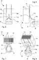
- a laser cutting head 1 is shown according to a first embodiment of the invention, which is arranged to be powered by a laser emission apparatus, of a known type and not shown in the figures, by means of optical transmission means and associable with a cutting machine tool.
- the emission apparatus is of solid-state laser stimulated emission type
- the optical transmission means comprises an optical fiber cable suitable for conveying the laser beam generated by the emission apparatus to the laser cutting head 1.
- the laser cutting head 1 comprises collimation means 2 for collimating the laser beam generated by the laser emission apparatus, focusing means 5 for focusing the collimated laser beam leaving the collimation means 2 and a casing 4 for containing and housing the focusing means 5.
- the laser cutting head 1 also comprises a cutting nozzle 18, that is fixed to the casing 4 by an optical centering ring-nut 19 and through which the focused laser beam comes out.
- the cutting nozzle 18 concentrates a blast or jet of gas for removing the dross generated by the fusion of the workpiece and at the same time limits the probability of this dross reaching the inside of the casing 4 and the focusing means 5.
- the collimation means 2 are of known type and comprises a set of lenses and a mirror capable of converging and collimating the laser beam coming from the optical fiber in a rectilinear laser beam directed towards the focusing means 5.
- the focusing means comprises at least one focusing lens 5.
- the laser cutting head 1 further includes supporting means 6 that is arranged to receive and hold the focusing lens 5 and is movable along an adjustment direction X inside the casing 4 to allow adjusting the focal point or focus of the laser beam coming out from the focusing lens 5.
- the supporting means includes a supporting element 6, which substantially acts as a carriage or slide for the focusing lens 5 and is housed inside a cavity 21 of the casing 4 wherein is slidably moved along the adjustment direction X by driving means 9.
- the driving means 9 includes, for example, a linear electric actuator or a recirculating ball screw operated by a rotary electric motor and coupled to the relative lead screw that is connected to the supporting element 6.
- the driving means 9 is fixed to the casing 4 and is connected to the supporting element 6 through an opening carried out in a side wall 4b of the casing 4.
- the supporting element 6 comprises a seat 7 suitable for receiving and locking the focusing lens 5.
- the laser cutting head 1 further comprises a cooling unit 10, which is externally fixed to the casing 4 and thermal conductive connecting means 11 arranged for connecting the supporting means 6 to the cooling unit 10 so as to extract by heat conduction from the supporting element 6 and the focusing lens 5 the heat that is generated by the laser beam when the latter passes through said focusing lens 5.
- the supporting element 6 is made of a thermal conductivity material, preferably a high thermal conductivity material such as aluminium alloy or brass, in order to allow the heat to be transferred from the focusing lens 5.
- the thermal conductive connecting means 11 comprises at least one flexible thermal conductive element made of high thermal conductivity material, for example a braided copper tape and/or graphite-coated tape.
- the flexible thermal conductive element 11 comprises a main portion 11a, which is fixed to the cooling unit 10 and from which two elongated portions 11b depart that are secured to opposite sides of supporting element 6.
- the flexible thermal conductive element 11 may comprise a single elongated portion 11b in addition to the main portion 11a.
- the flexibility of the thermal conductive element 11 in no way hinders the movement of the supporting element 6 along the adjustment direction X during operation of the laser cutting head 1 while the thermal conductivity material of the thermal conductive element 11 ensure an optimal heat extraction from the focusing lens 5.
- the cooling unit 10 comprises at least one Peltier cell 12 and a heat dissipation element 13.
- the flexible thermal conductive device 11 is connected to the cold side 12a of the Peltier cell 12, whereas the heat dissipation element 13 is connected to the hot side 12b of the Peltier cell 12.
- the Peltier cell is a thermoelectric device that acts as a solid-state heat pump and typically has the appearance of a thin plate: one of the two sides or faces of the plate absorbs heat while the other emits the heat. The direction in which the heat is transferred depends on the direction of the direct current applied at the ends of this plate. More precisely, a Peltier cell is composed of a plurality of Peltier junctions arranged in series to form a thin plate. The junction is formed of two doped semi-conductors, one N-type and one P-type, connected together by two opposing sheets of copper that form the outside faces or sides of the plate.
- the Peltier cell 12 used in the cooling unit 10 is of a known type.
- the laser head 1 comprises a cover 16 made of thermal conductivity material, preferably a high thermal conductivity material such as aluminium alloy or brass, to close an opening 17 of the casing 4 that gives access to the cavity 21 in which the supporting element 6 and the focusing lens 5 move.
- a cover 16 made of thermal conductivity material, preferably a high thermal conductivity material such as aluminium alloy or brass, to close an opening 17 of the casing 4 that gives access to the cavity 21 in which the supporting element 6 and the focusing lens 5 move.
- the cold side 12a of the Peltier cell 12 is fixed to an outer wall of the cover 16 and the flexible thermal conductive element 11 is fixed to the inner wall of the cover 16.
- the flexible thermal conductive element 11 can be directly fixed to the cold side 12a of the Peltier cell through a corresponding opening provided in the cover 16 ( figures 4-7 ).
- the cold side 12a of the Peltier cell 12 can be fixed to an external wall 4a, for example a front wall, of the casing 4 and the flexible thermal conductive element 11 can be directly fixed to the cold side 12a through a corresponding opening which is provided in the casing 4 and gives access to the cavity 21.
- the cooling unit 10 comprises a plurality of Peltier cells 12 arranged in series and/or parallel.
- the heat dissipation element 13 comprises a body made of high thermal conductivity material, such as aluminium alloy, provided with a plurality of cooling ducts 14 that allow the passage of air, in particular by convection, in order to cool the body itself.
- the heat dissipation element 13 has a parallelepiped shape and has a plurality of cooling ducts 14 arranged side by side and extending along a longitudinal direction, for example parallel to the adjustment direction X.
- the hot side 12b of the Peltier cell 12 is fixed to a rear wall of the heat dissipation element 13.
- Thermally conductive adhesives can be used to fix the thermal conductive connecting means 11 to the supporting means 6 and to the Peltier cell 12. More precisely, thermally conductive adhesives are used to fix the thermal conductive connecting means 11 to the supporting element 6 and to the cover 16 and/or to the cold side 12a of the Peltier cell and to fix the opposite sides 12a, 12b of the Peltier cell to the cover 16 and to the heat dissipation element 13.
- FIGS 8 to 11 show a version of the cooling unit 10 which comprises intake means 15 arranged for introducing a cooling fluid inside said cooling ducts 14 in order to increase the heat exchange (forced convection) and to cool the hot side 12b of the Peltier cell more quickly and effectively.
- the intake means 15 includes, for instance, a couple of nozzles supplied with compressed air and capable of introducing said compressed air into the cooling ducts 14.
- a diverter element 20 allows the flow of compressed air coming out from the nozzles 15 to be directed in the cooling ducts 14 so that the cooling fluid, i.e. the compressed air, leaves the heat exchange element 13 directed toward the workpiece.
- the heat generated in the focusing lens 5 by the passage of the laser beam coming out from the collimation means 3 (heat generated by the non-absolute transparency of the lens) is transferred and transmitted to the supporting element 6, to the thermal conductive connecting means 11 and to the cold side 12a of the Peltier cell 12.
- the heat is transferred from the focusing lens 5 to the Peltier cell 12, which transfer the heat to the heat dissipation element 13 (fixed to the hot side 12b of said Peltier cell 12).
- the focusing lens 5 transfers heat to the supporting element 6, which transfers heat to the flexible thermal conductive element 11.
- the heat extraction operated by the Peltier cell 12, which works as a heat pump, allows to control the temperature of the focusing lens 5 and in particular to prevent the overheating of the lens 5 with consequent variation of the lens refractive index and hence a focus shift.
- the laser cutting head 1 of the invention during operation, even long and intensive, allows to avoid thermal focus shift of the focusing lens 5 and therefore to focus the laser beam in the desired and optimal point with respect to the surface of the workpiece with cutting accuracy and efficiency.
- the temperature control and adjustment allows avoiding damage of the protective superficial layer of the focusing lens 5.
- the supporting means and the focusing lens can be effectively cooled by the Peltier cell while they move along the adjustment direction inside the casing for adjusting the focal point of the laser beam.
- the thermal efficiency of the cooling system of the laser cutting head disclosed in the present invention is comparable to that of the known gas cooling systems which remove heat from the lens by convection.
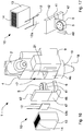
- a laser cutting head 1 is shown according to a second embodiment of the invention, which is arranged to be powered by a laser emission apparatus by means of optical transmission means and is associable with a cutting machine tool.
- the laser cutting head 1 comprises collimation means 2 for collimating the laser beam generated by the laser emission apparatus, focusing means 5 for focusing the collimated laser beam leaving the collimation means 2 and a casing 4 for containing and housing the focusing means 5.
- the laser cutting head 1 also comprises a cutting nozzle 18, that is fixed to the casing 4 for example by a ring-nut 19 and through which the focused laser beam comes out.
- the collimation means 2 are of known type and may comprise a set of lenses capable of converging and collimating the laser beam coming from the optical transmission means in a rectilinear laser beam.
- a mirror can be provided for redirecting the laser beam towards the focusing means 5 that comprises at least one focusing lens 5.
- the laser cutting head 1 comprises supporting means 6 arranged for receiving and holding said focusing lens 5 within a cavity 21 of said casing 4 and movable along an adjustment direction X so as to change a focal point or focus of the said laser beam coming out from said focusing means 5.
- the cavity 21 is provided with an accessing opening 17.
- the supporting means includes a supporting element 6 that is provided with a seat 7 suitable for receiving and holding the focusing lens 5.
- the laser cutting head 1 further includes according to the present invention a cooling unit 10, which is externally associated to the casing 4 and is provided with at least one Peltier cell 12 and a heat dissipation element 13, and thermal conductive connecting means 31 which is arranged for connecting the supporting means 6 to the cooling unit 10 so as to rigidly link said supporting means 6 and said cooling unit 10 and to extract by heat conduction from the supporting element 6 and the focusing lens 5 the heat that is generated by the laser beam passing through said focusing lens 5.
- the supporting element 6 is made of a thermal conductivity material, preferably a high thermal conductivity material such as aluminium alloy or brass.
- the Peltier cell 12 comprises a cold side 12a that is connected to the thermal conductive connecting means 31, 32 and a hot side 12b that is connected to the heat dissipation element 13.
- the heat dissipation element 13 has a body made of high thermal conductivity material, such as aluminium alloy, and is provided with a plurality of cooling ducts 14 that allow the passage of air, in particular by natural or forced convection, to cool the body itself.
- the cooling unit 10 may also comprise a plurality of Peltier cells 12 arranged in parallel and/or in series.
- the laser cutting head 1 includes a moving element 37 that supports the thermal conductive connecting means 31 and/or the cooling unit 10 and is slidably coupled to an external wall 4a, for example the front wall, of the casing 4 and is movable along the adjustment direction X so as to move the supporting means 6 and the focusing means 5.
- Driving means 9 is fixed to the casing 4 and coupled to the moving element 37 so as to move the latter along said adjustment direction X.
- the thermal conductive connecting means comprises a first connecting element 31 and a second connecting element 32 both made of a thermal conductivity material, preferably a high thermal conductivity material such as aluminium alloy or brass.
- the first connecting element 31 is provided with a first end fixed to, and holding, the supporting element 6 and a second end fixed to the second connecting element 32, the latter being connected to the Peltier cell 12, in particular to a cold side 12a thereof.
- the first connecting element 31 is shaped substantially as an elongated bracket or arm which is connected to the second connecting element 32, for example detachably by suitable fastening means.
- the first connecting element 31 and second connecting element 32 can be also made integral.
- the second connecting element 32 has a flat shape with an inner surface to which the first connecting element 31 is fastened and an external surface which is connected to the cold side 12a of the Peltier cell 12.
- the flat shape and the dimensions of the second connecting element 32 allow an efficient and high thermal exchange between the thermal conductive connecting means 31, 32 (together with the supporting element 6 and the focusing lens 5) and the Peltier cell 12.
- Thermally conductive adhesives can be used to mutually fix the external surface of the second connecting element 32 and the cold side 12a of the Peltier cell 12.
- the moving element 37 is coupled to the second connecting element 32 so as to move the latter together with the first connecting element 31, the supporting element 6 and the focusing lens 5 and the cooling unit 10.
- the moving element 37 can directly support the cooling unit 10 and the latter can support the supporting element 6 and the focusing lens 5 by means of the connecting elements 31, 32.
- the moving element 37 comprises a flat element that is slidably coupled to the external wall 4a, i.e. a front wall, of the casing 4 and is provided with a respective opening 37a that gives access to the cavity 21 of the casing 4. More precisely, the opening 37a of the moving element 37 allows the connecting elements 31, 32 to rigidly connect the cooling unit 10 to the supporting element 6.
- the moving element 37 has a linking arm 38 that is coupled to the driving means 9.
- the latter is fixed to a side wall 4b of the casing 4 and includes for example, a linear electric actuator or a recirculating ball screw operated by a rotary electric motor and connected to the relative lead screw fastened to the linking arm 38.
- the heat generated in the focusing lens 5 by the passage of the laser beam coming out from the collimation means 2 (heat generated by the non-absolute transparency of lens) is transferred and transmitted to the supporting element 6, to the thermal conductive connecting means 31, 32 and then to the cold side 12a of the Peltier cell 12. Then the Peltier cell 12 transfers the heat of the focusing lens to the heat dissipation element 13 that is fixed to the hot side 12b.
- the Peltier cell 12 allows controlling the temperature of the focusing lens 5 and in particular to prevent the overheating of the focusing lens 5 with consequent variation of the lens refractive index and hence a focus shift.
- the intensity and voltage of the direct or PWD (pulse-width modulation) electrical current, which powers the Peltier cell 12 it is possible to control the temperature of the focusing lens 5 in an accurate and reliable manner.
- the laser cutting head 1 of the invention during operation, even long and intensive, allows to avoid thermal focus shift of the focusing lens 5 and therefore to focus the laser beam in the desired and optimum point with respect to the surface of the work piece with cutting accuracy and efficiency.
- the temperature control and adjustment can help to prevent damage of the protective superficial layer of the focusing lens 5.
- thermal conductive connecting means and the moving element make possible both to control the temperature of the focusing lens (by means of the Peltier cell) and to move the supporting means and the focusing lens along the adjustment direction in order to adjust the focal point of the laser beam.
- connecting elements 31, 32 can be disconnected from the moving element 37 allowing to easily and quickly remove from the laser cutting head 1 both the cooling unit 10 and the supporting element 6 with the focusing lens 5, for maintenance and/or controls.
- Figures 15 to 17 show a variant of the laser cutting head 1, which differs from the second embodiment of figure 12 to 14 and above described for the different thermal conductive connecting means 41, 42 and the moving element 47.
- the second connecting element 42 of the thermal conductive connecting means and the moving element 47 are mutually fixed so as to form a flat shaped element of which an inner surface is coupled to the first connecting element 41 of the thermal conductive connecting means and an external surface is connected to the cold side 12a of the Peltier cell.
- the second connecting element 42 and the moving element 47 can be also made integral and in a high thermal conductivity material.
- the moving element 47 has a linking arm 48 that is coupled to the driving means 9.
- FIG 18 shows another variant of the laser cutting head 1 of the invention, wherein the cooling unit 10 further comprises intake means 15 arranged for introducing a cooling fluid inside said cooling ducts 14 of the heat dissipation element 13 in order to increase the heat exchange (forced convection) and to cool the hot side 12b of the Peltier cell more quickly and effectively.
- the intake means 15 includes, for instance, a couple of nozzles supplied with compressed air and capable of introducing the said expanded air in the cooling ducts 14.
- a diverter element 20 allows the flow of compressed air coming out from the nozzles 15 to be directed in the cooling ducts 14 so that the cooling fluid, that is the air, leaves the heat exchange element 13.
Landscapes
- Physics & Mathematics (AREA)
- Optics & Photonics (AREA)
- Engineering & Computer Science (AREA)
- Plasma & Fusion (AREA)
- Mechanical Engineering (AREA)
- General Physics & Mathematics (AREA)
- Laser Beam Processing (AREA)
Claims (13)
- Tête de découpe laser actionnée par un appareil d'émission laser au moyen de moyens de transmission optiques et associable à une machine-outil de découpe, incluant :- un moyen de collimation (2) pour collimater un faisceau laser venant dudit appareil d'émission laser ;- un moyen de focalisation (5) pour focaliser un faisceau laser collimaté sortant dudit moyen de collimation (2) ;- un boîtier (4) pour recevoir et contenir ledit moyen de focalisation (5) ;- un moyen de support (6) pour recevoir et contenir ledit moyen de focalisation (5) dans une cavité (21) dudit boîtier (4) et mobile le long d'une direction d'ajustement (X) de sorte à changer un point focal dudit faisceau laser sortant dudit moyen de focalisation (5) ;ladite tête de découpe laser (1) étant caractérisée en ce qu'elle comprend :- une unité de refroidissement (10) comprenant au moins une cellule Peltier (12) et un élément de dissipation thermique (13) et associée à l'extérieur au boîtier (4) ;- un moyen de connexion thermoconducteur (31, 41 ; 32, 42) agencé pour relier ledit moyen de support (6) à ladite unité de refroidissement (10) de sorte à relier rigidement ledit moyen de support (6) et ladite unité de refroidissement (10) et à extraire par conduction thermique dudit moyen de support (6) et dudit moyen de focalisation (5) la chaleur générée par ledit faisceau laser passant au travers dudit moyen de focalisation (5), dans lequel ledit moyen de support (6) est réalisé en un matériau thermoconducteur ;- un élément mobile (37 ; 47) qui supporte ledit moyen de connexion thermoconducteur (31, 41 ; 32, 42) et/ou ladite unité de refroidissement (10) et est couplé de manière coulissante à une paroi externe (4a) dudit boîtier (4) et mobile le long de ladite direction d'ajustement (X) de sorte à déplacer ledit moyen de support (6) et ledit moyen de focalisation (5).
- Tête de découpe laser selon la revendication 1, dans laquelle ledit moyen de connexion thermoconducteur (31, 32 ; 41, 42) comprend un premier élément de connexion (31 ; 41) et un second élément de connexion (32 ; 42), dont les deux sont fabriqués en un matériau thermoconducteur, ledit premier élément de connexion (31 ; 41) présentant une première extrémité fixée audit moyen de support (6) et le contenant, et une seconde extrémité fixée audit second élément de connexion (32 ; 42) qui est connecté à ladite cellule Peltier (12).
- Tête de découpe laser selon la revendication 2, dans laquelle ledit élément mobile (37 ; 47) est couplé audit second élément de connexion (32 ; 42).
- Tête de découpe laser selon la revendication 2 ou 3, dans laquelle ledit élément mobile (37) est doté d'une ouverture respective (37a) permettant audit élément de connexion (31, 32) de relier ledit moyen de support (6) et ladite cellule Peltier (12).
- Tête de découpe laser selon la revendication 3, dans laquelle ledit second élément de connexion (42) et ledit élément mobile (47) sont formés intégralement et réalisés en un matériau thermoconducteur.
- Tête de découpe laser selon l'une quelconque des revendications 2 à 5, dans laquelle ledit second élément de connexion (32 ; 42) et/ou ledit élément mobile (37 ; 47) ferme hermétiquement une ouverture (17) de ladite cavité (21).
- Tête de découpe laser selon une quelconque revendication précédente, dans laquelle ladite cellule Peltier (12) comprend un côté froid (12a) relié audit moyen de connexion thermoconducteur (31, 32 ; 41, 42) et un côté chaud (12b) relié audit élément de dissipation thermique (13).
- Tête de découpe laser selon une quelconque revendication précédente, comprenant un moyen d'entraînement (9) fixé à un dit boîtier (4) et couplé audit élément mobile (37 ; 47) de sorte à déplacer ce dernier le long de ladite direction d'ajustement (X).
- Tête de découpe laser selon une quelconque revendication précédente, dans laquelle ledit moyen de focalisation comprend au moins une lentille de focalisation (5).
- Tête de découpe laser selon une quelconque revendication précédente, dans laquelle ladite unité de refroidissement (10) comprend une pluralité de cellules Peltier (12) qui sont agencées parallèlement et/ou en série.
- Tête de découpe laser selon une quelconque revendication précédente, dans laquelle ledit élément de dissipation thermique (13) comprend une pluralité de conduits de refroidissement (14) pour le passage d'air, en particulier au moyen de la convection.
- Tête de découpe laser selon la revendication 11, comprenant un moyen d'admission (15) pour l'introduction d'un fluide de refroidissement, en particulier de l'air comprimé, dans lesdits conduits de refroidissement (14).
- Machine-outil de découpe et/ou de poinçonnage comprenant au moins une tête de découpe laser (1) selon l'une quelconque des revendications 1 à 12.
Priority Applications (2)
| Application Number | Priority Date | Filing Date | Title |
|---|---|---|---|
| PL14809305T PL3071362T3 (pl) | 2013-11-22 | 2014-11-20 | Laserowa głowica tnąca z przymocowaną do niej jednostką chłodzącą; laserowe mechaniczne narzędzie tnące i/albo wykrawające z taką laserową głowicą tnącą |
| EP14809305.7A EP3071362B1 (fr) | 2013-11-22 | 2014-11-20 | Tête de découpe laser avec une unité de refoidissement fixée à la tête ; machine-outil de découpe et/ou poinconnage avec une telle tête de découpe laser |
Applications Claiming Priority (3)
| Application Number | Priority Date | Filing Date | Title |
|---|---|---|---|
| EP13194090.0A EP2875896B1 (fr) | 2013-11-22 | 2013-11-22 | Tête de coupe au laser pour machine-outil avec une unité de refoidissement fixée à la tête |
| PCT/EP2014/075209 WO2015075152A1 (fr) | 2013-11-22 | 2014-11-20 | Tête de découpage au laser pour machine-outil |
| EP14809305.7A EP3071362B1 (fr) | 2013-11-22 | 2014-11-20 | Tête de découpe laser avec une unité de refoidissement fixée à la tête ; machine-outil de découpe et/ou poinconnage avec une telle tête de découpe laser |
Publications (2)
| Publication Number | Publication Date |
|---|---|
| EP3071362A1 EP3071362A1 (fr) | 2016-09-28 |
| EP3071362B1 true EP3071362B1 (fr) | 2018-01-10 |
Family
ID=49766853
Family Applications (2)
| Application Number | Title | Priority Date | Filing Date |
|---|---|---|---|
| EP13194090.0A Active EP2875896B1 (fr) | 2013-11-22 | 2013-11-22 | Tête de coupe au laser pour machine-outil avec une unité de refoidissement fixée à la tête |
| EP14809305.7A Active EP3071362B1 (fr) | 2013-11-22 | 2014-11-20 | Tête de découpe laser avec une unité de refoidissement fixée à la tête ; machine-outil de découpe et/ou poinconnage avec une telle tête de découpe laser |
Family Applications Before (1)
| Application Number | Title | Priority Date | Filing Date |
|---|---|---|---|
| EP13194090.0A Active EP2875896B1 (fr) | 2013-11-22 | 2013-11-22 | Tête de coupe au laser pour machine-outil avec une unité de refoidissement fixée à la tête |
Country Status (11)
| Country | Link |
|---|---|
| US (1) | US10173285B2 (fr) |
| EP (2) | EP2875896B1 (fr) |
| JP (1) | JP6231684B2 (fr) |
| KR (2) | KR101913481B1 (fr) |
| CN (1) | CN105745050B (fr) |
| BR (1) | BR112016011479B1 (fr) |
| DK (2) | DK2875896T3 (fr) |
| ES (2) | ES2608034T3 (fr) |
| PL (2) | PL2875896T3 (fr) |
| RU (1) | RU2653892C2 (fr) |
| WO (1) | WO2015075152A1 (fr) |
Cited By (1)
| Publication number | Priority date | Publication date | Assignee | Title |
|---|---|---|---|---|
| DE102018114369B4 (de) * | 2017-06-23 | 2024-12-05 | PT Photonic Tools GmbH | Laser-bearbeitungskopf und verfahren zum austausch von optischen komponenten |
Families Citing this family (36)
| Publication number | Priority date | Publication date | Assignee | Title |
|---|---|---|---|---|
| CN104985332B (zh) * | 2015-07-10 | 2017-01-25 | 青岛星华智能装备有限公司 | 激光切割机的封闭检测方法 |
| WO2017075566A1 (fr) | 2015-10-30 | 2017-05-04 | Hypertherm, Inc. | Double buse pour tête de traitement laser |
| US11850681B2 (en) | 2015-10-30 | 2023-12-26 | Hypertherm, Inc. | Highly positioned laser processing nozzle |
| US10525554B2 (en) | 2015-10-30 | 2020-01-07 | Hypertherm, Inc. | Water cooling of laser components |
| US10569360B2 (en) | 2015-10-30 | 2020-02-25 | Hypertherm, Inc. | Highly positioned laser processing nozzle |
| KR20170087610A (ko) * | 2016-01-21 | 2017-07-31 | 삼성전자주식회사 | 웨이퍼 절단 장치 |
| LT3468742T (lt) * | 2016-06-14 | 2022-12-12 | Evana Technologies, Uab | Daugiasegmentis fokusavimo lęšis ir lazerinio apdirbimo sistema plokštelių sudalinimui arba pjaustymui |
| FR3054972B1 (fr) * | 2016-08-12 | 2019-01-25 | Accelinn | Dispositif de traitement d'une surface ou d'une zone par faisceau laser avec systeme de maintien thermique |
| CN107671433B (zh) * | 2017-09-27 | 2019-08-23 | 济南邦德激光股份有限公司 | 一种具备废料收集装置的激光切割机 |
| IT201700121730A1 (it) * | 2017-10-26 | 2019-04-26 | Salvagnini Italia Spa | Testa di taglio laser per macchina utensile |
| JP6999401B2 (ja) * | 2017-12-19 | 2022-01-18 | 東京エレクトロン株式会社 | レーザー加工装置 |
| CN108176927A (zh) * | 2018-02-02 | 2018-06-19 | 苏州钋镭自动化科技有限公司 | 激光切割头 |
| CN108838555A (zh) * | 2018-06-01 | 2018-11-20 | 苏州福唐智能科技有限公司 | 一种用于激光切割设备的激光头 |
| CN109865945B (zh) * | 2019-01-25 | 2024-03-22 | 苏州迅镭激光科技有限公司 | 一种具有冷却散热功能的激光切割头 |
| CN109773350B (zh) * | 2019-01-25 | 2024-03-22 | 苏州迅镭激光科技有限公司 | 一种激光切割头气冷散热装置 |
| DE102019112167A1 (de) | 2019-05-09 | 2020-11-12 | Trumpf Laser Gmbh | Bearbeitungskopf zur Führung eines Laserstrahls sowie Laserbearbeitungsvorrichtung mit einem Bearbeitungskopf |
| US11426817B2 (en) * | 2019-09-26 | 2022-08-30 | Toyota Motor Engineering & Manufacturing North America, Inc. | Lock and fail-safe for laser welding lens |
| KR102691408B1 (ko) * | 2020-02-07 | 2024-08-05 | 살바그니니 이탈리아 에스.피.에이. | 기계 공구를 위한 레이저 절단 헤드 |
| IT202000008386A1 (it) * | 2020-04-20 | 2021-10-20 | Prima Ind Spa | Terminale operativo laser, macchina operatrice laser e procedimento di fabbricazione corrispondenti |
| CN111604585A (zh) * | 2020-06-10 | 2020-09-01 | 广州新可激光设备有限公司 | 一种激光打标z轴调焦模块的横向冷却系统 |
| CN111922530A (zh) * | 2020-08-09 | 2020-11-13 | 刘琳 | 一种纺织面料用高散热型激光切割机切割方法 |
| CN112975146A (zh) * | 2021-02-05 | 2021-06-18 | 浙江头鲸激光智能制造有限公司 | 一种使用方便的激光切割机 |
| CN113020787B (zh) * | 2021-05-18 | 2021-08-17 | 岗春激光科技(江苏)有限公司 | 一种镜筒及激光切割头 |
| CN113814579A (zh) * | 2021-10-13 | 2021-12-21 | 无锡新松机器人自动化有限公司 | 一种新型三维五轴激光切割头结构 |
| CN113977114A (zh) * | 2021-10-13 | 2022-01-28 | 无锡新松机器人自动化有限公司 | 一种用于三维五轴激光切割机的防碰撞机构 |
| CN114289896A (zh) * | 2021-12-30 | 2022-04-08 | 杨未来 | 一种具有自循环式高效物理循环冷却激光切割头 |
| CN114722550B (zh) * | 2022-05-19 | 2022-08-23 | 北京精雕科技集团有限公司 | 冷却管路排布方法、装置、电子设备及存储介质 |
| KR102636880B1 (ko) * | 2023-02-17 | 2024-02-14 | 전호대 | 절삭유를 사용하지 않는 메탈 로드 커팅장치 |
| USD1122313S1 (en) | 2023-05-25 | 2026-04-14 | Hypertherm, Inc. | Nozzle for a laser processing system |
| USD1124062S1 (en) | 2023-05-25 | 2026-04-28 | Hypertherm, Inc. | Nozzle for a laser processing system |
| USD1118718S1 (en) | 2024-03-28 | 2026-03-17 | Hypertherm, Inc. | Nozzle for a laser cutting system |
| USD1114001S1 (en) | 2024-03-28 | 2026-02-17 | Hypertherm, Inc. | Nozzle for a laser cutting system |
| USD1114849S1 (en) | 2024-03-28 | 2026-02-24 | Hypertherm, Inc. | Nozzle for a laser cutting system |
| CN118720458B (zh) * | 2024-08-12 | 2025-01-28 | 苏州都源精密机械有限公司 | 一种金属零件的激光切割装置 |
| CN119525759A (zh) * | 2024-11-29 | 2025-02-28 | 武汉锐科光纤激光技术股份有限公司 | 一种金刚石紫铜复合材料的加工方法及系统 |
| CN120395184B (zh) * | 2025-06-05 | 2026-03-27 | 苏州瑞铁激光科技有限公司 | 一种具有冷却机构的激光切割机 |
Family Cites Families (15)
| Publication number | Priority date | Publication date | Assignee | Title |
|---|---|---|---|---|
| CH642891A5 (de) * | 1979-11-21 | 1984-05-15 | Laser Work Ag | Verfahren und vorrichtung zur bearbeitung eines werkstuecks mittels laserstrahl. |
| RU1568390C (ru) * | 1988-12-26 | 1995-03-20 | Научно-исследовательский центр по технологическим лазерам | Устройство для крепления и смены оптических головок лазерных технологических комплексов |
| DE19827602A1 (de) * | 1998-06-20 | 1999-12-23 | Zeiss Carl Fa | Verfahren zur Korrektur nicht-rotationssymmetrischer Bildfehler |
| JP4667645B2 (ja) * | 2001-05-30 | 2011-04-13 | 株式会社アマダ | ミラー温度制御機構を有するレーザー加工機及びレーザー加工機のミラー温度制御方法 |
| UA47198C2 (en) * | 2001-08-31 | 2004-06-15 | Yurii Vasyliovych Popadynets | Lightguide and the method of using the ligthguide |
| JP3845650B1 (ja) * | 2005-06-13 | 2006-11-15 | 株式会社日本製鋼所 | レーザ照射方法及びその装置 |
| CN103193222B (zh) * | 2007-05-17 | 2015-08-12 | 株式会社钟化 | 石墨膜及石墨复合膜 |
| ES2364025T3 (es) * | 2008-11-10 | 2011-08-23 | Jenoptik Automatisierungstechnik Gmbh | Dispositivo para el mecanizado en 3d altamente dinámico de una pieza con un rayo láser. |
| JP2010142859A (ja) * | 2008-12-22 | 2010-07-01 | Olympus Corp | レーザ照射装置およびレーザ加工機 |
| RU2386523C1 (ru) * | 2008-12-25 | 2010-04-20 | Открытое акционерное общество Национальный институт авиационных технологий (ОАО НИАТ) | Устройство для резки волоконным лазером объемных деталей |
| JP5419818B2 (ja) * | 2010-07-14 | 2014-02-19 | 三菱電機株式会社 | レーザ加工機 |
| JP5651398B2 (ja) * | 2010-07-23 | 2015-01-14 | 株式会社アマダ | ファイバレーザ加工機の加工ヘッド |
| JP5707092B2 (ja) * | 2010-10-26 | 2015-04-22 | パナソニック デバイスSunx株式会社 | レーザ加工装置 |
| CN201913388U (zh) * | 2010-11-23 | 2011-08-03 | 武汉楚天激光(集团)股份有限公司 | 用于激光切割机的风冷切割头 |
| CN103534056B (zh) * | 2011-05-19 | 2016-01-13 | 村田机械株式会社 | 激光加工机 |
-
2013
- 2013-11-22 PL PL13194090T patent/PL2875896T3/pl unknown
- 2013-11-22 DK DK13194090.0T patent/DK2875896T3/en active
- 2013-11-22 ES ES13194090.0T patent/ES2608034T3/es active Active
- 2013-11-22 EP EP13194090.0A patent/EP2875896B1/fr active Active
-
2014
- 2014-11-20 BR BR112016011479-5A patent/BR112016011479B1/pt active IP Right Grant
- 2014-11-20 US US15/036,197 patent/US10173285B2/en active Active
- 2014-11-20 ES ES14809305.7T patent/ES2665582T3/es active Active
- 2014-11-20 PL PL14809305T patent/PL3071362T3/pl unknown
- 2014-11-20 EP EP14809305.7A patent/EP3071362B1/fr active Active
- 2014-11-20 KR KR1020167016593A patent/KR101913481B1/ko active Active
- 2014-11-20 JP JP2016533202A patent/JP6231684B2/ja active Active
- 2014-11-20 WO PCT/EP2014/075209 patent/WO2015075152A1/fr not_active Ceased
- 2014-11-20 DK DK14809305.7T patent/DK3071362T3/en active
- 2014-11-20 CN CN201480063823.7A patent/CN105745050B/zh active Active
- 2014-11-20 KR KR1020187030811A patent/KR20180118819A/ko not_active Ceased
- 2014-11-20 RU RU2016123331A patent/RU2653892C2/ru active
Cited By (1)
| Publication number | Priority date | Publication date | Assignee | Title |
|---|---|---|---|---|
| DE102018114369B4 (de) * | 2017-06-23 | 2024-12-05 | PT Photonic Tools GmbH | Laser-bearbeitungskopf und verfahren zum austausch von optischen komponenten |
Also Published As
| Publication number | Publication date |
|---|---|
| EP3071362A1 (fr) | 2016-09-28 |
| US10173285B2 (en) | 2019-01-08 |
| PL2875896T3 (pl) | 2017-06-30 |
| ES2665582T3 (es) | 2018-04-26 |
| ES2608034T3 (es) | 2017-04-05 |
| RU2016123331A (ru) | 2017-12-25 |
| CN105745050A (zh) | 2016-07-06 |
| BR112016011479A2 (fr) | 2017-08-08 |
| KR20160083122A (ko) | 2016-07-11 |
| KR20180118819A (ko) | 2018-10-31 |
| EP2875896B1 (fr) | 2016-10-05 |
| KR101913481B1 (ko) | 2018-10-30 |
| BR112016011479B1 (pt) | 2022-03-22 |
| CN105745050B (zh) | 2018-01-09 |
| DK2875896T3 (en) | 2017-01-23 |
| JP2016539007A (ja) | 2016-12-15 |
| JP6231684B2 (ja) | 2017-11-15 |
| DK3071362T3 (en) | 2018-04-23 |
| PL3071362T3 (pl) | 2018-07-31 |
| EP2875896A1 (fr) | 2015-05-27 |
| RU2653892C2 (ru) | 2018-05-15 |
| US20160288267A1 (en) | 2016-10-06 |
| WO2015075152A1 (fr) | 2015-05-28 |
Similar Documents
| Publication | Publication Date | Title |
|---|---|---|
| EP3071362B1 (fr) | Tête de découpe laser avec une unité de refoidissement fixée à la tête ; machine-outil de découpe et/ou poinconnage avec une telle tête de découpe laser | |
| US9731381B2 (en) | Laser cutting head for machine tool | |
| JP6445213B2 (ja) | ラインビーム光源およびラインビーム照射装置ならびにレーザリフトオフ方法 | |
| ES2927973T3 (es) | Aparato de mecanizado por láser y procedimiento de mecanizado por láser | |
| US11679448B2 (en) | Beam-forming units with cooling systems for high-power lasers | |
| KR20180137045A (ko) | 가공 장치 및 가공 방법 | |
| WO2019082110A1 (fr) | Tête de découpage au laser pour machines-outils | |
| CN102123817A (zh) | 去角加工装置 | |
| US9214368B2 (en) | Laser diode array with fiber optic termination for surface treatment of materials | |
| US20170203388A1 (en) | Laser machining system and laser machining method | |
| JP2016081994A (ja) | ダイレクトダイオードレーザ発振器 | |
| KR20140061198A (ko) | 레이저 장치 | |
| CN223876275U (zh) | 激光装置及激光加工设备 | |
| KR102807317B1 (ko) | 15mm 용접비드폭형 쓰리와이어식 스마트 파이버레이저 용접장치 및 방법 | |
| Kubacki et al. | Successful diode laser material processing using application specific micro-optical beam shaping | |
| WO2004108342A2 (fr) | Procede et appareil de soudage par points au laser | |
| JP2023168639A (ja) | レーザー照射方法 | |
| CN108963730A (zh) | 一种光纤紫外激光器 |
Legal Events
| Date | Code | Title | Description |
|---|---|---|---|
| PUAI | Public reference made under article 153(3) epc to a published international application that has entered the european phase |
Free format text: ORIGINAL CODE: 0009012 |
|
| 17P | Request for examination filed |
Effective date: 20160621 |
|
| AK | Designated contracting states |
Kind code of ref document: A1 Designated state(s): AL AT BE BG CH CY CZ DE DK EE ES FI FR GB GR HR HU IE IS IT LI LT LU LV MC MK MT NL NO PL PT RO RS SE SI SK SM TR |
|
| AX | Request for extension of the european patent |
Extension state: BA ME |
|
| DAX | Request for extension of the european patent (deleted) | ||
| GRAP | Despatch of communication of intention to grant a patent |
Free format text: ORIGINAL CODE: EPIDOSNIGR1 |
|
| STAA | Information on the status of an ep patent application or granted ep patent |
Free format text: STATUS: GRANT OF PATENT IS INTENDED |
|
| INTG | Intention to grant announced |
Effective date: 20170802 |
|
| GRAS | Grant fee paid |
Free format text: ORIGINAL CODE: EPIDOSNIGR3 |
|
| GRAA | (expected) grant |
Free format text: ORIGINAL CODE: 0009210 |
|
| STAA | Information on the status of an ep patent application or granted ep patent |
Free format text: STATUS: THE PATENT HAS BEEN GRANTED |
|
| AK | Designated contracting states |
Kind code of ref document: B1 Designated state(s): AL AT BE BG CH CY CZ DE DK EE ES FI FR GB GR HR HU IE IS IT LI LT LU LV MC MK MT NL NO PL PT RO RS SE SI SK SM TR |
|
| REG | Reference to a national code |
Ref country code: CH Ref legal event code: EP Ref country code: AT Ref legal event code: REF Ref document number: 961859 Country of ref document: AT Kind code of ref document: T Effective date: 20180115 |
|
| REG | Reference to a national code |
Ref country code: IE Ref legal event code: FG4D |
|
| REG | Reference to a national code |
Ref country code: DE Ref legal event code: R096 Ref document number: 602014019903 Country of ref document: DE |
|
| REG | Reference to a national code |
Ref country code: DK Ref legal event code: T3 Effective date: 20180416 |
|
| REG | Reference to a national code |
Ref country code: ES Ref legal event code: FG2A Ref document number: 2665582 Country of ref document: ES Kind code of ref document: T3 Effective date: 20180426 |
|
| REG | Reference to a national code |
Ref country code: SE Ref legal event code: TRGR |
|
| REG | Reference to a national code |
Ref country code: NL Ref legal event code: MP Effective date: 20180110 |
|
| PG25 | Lapsed in a contracting state [announced via postgrant information from national office to epo] |
Ref country code: NL Free format text: LAPSE BECAUSE OF FAILURE TO SUBMIT A TRANSLATION OF THE DESCRIPTION OR TO PAY THE FEE WITHIN THE PRESCRIBED TIME-LIMIT Effective date: 20180110 |
|
| PG25 | Lapsed in a contracting state [announced via postgrant information from national office to epo] |
Ref country code: NO Free format text: LAPSE BECAUSE OF FAILURE TO SUBMIT A TRANSLATION OF THE DESCRIPTION OR TO PAY THE FEE WITHIN THE PRESCRIBED TIME-LIMIT Effective date: 20180410 Ref country code: HR Free format text: LAPSE BECAUSE OF FAILURE TO SUBMIT A TRANSLATION OF THE DESCRIPTION OR TO PAY THE FEE WITHIN THE PRESCRIBED TIME-LIMIT Effective date: 20180110 Ref country code: LT Free format text: LAPSE BECAUSE OF FAILURE TO SUBMIT A TRANSLATION OF THE DESCRIPTION OR TO PAY THE FEE WITHIN THE PRESCRIBED TIME-LIMIT Effective date: 20180110 Ref country code: CY Free format text: LAPSE BECAUSE OF FAILURE TO SUBMIT A TRANSLATION OF THE DESCRIPTION OR TO PAY THE FEE WITHIN THE PRESCRIBED TIME-LIMIT Effective date: 20180110 |
|
| PG25 | Lapsed in a contracting state [announced via postgrant information from national office to epo] |
Ref country code: IS Free format text: LAPSE BECAUSE OF FAILURE TO SUBMIT A TRANSLATION OF THE DESCRIPTION OR TO PAY THE FEE WITHIN THE PRESCRIBED TIME-LIMIT Effective date: 20180510 Ref country code: BG Free format text: LAPSE BECAUSE OF FAILURE TO SUBMIT A TRANSLATION OF THE DESCRIPTION OR TO PAY THE FEE WITHIN THE PRESCRIBED TIME-LIMIT Effective date: 20180410 Ref country code: GR Free format text: LAPSE BECAUSE OF FAILURE TO SUBMIT A TRANSLATION OF THE DESCRIPTION OR TO PAY THE FEE WITHIN THE PRESCRIBED TIME-LIMIT Effective date: 20180411 Ref country code: LV Free format text: LAPSE BECAUSE OF FAILURE TO SUBMIT A TRANSLATION OF THE DESCRIPTION OR TO PAY THE FEE WITHIN THE PRESCRIBED TIME-LIMIT Effective date: 20180110 Ref country code: RS Free format text: LAPSE BECAUSE OF FAILURE TO SUBMIT A TRANSLATION OF THE DESCRIPTION OR TO PAY THE FEE WITHIN THE PRESCRIBED TIME-LIMIT Effective date: 20180110 |
|
| REG | Reference to a national code |
Ref country code: DE Ref legal event code: R097 Ref document number: 602014019903 Country of ref document: DE |
|
| PG25 | Lapsed in a contracting state [announced via postgrant information from national office to epo] |
Ref country code: EE Free format text: LAPSE BECAUSE OF FAILURE TO SUBMIT A TRANSLATION OF THE DESCRIPTION OR TO PAY THE FEE WITHIN THE PRESCRIBED TIME-LIMIT Effective date: 20180110 Ref country code: AL Free format text: LAPSE BECAUSE OF FAILURE TO SUBMIT A TRANSLATION OF THE DESCRIPTION OR TO PAY THE FEE WITHIN THE PRESCRIBED TIME-LIMIT Effective date: 20180110 Ref country code: RO Free format text: LAPSE BECAUSE OF FAILURE TO SUBMIT A TRANSLATION OF THE DESCRIPTION OR TO PAY THE FEE WITHIN THE PRESCRIBED TIME-LIMIT Effective date: 20180110 |
|
| PLBE | No opposition filed within time limit |
Free format text: ORIGINAL CODE: 0009261 |
|
| STAA | Information on the status of an ep patent application or granted ep patent |
Free format text: STATUS: NO OPPOSITION FILED WITHIN TIME LIMIT |
|
| PG25 | Lapsed in a contracting state [announced via postgrant information from national office to epo] |
Ref country code: CZ Free format text: LAPSE BECAUSE OF FAILURE TO SUBMIT A TRANSLATION OF THE DESCRIPTION OR TO PAY THE FEE WITHIN THE PRESCRIBED TIME-LIMIT Effective date: 20180110 Ref country code: SM Free format text: LAPSE BECAUSE OF FAILURE TO SUBMIT A TRANSLATION OF THE DESCRIPTION OR TO PAY THE FEE WITHIN THE PRESCRIBED TIME-LIMIT Effective date: 20180110 Ref country code: SK Free format text: LAPSE BECAUSE OF FAILURE TO SUBMIT A TRANSLATION OF THE DESCRIPTION OR TO PAY THE FEE WITHIN THE PRESCRIBED TIME-LIMIT Effective date: 20180110 |
|
| 26N | No opposition filed |
Effective date: 20181011 |
|
| PG25 | Lapsed in a contracting state [announced via postgrant information from national office to epo] |
Ref country code: SI Free format text: LAPSE BECAUSE OF FAILURE TO SUBMIT A TRANSLATION OF THE DESCRIPTION OR TO PAY THE FEE WITHIN THE PRESCRIBED TIME-LIMIT Effective date: 20180110 |
|
| PG25 | Lapsed in a contracting state [announced via postgrant information from national office to epo] |
Ref country code: LU Free format text: LAPSE BECAUSE OF NON-PAYMENT OF DUE FEES Effective date: 20181120 Ref country code: MC Free format text: LAPSE BECAUSE OF FAILURE TO SUBMIT A TRANSLATION OF THE DESCRIPTION OR TO PAY THE FEE WITHIN THE PRESCRIBED TIME-LIMIT Effective date: 20180110 |
|
| REG | Reference to a national code |
Ref country code: BE Ref legal event code: MM Effective date: 20181130 |
|
| REG | Reference to a national code |
Ref country code: IE Ref legal event code: MM4A |
|
| PG25 | Lapsed in a contracting state [announced via postgrant information from national office to epo] |
Ref country code: IE Free format text: LAPSE BECAUSE OF NON-PAYMENT OF DUE FEES Effective date: 20181120 |
|
| PG25 | Lapsed in a contracting state [announced via postgrant information from national office to epo] |
Ref country code: BE Free format text: LAPSE BECAUSE OF NON-PAYMENT OF DUE FEES Effective date: 20181130 |
|
| PG25 | Lapsed in a contracting state [announced via postgrant information from national office to epo] |
Ref country code: MT Free format text: LAPSE BECAUSE OF NON-PAYMENT OF DUE FEES Effective date: 20181120 |
|
| REG | Reference to a national code |
Ref country code: AT Ref legal event code: UEP Ref document number: 961859 Country of ref document: AT Kind code of ref document: T Effective date: 20180110 |
|
| PG25 | Lapsed in a contracting state [announced via postgrant information from national office to epo] |
Ref country code: PT Free format text: LAPSE BECAUSE OF FAILURE TO SUBMIT A TRANSLATION OF THE DESCRIPTION OR TO PAY THE FEE WITHIN THE PRESCRIBED TIME-LIMIT Effective date: 20180110 |
|
| PG25 | Lapsed in a contracting state [announced via postgrant information from national office to epo] |
Ref country code: HU Free format text: LAPSE BECAUSE OF FAILURE TO SUBMIT A TRANSLATION OF THE DESCRIPTION OR TO PAY THE FEE WITHIN THE PRESCRIBED TIME-LIMIT; INVALID AB INITIO Effective date: 20141120 Ref country code: MK Free format text: LAPSE BECAUSE OF NON-PAYMENT OF DUE FEES Effective date: 20180110 |
|
| P01 | Opt-out of the competence of the unified patent court (upc) registered |
Effective date: 20230515 |
|
| REG | Reference to a national code |
Ref country code: CH Ref legal event code: U11 Free format text: ST27 STATUS EVENT CODE: U-0-0-U10-U11 (AS PROVIDED BY THE NATIONAL OFFICE) Effective date: 20251201 |
|
| PGFP | Annual fee paid to national office [announced via postgrant information from national office to epo] |
Ref country code: DE Payment date: 20251128 Year of fee payment: 12 |
|
| PGFP | Annual fee paid to national office [announced via postgrant information from national office to epo] |
Ref country code: GB Payment date: 20251127 Year of fee payment: 12 |
|
| PGFP | Annual fee paid to national office [announced via postgrant information from national office to epo] |
Ref country code: AT Payment date: 20251128 Year of fee payment: 12 |
|
| PGFP | Annual fee paid to national office [announced via postgrant information from national office to epo] |
Ref country code: FI Payment date: 20251125 Year of fee payment: 12 Ref country code: DK Payment date: 20251125 Year of fee payment: 12 Ref country code: IT Payment date: 20251119 Year of fee payment: 12 |
|
| PGFP | Annual fee paid to national office [announced via postgrant information from national office to epo] |
Ref country code: FR Payment date: 20251125 Year of fee payment: 12 |
|
| PGFP | Annual fee paid to national office [announced via postgrant information from national office to epo] |
Ref country code: TR Payment date: 20251104 Year of fee payment: 12 |
|
| PGFP | Annual fee paid to national office [announced via postgrant information from national office to epo] |
Ref country code: SE Payment date: 20251127 Year of fee payment: 12 Ref country code: CH Payment date: 20251201 Year of fee payment: 12 |
|
| PGFP | Annual fee paid to national office [announced via postgrant information from national office to epo] |
Ref country code: PL Payment date: 20251104 Year of fee payment: 12 |
|
| PGFP | Annual fee paid to national office [announced via postgrant information from national office to epo] |
Ref country code: ES Payment date: 20251201 Year of fee payment: 12 |