EP3072008B1 - Kopfmontierte anzeigevorrichtung und verfahren zum wechseln von deren lichtdurchlässigkeit - Google Patents
Kopfmontierte anzeigevorrichtung und verfahren zum wechseln von deren lichtdurchlässigkeit Download PDFInfo
- Publication number
- EP3072008B1 EP3072008B1 EP14862789.6A EP14862789A EP3072008B1 EP 3072008 B1 EP3072008 B1 EP 3072008B1 EP 14862789 A EP14862789 A EP 14862789A EP 3072008 B1 EP3072008 B1 EP 3072008B1
- Authority
- EP
- European Patent Office
- Prior art keywords
- light transmittance
- unit
- application
- head
- illuminance
- Prior art date
- Legal status (The legal status is an assumption and is not a legal conclusion. Google has not performed a legal analysis and makes no representation as to the accuracy of the status listed.)
- Active
Links
Images


Classifications
-
- G—PHYSICS
- G09—EDUCATION; CRYPTOGRAPHY; DISPLAY; ADVERTISING; SEALS
- G09G—ARRANGEMENTS OR CIRCUITS FOR CONTROL OF INDICATING DEVICES USING STATIC MEANS TO PRESENT VARIABLE INFORMATION
- G09G3/00—Control arrangements or circuits, of interest only in connection with visual indicators other than cathode-ray tubes
- G09G3/20—Control arrangements or circuits, of interest only in connection with visual indicators other than cathode-ray tubes for presentation of an assembly of a number of characters, e.g. a page, by composing the assembly by combination of individual elements arranged in a matrix no fixed position being assigned to or needed to be assigned to the individual characters or partial characters
- G09G3/34—Control arrangements or circuits, of interest only in connection with visual indicators other than cathode-ray tubes for presentation of an assembly of a number of characters, e.g. a page, by composing the assembly by combination of individual elements arranged in a matrix no fixed position being assigned to or needed to be assigned to the individual characters or partial characters by control of light from an independent source
- G09G3/38—Control arrangements or circuits, of interest only in connection with visual indicators other than cathode-ray tubes for presentation of an assembly of a number of characters, e.g. a page, by composing the assembly by combination of individual elements arranged in a matrix no fixed position being assigned to or needed to be assigned to the individual characters or partial characters by control of light from an independent source using electrochromic devices
-
- G—PHYSICS
- G02—OPTICS
- G02B—OPTICAL ELEMENTS, SYSTEMS OR APPARATUS
- G02B26/00—Optical devices or arrangements for the control of light using movable or deformable optical elements
- G02B26/02—Optical devices or arrangements for the control of light using movable or deformable optical elements for controlling the intensity of light
-
- G—PHYSICS
- G02—OPTICS
- G02B—OPTICAL ELEMENTS, SYSTEMS OR APPARATUS
- G02B27/00—Optical systems or apparatus not provided for by any of the groups G02B1/00 - G02B26/00, G02B30/00
- G02B27/01—Head-up displays
- G02B27/017—Head mounted
-
- G—PHYSICS
- G02—OPTICS
- G02B—OPTICAL ELEMENTS, SYSTEMS OR APPARATUS
- G02B27/00—Optical systems or apparatus not provided for by any of the groups G02B1/00 - G02B26/00, G02B30/00
- G02B27/01—Head-up displays
- G02B27/017—Head mounted
- G02B27/0172—Head mounted characterised by optical features
-
- G—PHYSICS
- G02—OPTICS
- G02B—OPTICAL ELEMENTS, SYSTEMS OR APPARATUS
- G02B27/00—Optical systems or apparatus not provided for by any of the groups G02B1/00 - G02B26/00, G02B30/00
- G02B27/02—Viewing or reading apparatus
-
- G—PHYSICS
- G02—OPTICS
- G02B—OPTICAL ELEMENTS, SYSTEMS OR APPARATUS
- G02B27/00—Optical systems or apparatus not provided for by any of the groups G02B1/00 - G02B26/00, G02B30/00
- G02B27/01—Head-up displays
- G02B27/0101—Head-up displays characterised by optical features
- G02B2027/0118—Head-up displays characterised by optical features comprising devices for improving the contrast of the display / brillance control visibility
-
- G—PHYSICS
- G02—OPTICS
- G02B—OPTICAL ELEMENTS, SYSTEMS OR APPARATUS
- G02B27/00—Optical systems or apparatus not provided for by any of the groups G02B1/00 - G02B26/00, G02B30/00
- G02B27/01—Head-up displays
- G02B27/0101—Head-up displays characterised by optical features
- G02B2027/014—Head-up displays characterised by optical features comprising information/image processing systems
-
- G—PHYSICS
- G02—OPTICS
- G02B—OPTICAL ELEMENTS, SYSTEMS OR APPARATUS
- G02B27/00—Optical systems or apparatus not provided for by any of the groups G02B1/00 - G02B26/00, G02B30/00
- G02B27/01—Head-up displays
- G02B27/017—Head mounted
- G02B2027/0178—Eyeglass type
-
- G—PHYSICS
- G02—OPTICS
- G02F—OPTICAL DEVICES OR ARRANGEMENTS FOR THE CONTROL OF LIGHT BY MODIFICATION OF THE OPTICAL PROPERTIES OF THE MEDIA OF THE ELEMENTS INVOLVED THEREIN; NON-LINEAR OPTICS; FREQUENCY-CHANGING OF LIGHT; OPTICAL LOGIC ELEMENTS; OPTICAL ANALOGUE/DIGITAL CONVERTERS
- G02F1/00—Devices or arrangements for the control of the intensity, colour, phase, polarisation or direction of light arriving from an independent light source, e.g. switching, gating or modulating; Non-linear optics
- G02F1/01—Devices or arrangements for the control of the intensity, colour, phase, polarisation or direction of light arriving from an independent light source, e.g. switching, gating or modulating; Non-linear optics for the control of the intensity, phase, polarisation or colour
- G02F1/15—Devices or arrangements for the control of the intensity, colour, phase, polarisation or direction of light arriving from an independent light source, e.g. switching, gating or modulating; Non-linear optics for the control of the intensity, phase, polarisation or colour based on an electrochromic effect
- G02F1/153—Constructional details
-
- G—PHYSICS
- G09—EDUCATION; CRYPTOGRAPHY; DISPLAY; ADVERTISING; SEALS
- G09G—ARRANGEMENTS OR CIRCUITS FOR CONTROL OF INDICATING DEVICES USING STATIC MEANS TO PRESENT VARIABLE INFORMATION
- G09G2300/00—Aspects of the constitution of display devices
- G09G2300/02—Composition of display devices
- G09G2300/023—Display panel composed of stacked panels
-
- G—PHYSICS
- G09—EDUCATION; CRYPTOGRAPHY; DISPLAY; ADVERTISING; SEALS
- G09G—ARRANGEMENTS OR CIRCUITS FOR CONTROL OF INDICATING DEVICES USING STATIC MEANS TO PRESENT VARIABLE INFORMATION
- G09G2320/00—Control of display operating conditions
- G09G2320/06—Adjustment of display parameters
- G09G2320/0613—The adjustment depending on the type of the information to be displayed
- G09G2320/062—Adjustment of illumination source parameters
-
- G—PHYSICS
- G09—EDUCATION; CRYPTOGRAPHY; DISPLAY; ADVERTISING; SEALS
- G09G—ARRANGEMENTS OR CIRCUITS FOR CONTROL OF INDICATING DEVICES USING STATIC MEANS TO PRESENT VARIABLE INFORMATION
- G09G2320/00—Control of display operating conditions
- G09G2320/06—Adjustment of display parameters
- G09G2320/0626—Adjustment of display parameters for control of overall brightness
-
- G—PHYSICS
- G09—EDUCATION; CRYPTOGRAPHY; DISPLAY; ADVERTISING; SEALS
- G09G—ARRANGEMENTS OR CIRCUITS FOR CONTROL OF INDICATING DEVICES USING STATIC MEANS TO PRESENT VARIABLE INFORMATION
- G09G2360/00—Aspects of the architecture of display systems
- G09G2360/14—Detecting light within display terminals, e.g. using a single or a plurality of photosensors
- G09G2360/144—Detecting light within display terminals, e.g. using a single or a plurality of photosensors the light being ambient light
Definitions
- the present invention relates generally to a head-mounted display device and a method of changing a light transmittance of the head-mounted display device, and more particularly, to a head-mounted display device that changes a light transmittance of a light transmission unit using a light transmittance determined to correspond to an illuminance and an application, and a method of changing the light transmittance of the head-mounted display device.
- a system for displaying computer-generated image may include transparent surface including a coating and a processor.
- the processor may be configured to receive a computer-generated image, determine the type of computer-generated image, vary a voltage applied to the coating of the transparent surface based on the determined type of computer-generated image, and display the received computer-generated image on the transparent surface.
- US 2012/218301 A1 concerns an interactive head-mounted eyepiece with an integrated processor for handling content for display and an integrated image source for introducing the content to an optical assembly through which the user views a surrounding environment and the displayed content.
- the optical assembly includes a light transmissive wedge-shaped illumination system with angle selective coatings and an LED lighting system coupled to an edge of the wedge. An angled surface of the wedge directs light from the LED lighting system to uniformly irradiate a reflective image display to produce an image that is reflected through the illumination system to provide the displayed content to the user.
- JP 2013210643 A describes a display device which can control the transmittance of an image display region of the device, where the transmittance of the image display region may be controlled according to external light or according to a processing program.
- US 2013/257691 A1 describes a head-mount type display device adapted to allow a user to visually recognize a virtual image in a state of being worn on the head of the user includes an image display section having an image light generation section adapted to generate an image light representing an image, a light blocking section adapted to transmit external light at a predetermined transmittance, and a virtual image forming section adapted to transmit the external light transmitted through the light blocking section and to form the virtual image in an eye of the user with the image light, and configured to allow the user to visually recognize the virtual image and an external image, an operation section with which the user inputs operation data, and a control section adapted to perform control of changing the transmittance of the light blocking section in accordance with operation data from the operation section.
- a head-mounted portable device Light incident on a head-mounted portable device is not 100% transmitted and, thus, may look darker than the light actually is.
- the head-mounted portable device may consume more battery power and may generate heat in order to display a text, an image or a video displayed on a display unit more brightly to correspond to the incident light.
- an aspect of the present invention there is provided a method of changing a light transmittance of a head-mounted display device and the head-mounted display device to provide the user with improved visibility of a content displayed.
- a method of changing a light transmittance of a head-mounted display device according to claim 1 is provided.
- a head-mounted display device according to claim 10 is provided.
- a head-mounted display device and a method of changing a light transmittance of the head-mounted display device in which a light transmittance of a light transmission unit is changed to a light transmittance determined to correspond to an illumination and/or an application.
- first, second, etc. may be used for describing various elements, the structural elements are not restricted by the terms. The terms are only used to distinguish one element from another element. For example, without departing from the scope of the present invention, a first structural element may be referred to as a second structural element. Similarly, the second structural element may also be referred to as the first structural element. As used herein, the term "and/or" includes any and all combinations of one or more associated items.
- the terms are used to describe an embodiment, and are not intended to limit and/or restrict the present invention.
- the singular forms are intended to include the plural forms as well, unless the context clearly indicates otherwise.
- the terms such as “include” and/or “have” may be construed to denote a certain characteristic, number, step, operation, constituent element, component or a combination thereof, but may not be construed to exclude the existence of or a possibility of addition of one or more other characteristics, numbers, steps, operations, constituent elements, components or combinations thereof.
- the same reference numerals represented in each of the drawings indicate the elements that perform substantially the same functions.
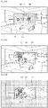
- FIG. 1a is a perspective view illustrating a head-mounted display device according to an embodiment of the present invention.
- a head-mounted display device 100 refers to a display device which is wearable on a user's head.
- a see-through display unit is positioned in a region adjacent to the user's head (e.g., eyes), and a speaker (not illustrated) is positioned in a region adjacent to the user's ears so that visual information and auditory information can be provided to the user.
- the head-mounted display device 100 includes an eyeglass type display device or a helmet type display device.
- the head-mounted display device 100 includes a monocular-type display device having a single display unit 190 that displays contents or a binocular-type display device having a plurality of display units 190 and 190a that may display a three-dimensional image.
- the binocular-type display device may selectively operate one of the plurality of display units 190 and 190a.
- the head-mounted display device 100 includes a first optical lens 10, a first housing 20 that accommodates a part of the first optical lens 10, a second housing 30 that includes a battery, a first housing connection portion 25 that connects the first housing 20 and the second housing 30.
- the head-mounted display device 100 includes a second optical lens 10a, a third housing 20a that accommodates a part of the second optical lens 10a, a fourth housing 30a that includes a battery, and a second housing connection portion 25a that connects the third housing 20a and the fourth housing 30a.
- the battery may be positioned in the first housing 20, the second housing 30, the third housing 20a, or the fourth housing 30a.
- the head-mounted display device 100 is mounted on the user's head by the elastically flexible first housing connection portion 25 and the second housing connection portion 25a.
- the head-mounted display device 100 includes a bridge 21 that connects the first housing 20 and the third housing 20a.
- the head-mounted display device 100 includes a light transmission unit 195 (see FIG. 1b ) if a single display unit 190 is included, or a plurality of light transmission units 195 if a plurality of display units 190 and 190a are included.
- the light transmission unit 195 is coupled to the rear surface of the second optical lens 10a using an optically clear adhesive.
- the light transmission unit 195 is coupled to the front surface of the first optical lens 10 and the second optical lens 10a, respectively, using an optically clear adhesive.
- the display unit 190 or 190a is positioned at a distance (e.g., not more than 5 cm) from at least one of the front surface of the first optical lens 10 or the second optical lens 10a, respectively, or positioned at a distance (e.g. not more than 5cm) from the rear surface of the first optical lens 10 or the second optical lens 10a, respectively.
- a distance e.g., not more than 5 cm
- the spacing between the display units 190 or 190a and the first optical lens 10 or the second optical lens 10a, respectively may be changed to correspond to a performance or a structure of the head-mounted display device 100.
- the head-mounted display device 100 includes a camera unit 150 (see FIG. 2 , where the camera unit 150 may include a first camera 151, a second camera 152, and a third camera not shown) and a sensor unit 170 (see FIG. 2 , where the sensor unit includes a plurality of sensors).
- the camera unit 150 is positioned in at least one of the first housing 20 and the third housing 20a.
- the camera unit 150 may be positioned in one of the first housing 20 and the third housing 20a or the first camera 151 of the camera unit 150 may be positioned in the first housing 20 and the second camera 152 of the camera unit 150 may be positioned in the third housing 20a.
- the third camera of the camera unit 150 may be positioned in the bridge 21.
- the sensor unit 170 is positioned in at least one of the first housing 20 and the third housing 20a.
- the sensor unit 170 may be positioned in one of the first housing 20 and the third housing 20a or the sensors of the sensor unit may be positioned in each of the first housing 20 and the third housing 20a. Further, a sensor of the sensor unit 170 may be positioned in the bridge 21.
- the first housing 20 of the head-mounted display device 100 includes at least one of a button 161 (see FIG. 2 ), a microphone 162 (see FIG. 2 ), a speaker 163 (see FIG. 2 ), a connector 164, and a touch pad 165 (see FIG. 2 ).
- the term "housing" in the present invention includes the first housing 20, the second housing 30, the third housing 20a, or the fourth housing 30a.
- FIG. 1a It may be easily understood by a person ordinarily skilled in the art that the positions of the constituent elements of the head-mounted display device 100 illustrated in FIG. 1a may be changed to correspond to the performance or structure of the head-mounted display device 100.
- FIG. 1b is a perspective view of a light transmission unit 195 of the head-mounted display device 100 according to an embodiment of the present invention.
- a light transmission unit 195 is coupled to the rear surface of the second optical lens 10a.
- a light transmission unit 195 may be coupled to the front surface of the second optical lens 10a.
- the light transmission unit 195 includes a first indium tin oxide layer 195a, an electrochromic layer 195b, an electrolyte layer 195c, a second indium tin oxide layer 195d, and electrodes 195e.
- each indium tin oxide layer will be referred to as an Indium Tin Oxide (ITO) layer.
- ITO layer may include an ITO film or an ITO glass.
- an ITO layer may be implemented using a silver nano wire, a copper mesh, a silver mesh, a silver salt, or silver nanoparticles which may replace the ITO.
- the light transmission unit 195 includes a first ITO layer 195a, an electrochromic layer 195b positioned on the ITO layer 195a and having a light transmittance which is changed to correspond to a supply voltage, an electrolyte layer 195c positioned on the electrochromic layer 195b, a second ITO layer 195d positioned on the electrolyte layer 195c, and electrodes 195e which are connected with the first ITO layer 195a and the second ITO layer 195d, respectively, and receives an input of the supply voltage.
- Each of the electrodes 195e is implemented as a transparent electrode. It may be easily understood by a person ordinarily skilled in the art that the position of each electrode 195e (e.g., a right upper end of the first ITO layer 195a or a left upper end of the second ITO layer 195d) may be changed to correspond to the performance or structure of the head-mounted display device 100.
- FIG. 2 is a schematic block diagram illustrating a head-mounted display device 100 according to an embodiment of the present invention.
- a head-mounted display device 100 is connected with an external device (not illustrated) wiredly or wirelessly using a mobile communication unit 120, a sub-communication unit 130, and a connector 164.
- the external device may include a portable phone (not illustrated) which includes a screen having an area wider than that of each of the plurality of display units 190 or 190a, a smart phone (not illustrated), a tablet Personal Computer (PC) (not illustrated), a Motion Picture Experts Group Audio Layer 3 (MP3) player, a video image player, a 3 Dimensional Television (3D-TV), a smart TV, an Light Emitting Diode (LED) TV, an Liquid Crystal Display (LCD) TV, or a server (not illustrated).
- the external device may include another head-mounted display device (not illustrated).
- the head-mounted display device 100 includes a device capable of transmitting/receiving data (e.g., an image, a text, a voice, or a video) with another connectable external device using a user input (or a user interaction, for example, a voice, a motion, a touch or a touch gesture) which is input via a head-mounted display device 100.
- data e.g., an image, a text, a voice, or a video
- a user input or a user interaction, for example, a voice, a motion, a touch or a touch gesture
- the head-mounted display device 100 includes a display unit 190 and a light transmission unit 195.
- the head-mounted display device 100 includes a control unit 110, a mobile communication unit 120, a sub-communication unit 130, a multimedia unit 140, a camera unit 150, a Global Positioning System (GPS) unit 155, an input/output unit 160, a sensor unit 170, a storage unit 175, and a power supply unit 180.
- GPS Global Positioning System
- the sub-communication unit 130 includes at least one of a wireless Local Area Network (LAN) unit 131 and a short-range communication unit 132, and the multimedia unit 140 includes at least one of an audio reproducing unit 141 and a video reproducing unit 142.
- the camera unit 150 includes at least one of a first camera 151 and a second camera 152, the input/output unit 160 includes at least one of a button 161, a microphone 162, a speaker 163, a connector 164, and a touch pad 165.
- the sensor unit 170 includes an illuminance sensor 171, a proximity sensor 172, and a gyro sensor 173.
- the control unit 110 includes a processor 111, a Read-Only Memory (ROM) 112 in which a control program for controlling the head-mounted display device 100 is stored, and an Random Access Memory (RAM) 113 which may be used as a region to store a signal or data input received by the head-mounted display device 100 or a storage region for various tasks performed by the head-mounted display device 100.
- ROM Read-Only Memory
- RAM Random Access Memory
- the control unit 110 controls overall action of the head-mounted display device 100 and signal flow between the elements 120 to 195 of the head-mounted display device 100, and processing data.
- the control unit 110 controls a power supply, from the power supply unit 180, to the elements 120 to 195.
- the control unit 110 executes an Operating System (OS) and various applications stored in the storage unit 175.
- OS Operating System
- the processor 111 includes a Graphics Processing Unit (GPU) (not illustrated) for graphic processing.
- the processor 111 may be implemented as a core (not illustrated) and the GPU (not illustrated) may be implemented as a System on Chip (SoC).
- SoC System on Chip
- the processor 111 may include a single core, dual cores, triple cores, quad cores, and cores of multiples thereof.
- the processor 111, the ROM 112, and the RAM 113 are interconnected via an internal bus.
- the control unit 110 controls the mobile communication unit 120, the sub-communication unit 130, the multimedia unit 140, the camera unit 150, the GPS unit 155, the input/output unit 160, the sensor unit 170, the storage unit 175, the power supply unit 180, the display unit 190, and the light transmission unit 195.
- control unit includes the processor 111, the ROM 112, and the RAM 113.
- the control unit 110 of an embodiment of the present invention detects an illuminance to determine an application to be displayed on the display unit 190 of the head-mounted display device 100, to determine a light transmittance corresponding with the illuminance and the application, and to change the light transmittance of the light transmission unit 195 of the head-mounted display device 100 to the determined light transmittance.
- the control unit 110 determines a supply voltage corresponding to the determined light transmittance, and supplies the determined supply voltage to the light transmission unit 195.
- the control unit 110 uses at least one of the illuminance detected via the sensor unit 170 and an illuminance received externally as the illuminance.
- the control unit 110 determines an application using at least one of information of the application and contents executed by the application.
- the control unit 110 uses at least one of a program manager that manages a life cycle of an application executed in the head-mounted display device 100 and an application specification file in which the application information is described in determining the application.
- the control unit 110 determines an application using an activity manager or a package manager as the program manager.
- the control unit 110 causes the determined light transmittance to be changed by a user input.
- the control unit 110 causes the visibility of the contents displayed on the display unit 190 to be changed by the light transmittance of the light transmission unit 195.
- the control unit 110 causes the determined light transmittance to be changed in a range from 5 % to 95 %.
- the control unit 110 provides at least an auditory feedback in response to a change of the light transmittance.
- an additional visual feedback can be provided.
- the control unit 110 detects the illuminance to determine the contents to be displayed on the display unit 190 of the head-mounted display device 100, and to change the light transmittance of the light transmission unit 195 of the head-mounted display device 100 according to the light transmittance determined according to the illuminance and the contents.
- the control unit 110 determines an application to be displayed on the display unit 190 of the head-mounted display device 100, and changes the light transmittance of the light transmission unit 195 of the head-mounted display device 100 according to the determined light transmittance to correspond to the application.
- the mobile communication unit 120 is connected with an external device wiredly or wirelessly using one or more antennas according to the control unit 110.
- the mobile communication unit 120 transmits/receives wireless signals for voice communication, video communication, Short Message Service (SMS), Multimedia Message Service (MMS), or data communication with a portable phone having a phone number connectable with the head-mounted display device 100, a smart phone (not illustrated), a tablet PC or another head-mounted display device (not illustrated).
- SMS Short Message Service
- MMS Multimedia Message Service
- the sub-communication unit 130 includes at least one of the wireless LAN unit 131, and the short-range communication unit 132.
- the sub-communication unit 130 may include only one of the wireless LAN unit 131 and the short-range communication unit 132 or both the wireless LAN unit 131 and the short-range communication unit 132.
- the wireless LAN unit 131 may be wirelessly connected to an Access Point (AP) in a place where the AP (not illustrated) is installed according to the control unit 110.
- the wireless LAN unit 131 supports the Wireless LAN Standards (IEEE802.11x) of the Institute of Electrical and Electronics Engineers (IEEE).
- the short-range communication unit 132 provides short-range communication between the head-mounted display device 100 and an external device wirelessly without the AP according to the control unit 110.
- the short-range communication unit 132 may include, for example, Bluetooth, Bluetooth Low Energy, Infra-red Data Association (IrDA), Wireless Fidelity (Wi-Fi), Ultra Wideband (UWB), and Near Field Communication (NFC).
- IrDA Infra-red Data Association
- Wi-Fi Wireless Fidelity
- UWB Ultra Wideband
- NFC Near Field Communication
- the head-mounted display device 100 includes, depending on its performance, at least one of the mobile communication unit 120, the wireless LAN unit 131, and the short-range communication unit 132.
- the head-mounted display device 100 includes one of the mobile communication unit 120, the wireless LAN unit 131, short-range communication unit 132, and a combination of the mobile communication unit 120, the wireless LAN unit 131, and the short-range communication unit 132.
- the term “communication unit” includes the mobile communication unit 120 and the sub-communication unit 130.
- the mobile communication unit 120 of an embodiment of the present invention connects the head-mounted display device 100 and an external device according to the control unit 110.
- the mobile communication unit 120 transmits data or contents to an external device according to the control unit 110.
- the mobile communication unit 120 transmits/receives data to/from an external device according to the control unit 110.
- the mobile communication unit 120 receives an illumination reception from an external device according to the control unit 110.
- the multimedia unit 140 includes the audio reproducing unit 141 or the video reproducing unit 142.
- the audio reproducing unit 141 reproduces an audio source previously stored in the storage unit 175 of the head-mounted display device 100 or received from an external source (for example, an audio file, of which the file extension is mp3, Windows Media Audio (wma), Operation Good Guys (ogg), or Waveform Audio File (wav)) using an audio compression/decompression (codec) unit according to the control unit 110.
- an audio file of which the file extension is mp3, Windows Media Audio (wma), Operation Good Guys (ogg), or Waveform Audio File (wav)
- codec audio compression/decompression
- the audio reproducing unit 141 reproduces an auditory feedback corresponding to a change of the light transmittance of the light transmission unit 195 (e.g., output of the audio source stored in the storage unit 175) using the audio codec unit according to the control unit 110.
- the video reproducing unit 142 reproduces a digital video source previously stored in the storage unit 175 of the head-mounted display device 100 or received from an external source (for example, a file, of which the file extension is Moving Picture Expert Group (mpeg or mpg), MPEG Audio Layer 4 (mp4), Audio Video Interleave (avi), Quick Time Movie (mov), Small Web Format (swf), Macromedia Flash (fla), or Matroska Video Format (mkv)) using a video codec unit according to the control unit 110.
- an external source for example, a file, of which the file extension is Moving Picture Expert Group (mpeg or mpg), MPEG Audio Layer 4 (mp4), Audio Video Interleave (avi), Quick Time Movie (mov), Small Web Format (swf), Macromedia Flash (fla), or Matroska Video Format (mkv)
- a video codec unit for example, a file, of which the file extension is Moving Picture Expert Group (mpeg or mpg), MPEG Audio Layer 4 (mp4),
- the video reproducing unit 142 reproduces a visual feedback corresponding to a change of the light transmittance of the light transmission unit 195 (for example, output of a video source stored in the storage unit 175) using the video codec unit according to the control unit 110.
- the audio reproducing unit 141 or the video reproducing unit 142 of the multimedia unit 140 may be included in the control unit 110.
- the term "video codec unit” in an embodiment of the present invention may include one or more video codec units.
- the term "audio codec unit” in an embodiment of the present invention includes one or more audio codec units.
- the camera unit 150 photographs a still image or a moving image in a user's line of sight according to the control unit 110.
- the camera unit 150 may be positioned in at least one of the bridge 21, the first housing 20, and the third housing 20a.
- the camera unit 150 may be positioned in one of the bridge 21, the first housing 20, and the third housing 20a; or the camera unit 150 may be positioned in two or more of the bridge 21, the first housing 20, and the third housing 20a.
- the head-mounted display device 100 includes the first camera 151.
- the head-mounted display device 100 includes the first camera 151 and the second camera 152.
- the head-mounted display device 100 may include a third camera (not illustrated) which may be positioned in one of the second housing 30 and the fourth housing 30a of the head-mounted display device 100 and is capable of photographing a still image or a moving image behind the user.
- the first camera 151 or the second camera 152 may include an auxiliary light source that provides an amount of light required for photographing (for example, a flash 153).
- the first camera 151 and the second camera 152 may photograph a three-dimensional still image or a three-dimensional moving image according to the control unit 110.
- one of the first camera 151 and the second camera 152 may take a photograph including wide angle photography, telephotography, and close-up photography using a separate adaptor (not illustrated).
- the camera unit 150 may photograph a still image or a moving image around the head-mounted display device 100 and transmit the still image or the moving image to the control unit 110.
- the control unit 110 transmits the received still image or moving image to an external device using the mobile communication unit 120.
- the control unit 110 calculates the illumination around the head-mounted display device 100 using the photographed still image or moving image.
- the GPS unit 155 periodically receives information (for example, correct position information or time information from a GPS satellite from which the head-mounted display device 100 is capable of receiving a signal) from a plurality of GPS satellites orbiting the earth.
- the head-mounted display device 100 determines the present position, moving speed, or time of the head-mounted display device 100 using the information received from the plurality of GPS satellites.
- the input/output unit 160 includes one or more buttons 161, one or more microphones 162, one or more speakers 163, one or more connectors 164, or one or more touch pads 165.
- the button 161 includes a power/lock button positioned on the first housing 20.
- the button 161 may include a home button on the first housing 20.
- the button 161 may be implemented not only as a physical button but also as a touch button on the housings of the head-mounted display device 100.
- the microphone 162 receives a voice or a sound external to the head-mounted display device 100 and generates an electrical signal according to the control unit 110.
- the electrical signal generated by the microphone 162 is converted in the audio codec unit and stored in the storage unit 175 or output via the speaker 163.
- One or more microphones 162 may be positioned in the first housing 20 and the third housing 20a of the head-mounted display device 100.
- one or more microphones 162 may be positioned in the second housing 30 and the fourth housing 30a of the head-mounted display device 100.
- the speaker 163 outputs sounds corresponding to various contents of the mobile communication unit 120, the sub-communication unit 130, the multimedia unit 140, the camera unit 150, or an application (for example, a wireless signal, a broadcast signal, an audio source, a video file, or a photograph) externally from the head-mounted display device 100, using the audio codec unit, according to the control unit 110.
- the speaker 163 outputs a sound corresponding to a function performed by the head-mounted display device 100 (for example, a touch operation sound corresponding to inputting a phone number, or taking a photograph).
- At least one speaker 163 may be positioned in the housing of the head-mounted display device 100. Referring to FIGs. 1 and 2 , the speaker 163 may be positioned in a region of the housing of the head-mounted display device 100 (for example, a region adjacent to a user's ear capable of receiving an output sound). In addition, the speaker 163 of the head-mounted display device 100 may include an air conduction speaker or a bone conduction speaker.
- the speaker 163 outputs an auditory feedback corresponding to a change of the light transmittance of the light transmission unit 195 according to the control unit 110.
- the connector 164 connects the head-mounted display device 100 to an external device or a power source.
- the head-mounted display device 100 transmits data stored in the storage unit 175 to an external device or receives data from the external device via a wired cable connected to the connector 164 according to the control unit 110.
- the head-mounted display device 100 receives power from a power source connected to the connector 164 via the wired cable, or a charge for a battery.
- the touch pad 165 receives a user input (for example, a touch or a touch and drag) to control the head-mounted display device 100.
- the touch pad 165 is planar (for example, a polygonal shape, a circular shape, an oval shape, or a rounded-rectangular shape) and incorporates a sensor.
- the touch pad 165 is positioned on a side surface of a housing of the head-mounted display device 100.
- the user input of the touch pad 165 is not limited to contact by the user's body or a touchable input unit (for example, a stylus pen) but includes non-contact (for example, hovering in which a detectable spacing between the touch pad 165 and the user's body or between the touch pad 165 and an input unit is 20 mm or less). It may be easily understood by a person ordinarily skilled in the art that the detectable non-contact spacing in the touch pad 165 may be changed depending on the performance or structure of the head-mounted display device 100.
- the head-mounted display device 100 may include one of a trackball and a pointing stick which is compatible with the touch pad 165.
- the sensor unit 170 includes at least one sensor which detects a condition of the head-mounted display device 100 or a peripheral condition.
- the sensor unit 170 is positioned on the front surface or a side surface of a housing of the head-mounted display device 100.
- the sensor unit 170 may include an illuminance sensor 171 which detects an amount of light around the head-mounted display device 100, a proximity sensor 172 which detects proximity of any other object in relation to the head-mounted display device 100, a gyro sensor 173 which detects a slope of the head-mounted display device 100 using rotational inertia of the head-mounted display device 100, an acceleration sensor which detects a moving condition of three axes (for example, x-axis, y-axis, and z-axis) applied to the head-mounted display device 100, a gravity sensor which detects an acting direction of gravity, or an altimeter which detects an altitude by measuring an atmospheric pressure.
- the illuminance sensor 171 detects an illuminance around the head-mounted display device 100.
- the illuminance sensor 171 transmits an illuminance signal corresponding to the detected illuminance to the control unit 110 according to the control unit 110.
- the plurality of sensors included in the sensor unit 170 may be implemented with separate Integrated Circuits (ICs or chips) or a single chip (for example, a six-axis sensor including a geomagnetic sensor and an acceleration sensor or a nine-axis sensor including a geomagnetic sensor, an accelerator sensor and a gyro sensor).
- ICs or chips Integrated Circuits
- a single chip for example, a six-axis sensor including a geomagnetic sensor and an acceleration sensor or a nine-axis sensor including a geomagnetic sensor, an accelerator sensor and a gyro sensor.
- the sensors of the sensor unit 170 may be added or omitted depending on the performance of the head-mounted display device 100.
- the storage unit 175 stores signals or data to be input/output in response to an operation of the mobile communication unit 120, the sub-communication unit 130, the multimedia unit 140, the camera unit 150, the GPS unit 155, the input/output unit 160, the sensor unit 170, the display unit 190, or the light transmission unit 195 according to the control unit 110.
- the storage unit 175 stores control programs for controlling the head-mounted display device 100 or the control unit 110, a Graphical User Interface (GUI) related to an application provided by a manufacture or downloaded from an external source, images for providing the GUI, user information, a document, data bases, or associated data.
- GUI Graphical User Interface
- the term, "storage unit” in the present invention includes the storage unit 175, a ROM 112 or a RAM 114 within the control unit, or a memory card which may be equipped in the head-mounted display device 100 (for example, a micro Secure Digital (SD) card, and a memory stick).
- the storage unit 175 may include a non-volatile memory, a volatile memory, a Hard Disc Drive (HDD), or a Solid State Drive (SSD).
- the storage unit 175, may store a command, a command list, notification, texts (for example, Yes and No), an icon, an object, an application screen, contents displayed on the application screen, screen data, or various sub-screens which are displayed on the display unit 190.
- the storage unit 175 may store illuminance information (for example, an identification ID for history management, an illuminance value, illuminance detecting time (for example, detecting time of the illuminance sensor 171 or receiving time for the communication unit)), or current position information (for example, an outdoor position by the GPS unit 155 or an indoor position by the mobile communication unit 120) which are received via the illuminance sensor 171 or the mobile communication unit 120.
- illuminance information for example, an identification ID for history management, an illuminance value, illuminance detecting time (for example, detecting time of the illuminance sensor 171 or receiving time for the communication unit)
- current position information for example, an outdoor position by the GPS unit 155 or an indoor position by the mobile communication unit 120
- the storage unit 175 may include first illumination information or second illuminance information.
- the storage unit 175 may store an application specification file (for example, when the OS is Android, the application specification file is a manifest file application (AndroidManifest.xml)) including various information items related to names and configurations of applications.
- the storage unit may store a program manager (for example, an activity manager or a package manager).
- the storage unit 175 may store a light transmittance table.
- the storage unit 175 may store a light transmittance table of an illuminance-application such as Table 1.
- the light transmittance table may be stored as a look-up table.
- the storage unit 175 may store an illuminance-light transmittance table (not illustrated). Further, the storage unit 175 may store an application-light transmittance table (not illustrated).
- Light transmittance information corresponding to a determined light transmittance may be stored in the storage unit 175.
- the light transmittance information may include an identification ID for history management, a determined light transmittance, an illuminance corresponding to the light transmittance, a determined application, a content (or a content category) executed in the application, or the like.
- the storage unit may store first light transmittance information, second light transmittance information, or third light transmittance information.
- the storage unit 175 may store a supply power table.
- the storage unit may store a light transmittance-supply power table such as Table 2.
- the supply power table may be stored as a look-up table.
- the storage unit 175 may store supply voltage information corresponding to a determined supply voltage.
- the supply voltage information may include an identification ID for history management, a determined supply voltage, a light transmittance corresponding to the supply voltage, illuminance, a determined application, a content (or a content category) executed in the application, or the like.
- the storage unit 175 may store a user input (for example, the user's voice which is received through, for example, the microphone 162, the user's motion which may be detected through, for example, the sensor 170, the user's touch which is received through, for example, the button 161, or the user's touch gesture which may be detected via the touch pad 165, for example, a touch, a flick or a swipe).
- a user input for example, the user's voice which is received through, for example, the microphone 162, the user's motion which may be detected through, for example, the sensor 170, the user's touch which is received through, for example, the button 161, or the user's touch gesture which may be detected via the touch pad 165, for example, a touch, a flick or a swipe).
- the storage unit 175 may store a visual feedback (for example, a video source) or an auditory feedback output from the speaker 163 to be recognized by the user, in response to a change of the light transmittance of the light transmission unit.
- a visual feedback for example, a video source
- an auditory feedback output from the speaker 163 to be recognized by the user in response to a change of the light transmittance of the light transmission unit.
- the power supply unit 180 supplies power to one or more batteries positioned within the head-mounted display device 100.
- the one or more batteries may be positioned in the second housing 30 and the fourth housing 30a.
- the power supply unit 180 may supply power input from an external power source via a wired cable connected to the connector 164 to the head-mounted display device 100 according to the control unit 110.
- the power supply unit 180 may supply power to the head-mounted display device 100 via a wireless charge method (for example, a magnetic resonance method, an electromagnetic wave method, or a magnetic induction method) according to the control unit 110.
- the display unit 190 may be a see-through display unit which may provide Graphical User Interfaces (GUIs) corresponding to various services (for example, video call, data transmission, still image photography, video image photography, or an executed application screen) to the user.
- GUIs Graphical User Interfaces
- the display unit 190 may supply a GUI corresponding to a user input which is input via the button 161, the microphone 162, the touch pad 165, or the sensor unit 170 to the user.
- the display unit 190 may include a micro-display and an optical system.
- the display unit 190 may project an image displayed on the micro-display (for example, an LCD or an Organic LED (OLED)) to the user's eyes via the optical system (for example, a free curved optical system), including a lens and a wave-guide.
- the micro-display for example, an LCD or an Organic LED (OLED)
- OLED Organic LED
- the micro-display may include a display panel of, for example, a Liquid Crystal Display (LCD) type, an Organic Light Emitted Diode (OLED), or an Active Matrix Organic Light Emitted Diode (AMOLED).
- LCD Liquid Crystal Display
- OLED Organic Light Emitted Diode
- AMOLED Active Matrix Organic Light Emitted Diode
- a monocular-type display device includes a single display unit 190 that displays contents.
- a binocular-type display device includes a plurality of display units 190 and 190a that may display a three-dimensional image.
- the light transmission unit 195 adjusts the light transmittance of the transmitted light in response to a supplied voltage or a supplied current.
- the light transmission unit 195 may be bonded to the front or rear surface of the optical lens 10 using an optically clear adhesive.
- the light transmission unit 195 may be bonded to the front surface of the optical system of the display unit 190 using the optically clear adhesive.
- the light transmittance of the light transmission unit 195 may be adjusted to be close to about 100% to transmit most of the light or to be close to about 0% to prevent the transmission of most of the light in response to the supply voltage (or supply current) supplied to the light transmission unit 195.
- the supply voltage may be adjusted such that the light transmittance of the light transmission unit 195 may have a value in a range from 0% to 100% according to the control unit 110. According to an embodiment of the present invention, the light transmittance may have a value in a range from 5% to 95% according to the control unit 110. According to an embodiment of the present invention, the light transmittance may have a value in a range from 10% to 80% according to the control unit 110. Some of the incident light may penetrate the light transmission unit 195 and the remainder may be reflected by the light transmission unit 195 depending on the light transmittance.
- the light transmission unit 195 may include an electrochromic unit, a suspended particle unit, a liquid crystal unit, a photochromic unit, or a thermochromic unit.
- the electrochromic unit changes the light transmittance using a phenomenon in which a color is reversibly changed depending on a direction of an electric field according to the supply voltage input thereto.
- the electrochromic unit includes a material having an optical characteristic which is reversibly changed by an electrochemical oxidation-reduction reaction (which is included in, for example, an electrochromic layer).
- the electrochromic unit produces a chemical change of the material, i.e. an oxidation or reduction reaction to change a light transmittance (or a light reflectance) by using the supply voltage (or current).
- the electrochromic material may include various organic materials, inorganic materials, or a combination of an organic material and an inorganic material, such as titanium dioxide (TiO 2 ), Indium Tin Oxide (ITO), which is largely used as a transparent electrode material, an alloy of magnesium and calcium, or an alloy of magnesium and titanium.
- TiO 2 titanium dioxide
- ITO Indium Tin Oxide
- the suspended particle unit has a structure in which a conductive film is arranged between two transparent plates (for example, ITO plates).
- the film contains fine dispersed and suspended particles which absorb light.
- the suspended particles absorb light and is seen as the color black.
- the suspended particles are aligned so as to transmit light.
- the supply voltage which is adjusted manually or automatically, adjusts the transmittance of transmitted light rapidly and accurately.
- the liquid crystal in the liquid crystal unit has both of fluidity of a liquid and a regular molecule arrangement like solid crystals.
- the arrangement of liquid crystal molecules is changed by the supply voltage, and when no supply voltage is input, the liquid crystal molecules are returned to the original state thereof due to an elastic restoring force.
- the liquid crystal unit changes the light transmittance (or light reflectance) using such an operating principle.
- the liquid crystal unit may additionally change the light transmittance (or light reflectance) via an alloy with a different metal.
- An electronic mirror (not illustrated) made of a combination of such compounds may be fabricated in various types, such as a thin film type, a film type, and a glass type.
- the photochromic unit changes light transmittance using a dye, of which a color is transformed by ultraviolet rays or electrically generated ultraviolet rays (for example, D-shine photochromic dye).
- a dye of which a color is transformed by ultraviolet rays or electrically generated ultraviolet rays (for example, D-shine photochromic dye).
- thermochromic unit changes light transmittance using a material, of which a color changes according to a temperature.
- At least one element may be added to the elements illustrated in the head-mounted display device 100 of FIG. 1 or at least one of the elements illustrated in the head-mounted display device 100 may be omitted, depending on the performances of the head-mounted display device 100.
- FIG. 3 is a flowchart illustrating a method of changing a light transmittance of a head-mounted display device 100 according to an embodiment of the present invention.
- FIGs. 4a to 4e are illustrations of a method of changing a light transmittance of a head-mounted display device 100 according to an embodiment of the present invention.
- step S301 an application is executed in step S301.
- the user may see a real-world view 300 (for example, an interior) via the head-mounted display device 100.
- the real-world view 300 is seen via the optical lens 10 and the light transmission unit 195.
- the display unit 190 is not operated since no power is supplied according to the control unit 110.
- the light transmission unit 195 is also not operated since no power is supplied according to the control unit 110.
- a home screen 310 is displayed on the display unit 190.
- the home screen 310 may display the user's position 311 (for example, Seoul), the time 312 (for example, 12:45), or the weather 313 (for example, an icon corresponding to it being sunny).
- the home screen 310 may display the user's position 311, the time 312, and the weather 313, selectively display a subset thereof, or none of them.
- the position 311, the time 312, and the weather 313 may be displayed as a text, an icon, or an image.
- the display device 100 Upon receiving a user input for operating the display unit 190, the display device 100 is operated according to the control unit 110.
- the user input may be detected via the user's voice (for example, a voice received via the microphone 162), the user's motion (for example, a motion which may be detected via the sensor unit 170), the user's touch (for example, a touch received via the button 161), or the user's touch gesture (for example, a touch, flick, or swipe which may be detected via the touch pad 165).
- the user's voice for example, a voice received via the microphone 162
- the user's motion for example, a motion which may be detected via the sensor unit 170
- the user's touch for example, a touch received via the button 161
- the user's touch gesture for example, a touch, flick, or swipe which may be detected via the touch pad 165.
- the home screen 310 is displayed to be distinct from the real-world view 300 according to the control unit 110.
- the control unit 110 may display the edge of the home screen 310 to be distinct from the real-world view 300 or display the brightness of the home screen 310 to be dark.
- the light transmission unit 195 is not operated according to the control unit 110.
- a screen of an executed application is displayed on the display unit 190.
- the control unit 110 displays a screen 320 of an application corresponding to a user input (for example, a screen of a movie application) on the display unit 190.
- Applications executable on the head-mounted display device 100 may include, for example, a movie application, a music application, a photo application, a gallery application, a web browser application, an e-book (e-book reader) application, a game application, an augmented reality application, a Social Network Service (SNS) application, a messenger application, and an object recognition application.
- the contents displayed on the application executed in the head-mounted display device 100 may include, for example, a movie, an image, a text, a web, music, or information.
- the content may mean a content category.
- One application may reproduce a dedicated content or various contents.
- the movie application may reproduce a content, such as a movie or music.
- the control unit 110 determines the order of priority. For example, when a movie application is determined, the control unit 110 may determine the movie as a preferentially executed content.
- the control unit 110 displays a content (for example, a movie 321) in the movie application displayed on the display unit 190.
- a content for example, a movie 321
- step S302 in FIG. 3 an illuminance is detected.
- the control unit 110 detects the illuminance around the head-mounted display device 100 using the illuminance sensor 171.
- the illuminance sensor 171 outputs an illuminance signal corresponding to the detected illuminance to the control unit 110 (for example, an analog illuminance sensor may output an analog signal and a digital illuminance sensor may output a digital signal).
- the control unit 110 calculates the illuminance using the received illuminance signal.
- the control unit 110 stores the calculated illuminance in the storage unit 175 as detected illuminance information.
- the calculated illuminance may have a value in a range from 0 to 700 lux.
- An illuminance of artificial lighting (for example, studio lighting) may be 1,000 lux, an outdoor illuminance in the daytime may be 10,000 to 25,000 lux, and an illuminance of outdoor direct sunlight may be 32,000 to 130,000 lux.
- An illuminance at sunrise or sunset may be 400 lux, and an luminance of a full moon adjacent to the equator may be 1 lux.
- the illuminance detected in FIG. 4c or in step S302 in FIG. 3 for example, is 300 lux.
- the calculated illuminance may be changed to correspond to the luminance range detected by the illuminance sensor 171.
- the calculated illuminance may be changed in correspondence with the accuracy of the light transmittance which may be changed by the light transmission unit 195 (for example, in correspondence with the light transmittance to three decimal places).
- the control unit 110 detects the illuminance around the head-mounted display device 100 using the camera unit 150.
- the control unit 110 calculates the illuminance using luminance information of image data received via an image sensor of the camera unit 150 (for example, a Charge-coupled Device (CCD) or a Complementary Metal Oxide Semiconductor (CMOS)) and a gain.
- the control unit 110 stores the calculated illuminance in the storage unit 175 as photographing illuminance information.
- the control unit 110 determines the light transmittance of the light transmission unit 195 using the stored photographing illuminance information.
- control unit 110 When the application is executed, the control unit 110 receives the illuminance information around the head-mounted display device 100 from an external device via the mobile communication unit 120. The control unit 110 stores the received illuminance in the storage unit 175 as received illuminance information.
- the illuminance information includes at least one of the detected illuminance information, the received illuminance information, and the photographing illuminance information.
- the illumination information may include one of the detected illuminance information, the received illuminance information, and the photographing illuminance information, or a combination of the detected illuminance information, the received illuminance information, and the photographing illuminance information.
- the control unit 110 determines the light transmittance of the light transmission unit 195 using the stored illuminance information (for example, the detected illuminance information, the received illuminance information, or the photographing illuminance information).
- the control unit 110 may preferentially use the detected illuminance information.
- the illuminance includes illuminance information.
- the detected illuminance may include the detected illuminance information.
- the received illuminance may include the received illuminance information.
- the photographing illuminance may include the photographing illuminance information.
- the stored illuminance information may include an identification ID for history management, an illuminance value, an illuminance detection time (for example, a detection time of the illuminance sensor 171, a signal reception time via the mobile communication unit 120, or a photographing time via the camera unit 150), or present position information (for example, an outdoor position by the GPS unit 155 or an indoor position by the mobile communication unit 120).
- an identification ID for history management for example, an illuminance value
- an illuminance detection time for example, a detection time of the illuminance sensor 171, a signal reception time via the mobile communication unit 120, or a photographing time via the camera unit 150
- present position information for example, an outdoor position by the GPS unit 155 or an indoor position by the mobile communication unit 120.
- Detected surrounding illuminances may include the detected illuminance via the illuminance sensor 171, the received illuminance via the mobile communication unit 120, and the photographing illuminance via the camera unit 150.
- a periodic time interval for example, 30 minutes
- a movement of the head-mounted display device 100 may be detected by a sensor (for example, a gyro sensor 173, a motion sensor, or a geomagnetic sensor), or when the display unit 190 is supplied with power to operate, the control unit 110 detects the surrounding illuminance.
- step S303 in FIG. 3 the executed application is determined.
- control unit 110 determines an application executed to correspond to the user input.
- the control unit 110 determines the application executed using an application specification file including various information items related to a name and a configuration of the application. It may be easily understood by a person ordinarily skilled in the art that the application specification file may be changed in terms of a file name or a file extension according to an Operating System (OS) installed in the head-mounted display device 100.
- OS Operating System
- a file stored in the storage unit for example, a manifest file
- a table for example, a light transmittance table
- information(for example, illuminance information) includes meanings of "to figure out, “to identify”, “to recognize”, “to read”, and “to decide”, and may be expressed using various terms.
- the application specification file includes a manifest file (AndroidManifest.xml).
- the manifest file defines a name, an icon, a version, authority, a service, an execution method of a corresponding application, or category information of the contents displayed on the executed application (for example, a movie, an image, a text, a web, a music, or information).
- the control unit 110 defines the content category information, such as "Intent.category information” or "'action/category information" of an "intent-filter” of the manifest file and defines the content which is being reproduced using a related Application Programming Interface (API).
- a movie category may correspond to a video application or a camera application.
- An image category may correspond to a gallery application.
- a music category may correspond to a music application.
- a web category may correspond to a web browser application.
- a text category may correspond to an e-book application.
- an information (info) category may correspond to a message application or an SNS application.
- control unit 110 determines the executed application using a program manager.
- the program manager manages a life cycle of the application (for example, execution and ending of the application).
- the program manager includes an application manager.
- control unit 110 determines the executed application using an extension of a content. For example, in a case of a content, of which the extension is mpg, the control unit 110 determines the executed application as the video application. In a case of a content, of which the extension is Joint Photographic Expert Group (jpg), the control unit 110 determines the executed application as the gallery application.
- extension is Joint Photographic Expert Group (jpg)
- control unit 110 detects the surrounding illuminance even after the executed application is determined in step S303 in FIG. 3 .
- the light transmittance is determined in step S304 in FIG. 3 .
- the control unit 110 determines the light transmittance of the light transmission unit 195 using an illuminance and an application.
- the control unit 110 determines the light transmittance of the light transmission unit 195 using at least one of an illumination and an application stored in the storage unit 175.
- the control unit 110 may determine the light transmittance using one of the illuminance and the application or both the illuminance and the application.
- control unit 110 determines the light transmittance of the light transmission unit 195 using at least one of an illuminance stored in the storage unit 175 or a content executed in the application.
- control unit 110 may determine the light transmittance using one of the illuminance and the content executed in the application or both of the illuminance and the content executed in the application.
- Table 1 stored in the storage unit 175 illustrates examples of light transmittances determined using an illuminance and an application (or content).
- Content refers to contents executable in an application (or a content category)
- Illuminance refers to a detected illuminance (or a received illuminance or a photographing illuminance).
- the control unit 110 may determine the corresponding light transmittance of the light transmission unit 195 with reference to Table 1 stored in the storage unit 175.
- the light transmission unit 195 may change the light transmittance in the range from 10% to 90% according to the control unit 110.
- the light transmission unit 195 may change the light transmittance in the range from 5% to 95%.
- step S304 in FIG. 3 when the detected illuminance is 300 lux and the determined application is the movie application (or an executed content is a movie), the control unit 110 determines the light transmittance as 50% per Table 1.
- the control unit 110 determines the light transmittance of the light transmission unit 195 using one of the illuminance, the determined application, and the content executed in the application. In such a case, the control unit 110 may use Table 1 or another dedicated table stored in the storage unit 175 separately from Table 1.
- the other dedicated tables stored in the storage unit 175 may include, for example, a light transmittance table corresponding to the illuminance of the light transmission unit 195, a light transmittance table of the light transmission unit 195 corresponding to the application, or a light transmittance table of the light transmission unit 195 corresponding to the content executed in the application.
- the control unit 110 determines different light transmittances of light transmission unit 195 to correspond to detected illuminances, respectively. In addition, when illuminances are determined, the control unit 110 determines different transmittances of the light transmission unit 195 to correspond to executed applications or the contents reproduced in the applications, respectively. Even if the light transmittances of the light transmission unit 195 are the same, at least one of the contents and the illuminances may be different.
- the control unit 110 stores first light transmittance information corresponding to the determined light transmittance in the storage unit 175.
- the first light transmittance information may include, for example, an identification ID for history management, a determined light transmittance, a luminance corresponding to the light transmittance, a determined application, or a content type executed in the application.
- step S305 in FIG. 3 a supply voltage is determined.
- the control unit 110 determines the supply voltage to be supplied to the light transmission unit 195 from the power supply unit 180 using Table 2 stored in the storage unit 175 to correspond to the determined light transmittance.
- Table 2 represents examples of supply voltages corresponding to light transmittances determined according to an illuminance and an application.
- the supply voltage may be linearly changed from -1.85V to 0.6V depending on the light transmittance in percent (%), where the first column corresponds to the second column and the third column corresponds to the fourth column.
- the control unit 110 may determine a supply voltage corresponding to the light transmittance of 50% as -0.55V.
- the control unit 110 determines the supply voltage using interpolation for a light transmittance which is not indicated in Table 2.
- the supply voltages of Table 2 are those in a state where a residual capacity of the power supply unit 180 or a battery of the head-mounted display device 100 is normal. When the residual capacity of the battery of the head-mounted display device 100 is insufficient (for example, in a low-battery state), the control unit 110 determines a supply voltage which is different from that in Table 2 to correspond to the determined light transmittance.
- the control unit 110 stores supply voltage information corresponding to the determined supply voltage in the storage unit 175.
- the supply voltage information may include, for example, an identification ID for history management, a determined supply voltage, a light transmittance corresponding to the supply voltage, an illuminance, a determined application, or a content executed in the application.
- the supply voltages in Table 2 may be changed to correspond to the performances and structure of the head-mounted display device 100.
- the supply voltages in Table 2 may be converted to supply currents.
- step S306 in FIG. 3 the light transmittance of the light transmission unit is changed.
- the control unit 110 changes the light transmittance of the light transmission unit 195.
- the control unit 110 changes the supply voltage to correspond to the determined light transmittance supplied to the light transmission unit 195.
- the real-world view 300 of FIG. 4c is changed to another rear-world view 300a in FIG. 4d to correspond to the changed light transmittance (for example, 50%) of the light transmission unit 195.
- the user may watch both of the another real-world view 300a and the movie 321 displayed on the display unit 190.
- the user is provided with improved visibility of the movie 321 displayed on the display unit 190 because of the another real-world view 300a. Further, the user may become more absorbed in the displayed movie 321 because of the another real-world view 300a.
- the control unit 110 provides various feedback in response to a change of the light transmittance of the light transmission unit 195.
- the feedback is provided as an auditory feedback and may additionally be provided as a visual feedback.
- the control unit 110 may provide both the visual feedback and the auditory feedback in response to a change of the light transmittance.
- the control unit 110 if the head-mounted display device 100 includes a vibration motor, the control unit 110 provides a tactile feedback to the user using the vibration motor.
- a visual effect in response to a change of the light transmittance of the light transmission unit 195 (for example, an effect of changing the light transmittance to be visually different from the current light transmittance according to the determined light transmittance) is provided by the light transmission unit 195.
- another visual effect for example, an animation effect such as a separate image or fading applied to the non-illustrated separate image
- the above-described visual effects in response to a change of the light transmittance of the light transmission unit 195 may be provided by both the light transmission unit 195 and the display unit 190.
- the auditory feedback may output a sound in response to a change of the light transmittance of the light transmission unit 195 through the speaker 163.
- At least one feedback may be maintained from the start of a change of the light transmittance of the light transmission unit 195 to the completion of a change of the light transmittance.
- a feedback corresponding to a change of the light transmittance of the light transmission unit 195 (for example, at least one of the visual feedback and the auditory feedback) may be selected and/or changed through the configuration of the OS.
- the control unit 110 sets and/or changes a length of time in which at least one feedback corresponding to a change of the light transmittance of the light transmission unit 195 is provided to the user (for example, 500 msec) by a user input.
- step S307 in FIG. 3 the changed light transmittance is set.
- the control unit 110 displays a popup 330 and/or a pointer 331 for setting a changed light transmittance on the display unit 190.
- the popup 330 and/or the pointer 331 is displayed on the reproduced movie 321 to be distinctive from the movie 321.
- the pointer 331 may be positioned at "Yes” 332 as a default value. "Yes” 332 or “No” 331 may be input by a user input.
- the control unit 110 sets the changed light transmittance.
- step S308 in FIG. 3 the changed light transmittance is stored.
- the control unit 110 stores a second light transmittance information corresponding to the set light transmittance in the storage unit 175.
- the second light transmittance information may include an indication ID for history management, the set light transmittance, a luminance corresponding to the light transmittance, a determined application, or a content executed in the application.
- step S308 in FIG. 3 the method of changing the light transmittance of the head-mounted display device 100 ends.
- the method of changing the light transmittance of the head-mounted display device 100 may be ended when the light transmittance changed in step S308 in FIG. 3 is directly stored, skipping step S307 in FIG. 3 without setting the light transmittance changed by the user input in step S307 in FIG. 3 .
- step S307 in FIG. 3 when a changed light transmittance is not set, the process proceeds to step S309 in FIG. 3 .
- step S309 in FIG. 3 the light transmittance is changed manually.
- the control unit 110 allows the light transmittance determined in step S304 in FIG. 3 to be manually changed by user input.
- the user input which may manually change the light transmittance may include the user's voice (for example, a voice received through the microphone 162), the user's motion (for example, a motion detected through the sensor unit 170), the user's touch (for example, a touch received through the button 161), or the user's touch gesture (for example, a touch, flick or swipe detected through the touch pad 165).
- the control unit 110 changes the light transmittance of the light transmission unit 195 (for example, an automatically determined light transmittance) separately from the movie displayed on the display unit 190, in response to a user input.
- the present light transmittance (for example, 50%) may be increased (for example, to 51% or more) or decreased (for example, to 49% or less) by the control unit 110 based on the user input.
- the control unit 110 determines the supply voltage corresponding to the manually determined light transmittance using Table 2.
- the power supply unit 180 supplies the supply voltage corresponding to the manually determined light transmittance to the light transmission unit 195 according to the control unit 110.
- step S309 in FIG. 3 When the light transmittance is manually changed in step S309 in FIG. 3 , the process proceeds to step S308 in FIG. 3 .
- step S308 in FIG. 3 the changed light transmittance is stored.
- the control unit 110 may store a third light transmittance information corresponding to the manually set light transmittance in the storage unit 175.
- the third light transmittance information may include an identification ID for history management, the set light transmittance, a luminance corresponding to the light transmittance, a determined application, or a content executed in the application.
- step S308 in FIG. 3 the method of changing the light transmittance of the head-mounted display device 100 ends.
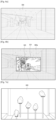
- FIGs. 5a and 5b are illustrations of a method of changing a light transmittance of the head-mounted display device, according to an embodiment of the present invention.
- FIGs. 5a and 5b illustrates a case in which detected illuminances are different from each other and determined applications are equal to each other, unlike FIGs. 4a to 4e .
- the user may watch a real-world view 400 (for example, an outdoor sports stadium) through the head-mounted display device 100.
- a real-world view 400 for example, an outdoor sports stadium
- the control unit 110 detects an illuminance. Since it is outdoor and daylight, the detected illuminance may be 700 lux.
- the control unit 110 determines an executed application 420 as a movie application (or a content executed as movie 421).
- the control unit 110 may determine the light transmittance corresponding to the detected illuminance and the determined application (or the movie as the content executed therein) to be 10% using Table 1.
- the control unit determines the supply voltage corresponding to the determined light transmittance of 10% to be 0.45 volts using Table 2.
- the control unit 110 changes the light transmittance of the light transmission unit 195.
- the power supply unit 180 supplies the determined supply voltage of 0.45 volts to the light transmission unit 195 according to the control unit 110.
- the real-world view 400 of FIG. 5a is changed to another real-world view 400a in FIG. 5b to correspond to the changed light transmittance (for example, 10%) of the light transmission unit 195.
- the user may watch both the another real-world view 400a and the movie 421 displayed on the display unit 190.
- the user is provided with improved visibility of the movie 421 displayed on the display unit 190 because of the another real-world view 400a.
- the user may become more adsorbed in the displayed movie due to the another real-world view 400a.
- FIGs. 6a and 6b are illustrations of a method of changing the light transmittance of the head-mounted display device 100, according to an embodiment of the present invention.
- FIGs. 6a and 6b illustrate a case in which detected illuminances are different from each other and determined applications are equal to each other, unlike FIGs. 4a to 4e .
- the user may watch a real-world view 500 (for example, an indoor dark hallway) through the head-mounted display device 100.
- a real-world view 500 for example, an indoor dark hallway
- the control unit 110 detects an illuminance. Since it is indoor and dark, the detected illuminance may be 100 lux.
- the control unit 110 determines an executed application 520 as a movie application (or a content executed therein as a movie 521).
- the control unit 110 may determine the light transmittance corresponding to the detected illuminance and the determined application (or the movie as the content executed therein) as 70% using Table 1.
- the control unit 110 determines the supply voltage corresponding to the determined light transmittance of 70% as -1.0 volts using Table 2.
- the control unit 110 changes the light transmittance of the light transmission unit 195.
- the power supply unit 180 supplies the determined supply voltage of -1.0 volts to the light transmission unit 195 according to the control unit 110.
- the real-world view 500 is changed to another real-world view 500a to correspond to the changed light transmittance (for example, 70%) of the light transmission unit 195.
- the user may watch both the another real-world view 500a and the movie 521 displayed on the display unit 190.
- the user is provided with improved visibility of the movie 521 displayed on the display unit 190 because of the another real-world view 500a. Further, the user may become more absorbed in the displayed movie because of the another real-world view 500a.
- FIGs. 7a and 7b are illustrations of a method of changing the light transmittance of the head-mounted display device 100, according to an embodiment of the present invention.
- FIGs. 7a and 7b illustrate a case in which detected illuminances are equal to each other and determined applications are different from each other, unlike FIGs. 4a to 4e .
- the user may watch a real-world view 600 (for example, indoor relics) through the head-mounted display device 100.
- a real-world view 600 for example, indoor relics
- the control unit 110 detects an illuminance. Since it is indoor and bright, the detected illuminance may be 300 lux.
- the control unit 110 may determine an executed application 620 as an object recognition application (or a content executed therein as information 621). The control unit 110 may determine the light transmittance corresponding to the detected illuminance and the determined application (or the information as the content executed therein) as 50% using Table 1. In addition, the control unit 110 determines the supply voltage corresponding to the determined light transmittance of 50% as -0.55 volts using Table 2.
- the control unit 110 changes the light transmittance of the light transmission unit 195.
- the power supply unit 180 supplies the determined supply voltage of -0.55 volts to the light transmission unit 195 according to the control unit 110.
- the real-world view 600 is changed to another real-world view 600a to correspond to the changed light transmittance (for example, 50%) of the light transmission unit 195.
- the user may watch both the another real-world view 600a and the information displayed on the display unit 190. The user is provided with improved visibility of the information displayed on the display unit 190 because of the another real-world view 600a.
- FIGs. 8a and 8b are illustrations of a method of changing the light transmittance of the head-mounted display device 100, according to an embodiment of the present invention.
- FIGs. 8a and 8b illustrate a case in which detected illuminances are different from each other and determined applications are also different from each other, unlike FIGs. 4a to 4e .
- the user may watch a real-world view 700 (for example, indoor relics) through the head-mounted display device 100.
- a real-world view 700 for example, indoor relics
- the control unit 110 detects an illuminance. Since it is indoor and darker than FIG. 7a , and the distance between the user and the relics are longer than that in FIG. 7a , the detected illuminance may be 100 lux.
- the control unit 110 may determine an executed application 720 as an object recognition application (or a content executed therein as information 721). The control unit 110 may determine the light transmittance corresponding to the detected illuminance and the determined application (or the information as the content executed therein) as 70% using Table 1. In addition, the control unit 110 determines the supply voltage corresponding to the determined light transmittance of 70% as -1.0 volts using Table 2.
- the control unit 110 changes the light transmittance of the light transmission unit 195.
- the power supply unit 180 supplies the determined supply voltage of -1.0 volts to the light transmission unit 195 according to the control unit 110.
- the real-world view 700 is changed to another real-world view 700a to correspond to the changed light transmittance (for example, 70%) of the light transmission unit 195.
- the user may watch both the another real-world view 700a and the information displayed on the display unit 190. The user is provided with improved visibility of the information displayed on the display unit 190 because of the another real-world view 700a.
- the methods according to embodiments of the present invention may be implemented in a form of program commands executed through various computer means to be recorded in a non-transitory computer-readable medium.
- the non-transitory computer-readable medium may include a program command, a data file, and a data structure individually or a combination thereof.
- Software may be stored, for example, in a volatile or non-volatile storage device such as a ROM, a memory such as a RAM, a memory chip, a memory device, or a memory IC, or a storage medium that is optically or magnetically recordable and simultaneously machine (for example, a computer) readable, such as a Compact Disc (CD), a Digital Video Disc (DVD), a magnetic disk, or a magnetic tape, regardless of its ability to be erased or re-recorded.
- a memory which may be included in the head-mounted display device corresponds to an example of the storage medium suitable for storing a program or programs including instructions by which the embodiments of the present invention are realized.
- the program command recorded in the medium is specially designed and configured for the present invention, but may be used after being known to those skilled in computer software fields.
Landscapes
- Physics & Mathematics (AREA)
- General Physics & Mathematics (AREA)
- Optics & Photonics (AREA)
- Engineering & Computer Science (AREA)
- Computer Hardware Design (AREA)
- Theoretical Computer Science (AREA)
- Controls And Circuits For Display Device (AREA)
- Control Of Indicators Other Than Cathode Ray Tubes (AREA)
- Nonlinear Science (AREA)
Claims (12)
- Verfahren zum Ändern der Lichtdurchlässigkeit einer kopfgetragenen Anzeige, HMD, die eine Anzeige und eine optische Linse enthält, wobei das Verfahren umfasst:Ermitteln (S302) einer ersten Beleuchtungsstärke um die HMD-Einheit herum;Bestimmen (S303) einer auf der Anzeige der HMD-Einheit anzuzeigenden Anwendung;Bestimmen (S304) einer ersten Lichtdurchlässigkeit zum Blockieren von Licht, das von außerhalb der optischen Linse übertragen wird, auf Grundlage der ersten Beleuchtungsstärke und einem Typ der Anwendung;Bestimmen (S305) einer Versorgungsspannung, die der ersten Lichtdurchlässigkeit entspricht, wobei die Versorgungsspannung auf Grundlage eines Zustands einer Batterie der HMD-Einheit und der ersten Beleuchtungsstärke bestimmt wird;Einstellen (S306) einer Lichtdurchlässigkeit der optischen Linse durch Verwenden der Versorgungsspannung; undAnzeigen von in der Anwendung enthaltenen Inhalten auf der Anzeige, nachdem die Lichtdurchlässigkeit der optischen Linse auf die eingestellte Lichtdurchlässigkeit geändert wurde,wobei, wenn die erste Beleuchtungsstärke höher als eine zweite Beleuchtungsstärke ist, die erste Lichtdurchlässigkeit niedriger als eine zweite Lichtdurchlässigkeit zum Blockieren von Licht ist, das von außerhalb der optischen Linse durchgelassen wird, die auf Grundlage der zweiten Beleuchtungsstärke und der Art der Anwendung bestimmt werden würde,wobei die Anwendung eine von einer Filmanwendung, einer Bildanwendung, einer Textanwendung und einer Webanwendung enthält, undwobei das Verfahren ferner das Bereitstellen einer akustischen Rückmeldung über ein Audiowiedergabeteil der HMD-Einheit umfasst, um die Einstellung der Lichtdurchlässigkeit der optischen Linse anzuzeigen.
- Verfahren nach Anspruch 1, ferner umfassend:
wobei die Versorgungsspannung an ein in der HMD-Einheit enthaltenes Lichtdurchlässigkeitsteil geliefert wird. - Verfahren nach Anspruch 1, wobei das Bestimmen der ersten Lichtdurchlässigkeit das Bestimmen (S304) der ersten Lichtdurchlässigkeit ferner auf Grundlage von Informationen über die Anwendung enthält.
- Verfahren nach Anspruch 1, wobei das Bestimmen (S304) der ersten Lichtdurchlässigkeit das Bestimmen der ersten Lichtdurchlässigkeit ferner auf Grundlage von mindestens einem Programmverwalter enthält, der einen Lebenszyklus der auf der kopfgetragenen Anzeige angezeigten Anwendung verwaltet, und einer Anwendungsspezifikationsdatei, die die Anwendungsinformationen beschreibt.
- Verfahren nach Anspruch 4, wobei der Programmverwalter einen Aktivitätenverwalter oder einen Paketverwalter enthält.
- Verfahren nach Anspruch 1, wobei die erste Lichtdurchlässigkeit durch eine Benutzereingabe veränderbar ist.
- Verfahren nach Anspruch 1, ferner umfassend das Ändern (S306) einer Sichtbarkeit des in der Anwendung enthaltenen Inhalts auf eine erste Sichtbarkeit, die der ersten Lichtdurchlässigkeit entspricht.
- Verfahren nach Anspruch 1, wobei die erste Lichtdurchlässigkeit in einem Bereich von 5 % bis 95 % veränderbar ist.
- Verfahren nach Anspruch 2, wobei das Lichtdurchlässigkeitsteil eines der Elemente eines elektrochromen Teils, eines Schwebstoffteils, eines Flüssigkristallteils, eines photochromen Teils oder eines thermochromen Teils enthält.
- Kopfgetragene Anzeige (100), umfassend:ein Lichtdurchlässigkeitsteil (195), das konfiguriert ist, um die Lichtdurchlässigkeit einer optischen Linse zu ändern, die in der kopfgetragenen Anzeige, HMD-Einheit (100) enthalten ist;eine Anzeige (190), die konfiguriert ist, um einen Bildschirm einer Anwendung vor einem Teil der optischen Linse anzuzeigen; ein Audiowiedergabeteil (141); undeine Steuerung (110), die konfiguriert ist, um:eine erste Beleuchtungsstärke um die HMD-Einheit (100) zu ermitteln,die auf der Anzeige (190) anzuzeigende Anwendung zu bestimmen,eine erste Lichtdurchlässigkeit zum Blockieren von Licht zu bestimmen, das von außerhalb der optischen Linse übertragen wird, auf Grundlage der ersten Beleuchtungsstärke und einem Typ der Anwendung,eine Versorgungsspannung zu bestimmen (S305), die dem ersten Lichtdurchlässigkeitsgrad entspricht, wobei die Versorgungsspannung auf Grundlage eines Zustands einer Batterie der HMD-Einheit und der ersten Beleuchtungsstärke bestimmt wird;die Lichtdurchlässigkeit der optischen Linse unter Verwendung der Versorgungsspannung einstellen, undin der Anwendung enthaltene Inhalte auf der Anzeige (190) nach dem Ändern der Lichtdurchlässigkeit der optischen Linse auf die eingestellte Lichtdurchlässigkeit anzeigen,wobei, wenn die erste Beleuchtungsstärke höher als eine zweite Beleuchtungsstärke ist, die erste Lichtdurchlässigkeit niedriger als eine zweite Lichtdurchlässigkeit zum Blockieren von Licht ist, das von außerhalb der optischen Linse durchgelassen wird, die auf Grundlage der zweiten Beleuchtungsstärke und der Art der Anwendung bestimmt werden würde,wobei die Anwendung eine von einer Filmanwendung, einer Bildanwendung, einer Textanwendung und einer Webanwendung enthält, undwobei die Steuerung (110) ferner konfiguriert ist, um der HMD-Einheit eine akustische Rückmeldung über das Audiowiedergabeteil (141) bereitzustellen, um das Einstellen der Lichtdurchlässigkeit der optischen Linse anzuzeigen.
- Kopfgetragene Anzeige (100) nach Anspruch 10, wobei die Steuerung (110) konfiguriert ist, um die der ersten Lichtdurchlässigkeit entsprechende Versorgungsspannung von einem Stromversorgungsteil (180) an das Lichtdurchlässigkeitsteil (195) zu liefern.
- Kopfgetragene Anzeige (100) nach Anspruch 10, wobei das Lichtdurchlässigkeitsteil (195) ein elektrochromes Teil, ein Schwebstoffteil, ein Flüssigkristallteil, ein photochromes Teil und ein thermochromes Teil enthält.
Applications Claiming Priority (2)
| Application Number | Priority Date | Filing Date | Title |
|---|---|---|---|
| KR1020130140188A KR102153599B1 (ko) | 2013-11-18 | 2013-11-18 | 머리 착용형 디스플레이 장치 및 머리 착용형 디스플레이 장치의 광 투과율 변경 방법 |
| PCT/KR2014/009725 WO2015072669A1 (en) | 2013-11-18 | 2014-10-16 | Head-mounted display device and method of changing light transmittance of the same |
Publications (3)
| Publication Number | Publication Date |
|---|---|
| EP3072008A1 EP3072008A1 (de) | 2016-09-28 |
| EP3072008A4 EP3072008A4 (de) | 2017-07-12 |
| EP3072008B1 true EP3072008B1 (de) | 2023-02-15 |
Family
ID=53057576
Family Applications (1)
| Application Number | Title | Priority Date | Filing Date |
|---|---|---|---|
| EP14862789.6A Active EP3072008B1 (de) | 2013-11-18 | 2014-10-16 | Kopfmontierte anzeigevorrichtung und verfahren zum wechseln von deren lichtdurchlässigkeit |
Country Status (5)
| Country | Link |
|---|---|
| US (3) | US9898995B2 (de) |
| EP (1) | EP3072008B1 (de) |
| KR (1) | KR102153599B1 (de) |
| CN (2) | CN105849622B (de) |
| WO (1) | WO2015072669A1 (de) |
Families Citing this family (42)
| Publication number | Priority date | Publication date | Assignee | Title |
|---|---|---|---|---|
| US9417660B2 (en) * | 2012-04-25 | 2016-08-16 | Kopin Corporation | Collapsible head set computer |
| KR102153599B1 (ko) * | 2013-11-18 | 2020-09-08 | 삼성전자주식회사 | 머리 착용형 디스플레이 장치 및 머리 착용형 디스플레이 장치의 광 투과율 변경 방법 |
| US9995933B2 (en) * | 2014-06-24 | 2018-06-12 | Microsoft Technology Licensing, Llc | Display devices with transmittance compensation mask |
| US10663832B1 (en) * | 2015-08-07 | 2020-05-26 | Kinestral Technologies, Inc. | Indicator for windows |
| KR102690986B1 (ko) | 2016-03-23 | 2024-08-02 | 삼성디스플레이 주식회사 | 헤드 마운트 장치 및 표시 장치 |
| JP2017198825A (ja) * | 2016-04-27 | 2017-11-02 | 株式会社リコー | 単眼型画像表示装置 |
| JP6736962B2 (ja) * | 2016-05-11 | 2020-08-05 | 富士通株式会社 | 画像送信制御プログラム、画像送信制御方法および画像送信制御装置 |
| CN107919096A (zh) * | 2016-10-11 | 2018-04-17 | 中兴通讯股份有限公司 | 一种控制方法和头戴式设备 |
| US10848899B2 (en) * | 2016-10-13 | 2020-11-24 | Philip Scott Lyren | Binaural sound in visual entertainment media |
| KR102630001B1 (ko) * | 2016-10-31 | 2024-01-25 | 엘지디스플레이 주식회사 | 유기발광 표시장치, 그를 포함한 헤드 장착형 디스플레이, 및 그의 제조방법 |
| GB2555602B (en) * | 2016-11-02 | 2020-02-12 | Swimar Ltd | Heads-up display for eyewear |
| KR102675011B1 (ko) | 2016-11-28 | 2024-06-17 | 삼성디스플레이 주식회사 | 표시장치 |
| JP2018137505A (ja) * | 2017-02-20 | 2018-08-30 | セイコーエプソン株式会社 | 表示装置およびその制御方法 |
| US10699691B1 (en) * | 2017-06-29 | 2020-06-30 | Amazon Technologies, Inc. | Active noise cancellation for bone conduction speaker of a head-mounted wearable device |
| CN109426091B (zh) * | 2017-08-31 | 2021-01-29 | 京东方科技集团股份有限公司 | 曝光装置、曝光方法及光刻方法 |
| KR101986192B1 (ko) * | 2017-11-29 | 2019-06-05 | 주식회사 스포컴 | 광 투과율을 조절할 수 있는 아이웨어 |
| US11921289B2 (en) | 2017-12-20 | 2024-03-05 | Vuzix Corporation | Augmented reality display system |
| EP3521910B1 (de) * | 2018-02-06 | 2024-07-03 | Essilor International | Vorrichtung mit variabler optischer transmission und zugehöriges steuerungsverfahren |
| US11543659B2 (en) | 2018-02-09 | 2023-01-03 | Vuzix Corporation | Image light guide with circular polarizer |
| US10845600B2 (en) | 2018-04-24 | 2020-11-24 | Samsung Electronics Co., Ltd. | Controllable modifiable shader layer for head mountable display |
| US11119321B2 (en) | 2018-09-10 | 2021-09-14 | Apple Inc. | Electronic device with a display attached to a lens element |
| KR20200032467A (ko) * | 2018-09-18 | 2020-03-26 | 삼성전자주식회사 | 외부 광의 투과율을 조절할 수 있는 광학 부재를 포함하는 전자 장치 및 그의 동작 방법 |
| KR102328618B1 (ko) | 2018-12-19 | 2021-11-18 | 한국광기술원 | 반응형 광 감쇄장치 및 방법 |
| CN111522166B (zh) * | 2019-02-01 | 2024-09-27 | 松下知识产权经营株式会社 | 显示装置 |
| JP2020187287A (ja) * | 2019-05-16 | 2020-11-19 | ソニー株式会社 | 光透過型表示装置、調光方法、及びプログラム |
| CN110262039A (zh) * | 2019-06-26 | 2019-09-20 | Oppo广东移动通信有限公司 | 头戴式显示设备 |
| CN110286538B (zh) * | 2019-06-28 | 2022-05-24 | Oppo广东移动通信有限公司 | 显示方法、显示装置、头戴式显示装置和存储介质 |
| CN110361866A (zh) * | 2019-07-11 | 2019-10-22 | Oppo广东移动通信有限公司 | 一种透射光强可调的头戴显示设备 |
| CN110493729B (zh) * | 2019-08-19 | 2020-11-06 | 芋头科技(杭州)有限公司 | 增强现实设备的交互方法、设备及存储介质 |
| EP4089667A4 (de) * | 2020-01-09 | 2024-01-24 | Sony Interactive Entertainment Inc. | Anzeigesteuerungsvorrichtung, kopfmontierte anzeige und bildanzeigeverfahren |
| US11929006B2 (en) * | 2020-01-22 | 2024-03-12 | Sony Group Corporation | Display device |
| EP4172689B1 (de) * | 2020-06-26 | 2025-12-10 | Essilor International | Brillenvorrichtung und verfahren zum antrieb einer ophthalmischen linse mit variabler transmission |
| CN116601542A (zh) | 2020-09-21 | 2023-08-15 | 苹果公司 | 图像捕获和可见光透射的同步 |
| CN114371555A (zh) * | 2020-10-14 | 2022-04-19 | Oppo广东移动通信有限公司 | 穿戴式电子设备 |
| KR20220091160A (ko) | 2020-12-23 | 2022-06-30 | 삼성전자주식회사 | 증강 현실 디바이스 및 그 동작 방법 |
| US11682880B2 (en) * | 2021-04-23 | 2023-06-20 | Google Llc | Techniques for dynamic voltage control for laser diodes in head-wearable display devices |
| US12016420B2 (en) | 2021-04-30 | 2024-06-25 | Rockwell Collins, Inc. | Combined fast-switch tintable visor |
| KR102563076B1 (ko) * | 2021-06-11 | 2023-08-02 | 금오공과대학교 산학협력단 | 증강현실과 가상현실을 선택적으로 사용할 수 있는 하이브리드 영상출력 장치 |
| US12481199B2 (en) | 2021-09-27 | 2025-11-25 | Samsung Electronics Co., Ltd. | Electronic device for adjusting light transmittance of tintable lens and method for controlling the same |
| US12125156B2 (en) | 2021-12-17 | 2024-10-22 | Hcl Technologies Limited | Method and system for evaluating luminance in augmented reality (AR) applications |
| KR102746396B1 (ko) * | 2022-06-13 | 2024-12-23 | 에스케이씨 주식회사 | 전기변색소자 구동 제어 장치 및 방법 |
| CN120188087A (zh) * | 2022-11-03 | 2025-06-20 | 三星电子株式会社 | 根据外部光源的照度调节透光率的可穿戴设备及其控制方法 |
Citations (1)
| Publication number | Priority date | Publication date | Assignee | Title |
|---|---|---|---|---|
| US20130147859A1 (en) * | 2011-12-12 | 2013-06-13 | Seiko Epson Corporation | Transmission type display device, display method and display program |
Family Cites Families (19)
| Publication number | Priority date | Publication date | Assignee | Title |
|---|---|---|---|---|
| US5361359A (en) * | 1992-08-31 | 1994-11-01 | Trusted Information Systems, Inc. | System and method for controlling the use of a computer |
| TW579289B (en) * | 2001-05-23 | 2004-03-11 | Toshiba Tec Kk | Vacuum cleaner |
| US20050207314A1 (en) * | 2004-03-16 | 2005-09-22 | Matsushita Electric Industrial Co., Ltd. | Optical element, optical head, optical information device and method of controlling optical head |
| JP3957730B2 (ja) | 2005-06-02 | 2007-08-15 | シャープ株式会社 | 画像表示装置 |
| KR101367958B1 (ko) | 2007-12-18 | 2014-02-26 | 삼성전자주식회사 | 광 셔터를 구비한 두부 탑재형 표시 단말기 |
| JP4513907B2 (ja) * | 2008-06-30 | 2010-07-28 | トヨタ自動車株式会社 | ハイブリッド車両 |
| WO2010070344A1 (en) * | 2008-12-19 | 2010-06-24 | Bae Systems Plc | Display system |
| US8467133B2 (en) * | 2010-02-28 | 2013-06-18 | Osterhout Group, Inc. | See-through display with an optical assembly including a wedge-shaped illumination system |
| JP4809925B2 (ja) * | 2010-08-30 | 2011-11-09 | 株式会社半導体エネルギー研究所 | ヘッドマウントディスプレイ |
| US8941559B2 (en) | 2010-09-21 | 2015-01-27 | Microsoft Corporation | Opacity filter for display device |
| US20120069046A1 (en) | 2010-09-22 | 2012-03-22 | Raytheon Company | Systems and methods for displaying computer-generated images on a head mounted device |
| JP2012134601A (ja) * | 2010-12-20 | 2012-07-12 | Seiko Epson Corp | 画像表示装置及び画像表示装置の制御方法 |
| US20120326948A1 (en) | 2011-06-22 | 2012-12-27 | Microsoft Corporation | Environmental-light filter for see-through head-mounted display device |
| US9087471B2 (en) * | 2011-11-04 | 2015-07-21 | Google Inc. | Adaptive brightness control of head mounted display |
| JP2015038528A (ja) * | 2011-11-30 | 2015-02-26 | 株式会社東芝 | 電子機器及び表示制御方法 |
| JP6060512B2 (ja) * | 2012-04-02 | 2017-01-18 | セイコーエプソン株式会社 | 頭部装着型表示装置 |
| JP2013210643A (ja) * | 2013-04-26 | 2013-10-10 | Sony Corp | 表示装置、表示方法 |
| US20150058877A1 (en) * | 2013-08-21 | 2015-02-26 | Harman International Industries, Incorporated | Content-based audio/video adjustment |
| KR102153599B1 (ko) * | 2013-11-18 | 2020-09-08 | 삼성전자주식회사 | 머리 착용형 디스플레이 장치 및 머리 착용형 디스플레이 장치의 광 투과율 변경 방법 |
-
2013
- 2013-11-18 KR KR1020130140188A patent/KR102153599B1/ko active Active
-
2014
- 2014-10-16 CN CN201480070168.8A patent/CN105849622B/zh active Active
- 2014-10-16 EP EP14862789.6A patent/EP3072008B1/de active Active
- 2014-10-16 WO PCT/KR2014/009725 patent/WO2015072669A1/en not_active Ceased
- 2014-10-16 CN CN201910634739.0A patent/CN110262042B/zh active Active
- 2014-11-11 US US14/538,456 patent/US9898995B2/en active Active
-
2018
- 2018-02-15 US US15/897,845 patent/US10242639B2/en active Active
-
2019
- 2019-02-22 US US16/283,152 patent/US10714047B2/en active Active
Patent Citations (1)
| Publication number | Priority date | Publication date | Assignee | Title |
|---|---|---|---|---|
| US20130147859A1 (en) * | 2011-12-12 | 2013-06-13 | Seiko Epson Corporation | Transmission type display device, display method and display program |
Also Published As
| Publication number | Publication date |
|---|---|
| CN110262042A (zh) | 2019-09-20 |
| US20180174547A1 (en) | 2018-06-21 |
| US9898995B2 (en) | 2018-02-20 |
| CN105849622A (zh) | 2016-08-10 |
| EP3072008A1 (de) | 2016-09-28 |
| KR102153599B1 (ko) | 2020-09-08 |
| KR20150057183A (ko) | 2015-05-28 |
| WO2015072669A1 (en) | 2015-05-21 |
| EP3072008A4 (de) | 2017-07-12 |
| US20150138224A1 (en) | 2015-05-21 |
| CN110262042B (zh) | 2022-03-15 |
| CN105849622B (zh) | 2019-08-09 |
| US10242639B2 (en) | 2019-03-26 |
| US20190189078A1 (en) | 2019-06-20 |
| US10714047B2 (en) | 2020-07-14 |
Similar Documents
| Publication | Publication Date | Title |
|---|---|---|
| US10714047B2 (en) | Head-mounted display device and method of changing light transmittance of the same | |
| US11054978B2 (en) | Portable device and method for controlling brightness of the same | |
| KR102283690B1 (ko) | 머리 착용형 디스플레이 장치 및 머리 착용형 디스플레이 장치의 광 투과율 변경 방법 | |
| CN114531951B (zh) | 自动视频捕捉和合成系统 | |
| KR102208195B1 (ko) | 머리 착용형 디스플레이 장치에서 디스플레이 화면을 제어하는 방법, 및 머리 착용형 디스플레이 장치 | |
| CN115480719B (zh) | 图像传输与显示方法、相关设备及系统 | |
| JP2022098268A (ja) | 情報処理装置及びプログラム | |
| US20210098837A1 (en) | Eyewear device battery with phase change material for temperature regulation | |
| US11054963B2 (en) | Method for displaying navigator associated with content and electronic device for implementing the same | |
| EP3680702A1 (de) | Am körper tragbare anzeigevorrichtung | |
| US20240406540A1 (en) | Preview method, electronic device, and system | |
| KR20180087643A (ko) | 전자 장치 및 전자 장치 제어 방법 | |
| EP3285469B1 (de) | Tragbares endgerät mit fähigkeit zur regelung der helligkeit davon und helligkeitsregelungsverfahren dafür | |
| CN117916694A (zh) | 用于指示用户状态的快照消息 | |
| CN117916693A (zh) | 用于电子眼镜设备的基于扫描的消息收发 | |
| US20250363731A1 (en) | Wearable device for rendering virtual object on basis of external light, and method therefor | |
| EP4553822A1 (de) | Anzeigemodulsteuerungsverfahren und elektronische vorrichtung zur durchführung davon | |
| KR20240029482A (ko) | 전자 장치의 화면을 확장 현실 환경으로 변환하는 머리 착용형 전자 장치 및 그와 연결된 전자 장치 | |
| KR20240083777A (ko) | 전경 객체의 사이즈 또는 개수에 기반하여 배경 객체를 변경하기 위한 웨어러블 장치 및 그 방법 | |
| KR20240030863A (ko) | 디스플레이 손상 방지를 위한 전자 장치 및 방법 | |
| CN121704796A (zh) | 一种显示控制方法、电子设备和系统 | |
| CN115826734A (zh) | 信息显示方法、近眼显示设备以及电子设备 |
Legal Events
| Date | Code | Title | Description |
|---|---|---|---|
| PUAI | Public reference made under article 153(3) epc to a published international application that has entered the european phase |
Free format text: ORIGINAL CODE: 0009012 |
|
| 17P | Request for examination filed |
Effective date: 20160615 |
|
| AK | Designated contracting states |
Kind code of ref document: A1 Designated state(s): AL AT BE BG CH CY CZ DE DK EE ES FI FR GB GR HR HU IE IS IT LI LT LU LV MC MK MT NL NO PL PT RO RS SE SI SK SM TR |
|
| AX | Request for extension of the european patent |
Extension state: BA ME |
|
| DAX | Request for extension of the european patent (deleted) | ||
| A4 | Supplementary search report drawn up and despatched |
Effective date: 20170609 |
|
| RIC1 | Information provided on ipc code assigned before grant |
Ipc: G09G 3/38 20060101ALI20170602BHEP Ipc: G02B 27/01 20060101ALI20170602BHEP Ipc: G02B 27/02 20060101AFI20170602BHEP Ipc: G02B 26/02 20060101ALI20170602BHEP |
|
| STAA | Information on the status of an ep patent application or granted ep patent |
Free format text: STATUS: EXAMINATION IS IN PROGRESS |
|
| 17Q | First examination report despatched |
Effective date: 20181029 |
|
| GRAP | Despatch of communication of intention to grant a patent |
Free format text: ORIGINAL CODE: EPIDOSNIGR1 |
|
| STAA | Information on the status of an ep patent application or granted ep patent |
Free format text: STATUS: GRANT OF PATENT IS INTENDED |
|
| INTG | Intention to grant announced |
Effective date: 20220829 |
|
| GRAS | Grant fee paid |
Free format text: ORIGINAL CODE: EPIDOSNIGR3 |
|
| GRAA | (expected) grant |
Free format text: ORIGINAL CODE: 0009210 |
|
| STAA | Information on the status of an ep patent application or granted ep patent |
Free format text: STATUS: THE PATENT HAS BEEN GRANTED |
|
| AK | Designated contracting states |
Kind code of ref document: B1 Designated state(s): AL AT BE BG CH CY CZ DE DK EE ES FI FR GB GR HR HU IE IS IT LI LT LU LV MC MK MT NL NO PL PT RO RS SE SI SK SM TR |
|
| REG | Reference to a national code |
Ref country code: CH Ref legal event code: EP Ref country code: GB Ref legal event code: FG4D |
|
| REG | Reference to a national code |
Ref country code: DE Ref legal event code: R096 Ref document number: 602014086246 Country of ref document: DE |
|
| REG | Reference to a national code |
Ref country code: AT Ref legal event code: REF Ref document number: 1548531 Country of ref document: AT Kind code of ref document: T Effective date: 20230315 Ref country code: IE Ref legal event code: FG4D |
|
| REG | Reference to a national code |
Ref country code: LT Ref legal event code: MG9D |
|
| REG | Reference to a national code |
Ref country code: NL Ref legal event code: MP Effective date: 20230215 |
|
| REG | Reference to a national code |
Ref country code: AT Ref legal event code: MK05 Ref document number: 1548531 Country of ref document: AT Kind code of ref document: T Effective date: 20230215 |
|
| PG25 | Lapsed in a contracting state [announced via postgrant information from national office to epo] |
Ref country code: RS Free format text: LAPSE BECAUSE OF FAILURE TO SUBMIT A TRANSLATION OF THE DESCRIPTION OR TO PAY THE FEE WITHIN THE PRESCRIBED TIME-LIMIT Effective date: 20230215 Ref country code: PT Free format text: LAPSE BECAUSE OF FAILURE TO SUBMIT A TRANSLATION OF THE DESCRIPTION OR TO PAY THE FEE WITHIN THE PRESCRIBED TIME-LIMIT Effective date: 20230615 Ref country code: NO Free format text: LAPSE BECAUSE OF FAILURE TO SUBMIT A TRANSLATION OF THE DESCRIPTION OR TO PAY THE FEE WITHIN THE PRESCRIBED TIME-LIMIT Effective date: 20230515 Ref country code: NL Free format text: LAPSE BECAUSE OF FAILURE TO SUBMIT A TRANSLATION OF THE DESCRIPTION OR TO PAY THE FEE WITHIN THE PRESCRIBED TIME-LIMIT Effective date: 20230215 Ref country code: LV Free format text: LAPSE BECAUSE OF FAILURE TO SUBMIT A TRANSLATION OF THE DESCRIPTION OR TO PAY THE FEE WITHIN THE PRESCRIBED TIME-LIMIT Effective date: 20230215 Ref country code: LT Free format text: LAPSE BECAUSE OF FAILURE TO SUBMIT A TRANSLATION OF THE DESCRIPTION OR TO PAY THE FEE WITHIN THE PRESCRIBED TIME-LIMIT Effective date: 20230215 Ref country code: HR Free format text: LAPSE BECAUSE OF FAILURE TO SUBMIT A TRANSLATION OF THE DESCRIPTION OR TO PAY THE FEE WITHIN THE PRESCRIBED TIME-LIMIT Effective date: 20230215 Ref country code: ES Free format text: LAPSE BECAUSE OF FAILURE TO SUBMIT A TRANSLATION OF THE DESCRIPTION OR TO PAY THE FEE WITHIN THE PRESCRIBED TIME-LIMIT Effective date: 20230215 Ref country code: AT Free format text: LAPSE BECAUSE OF FAILURE TO SUBMIT A TRANSLATION OF THE DESCRIPTION OR TO PAY THE FEE WITHIN THE PRESCRIBED TIME-LIMIT Effective date: 20230215 |
|
| PG25 | Lapsed in a contracting state [announced via postgrant information from national office to epo] |
Ref country code: SE Free format text: LAPSE BECAUSE OF FAILURE TO SUBMIT A TRANSLATION OF THE DESCRIPTION OR TO PAY THE FEE WITHIN THE PRESCRIBED TIME-LIMIT Effective date: 20230215 Ref country code: PL Free format text: LAPSE BECAUSE OF FAILURE TO SUBMIT A TRANSLATION OF THE DESCRIPTION OR TO PAY THE FEE WITHIN THE PRESCRIBED TIME-LIMIT Effective date: 20230215 Ref country code: IS Free format text: LAPSE BECAUSE OF FAILURE TO SUBMIT A TRANSLATION OF THE DESCRIPTION OR TO PAY THE FEE WITHIN THE PRESCRIBED TIME-LIMIT Effective date: 20230615 Ref country code: GR Free format text: LAPSE BECAUSE OF FAILURE TO SUBMIT A TRANSLATION OF THE DESCRIPTION OR TO PAY THE FEE WITHIN THE PRESCRIBED TIME-LIMIT Effective date: 20230516 Ref country code: FI Free format text: LAPSE BECAUSE OF FAILURE TO SUBMIT A TRANSLATION OF THE DESCRIPTION OR TO PAY THE FEE WITHIN THE PRESCRIBED TIME-LIMIT Effective date: 20230215 |
|
| PG25 | Lapsed in a contracting state [announced via postgrant information from national office to epo] |
Ref country code: SM Free format text: LAPSE BECAUSE OF FAILURE TO SUBMIT A TRANSLATION OF THE DESCRIPTION OR TO PAY THE FEE WITHIN THE PRESCRIBED TIME-LIMIT Effective date: 20230215 Ref country code: RO Free format text: LAPSE BECAUSE OF FAILURE TO SUBMIT A TRANSLATION OF THE DESCRIPTION OR TO PAY THE FEE WITHIN THE PRESCRIBED TIME-LIMIT Effective date: 20230215 Ref country code: EE Free format text: LAPSE BECAUSE OF FAILURE TO SUBMIT A TRANSLATION OF THE DESCRIPTION OR TO PAY THE FEE WITHIN THE PRESCRIBED TIME-LIMIT Effective date: 20230215 Ref country code: DK Free format text: LAPSE BECAUSE OF FAILURE TO SUBMIT A TRANSLATION OF THE DESCRIPTION OR TO PAY THE FEE WITHIN THE PRESCRIBED TIME-LIMIT Effective date: 20230215 Ref country code: CZ Free format text: LAPSE BECAUSE OF FAILURE TO SUBMIT A TRANSLATION OF THE DESCRIPTION OR TO PAY THE FEE WITHIN THE PRESCRIBED TIME-LIMIT Effective date: 20230215 |
|
| REG | Reference to a national code |
Ref country code: DE Ref legal event code: R097 Ref document number: 602014086246 Country of ref document: DE |
|
| PG25 | Lapsed in a contracting state [announced via postgrant information from national office to epo] |
Ref country code: SK Free format text: LAPSE BECAUSE OF FAILURE TO SUBMIT A TRANSLATION OF THE DESCRIPTION OR TO PAY THE FEE WITHIN THE PRESCRIBED TIME-LIMIT Effective date: 20230215 |
|
| PLBE | No opposition filed within time limit |
Free format text: ORIGINAL CODE: 0009261 |
|
| STAA | Information on the status of an ep patent application or granted ep patent |
Free format text: STATUS: NO OPPOSITION FILED WITHIN TIME LIMIT |
|
| 26N | No opposition filed |
Effective date: 20231116 |
|
| PG25 | Lapsed in a contracting state [announced via postgrant information from national office to epo] |
Ref country code: SI Free format text: LAPSE BECAUSE OF FAILURE TO SUBMIT A TRANSLATION OF THE DESCRIPTION OR TO PAY THE FEE WITHIN THE PRESCRIBED TIME-LIMIT Effective date: 20230215 |
|
| PG25 | Lapsed in a contracting state [announced via postgrant information from national office to epo] |
Ref country code: IT Free format text: LAPSE BECAUSE OF FAILURE TO SUBMIT A TRANSLATION OF THE DESCRIPTION OR TO PAY THE FEE WITHIN THE PRESCRIBED TIME-LIMIT Effective date: 20230215 Ref country code: MC Free format text: LAPSE BECAUSE OF FAILURE TO SUBMIT A TRANSLATION OF THE DESCRIPTION OR TO PAY THE FEE WITHIN THE PRESCRIBED TIME-LIMIT Effective date: 20230215 |
|
| REG | Reference to a national code |
Ref country code: CH Ref legal event code: PL |
|
| REG | Reference to a national code |
Ref country code: BE Ref legal event code: MM Effective date: 20231031 |
|
| PG25 | Lapsed in a contracting state [announced via postgrant information from national office to epo] |
Ref country code: LU Free format text: LAPSE BECAUSE OF NON-PAYMENT OF DUE FEES Effective date: 20231016 |
|
| PG25 | Lapsed in a contracting state [announced via postgrant information from national office to epo] |
Ref country code: LU Free format text: LAPSE BECAUSE OF NON-PAYMENT OF DUE FEES Effective date: 20231016 |
|
| PG25 | Lapsed in a contracting state [announced via postgrant information from national office to epo] |
Ref country code: CH Free format text: LAPSE BECAUSE OF NON-PAYMENT OF DUE FEES Effective date: 20231031 |
|
| PG25 | Lapsed in a contracting state [announced via postgrant information from national office to epo] |
Ref country code: FR Free format text: LAPSE BECAUSE OF NON-PAYMENT OF DUE FEES Effective date: 20231031 Ref country code: CH Free format text: LAPSE BECAUSE OF NON-PAYMENT OF DUE FEES Effective date: 20231031 |
|
| PG25 | Lapsed in a contracting state [announced via postgrant information from national office to epo] |
Ref country code: BE Free format text: LAPSE BECAUSE OF NON-PAYMENT OF DUE FEES Effective date: 20231031 |
|
| PG25 | Lapsed in a contracting state [announced via postgrant information from national office to epo] |
Ref country code: IE Free format text: LAPSE BECAUSE OF NON-PAYMENT OF DUE FEES Effective date: 20231016 |
|
| PG25 | Lapsed in a contracting state [announced via postgrant information from national office to epo] |
Ref country code: IE Free format text: LAPSE BECAUSE OF NON-PAYMENT OF DUE FEES Effective date: 20231016 |
|
| PG25 | Lapsed in a contracting state [announced via postgrant information from national office to epo] |
Ref country code: BG Free format text: LAPSE BECAUSE OF FAILURE TO SUBMIT A TRANSLATION OF THE DESCRIPTION OR TO PAY THE FEE WITHIN THE PRESCRIBED TIME-LIMIT Effective date: 20230215 |
|
| PG25 | Lapsed in a contracting state [announced via postgrant information from national office to epo] |
Ref country code: BG Free format text: LAPSE BECAUSE OF FAILURE TO SUBMIT A TRANSLATION OF THE DESCRIPTION OR TO PAY THE FEE WITHIN THE PRESCRIBED TIME-LIMIT Effective date: 20230215 |
|
| PG25 | Lapsed in a contracting state [announced via postgrant information from national office to epo] |
Ref country code: CY Free format text: LAPSE BECAUSE OF FAILURE TO SUBMIT A TRANSLATION OF THE DESCRIPTION OR TO PAY THE FEE WITHIN THE PRESCRIBED TIME-LIMIT; INVALID AB INITIO Effective date: 20141016 |
|
| PG25 | Lapsed in a contracting state [announced via postgrant information from national office to epo] |
Ref country code: HU Free format text: LAPSE BECAUSE OF FAILURE TO SUBMIT A TRANSLATION OF THE DESCRIPTION OR TO PAY THE FEE WITHIN THE PRESCRIBED TIME-LIMIT; INVALID AB INITIO Effective date: 20141016 |
|
| PGFP | Annual fee paid to national office [announced via postgrant information from national office to epo] |
Ref country code: GB Payment date: 20250922 Year of fee payment: 12 |
|
| PG25 | Lapsed in a contracting state [announced via postgrant information from national office to epo] |
Ref country code: TR Free format text: LAPSE BECAUSE OF FAILURE TO SUBMIT A TRANSLATION OF THE DESCRIPTION OR TO PAY THE FEE WITHIN THE PRESCRIBED TIME-LIMIT Effective date: 20230215 |
|
| PGFP | Annual fee paid to national office [announced via postgrant information from national office to epo] |
Ref country code: DE Payment date: 20250922 Year of fee payment: 12 |