EP3072419B1 - Luftmatratzensystem und aufpump- und ablass-druckregulierungssystem und verfahren - Google Patents
Luftmatratzensystem und aufpump- und ablass-druckregulierungssystem und verfahren Download PDFInfo
- Publication number
- EP3072419B1 EP3072419B1 EP15160249.7A EP15160249A EP3072419B1 EP 3072419 B1 EP3072419 B1 EP 3072419B1 EP 15160249 A EP15160249 A EP 15160249A EP 3072419 B1 EP3072419 B1 EP 3072419B1
- Authority
- EP
- European Patent Office
- Prior art keywords
- inflation
- air
- deflation
- pressure value
- air mattress
- Prior art date
- Legal status (The legal status is an assumption and is not a legal conclusion. Google has not performed a legal analysis and makes no representation as to the accuracy of the status listed.)
- Active
Links
Images




Classifications
-
- A—HUMAN NECESSITIES
- A61—MEDICAL OR VETERINARY SCIENCE; HYGIENE
- A61G—TRANSPORT, PERSONAL CONVEYANCES, OR ACCOMMODATION SPECIALLY ADAPTED FOR PATIENTS OR DISABLED PERSONS; OPERATING TABLES OR CHAIRS; CHAIRS FOR DENTISTRY; FUNERAL DEVICES
- A61G7/00—Beds specially adapted for nursing; Devices for lifting patients or disabled persons
- A61G7/05—Parts, details or accessories of beds
- A61G7/057—Arrangements for preventing bed-sores or for supporting patients with burns, e.g. mattresses specially adapted therefor
- A61G7/05769—Arrangements for preventing bed-sores or for supporting patients with burns, e.g. mattresses specially adapted therefor with inflatable chambers
Definitions
- This invention relates to an inflation and deflation pressure regulation system and method and more particularly to an inflation and deflation pressure regulation system and method capable of using different inflation and deflation strategies to perform inflation or deflation operations according to the variation of weight pressure detected.
- This invention also provides an air mattress system using the inflation and deflation pressure regulation system.
- Medical grade air mattresses are useful for bedridden patients to relieve local stress concentration caused by lying and prevent bedsores.
- an inflation and deflation device is connected to an air mattress via an air delivery conduit to establish air communication between the inflation and deflation device and the air mattress so as to inflate or deflate the air mattress.
- the air mattress needs adjustment of internal air pressure according to the physical condition of different patients so as to provide sufficient support to bear patients and provide them with lying comfort.
- Most conventional air mattresses are formed by multiple air cells. By using two independent air arrays that are respectively communicated with a part of the air cells, the inflation and deflation rate can be increased and controlled easily.
- the two independent air arrays of the air mattress are inflated at the same time to a preset pressure value; after that, a patient lies on the air mattress, and the pressure change of the air mattress is detected. Only after the pressure has reached a steady state for a period of time (e.g. 40 seconds), will the pressure value be used to determine the body weight section or interval corresponding to the patient, followed by the adjustment of the air mattress to a proper pressure value corresponding to the body weight section or interval.
- EP2250988 discloses a patient support.
- the patient support having real time pressure control is provided.
- the patient support includes a plurality of sensors located beneath a bladder including a plurality of upright cylindrical elements. The pressure within the bladder is controlled based on the pressure or force sensed by the plurality of sensors.
- a lack of patient movement monitor and method is provided.
- the monitor and method of the patient support includes a plurality of sensors located beneath a patient support to determine movement of a patient. An alarm is activated when patient movement over time is determined to be lacking.
- EP0168213 discloses a control system for air pad or mattresses having one or more sets of air cells.
- the control system includes an air pump, a series of valves operable by a control unit to inflate and deflate selectively the cells, and a pressure sensor for sensing air pressures within the cells, information derived therefrom dependent on body weight and weight distribution being used by the control unit to determine operating air pressure values to which selected ones of the eels or sets of cells are to be inflated.
- the control system serves to adjust automatically air pressure within the cells according to current individual requirements.
- US2008/005843 discloses a body support apparatus having automatic pressure control.
- a body support surface comprises an inflatable air chamber, a plurality of pressure-sensitive sensors underlying the air chamber, a controller connected to receive the outputs of the sensors, and an air regulator connected to the air chamber and controlled by the controller to set a pressure of air or another gas within the air chamber in response to the outputs of the sensors.
- An objective of this invention is to provide an inflation and deflation pressure regulation system which is capable of detecting weight pressure variation to perform corresponding inflation and deflation operations by using different inflation and deflation strategies, such that the air mattress may regulate the supporting pressure in a more stable and faster way to meet the demands of patients.
- an inflation and deflation pressure regulation system applicable to an air mattress with at least two air arrays.
- the inflation and deflation pressure regulation system comprises an inflation and deflation device, a pressure detection unit and a control unit.
- the inflation and deflation device inflates or deflates the air mattress;
- the pressure detection unit continuously detects an instantaneous pressure value of the air mattress;
- the control unit determines whether the instantaneous pressure value detected by the pressure detection unit when the air mattress is in a weight-bearing state has reached a preset pressure value before a preset time has elapsed; if so, the control unit using a first inflation and deflation strategy to control the inflation and deflation device to inflate or deflate the air mattress; if not, the control unit using a second inflation and deflation strategy to control the inflation and deflation device to inflate or deflate the air mattress.
- the air mattress When the first inflation and deflation strategy is used, the air mattress is inflated or deflated according to the difference between the instantaneous pressure value and a target pressure value corresponding to one of a plurality of different time intervals related to the time required to reach the preset pressure.
- the air mattress When the second inflation and deflation strategy is used, the air mattress is inflated or deflated according to the difference between the instantaneous pressure value and a target pressure value corresponding to one of a plurality of different compared pressure differences related to a pressure difference between a reference pressure value and the instantaneous pressure value obtained when the preset time has elapsed.
- An inflation and deflation pressure regulation method of this invention is applicable to the above-recited inflation and deflation pressure regulation system.
- the method comprises the following steps: performing an automated detection for inflation and deflation process, during which the control unit continuously obtains the instantaneous pressure value of the air mattress detected by the pressure detection unit and enables the inflation and deflation device to discharge air in any one of the air arrays of the air mattress; using the control unit to determine whether the instantaneous pressure value of the air mattress in a weight-bearing state has reached a preset pressure value before a preset time has elapsed; if so, the control unit employing a first inflation and deflation strategy for the air mattress; and if not, the control unit employing a second inflation and deflation strategy for the air mattress.
- the air mattress When the first inflation and deflation strategy is used, the air mattress is inflated or deflated according to the difference between the instantaneous pressure value and a target pressure value corresponding to one of a plurality of different time intervals related to the time required to reach the preset pressure.
- the air mattress When the second inflation and deflation strategy is used, the air mattress is inflated or deflated according to the difference between the instantaneous pressure value and a target pressure value corresponding to one of a plurality of different compared pressure differences related to the difference between a reference pressure value and the instantaneous pressure value obtained when the preset time has elapsed.
- An air mattress system of this invention comprises an air mattress and the above-recited inflation and deflation pressure regulation system.
- the air mattress comprises a first air array and a second air array, the first air array comprising a first inner cell and a first outer cell, the second air array comprising a second inner cell and a second outer cell, the first outer cell being communicated with the second inner cell via a first check valve, the second outer cell being communicated with the first inner cell via a second check valve;
- the inflation and deflation pressure regulation system is in air communication with the air mattress, wherein the inflation and deflation pressure regulation system inflates each of the first air array and the second air array to a reference pressure value.
- first As used herein, the terms “first,” “second,” “third” and the like are used for distinguishing between or referring identical or similar elements or structures and not necessarily for describing a sequential or chronological order thereof. It should be understood that the terms so used are interchangeable under appropriate circumstances or configurations.
- the terms “comprises,” “comprising,” “includes,” “including,” “has,” “having” or any other variation thereof are intended to cover a non-exclusive inclusion.
- a component, structure, article, or apparatus that comprises a list of elements is not necessarily limited to only those elements but may include other elements not expressly listed or inherent to such component, structure, article, or apparatus.
- FIG. 1 illustrates a systematic block diagram of the inflation and deflation pressure regulation system 10 according to the present invention.
- the inflation and deflation pressure regulation system 10 is applicable to an air mattress, particularly the one with at least two air arrays.
- the air mattress consists of a plurality of air cells arranged in order, each air array comprising a part of air cells communicated with each other.
- the air mattress has two independent air arrays, one of which is communicated with all odd-numbered air cells, and the other of which is communicated with all even-numbered air cells, but this invention is not limited thereto. Since the air array and air cell structures of an air mattress are already known to skilled artisans, detailed elaboration is omitted herein for brevity.
- the inflation and deflation pressure regulation system 10 may detect the pressure variation of the air mattress in a weight-bearing state to determine whether to perform inflation or deflation on the air mattress to adjust the pressure of the air mattress.
- the inflation and deflation pressure regulation system 10 comprises an inflation and deflation device 11, a pressure detection unit 12 and a control unit 13; the control unit 13 is electrically connected with the inflation and deflation device 11 and the pressure detection unit 12.
- the inflation and deflation device 11 may be communicated with the air mattress via an air delivery conduit to form a closed air circuit. After the inflation and deflation device 11 has received an instruction and begun operating, the air mattress may be inflated or deflated.
- the inflation and deflation device 11 may be an air pump or other component capable of performing inflation and deflation.
- the inflation and deflation device 11 may further comprise a deflation unit 111.
- the deflation unit 111 may be communicated with the air delivery conduit, and the deflation unit 111 may be switched on during the operation of the inflation and deflation device 11 to allow heat dissipation.
- the deflation unit 111 is a deflation valve or other component capable of performing similar functions.
- the pressure detection unit 12 is arranged in the closed air circuit for continuously detecting the pressure in the air mattress so as to obtain instantaneous pressure values and transmit the instantaneous pressure values thus obtained to the control unit 13 for subsequent processing and determination.
- the pressure detection unit 12 is a pressure sensor.
- the control unit 13 continuously receives the instantaneous pressure values from the pressure detection unit 12 and performs processing, comparison and/or determination thereof, so as to control the inflation or deflation operation of the inflation and deflation device 11 according to the comparison and/or determination results.
- the control unit 13 determines whether an instantaneous pressure value detected by the pressure detection unit 12 when the air mattress is in a weight-bearing state (i.e. the state of the air mattress bearing thereon a patient) has reached a preset pressure value before a preset time has elapsed.
- the aforesaid preset time and preset pressure value as the bases for the determination by the control unit 13 may be set or stored in advance or set or adjusted by users.
- control unit 13 defines a first inflation and deflation strategy and a second inflation and deflation strategy for controlling the inflation and deflation device 11, such that the inflation and deflation device 11 may be controlled differently under different conditions; in other words, the control unit 13 decides whether to use the first inflation and deflation strategy or the second inflation and deflation strategy according to the comparison and/or determination results of the instantaneous pressure value to control the inflation and deflation device 11, wherein the first inflation and deflation strategy and the second inflation and deflation strategy are described in detail below.
- control unit 13 comprises a processor 131 and an analog-to-digital converter 132.
- the processor 131 determines whether the instantaneous pressure value has reached the preset pressure value before the preset time has elapsed and generates an instruction corresponding to the comparison and/or determination results to control the inflation and deflation device 11.
- the processor 131 may be a central processing unit or a microcontroller.
- the analog-to-digital converter 132 is electrically connected with the processor 131 and the pressure detection unit 12.
- the analog-to-digital converter 132 performs analog-to-digital signal conversion on the instantaneous pressure values continuously obtained by the pressure detection unit 12, and the processed signals are transmitted to the processor 131 for comparison and/or determination.
- the control unit 13 further comprises a memory 133 electrically connected with the processor 131.
- the memory 133 may save the instantaneous pressure values obtained, the preset pressure value and the preset time, which may be read and compared by the processor 131 if necessary.
- the memory 133 may be a memory (e.g. RAM) in the processor 131, an independent and standalone memory unit, a hard disk drive or other component with data storage capability.
- the memory can be configured as other forms according to the need and is not limited to those exemplified above.
- FIG. 2 illustrates a flowchart of the first embodiment of the inflation and deflation pressure regulation method according to the present invention.
- the inflation and deflation pressure regulation method will be now described in detail in conjunction with and with reference to the inflation and deflation pressure regulation system 10 illustrated in FIG. 1 , but it should be noted that the method may also be implemented with other configurations.
- the inflation and deflation pressure regulation method comprises Steps S1 to S4, which are exemplified in detail below.
- Step S1 performing an automated detection for inflation and deflation process, during which the control unit 13 continuously obtains an instantaneous pressure value of the air mattress detected by the pressure detection unit 12 and enables the inflation and deflation device 10 to discharge air in any one of the air arrays of the air mattress.
- the inflation and deflation pressure regulation system performs an automated detection for inflation and deflation process on the air mattress.
- the air mattress is communicated with the inflation and deflation device 11 to form a closed air circuit.
- the pressure detection unit 12 arranged in the closed air circuit may incessantly detect the current pressure of the air mattress so as to continuously obtain the instantaneous pressure value of the air mattress and transmit the same to the control unit 13.
- the control unit 13 continuously receives the instantaneous pressure value of the air mattress and enables the inflation and deflation device 11 to discharge air in any one of the air arrays of the air mattress; in other words, given that the air mattress contains two air arrays, the control unit 13 may be programmed to instruct the inflation and deflation device 11 to discharge air in one of the two air arrays and retain the inflation status of a single air array; for example, air in odd-numbered air cells is discharged, and air in even-numbered air cells are held, vice versa.
- FIG. 3 illustrates a detailed flowchart for the automatic pressure detection process of the first embodiment of the inflation and deflation pressure regulation method.
- the automatic pressure detection process of the inflation and deflation pressure regulation method further comprises Steps S11 to S13, which are described in detail below.
- Step S11 inflating the two air arrays with the inflation and deflation device 11.
- the inflation and deflation device 11 is used to inflate both air arrays of the air mattress.
- Step S12 determining whether each air array has reached the reference pressure value.
- the control unit 13 continuously obtains the instantaneous pressure value of the air mattress from the pressure detection unit 12, so as to determine whether each air array of the air mattress has reached the reference pressure value.
- the reference pressure value serves as a standard for pressure comparison by the control unit 13 and similarly may be preset for the control unit 13 or set or adjusted by users according to the need and stored in the memory 133. If the control unit 13 determines that each air array of the air mattress has reached the reference pressure value, proceed to Step S13; otherwise, go back to Step S11 to continue inflation by the inflation and deflation device 11 and detection of the instantaneous pressure value.
- Step S13 the inflation and deflation device 11 discharging air in any air array of the air mattress.
- control unit 13 After the control unit 13 determines that each air array of the air mattress has reached the reference pressure value, a patient may then lie on the air mattress such that the air mattress enters a weight-bearing state; after that, the control unit 13 may, as programmed in advance, instructs the inflation and deflation device 11 to discharge air in one of the two air arrays and hold air in only one single air array.
- Step S2 using the control unit 13 to determine whether the instantaneous pressure value of the air mattress in the weight-bearing state has reached the preset pressure value before the preset time has elapsed.
- the control unit 13 determines whether the instantaneous pressure value obtained when the air mattress in the weight-bearing state with only one single air array inflated has reached the preset pressure value before the preset time has elapsed. If the instantaneous pressure value has reached the preset pressure value before the preset time has elapsed, it is determined that the body weight of the patient lying on the air mattress has exceeded a threshold, and Step S3 is then proceeded with; otherwise, it is determined that the body weight of the patient lying on the air mattress is within a recognizable range, and Step S4 is then proceeded with.
- Step S3 the control unit 13 deciding to employ the first inflation and deflation strategy for the air mattress.
- the control unit 13 determines that the instantaneous pressure value has reached the preset pressure value before the preset time has elapsed, the control unit 13 employs the first inflation and deflation strategy for the air mattress and instructs the inflation and deflation device 11 to perform corresponding inflation or deflation on the air mattress.
- the memory 133 contains a pre-stored first lookup table which represents a plurality of different time intervals and the target pressure value corresponding to each time interval. These numbers and values may be acquired by the statistics of body weights of a large group of patients and the corresponding pressures.
- the reference pressure value is 3999.66 Pa(30 mmHg)
- the preset pressure value is 5332.88 Pa(40 mmHg)
- the preset time is any time point within a time range, such as 45 to 120 seconds, 60 to 120 seconds or a different range.
- the preset time is 90 seconds but not limited thereto.
- the first lookup table may be exemplified as Table 1 below.
- Table 1 Target pressure value (Pa)/(mmHg) 4399.626/33 4932.914/37 5466.202/41 5732.846/43 5999.46/45 Time interval (sec) 75-90 61-75 51-0 41-50 0-40
- the air mattress is inflated or deflated, as instructed by the control unit 13, according to the difference between the instantaneous pressure value and the target pressure value corresponding to one of a plurality of different time intervals related to the time required for the instantaneous pressure value to reach the preset pressure.
- the control unit 13 may find out the time interval corresponding to 55 seconds according to the first lookup table, which is 51-60 seconds in this case, and the target pressure value corresponding to the time interval, which is 5466.202 Pa(41 mmHg). Accordingly, the control unit 13 may calculate the difference between the target pressure value and the instantaneous pressure value, which is +133.322 Pa(1 mmHg) in this case, and use said pressure to pump up and inflate the air mattress.
- control unit 13 may, with reference to the time sections enumerated in the first lookup table, find the target pressure value suitable for the air mattress and enable inflation or deflation of the air mattress immediately without having to wait for the preset time, thereby effectively reducing the time required for the operation of the air mattress.
- Step S4 the control unit 13 deciding to employ the second inflation and deflation strategy for the air mattress.
- the control unit 13 determines that the instantaneous pressure value has not reached the preset pressure value before the preset time has elapsed, the control unit 13 employs the second inflation and deflation strategy for the air mattress and instructs the inflation and deflation device 11 to perform corresponding inflation or deflation on the air mattress.
- the memory 133 contains a pre-stored second lookup table which represents a plurality of different compared pressure differences and the target pressure value corresponding to each compared pressure difference. These numbers and values may also be acquired by the statistics of body weights of a large group of patients.
- the reference pressure value is 3999.66 Pa(30 mmHg)
- the preset pressure value is 5332.88 Pa(40 mmHg)
- the preset time is preferably 90 seconds.
- the second lookup table may be exemplified as Table 2 below.
- Table 2 Target pressure value (Pa/mmHg) 1999.83/15 2399.796/18 2799.762/21 3333.05/25 3866.338/29 Compared pressure difference (Pa/mmHg) -1066.576/-8 -799.932/-6 -533.288/-4 -266.644/-2 0/0
- the air mattress is inflated or deflated, as instructed by the control unit 13, according to the difference between the instantaneous pressure value and the target pressure value corresponding to one of a plurality of different compared pressure differences related to the difference between the reference pressure value and the instantaneous pressure value at the preset time.
- the control unit 13 may find out from the second lookup table the compared pressure difference, which is -533.288 Pa(-4 mmHg) in this case, corresponding to the difference between the instantaneous pressure value and the reference pressure value (3999.66 Pa(30 mmHg)), and the corresponding target pressure value, which is 2799.762 Pa(21 mmHg), of the compared pressure difference. Therefore, the control unit 13 may calculate the difference between the target pressure value and the instantaneous pressure value, which is -1199.898 Pa(-9 mmHg) in this case, and use said pressure to pump down and deflate the air mattress.
- the control unit 13 determines that the instantaneous pressure value has not reached the preset pressure value before the preset time has elapsed, then the air mattress will be inflated or deflated according to the target pressure value suitable for the air mattress according to the pressure sections enumerated in the second lookup table based on the difference between the instantaneous pressure value at the moment and the reference pressure value.
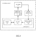
- FIG. 4 illustrates a systematic block diagram of the air mattress system 1 according to the present invention
- FIG. 5 illustrates the connection between cells configured in the air mattress 14 and the inflation and deflation device 11 of the air mattress system 1.
- the air mattress system 1 comprises an air mattress 14 and the aforesaid inflation and deflation pressure regulation system, wherein the air mattress 14 is in air communication with the inflation and deflation device 11, and the pressure detection unit 12 is employed for continuously detecting the pressure within the air mattress 14 to obtain the instantaneous pressure value to be transmitted to the control unit 13 for subsequent determination and comparison.
- the air mattress 14 comprises a first air array A and a second air array B, the first air array A comprising a first inner cell A1 and a first outer cell A2, the second air array B comprising a second inner cell B1 and a second outer cell B2, wherein the inflation and deflation device 11 may be communicated with the first outer cell A2 of the first air array A and the second outer cell B2 of the second air array B via two air delivery conduits.
- the air mattress 14 may be configured in such a way that the first outer cell A2 is communicated with the second inner cell B1 via the first check valve C1, and the second outer cell B2 is communicated with the first inner cell A1 via the second check valve C2.
- first air array A may comprise multiple sets of first inner cells A1 and first outer cells A2
- second air array B may comprise multiple sets of second inner cells B1 and second outer cells B2.
- FIG. 6 illustrates a partial flowchart of the second embodiment of the inflation and deflation pressure regulation method applicable to the above-recited air mattress system 1.
- this embodiment is different from the process exemplified in FIG. 2 in that the method shown in FIG. 6 contains an inner cell pump-up process in Step SO before the automated detection for inflation and deflation process of Step S1.
- the first air array A and the second air array B of the air mattress 14 contain respective independent inner cells and outer cells. Therefore, during the inflation operation, the first inner cell A1 and the second inner cell B1 located at the bottom have to be fully inflated to serve as a supporting base of the air mattress 14.
- Step S1 the control unit 13 may enable the inflation and deflation device 11 to inflate the first air array A and the second air array B, until the pressure in both the first air array A and the second air array B has reached the reference pressure value.
- the air discharge operation recited in Step S13 is performed for the first outer cell A2 on the first inner cell A1 or for the second outer cell B2 on the second inner cell B1, so as to proceed with the same inflation and deflation pressure regulation of the air mattress 14 using the method with only one single air array inflated.
- the inner cell pump-up process comprises a first inner cell pump-up process and a second inner cell pump-up process.
- the inflation and deflation device 11 may inflate the first outer cell A2 and the second inner cell B1.
- the first check valve C1 may prevent leakage of air filled into the second inner cell B1, such that after the second inner cell B1 and the first outer cell A2 have been inflated to an inflation pressure value, the second inner cell B1 may be maintained at the inflation pressure value; afterwards, the first outer cell A2 is then deflated to complete the second inner cell pump-up process.
- the inflation and deflation device 11 may also inflate the second outer cell B2 and the first inner cell A1.
- the second check valve C2 may prevent leakage of air filled into the first inner cell A1, such that after the first inner cell A1 and the second outer cell B2 have been inflated to the inflation pressure value, the first inner cell A1 may be maintained at the inflation pressure value; afterwards, the second outer cell B2 is then deflated to complete the first inner cell pump-up process.
- the inflation pressure value may be preset and stored for the control unit 13, and in this embodiment, the inflation pressure value may be greater than the reference pressure value but not limited thereto.
- the present invention allows inflation and deflation pressure regulation of an air mattress when the outer cell volume of each air array is fixed, so as to ensure accuracy and efficiency of air mattress inflation and deflation pressure regulation.
Landscapes
- Health & Medical Sciences (AREA)
- Nursing (AREA)
- Life Sciences & Earth Sciences (AREA)
- Animal Behavior & Ethology (AREA)
- General Health & Medical Sciences (AREA)
- Public Health (AREA)
- Veterinary Medicine (AREA)
- Invalid Beds And Related Equipment (AREA)
- Mattresses And Other Support Structures For Chairs And Beds (AREA)
Claims (11)
- Ein Aufpump- und Ablass-Druckregulierungssystem (10) für eine Luftmatratze (14) mit mindestens zwei Luftanordnungen (A, B), wobei das Aufpump- und Ablass-Druckregulierungssystem (10) Folgendes enthält:eine Aufpump- und Luftablassgerät (11) zum Aufpumpen einer Luftmatratze (14) oder zum Ablassen der Luft daraus;eine Drucküberwachungseinheit (12) zum kontinuierlichen Überwachen des momentanen Drucks der Luftmatratze (14); undeine Steuereinheit (13), die bestimmt, ob der momentane Druck, der von der Drucküberwachungseinheit (12) gemessen wird, wenn eine Luftmatratze (14), die sich unter Gewichtsbelastung befindet, einen voreingestellten Druckwert erreicht hat, bevor ein voreingestellter Zeitraum verstrichen ist; falls ja ja, die Steuereinheit (13),die eine erste Aufpump- und Luftablassstrategie verwendet, um das Aufpump- und Luftablassgerät (11) zu steuern, um die Luftmatratze (14) aufzupumpen bzw. die Luft daraus abzulassen; falls nein, die Steuereinheit (13), die eine zweite Aufpump- und Luftablassstrategie verwendet, um das Aufpump- und Luftablassgerät (11) zu steuern, um die Luftmatratze (14) aufzupumpen bzw. die Luft daraus abzulassen; dadurch gekennzeichnet, dasswenn die erste Aufpump- und Luftablassstrategie verwendet wird, die Luftmatratze (14) in Abhängigkeit vom Unterschied zwischen dem momentanen Druck und einem Zieldruck, der einer Vielzahl von verschiedenen Zeitintervallen entspricht, die jeweils der Zeitdauer entsprechen, die erforderlich ist, um den voreingestellten Druckwert zu erreichen, aufgeblasen bzw. die Luft daraus abgelassen wird; und dadurch, dasswenn die zweite Aufpump- und Luftablassstrategie verwendet wird, die Luftmatratze (14) in Abhängigkeit vom Unterschied zwischen dem momentanen Druck und einem Zieldruck, der einer Vielzahl von verschiedenen verglichenen Druckunterschieden entspricht, die sich auf einen Druckunterschied zwischen dem Bezugsdruck und dem momentanen Druck ergeben, wenn die voreingestellte Zeit verstrichen ist, aufgeblasen bzw. die Luft daraus abgelassen wird.
- Das Aufpump- und Ablass-Druckregulierungssystem (10) nach Anspruch 1, wobei vor der Bestimmung durch die Steuereinheit (13) das Aufpump- und Luftablassgerät (11) jede Luftanordnung (A, B) auf den Bezugswert aufpumpt und dann die Luft aus jeder Luftanordnung (A, B) der Luftmatratze (14) ablässt.
- Das Aufpump- und Ablass-Druckregulierungssystem (10) nach Anspruch 1, wobei das Aufpump- und Luftablassgerät (11) ferner eine Luftablasseinheit (111) enthält, die während des Betriebs des Aufpump- und Luftablassgeräts (11) eingeschaltet ist, um für Wärmeabfuhr zu sorgen.
- Das Aufpump- und Ablass-Druckregulierungssystem (10) nach Anspruch 2, wobei die Steuereinheit (13) einen Prozessor (131) und einen Analog-Digital-Wandler (132) umfasst, wobei der Prozessor (131) bestimmt, ob der momentane Druck den voreingestellten Druckdruckwert erreicht, bevor die voreingestellte Zeit verstrichen ist, während der Analog-Digital-Wandler (132) elektrisch mit dem Prozessor (131) und der Drucküberwachungseinheit (12) verbunden ist, wobei der Analog-Digital-Wandler (132) den Wert des momentanen Drucks, der von der Drucküberwachungseinheit (12) gemessen wird, verarbeitet und den verarbeiteten Wert des momentanen Drucks an den Prozessor (131) weiterleitet.
- Das Aufpump- und Ablass-Druckregulierungssystem (10) nach Anspruch 4, wobei die Steuereinheit (13) ferner einen Speicher (133) enthält, der elektrisch mit dem Prozessor (131) verbunden ist, um den Bezugsdruckwert, den Wert des momentanen Drucks, den voreingestellten Druckwert und die voreingestellte Zeit zu speichern.
- Das Aufpump- und Ablass-Druckreguherungssystem (10) nach Anspruch 1, wobei die voreingestellte Zeit ab irgendeinem Zeitpunkt innerhalb des Zeitbereichs gewählt wird.
- Ein Aufpump- und Ablassdruckregulierungssystem für eine Luftmatratze (14) mit mindestens zwei Luftanordnungen (A, B), dadurch gekennzeichnet, dass die Methode die folgenden Schritte enthält:Durchführung einer automatischen Erfassung des Aufpump- und Luftablassvorgangs,während eine Steuereinheit (13) kontinuierliche den Wert des momentanen Drucks der Luftmatratze (14) erhält, der von einer Drucküberwachungseinheit (12) gemessen wird, und es dem Aufpump- und Luftablassgerät (11) ermöglicht, die Luft in eine der Luftvorrichtungen (A, B) der Luftmatratze (14) abzulassen; Verwendung der Steuereinheit (13), um zu bestimmen, ob der Wert des momentanen Drucks der Luftmatratze (14) bei Gewichtsbelastung einen voreingestellten Wert erreicht hat, bevor die voreingestellte Zeit verstrichen ist;falls ja, verwendet die Steuereinheit (13) eine erste Aufpump- und Luftablassstrategie für die Luftmatratze (14); und falls nein, verwendet die Steuereinheit (13) eine zweite Aufpump- und Luftablassstrategie für die Luftmatratze (14);wobei, wenn die erste Aufpump- und Luftablassstrategie verwendet wird, die Luftmatratze (14) in Abhängigkeit vom Unterschied zwischen dem momentanen Druck und einem Zieldruck, der einer Vielzahl von verschiedenen Zeitintervallen entspricht, die jeweils der Zeitdauer entsprechen, die erforderlich ist, um den voreingestellten Druckwert zu erreichen, aufgeblasen bzw. die Luft daraus abgelassen wird; undwobei, wenn die zweite Aufpump- und Luftablassstrategie verwendet wird, die Luftmatratze (14) in Abhängigkeit vom Unterschied zwischen dem momentanen Druck und einem Zieldruck, der einer Vielzahl von verschiedenen verglichenen Druckunterschieden entspricht, die sich auf einen Druckunterschied zwischen dem Bezugsdruck und dem momentanen Druck ergeben, wenn die voreingestellte Zeit verstrichen ist, aufgeblasen bzw. die Luft daraus abgelassen wird.
- Die Aufpump- und Ablass-Druckregulierungsmethode nach Anspruch 7, wobei das Aufpump- und Luftablassgerät (11) in der Lage ist, die Luft durch die folgenden Schritte in eine der Luftvorrichtungen (A, B) der Luftmatratze (14) abzulassen:
Aufpumpen der beiden Luftvorrichtungen (A, B) mit dem Aufpump- und Luftablassgerät (11); Bestimmen, ob jede Luftvorrichtung (A, B) der Bezugsdruckwert erreicht hat; und falls ja, Ablassen der Luft mittels der Aufpump- und Luftablassvorrichtung (11) in eine der beiden Luftvorrichtungen (A, B) der Luftmatratze (14). - Die Aufpump- und Ablass-Druckregulierungsmethode nach Anspruch 8, die ferner die folgenden Schritte zum Aufblasen der beiden Luftvorrichtungen (A, B) mit der Luftmatratze (11) umfasst:
Das Aufpump- und Luftablassgerät (11) führt einen Innenzellen-Aufpumpvorgang an beiden Luftvorrichtungen (A, B) durch. - Ein Luftmatratzensystem (1), dadurch gekennzeichnet, dass das Luftmatratzensystem (1) Folgendes umfasst:
Eine Luftmatratze (14), bestehend aus einer ersten Luftvorrichtung (A) und einer zweiten Luftvorrichtung (B), wobei die erste Luftvorrichtung (A) einen erste Innenzelle (A1) und eine erste Außenzelle (A2) umfasst, während die zweite Luftvorrichtung (B) eine zweite Innenzelle (B1) und eine zweite Außenzelle (B2) umfasst, wobei die erste Außenzelle (A2) über ein erstes Sperrventil (C1) mit der zweiten Innenzelle (B1) in Verbindung steht, während die zweite Außenzelle (B2) über ein zweites Sperrventil (C2) mit der ersten Innenzelle (A1) in Verbindung steht; und das Aufpump- und Ablass-Druckregulierungssystem (10) nach einem der Ansprüche 1 bis 6 eine Luftverbindung mit der Luftmatratze (14) herstellt, wobei das Aufpump- und Ablass-Druckregulierungssystem (10) jede der beiden ersten Luftvorrichtungen (A) und der beiden zweiten Luftvorrichtungen (B) auf einen Bezugsdruckwert aufpumpt. - Das Luftmatratzensystem nach Anspruch 10, wobei vor dem Aufpumpen jeder der beiden ersten Luftvorrichtungen (A) und der beiden zweiten Luftvorrichtungen (B) durch das Aufpump- und Ablass-Druckregulierungssystem (10) auf den Bezugsdruckwert, das Aufpump- und Ablass-Druckregulierungssystem (10) zuerst die erste Außenzelle (A2) und die zweite Innenzelle (B1) auf einen Aufpump-Druckwert aufpumpt, woraufhin der Druck in der ersten Außenzelle (A2) abgelassen wird, um den Aufpumpvorgang der zweiten Innenzelle (B1) abzuschließen, woraufhin das Aufpump- und Ablass-Druckregulierungssystem (10) die zweite Außenzelle (B2) und die erste Innenzelle (A1) auf den Aufpump-Druckwert aufpumpt, woraufhin der Druck in der zweiten Außenzelle (B2) abgelassen wird, um den Aufpumpvorgang der ersten Innenzelle (A1) abzuschließen.
Priority Applications (1)
| Application Number | Priority Date | Filing Date | Title |
|---|---|---|---|
| EP15160249.7A EP3072419B1 (de) | 2015-03-23 | 2015-03-23 | Luftmatratzensystem und aufpump- und ablass-druckregulierungssystem und verfahren |
Applications Claiming Priority (1)
| Application Number | Priority Date | Filing Date | Title |
|---|---|---|---|
| EP15160249.7A EP3072419B1 (de) | 2015-03-23 | 2015-03-23 | Luftmatratzensystem und aufpump- und ablass-druckregulierungssystem und verfahren |
Publications (2)
| Publication Number | Publication Date |
|---|---|
| EP3072419A1 EP3072419A1 (de) | 2016-09-28 |
| EP3072419B1 true EP3072419B1 (de) | 2019-09-11 |
Family
ID=52697264
Family Applications (1)
| Application Number | Title | Priority Date | Filing Date |
|---|---|---|---|
| EP15160249.7A Active EP3072419B1 (de) | 2015-03-23 | 2015-03-23 | Luftmatratzensystem und aufpump- und ablass-druckregulierungssystem und verfahren |
Country Status (1)
| Country | Link |
|---|---|
| EP (1) | EP3072419B1 (de) |
Families Citing this family (1)
| Publication number | Priority date | Publication date | Assignee | Title |
|---|---|---|---|---|
| CN108007634B (zh) * | 2017-12-29 | 2023-09-15 | 上海邦邦机器人有限公司 | 一种用于气压检测的气囊、气囊控制系统及方法 |
Family Cites Families (4)
| Publication number | Priority date | Publication date | Assignee | Title |
|---|---|---|---|---|
| GB8417611D0 (en) * | 1984-07-10 | 1984-08-15 | Talley Medical Equipment Ltd | Control systems for air pads/mattresses |
| WO2005104904A1 (en) * | 2004-04-30 | 2005-11-10 | Tactex Controls Inc. | Body support apparatus having automatic pressure control and related methods |
| ATE478645T1 (de) * | 2004-04-30 | 2010-09-15 | Hill Rom Services Inc | Patientenunterstützung |
| GB2453371B (en) * | 2007-10-05 | 2010-06-23 | Philip James Hutchinson | Mattress pump apparatus controller, mattress pump apparatus, mattress and method of controlling a mattress |
-
2015
- 2015-03-23 EP EP15160249.7A patent/EP3072419B1/de active Active
Non-Patent Citations (1)
| Title |
|---|
| None * |
Also Published As
| Publication number | Publication date |
|---|---|
| EP3072419A1 (de) | 2016-09-28 |
Similar Documents
| Publication | Publication Date | Title |
|---|---|---|
| US10085569B2 (en) | Inflation and deflation pressure regulation system | |
| CN105982800B (zh) | 气垫床系统、充泄气调压系统及方法 | |
| JP5208732B2 (ja) | 患者支持装置内の与圧袋の制御手段 | |
| US12310905B2 (en) | Bed apparatus and patient detection method | |
| US7714238B2 (en) | Mattress seat force sensing method | |
| US9205010B2 (en) | Patient support apparatuses and methods | |
| AU2013232352B2 (en) | Compression therapy device with multiple simultaneously active chambers | |
| JP2008545513A6 (ja) | 患者支持装置内の与圧袋の制御手段 | |
| EP3076915B1 (de) | Verfahren und systeme zur automatischen kalibrierung einer pneumatischen kompressionsvorrichtung | |
| JPH02279155A (ja) | モジュール型低空気損失患者支持装置並びに自動的患者回転及び圧迫点除去方法 | |
| EP3072419B1 (de) | Luftmatratzensystem und aufpump- und ablass-druckregulierungssystem und verfahren | |
| EP2203092A1 (de) | Steuervorrichtung für eine matratzenpumpvorrichtung; matratzenpumpvorrichtung, matratze und matratzensteuerverfahren | |
| EP2201865A1 (de) | System, Vorrichtung und Verfahren zur Steuerung des internen Drucks eines aufblasbaren Kissens | |
| EP2465481B1 (de) | Methode für das Aufblasen einer aufblasbaren Matratze | |
| TWI529508B (zh) | Air cushion bed system, charge and discharge system and method |
Legal Events
| Date | Code | Title | Description |
|---|---|---|---|
| PUAI | Public reference made under article 153(3) epc to a published international application that has entered the european phase |
Free format text: ORIGINAL CODE: 0009012 |
|
| AK | Designated contracting states |
Kind code of ref document: A1 Designated state(s): AL AT BE BG CH CY CZ DE DK EE ES FI FR GB GR HR HU IE IS IT LI LT LU LV MC MK MT NL NO PL PT RO RS SE SI SK SM TR |
|
| AX | Request for extension of the european patent |
Extension state: BA ME |
|
| STAA | Information on the status of an ep patent application or granted ep patent |
Free format text: STATUS: REQUEST FOR EXAMINATION WAS MADE |
|
| 17P | Request for examination filed |
Effective date: 20170224 |
|
| RBV | Designated contracting states (corrected) |
Designated state(s): AL AT BE BG CH CY CZ DE DK EE ES FI FR GB GR HR HU IE IS IT LI LT LU LV MC MK MT NL NO PL PT RO RS SE SI SK SM TR |
|
| STAA | Information on the status of an ep patent application or granted ep patent |
Free format text: STATUS: EXAMINATION IS IN PROGRESS |
|
| 17Q | First examination report despatched |
Effective date: 20180528 |
|
| GRAP | Despatch of communication of intention to grant a patent |
Free format text: ORIGINAL CODE: EPIDOSNIGR1 |
|
| STAA | Information on the status of an ep patent application or granted ep patent |
Free format text: STATUS: GRANT OF PATENT IS INTENDED |
|
| GRAS | Grant fee paid |
Free format text: ORIGINAL CODE: EPIDOSNIGR3 |
|
| INTG | Intention to grant announced |
Effective date: 20190711 |
|
| GRAA | (expected) grant |
Free format text: ORIGINAL CODE: 0009210 |
|
| STAA | Information on the status of an ep patent application or granted ep patent |
Free format text: STATUS: THE PATENT HAS BEEN GRANTED |
|
| AK | Designated contracting states |
Kind code of ref document: B1 Designated state(s): AL AT BE BG CH CY CZ DE DK EE ES FI FR GB GR HR HU IE IS IT LI LT LU LV MC MK MT NL NO PL PT RO RS SE SI SK SM TR |
|
| REG | Reference to a national code |
Ref country code: GB Ref legal event code: FG4D |
|
| REG | Reference to a national code |
Ref country code: CH Ref legal event code: EP |
|
| REG | Reference to a national code |
Ref country code: AT Ref legal event code: REF Ref document number: 1177367 Country of ref document: AT Kind code of ref document: T Effective date: 20190915 |
|
| REG | Reference to a national code |
Ref country code: DE Ref legal event code: R096 Ref document number: 602015037602 Country of ref document: DE |
|
| REG | Reference to a national code |
Ref country code: IE Ref legal event code: FG4D |
|
| REG | Reference to a national code |
Ref country code: NL Ref legal event code: MP Effective date: 20190911 |
|
| REG | Reference to a national code |
Ref country code: LT Ref legal event code: MG4D |
|
| PG25 | Lapsed in a contracting state [announced via postgrant information from national office to epo] |
Ref country code: FI Free format text: LAPSE BECAUSE OF FAILURE TO SUBMIT A TRANSLATION OF THE DESCRIPTION OR TO PAY THE FEE WITHIN THE PRESCRIBED TIME-LIMIT Effective date: 20190911 Ref country code: LT Free format text: LAPSE BECAUSE OF FAILURE TO SUBMIT A TRANSLATION OF THE DESCRIPTION OR TO PAY THE FEE WITHIN THE PRESCRIBED TIME-LIMIT Effective date: 20190911 Ref country code: BG Free format text: LAPSE BECAUSE OF FAILURE TO SUBMIT A TRANSLATION OF THE DESCRIPTION OR TO PAY THE FEE WITHIN THE PRESCRIBED TIME-LIMIT Effective date: 20191211 Ref country code: NO Free format text: LAPSE BECAUSE OF FAILURE TO SUBMIT A TRANSLATION OF THE DESCRIPTION OR TO PAY THE FEE WITHIN THE PRESCRIBED TIME-LIMIT Effective date: 20191211 Ref country code: SE Free format text: LAPSE BECAUSE OF FAILURE TO SUBMIT A TRANSLATION OF THE DESCRIPTION OR TO PAY THE FEE WITHIN THE PRESCRIBED TIME-LIMIT Effective date: 20190911 Ref country code: HR Free format text: LAPSE BECAUSE OF FAILURE TO SUBMIT A TRANSLATION OF THE DESCRIPTION OR TO PAY THE FEE WITHIN THE PRESCRIBED TIME-LIMIT Effective date: 20190911 |
|
| PG25 | Lapsed in a contracting state [announced via postgrant information from national office to epo] |
Ref country code: RS Free format text: LAPSE BECAUSE OF FAILURE TO SUBMIT A TRANSLATION OF THE DESCRIPTION OR TO PAY THE FEE WITHIN THE PRESCRIBED TIME-LIMIT Effective date: 20190911 Ref country code: GR Free format text: LAPSE BECAUSE OF FAILURE TO SUBMIT A TRANSLATION OF THE DESCRIPTION OR TO PAY THE FEE WITHIN THE PRESCRIBED TIME-LIMIT Effective date: 20191212 Ref country code: AL Free format text: LAPSE BECAUSE OF FAILURE TO SUBMIT A TRANSLATION OF THE DESCRIPTION OR TO PAY THE FEE WITHIN THE PRESCRIBED TIME-LIMIT Effective date: 20190911 Ref country code: LV Free format text: LAPSE BECAUSE OF FAILURE TO SUBMIT A TRANSLATION OF THE DESCRIPTION OR TO PAY THE FEE WITHIN THE PRESCRIBED TIME-LIMIT Effective date: 20190911 Ref country code: ES Free format text: LAPSE BECAUSE OF FAILURE TO SUBMIT A TRANSLATION OF THE DESCRIPTION OR TO PAY THE FEE WITHIN THE PRESCRIBED TIME-LIMIT Effective date: 20190911 |
|
| REG | Reference to a national code |
Ref country code: AT Ref legal event code: MK05 Ref document number: 1177367 Country of ref document: AT Kind code of ref document: T Effective date: 20190911 |
|
| PG25 | Lapsed in a contracting state [announced via postgrant information from national office to epo] |
Ref country code: PL Free format text: LAPSE BECAUSE OF FAILURE TO SUBMIT A TRANSLATION OF THE DESCRIPTION OR TO PAY THE FEE WITHIN THE PRESCRIBED TIME-LIMIT Effective date: 20190911 Ref country code: AT Free format text: LAPSE BECAUSE OF FAILURE TO SUBMIT A TRANSLATION OF THE DESCRIPTION OR TO PAY THE FEE WITHIN THE PRESCRIBED TIME-LIMIT Effective date: 20190911 Ref country code: EE Free format text: LAPSE BECAUSE OF FAILURE TO SUBMIT A TRANSLATION OF THE DESCRIPTION OR TO PAY THE FEE WITHIN THE PRESCRIBED TIME-LIMIT Effective date: 20190911 Ref country code: IT Free format text: LAPSE BECAUSE OF FAILURE TO SUBMIT A TRANSLATION OF THE DESCRIPTION OR TO PAY THE FEE WITHIN THE PRESCRIBED TIME-LIMIT Effective date: 20190911 Ref country code: RO Free format text: LAPSE BECAUSE OF FAILURE TO SUBMIT A TRANSLATION OF THE DESCRIPTION OR TO PAY THE FEE WITHIN THE PRESCRIBED TIME-LIMIT Effective date: 20190911 Ref country code: PT Free format text: LAPSE BECAUSE OF FAILURE TO SUBMIT A TRANSLATION OF THE DESCRIPTION OR TO PAY THE FEE WITHIN THE PRESCRIBED TIME-LIMIT Effective date: 20200113 Ref country code: NL Free format text: LAPSE BECAUSE OF FAILURE TO SUBMIT A TRANSLATION OF THE DESCRIPTION OR TO PAY THE FEE WITHIN THE PRESCRIBED TIME-LIMIT Effective date: 20190911 |
|
| REG | Reference to a national code |
Ref country code: DE Ref legal event code: R082 Ref document number: 602015037602 Country of ref document: DE Representative=s name: STRAUS, ALEXANDER, DIPL.-CHEM.UNIV. DR.PHIL., DE Ref country code: DE Ref legal event code: R082 Ref document number: 602015037602 Country of ref document: DE Representative=s name: 2K PATENT- UND RECHTSANWAELTE - MUENCHEN, DE |
|
| PG25 | Lapsed in a contracting state [announced via postgrant information from national office to epo] |
Ref country code: SM Free format text: LAPSE BECAUSE OF FAILURE TO SUBMIT A TRANSLATION OF THE DESCRIPTION OR TO PAY THE FEE WITHIN THE PRESCRIBED TIME-LIMIT Effective date: 20190911 Ref country code: SK Free format text: LAPSE BECAUSE OF FAILURE TO SUBMIT A TRANSLATION OF THE DESCRIPTION OR TO PAY THE FEE WITHIN THE PRESCRIBED TIME-LIMIT Effective date: 20190911 Ref country code: CZ Free format text: LAPSE BECAUSE OF FAILURE TO SUBMIT A TRANSLATION OF THE DESCRIPTION OR TO PAY THE FEE WITHIN THE PRESCRIBED TIME-LIMIT Effective date: 20190911 Ref country code: IS Free format text: LAPSE BECAUSE OF FAILURE TO SUBMIT A TRANSLATION OF THE DESCRIPTION OR TO PAY THE FEE WITHIN THE PRESCRIBED TIME-LIMIT Effective date: 20200224 |
|
| REG | Reference to a national code |
Ref country code: DE Ref legal event code: R097 Ref document number: 602015037602 Country of ref document: DE |
|
| PLBE | No opposition filed within time limit |
Free format text: ORIGINAL CODE: 0009261 |
|
| STAA | Information on the status of an ep patent application or granted ep patent |
Free format text: STATUS: NO OPPOSITION FILED WITHIN TIME LIMIT |
|
| PG2D | Information on lapse in contracting state deleted |
Ref country code: IS |
|
| PG25 | Lapsed in a contracting state [announced via postgrant information from national office to epo] |
Ref country code: DK Free format text: LAPSE BECAUSE OF FAILURE TO SUBMIT A TRANSLATION OF THE DESCRIPTION OR TO PAY THE FEE WITHIN THE PRESCRIBED TIME-LIMIT Effective date: 20190911 Ref country code: IS Free format text: LAPSE BECAUSE OF FAILURE TO SUBMIT A TRANSLATION OF THE DESCRIPTION OR TO PAY THE FEE WITHIN THE PRESCRIBED TIME-LIMIT Effective date: 20200112 |
|
| 26N | No opposition filed |
Effective date: 20200615 |
|
| PG25 | Lapsed in a contracting state [announced via postgrant information from national office to epo] |
Ref country code: SI Free format text: LAPSE BECAUSE OF FAILURE TO SUBMIT A TRANSLATION OF THE DESCRIPTION OR TO PAY THE FEE WITHIN THE PRESCRIBED TIME-LIMIT Effective date: 20190911 |
|
| PG25 | Lapsed in a contracting state [announced via postgrant information from national office to epo] |
Ref country code: MC Free format text: LAPSE BECAUSE OF FAILURE TO SUBMIT A TRANSLATION OF THE DESCRIPTION OR TO PAY THE FEE WITHIN THE PRESCRIBED TIME-LIMIT Effective date: 20190911 |
|
| REG | Reference to a national code |
Ref country code: CH Ref legal event code: PL |
|
| REG | Reference to a national code |
Ref country code: BE Ref legal event code: MM Effective date: 20200331 |
|
| PG25 | Lapsed in a contracting state [announced via postgrant information from national office to epo] |
Ref country code: LU Free format text: LAPSE BECAUSE OF NON-PAYMENT OF DUE FEES Effective date: 20200323 |
|
| PG25 | Lapsed in a contracting state [announced via postgrant information from national office to epo] |
Ref country code: CH Free format text: LAPSE BECAUSE OF NON-PAYMENT OF DUE FEES Effective date: 20200331 Ref country code: IE Free format text: LAPSE BECAUSE OF NON-PAYMENT OF DUE FEES Effective date: 20200323 Ref country code: LI Free format text: LAPSE BECAUSE OF NON-PAYMENT OF DUE FEES Effective date: 20200331 |
|
| PG25 | Lapsed in a contracting state [announced via postgrant information from national office to epo] |
Ref country code: BE Free format text: LAPSE BECAUSE OF NON-PAYMENT OF DUE FEES Effective date: 20200331 |
|
| PG25 | Lapsed in a contracting state [announced via postgrant information from national office to epo] |
Ref country code: TR Free format text: LAPSE BECAUSE OF FAILURE TO SUBMIT A TRANSLATION OF THE DESCRIPTION OR TO PAY THE FEE WITHIN THE PRESCRIBED TIME-LIMIT Effective date: 20190911 Ref country code: MT Free format text: LAPSE BECAUSE OF FAILURE TO SUBMIT A TRANSLATION OF THE DESCRIPTION OR TO PAY THE FEE WITHIN THE PRESCRIBED TIME-LIMIT Effective date: 20190911 Ref country code: CY Free format text: LAPSE BECAUSE OF FAILURE TO SUBMIT A TRANSLATION OF THE DESCRIPTION OR TO PAY THE FEE WITHIN THE PRESCRIBED TIME-LIMIT Effective date: 20190911 |
|
| PG25 | Lapsed in a contracting state [announced via postgrant information from national office to epo] |
Ref country code: MK Free format text: LAPSE BECAUSE OF FAILURE TO SUBMIT A TRANSLATION OF THE DESCRIPTION OR TO PAY THE FEE WITHIN THE PRESCRIBED TIME-LIMIT Effective date: 20190911 |
|
| REG | Reference to a national code |
Ref country code: DE Ref legal event code: R082 Ref document number: 602015037602 Country of ref document: DE Representative=s name: STRAUS, ALEXANDER, DIPL.-CHEM.UNIV. DR.PHIL., DE |
|
| PGFP | Annual fee paid to national office [announced via postgrant information from national office to epo] |
Ref country code: DE Payment date: 20250331 Year of fee payment: 11 |
|
| PGFP | Annual fee paid to national office [announced via postgrant information from national office to epo] |
Ref country code: GB Payment date: 20260205 Year of fee payment: 12 |
|
| PGFP | Annual fee paid to national office [announced via postgrant information from national office to epo] |
Ref country code: FR Payment date: 20260205 Year of fee payment: 12 |