EP3073064B1 - Turbolader - Google Patents
Turbolader Download PDFInfo
- Publication number
- EP3073064B1 EP3073064B1 EP16165283.9A EP16165283A EP3073064B1 EP 3073064 B1 EP3073064 B1 EP 3073064B1 EP 16165283 A EP16165283 A EP 16165283A EP 3073064 B1 EP3073064 B1 EP 3073064B1
- Authority
- EP
- European Patent Office
- Prior art keywords
- vane
- stop
- guide
- turbocharger
- lever
- Prior art date
- Legal status (The legal status is an assumption and is not a legal conclusion. Google has not performed a legal analysis and makes no representation as to the accuracy of the status listed.)
- Ceased
Links
Images
Classifications
-
- F—MECHANICAL ENGINEERING; LIGHTING; HEATING; WEAPONS; BLASTING
- F04—POSITIVE - DISPLACEMENT MACHINES FOR LIQUIDS; PUMPS FOR LIQUIDS OR ELASTIC FLUIDS
- F04D—NON-POSITIVE-DISPLACEMENT PUMPS
- F04D19/00—Axial-flow pumps
- F04D19/02—Multi-stage pumps
- F04D19/04—Multi-stage pumps specially adapted to the production of a high vacuum, e.g. molecular pumps
-
- F—MECHANICAL ENGINEERING; LIGHTING; HEATING; WEAPONS; BLASTING
- F01—MACHINES OR ENGINES IN GENERAL; ENGINE PLANTS IN GENERAL; STEAM ENGINES
- F01D—NON-POSITIVE DISPLACEMENT MACHINES OR ENGINES, e.g. STEAM TURBINES
- F01D17/00—Regulating or controlling by varying flow
- F01D17/10—Final actuators
- F01D17/12—Final actuators arranged in stator parts
- F01D17/14—Final actuators arranged in stator parts varying effective cross-sectional area of nozzles or guide conduits
- F01D17/16—Final actuators arranged in stator parts varying effective cross-sectional area of nozzles or guide conduits by means of nozzle vanes
- F01D17/165—Final actuators arranged in stator parts varying effective cross-sectional area of nozzles or guide conduits by means of nozzle vanes for radial flow, i.e. the vanes turning around axes which are essentially parallel to the rotor centre line
-
- F—MECHANICAL ENGINEERING; LIGHTING; HEATING; WEAPONS; BLASTING
- F04—POSITIVE - DISPLACEMENT MACHINES FOR LIQUIDS; PUMPS FOR LIQUIDS OR ELASTIC FLUIDS
- F04D—NON-POSITIVE-DISPLACEMENT PUMPS
- F04D17/00—Radial-flow pumps, e.g. centrifugal pumps; Helico-centrifugal pumps
- F04D17/08—Centrifugal pumps
- F04D17/16—Centrifugal pumps for displacing without appreciable compression
-
- F—MECHANICAL ENGINEERING; LIGHTING; HEATING; WEAPONS; BLASTING
- F05—INDEXING SCHEMES RELATING TO ENGINES OR PUMPS IN VARIOUS SUBCLASSES OF CLASSES F01-F04
- F05D—INDEXING SCHEME FOR ASPECTS RELATING TO NON-POSITIVE-DISPLACEMENT MACHINES OR ENGINES, GAS-TURBINES OR JET-PROPULSION PLANTS
- F05D2220/00—Application
- F05D2220/40—Application in turbochargers
-
- F—MECHANICAL ENGINEERING; LIGHTING; HEATING; WEAPONS; BLASTING
- F05—INDEXING SCHEMES RELATING TO ENGINES OR PUMPS IN VARIOUS SUBCLASSES OF CLASSES F01-F04
- F05D—INDEXING SCHEME FOR ASPECTS RELATING TO NON-POSITIVE-DISPLACEMENT MACHINES OR ENGINES, GAS-TURBINES OR JET-PROPULSION PLANTS
- F05D2230/00—Manufacture
- F05D2230/50—Building or constructing in particular ways
- F05D2230/54—Building or constructing in particular ways by sheet metal manufacturing
-
- F—MECHANICAL ENGINEERING; LIGHTING; HEATING; WEAPONS; BLASTING
- F05—INDEXING SCHEMES RELATING TO ENGINES OR PUMPS IN VARIOUS SUBCLASSES OF CLASSES F01-F04
- F05D—INDEXING SCHEME FOR ASPECTS RELATING TO NON-POSITIVE-DISPLACEMENT MACHINES OR ENGINES, GAS-TURBINES OR JET-PROPULSION PLANTS
- F05D2230/00—Manufacture
- F05D2230/60—Assembly methods
- F05D2230/61—Assembly methods using limited numbers of standard modules which can be adapted by machining
-
- F—MECHANICAL ENGINEERING; LIGHTING; HEATING; WEAPONS; BLASTING
- F05—INDEXING SCHEMES RELATING TO ENGINES OR PUMPS IN VARIOUS SUBCLASSES OF CLASSES F01-F04
- F05D—INDEXING SCHEME FOR ASPECTS RELATING TO NON-POSITIVE-DISPLACEMENT MACHINES OR ENGINES, GAS-TURBINES OR JET-PROPULSION PLANTS
- F05D2230/00—Manufacture
- F05D2230/60—Assembly methods
- F05D2230/64—Assembly methods using positioning or alignment devices for aligning or centring, e.g. pins
- F05D2230/644—Assembly methods using positioning or alignment devices for aligning or centring, e.g. pins for adjusting the position or the alignment, e.g. wedges or eccenters
-
- F—MECHANICAL ENGINEERING; LIGHTING; HEATING; WEAPONS; BLASTING
- F05—INDEXING SCHEMES RELATING TO ENGINES OR PUMPS IN VARIOUS SUBCLASSES OF CLASSES F01-F04
- F05D—INDEXING SCHEME FOR ASPECTS RELATING TO NON-POSITIVE-DISPLACEMENT MACHINES OR ENGINES, GAS-TURBINES OR JET-PROPULSION PLANTS
- F05D2260/00—Function
- F05D2260/30—Retaining components in desired mutual position
Definitions
- the invention relates to a turbocharger according to the preamble of claim 1.
- Such a turbocharger is from the EP 1 564 380 A1 known.
- this document proposes a stop which is integrally connected to the adjusting ring.
- the projection of the stop of the known turbocharger limits the end positions by contact with mounting rings of the adjusting lever on the blades, which also makes precise adjustment of the end positions difficult, since the mounting rings of these blade adjustment levers are subject to manufacturing tolerances and on the other hand, due to the positioning (division) inaccuracies arise.
- turbocharger specified in the preamble of claim 1, which allows a simplification of the assembly of the guide grid or diffuser, at least a simple and accurate adjustment of the minimum flow through the diffuser should be possible alone.
- the stop with which at least one setting of the minimum flow through the nozzle cross-sections formed by the vanes is possible, is formed as a separate component which is fixable in the guide grid, it is possible after mounting the guide grid this stop in a simple way and way to rework the exact setting of the required stop position, since it is not integrally connected to the guide grid. If the need for a readjustment of one of the two end positions of the guide grid, it can be either simply selected and mounted a suitable fitment for the desired end position or adapted the intended stop member by reworking the projection and then mounted in the guide grille. Thus, it is possible to make a precise end position targeted, which is problematic in the generic turbocharger due to the integral formation of the stop.
- the entire diffuser can be completely pre-assembled as a cartridge and the minimum flow can be adjusted before it is then inserted into the turbine housing.
- the adjustment of the minimum flow is thus independent of turbine housing and other components of the turbocharger, such as e.g. the bearing housing. Also, the nozzle position between the bearing and turbine housing no longer has any influence on the minimum flow setting. Also, the wear of the adjusting lever and its engagement with the adjusting ring does not affect the minimum flow rate.
- a guide grid is defined as each independently tradable objects.
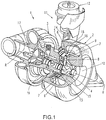
- FIG. 1 an inventive turbocharger 1 is shown, which has a turbine housing 2 and a compressor housing 3 connected thereto via a bearing housing 19.
- the housings 2, 3 and 19 are arranged along a rotation axis R.
- the turbine housing 2 is shown partially in section to illustrate the arrangement of a vane ring 6 as part of a radially outer baffle 18 having a plurality of circumferentially spaced vanes 7 with pivot shafts 8.
- nozzle cross-sections are formed, which are larger or smaller depending on the position of the guide vanes 7 and the turbine rotor 4 mounted in the middle on the axis of rotation R more or less with the supplied via a feed channel 9 and discharged via a central port 10 exhaust gas of an engine, to drive over the turbine rotor 4 a seated on the same shaft compressor rotor 17.
- an actuating device 11 is provided.
- This can be designed to be arbitrary, but a preferred embodiment, a control housing 12, which controls the control movement of a ram member 14 attached to her to implement the movement thereof to a located behind the blade bearing ring 6 adjusting 5 in a slight rotational movement of the same.
- a clearance 13 for the vanes 7 is formed between the vane ring 6 and an annular part 15 of the turbine housing 2.
- the blade bearing ring 6 has integrally formed spacers 16.
- three spacers 16 are arranged at an angular distance of 120 ° in each case on the circumference of the blade bearing ring 6. In principle, it is However, it is possible to provide more or less such spacers 16.
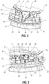
- Fig. 2 is a partial perspective view of the guide grid 18 shown on an enlarged scale.
- a blade lever 20 is shown having at one end a mounting ring 21 with a recess 22 in which one end of the blade shaft 8 is fixed.
- a lever head 23 of the blade lever 20 is disposed in an engagement recess 24 of the adjusting ring 5 and thus is engaged with the adjusting ring 5 in engagement.
- FIG. 2 the arrangement of a stop 25 in the form of a separate component.
- the stop 25 has a stop body 26, which has been fixed in the illustrated embodiment on the blade bearing ring 6.
- the stopper body 6 has a radially outwardly projecting projection 27, which engages in a groove 31 of the adjusting ring 5.
- the groove 31 of the adjusting ring 5 is bounded by two stop cams 29 and 30.
- the stop cams 29 and 30 have inwardly into the groove 31 facing abutment abutment surfaces which can engage with the corresponding adjacent surface of the projection 27.
- a stop position on the stop cam 29 for adjusting the minimum flow through the nozzle cross sections of the guide grid 18 is shown.
- a stop web 28 is arranged at the upper end of a side facing the stop cam 29 side surface 34 which extends at right angles to the side surface 34.
- This stop bar 28 can be reworked for exact position adjustment in case of need, should In the course of the assembly of the guide grid 18 it turns out that the exact position can not yet be set.
- the stop 25 can then be separated from the blade bearing ring 6 and be reworked in a precision device by removing a suitable portion of the stop web 28.
- Fig. 3 an embodiment of the guide grid 18 according to the invention is shown.
- all parts that are those of Fig. 2 provided with the same reference numerals, so that reference can be made in terms of training and function to the above description.
- the stop 25 of the second embodiment is provided with an adjusting plate 32.
- the adjusting plate 32 has a fixing plate 35 which can be fixed to the stopper body 26, such as by a Fixierclip 36.
- Fixierclip 36 any other types of mounting options for the adjusting plate 32 on the stopper body 26 are conceivable.
- the adjusting plate 32 is provided in this embodiment with a stop plate 33 which extends parallel to the side surface 34 of the projection 27 and to this one Fig. 3 apparent distance, so as to be able to define the exact stop position.
- the stop position can be effected by the replacement of the adjusting plate 32, so that in this embodiment, an exact adjustment, in particular the minimum flow, in a simple and cost-effective manner is possible.
Landscapes
- Engineering & Computer Science (AREA)
- Mechanical Engineering (AREA)
- General Engineering & Computer Science (AREA)
- Supercharger (AREA)
- Control Of Turbines (AREA)
Applications Claiming Priority (2)
| Application Number | Priority Date | Filing Date | Title |
|---|---|---|---|
| DE102006023923 | 2006-05-19 | ||
| EP07725312.8A EP2018480B1 (de) | 2006-05-19 | 2007-05-16 | Turbolader |
Related Parent Applications (2)
| Application Number | Title | Priority Date | Filing Date |
|---|---|---|---|
| EP07725312.8A Division-Into EP2018480B1 (de) | 2006-05-19 | 2007-05-16 | Turbolader |
| EP07725312.8A Division EP2018480B1 (de) | 2006-05-19 | 2007-05-16 | Turbolader |
Publications (2)
| Publication Number | Publication Date |
|---|---|
| EP3073064A1 EP3073064A1 (de) | 2016-09-28 |
| EP3073064B1 true EP3073064B1 (de) | 2017-09-20 |
Family
ID=38353448
Family Applications (2)
| Application Number | Title | Priority Date | Filing Date |
|---|---|---|---|
| EP16165283.9A Ceased EP3073064B1 (de) | 2006-05-19 | 2007-05-16 | Turbolader |
| EP07725312.8A Ceased EP2018480B1 (de) | 2006-05-19 | 2007-05-16 | Turbolader |
Family Applications After (1)
| Application Number | Title | Priority Date | Filing Date |
|---|---|---|---|
| EP07725312.8A Ceased EP2018480B1 (de) | 2006-05-19 | 2007-05-16 | Turbolader |
Country Status (7)
| Country | Link |
|---|---|
| US (1) | US8328520B2 (pt) |
| EP (2) | EP3073064B1 (pt) |
| JP (1) | JP2009537727A (pt) |
| KR (1) | KR101400878B1 (pt) |
| CN (1) | CN101438062A (pt) |
| BR (1) | BRPI0709404B1 (pt) |
| WO (1) | WO2007134787A1 (pt) |
Families Citing this family (25)
| Publication number | Priority date | Publication date | Assignee | Title |
|---|---|---|---|---|
| US8545173B2 (en) | 2008-02-12 | 2013-10-01 | Honeywell International, Inc. | Process for calibrating a variable-nozzle assembly of a turbocharger and a variable-nozzle assembly facilitating such process |
| US8122716B2 (en) * | 2008-06-04 | 2012-02-28 | Honeywell International Inc. | VNT flow calibration adjustment |
| DE102008035749B4 (de) | 2008-07-31 | 2018-05-30 | Bosch Mahle Turbo Systems Gmbh & Co. Kg | Abgasturbolader |
| CA2737516A1 (en) * | 2008-09-18 | 2010-03-25 | Siemens Aktiengesellschaft | Method, system, device for variable guide vanes |
| DE102008053170A1 (de) | 2008-10-24 | 2010-04-29 | Bosch Mahle Turbo Systems Gmbh & Co. Kg | Ladeeinrichtung mit variabler Turbinen-/Verdichtergeometrie, insbesondere für einen Abgasturbolader eines Kraftfahrzeugs |
| KR101031633B1 (ko) * | 2009-04-17 | 2011-04-27 | (주)계양정밀 | 가변 지오메트리 터보차져의 노즐어셈블리 및 그 제작방법 |
| DE112010004597B4 (de) | 2009-11-27 | 2022-05-25 | Borgwarner Inc. | Turbolader mit variabler Turbinengeometrie |
| KR101671832B1 (ko) * | 2009-11-27 | 2016-11-03 | 보르그워너 인코퍼레이티드 | 터보차저의 가이드 장치 |
| DE102009057664A1 (de) * | 2009-12-09 | 2011-06-16 | Ihi Charging Systems International Gmbh | Verstelleinrichtung für eine Aufladeeinrichtung, insbesondere für einen Abgasturbolader |
| DE112011100758B4 (de) | 2010-03-03 | 2022-10-06 | Borgwarner Inc. | Kostenreduzierter Turbolader mit variabler Geometrie mit gestanzter Verstellringanordnung |
| JP5787988B2 (ja) * | 2010-05-19 | 2015-09-30 | ボーグワーナー インコーポレーテッド | ターボチャージャ |
| DE112011103045T5 (de) * | 2010-09-27 | 2013-07-04 | Borgwarner Inc. | Verfahren zur Herstellung eines Turboladers |
| DE102010043145B4 (de) | 2010-10-29 | 2022-02-10 | BMTS Technology GmbH & Co. KG | Variable Turbinen-/Verdichtergeometrie |
| CN103189613B (zh) * | 2010-12-08 | 2015-11-25 | 博格华纳公司 | 排气涡轮增压器 |
| CN103635671B (zh) * | 2011-08-08 | 2016-01-20 | 博格华纳公司 | 涡轮增压器 |
| WO2013116136A1 (en) * | 2012-02-02 | 2013-08-08 | Borgwarner Inc. | Mixed-flow turbocharger with variable turbine geometry |
| IN2014DN06183A (pt) * | 2012-04-27 | 2015-10-23 | Borgwarner Inc | |
| WO2014081602A1 (en) * | 2012-11-23 | 2014-05-30 | Borgwarner Inc. | Exhaust-gas turbocharger |
| US9988975B2 (en) | 2013-03-11 | 2018-06-05 | Borgwarner Inc. | Exhaust-gas turbocharger |
| JP5984789B2 (ja) * | 2013-12-16 | 2016-09-06 | 株式会社アキタファインブランキング | Vgsタイプターボチャージャにおける排気ガイドアッセンブリ |
| DE102016203025A1 (de) * | 2016-02-26 | 2017-08-31 | Bosch Mahle Turbo Systems Gmbh & Co. Kg | Variable Turbinengeometrie |
| WO2018029985A1 (ja) * | 2016-08-08 | 2018-02-15 | 株式会社Ihi | 可変容量型過給機 |
| WO2018037807A1 (ja) | 2016-08-24 | 2018-03-01 | 株式会社Ihi | 可変容量型過給機 |
| CN112805462B (zh) * | 2018-10-09 | 2022-05-27 | 株式会社Ihi | 可变容量机构以及增压器 |
| DE102020103215A1 (de) * | 2020-02-07 | 2021-08-12 | Ihi Charging Systems International Gmbh | Verstellbarer Leitapparat für einen Abgasführungsabschnitt eines Abgasturboladers, Abgasführungsabschnitt für einen Abgasturbolader und Abgasturbolader |
Family Cites Families (12)
| Publication number | Priority date | Publication date | Assignee | Title |
|---|---|---|---|---|
| DE2455361A1 (de) * | 1973-12-11 | 1975-06-12 | Plessey Handel Investment Ag | Turbine bzw. kompressor insbesondere fuer turbolader |
| US4695220A (en) * | 1985-09-13 | 1987-09-22 | General Electric Company | Actuator for variable vanes |
| US4741666A (en) | 1985-12-23 | 1988-05-03 | Ishikawajima-Harima Jukogyo Kabushiki Kaisha | Variable displacement turbocharger |
| FR2648182B1 (fr) * | 1989-06-07 | 1991-08-30 | Snecma | Systeme de verrouillage provisoire de positionnement d'aubes a calage variable pendant le montage et turbomachine le comportant |
| DE3941715A1 (de) * | 1989-12-18 | 1991-06-20 | Porsche Ag | Abgasturbolader fuer eine brennkraftmaschine |
| JPH1037754A (ja) * | 1996-07-24 | 1998-02-10 | Toyota Motor Corp | 可変ノズルターボチャージャ |
| DE10035762A1 (de) * | 2000-07-22 | 2002-01-31 | Daimler Chrysler Ag | Abgasturbolader für eine Brennkraftmaschine und Verfahren zum Betrieb eines Abgasturboladers |
| JP3764653B2 (ja) * | 2001-02-27 | 2006-04-12 | 三菱重工業株式会社 | 可変ノズル機構のノズル開度規制装置およびその製作方法 |
| JP3809361B2 (ja) * | 2001-10-22 | 2006-08-16 | トヨタ自動車株式会社 | アクチュエータの制御装置 |
| EP1564380A1 (de) | 2004-02-17 | 2005-08-17 | BorgWarner Inc. | Turbineneinheit sowie Leitgitter und Verstellring hierfür |
| GB0407978D0 (en) * | 2004-04-08 | 2004-05-12 | Holset Engineering Co | Variable geometry turbine |
| DE102004043927A1 (de) * | 2004-09-11 | 2006-04-13 | Ihi Charging Systems International Gmbh | Stelleinrichtung für Leitschaufeln eines Abgasturboladers |
-
2007
- 2007-05-16 BR BRPI0709404-3A patent/BRPI0709404B1/pt not_active IP Right Cessation
- 2007-05-16 JP JP2009510355A patent/JP2009537727A/ja active Pending
- 2007-05-16 CN CNA2007800165695A patent/CN101438062A/zh active Pending
- 2007-05-16 WO PCT/EP2007/004397 patent/WO2007134787A1/de not_active Ceased
- 2007-05-16 US US12/300,260 patent/US8328520B2/en not_active Expired - Fee Related
- 2007-05-16 EP EP16165283.9A patent/EP3073064B1/de not_active Ceased
- 2007-05-16 KR KR1020087027831A patent/KR101400878B1/ko not_active Expired - Fee Related
- 2007-05-16 EP EP07725312.8A patent/EP2018480B1/de not_active Ceased
Non-Patent Citations (1)
| Title |
|---|
| None * |
Also Published As
| Publication number | Publication date |
|---|---|
| JP2009537727A (ja) | 2009-10-29 |
| KR101400878B1 (ko) | 2014-05-29 |
| US8328520B2 (en) | 2012-12-11 |
| EP2018480B1 (de) | 2016-06-15 |
| CN101438062A (zh) | 2009-05-20 |
| EP2018480A1 (de) | 2009-01-28 |
| BRPI0709404B1 (pt) | 2019-08-06 |
| BRPI0709404A2 (pt) | 2011-07-12 |
| WO2007134787A1 (de) | 2007-11-29 |
| US20100014961A1 (en) | 2010-01-21 |
| EP3073064A1 (de) | 2016-09-28 |
| KR20090010199A (ko) | 2009-01-29 |
Similar Documents
| Publication | Publication Date | Title |
|---|---|---|
| EP3073064B1 (de) | Turbolader | |
| EP1984601B1 (de) | Turbolader mit verstellbaren leitschaufeln, schaufelhebel und verstellring dafür | |
| EP2078136B1 (de) | Reibgeschweisste turboladerwelle und herstellungsverfahren dafür | |
| EP2002127B1 (de) | Vordrall-leitvorrichtung | |
| DE112010004597B4 (de) | Turbolader mit variabler Turbinengeometrie | |
| EP2209969B1 (de) | Ladeeinrichtung | |
| EP2131042B1 (de) | Regelbare Kühlmittelpumpe für den Kühlkreislauf einer Verbrennungskraftmaschine | |
| EP2989298B1 (de) | Abgasturbolader | |
| DE102012206338B4 (de) | Nockenwellenversteller mit Stator-Deckel-Einheit zur automatischen Einstellung eines Verriegelungsspiels | |
| DE112012002746T5 (de) | Abgasturbolader | |
| DE112011103045T5 (de) | Verfahren zur Herstellung eines Turboladers | |
| EP3333374B1 (de) | Leitschaufelverstellung mit seitlich montiertem verstellhebel und zugehöriges herstellungsverfahren | |
| EP1520959B1 (de) | Turbokompressor mit verstellbaren Leitschaufeln | |
| DE112019006143B4 (de) | Ventileinrichtung für einen Abgasturbolader und Abgasturbolader | |
| WO2006060925A1 (de) | Leitapparat für abgasturbine | |
| EP1734231B1 (de) | Turbolader mit variabler turbinengeometrie | |
| EP1564380A1 (de) | Turbineneinheit sowie Leitgitter und Verstellring hierfür | |
| DE112011101698T5 (de) | Turbolader | |
| DE112010004596T5 (de) | Turbolade | |
| EP1998026A2 (de) | Ladeeinrichtung | |
| EP2510207B1 (de) | Verstelleinrichtung für eine Aufladeeinrichtung, insbesondere für einen Abgasturbolader | |
| EP2317081B1 (de) | Variable Turbinen- und/oder Verdichtergeometrie | |
| DE102004031986B4 (de) | Abgasturbolader für eine Brennkraftmaschine | |
| DE10311227B4 (de) | Leitapparat | |
| DE102004030798A1 (de) | Abgasturbolader für eine Brennkraftmaschine mit variabler Turbinengeometrie |
Legal Events
| Date | Code | Title | Description |
|---|---|---|---|
| PUAI | Public reference made under article 153(3) epc to a published international application that has entered the european phase |
Free format text: ORIGINAL CODE: 0009012 |
|
| AC | Divisional application: reference to earlier application |
Ref document number: 2018480 Country of ref document: EP Kind code of ref document: P |
|
| AK | Designated contracting states |
Kind code of ref document: A1 Designated state(s): DE FR GB IT NL |
|
| 17P | Request for examination filed |
Effective date: 20170127 |
|
| RBV | Designated contracting states (corrected) |
Designated state(s): DE FR GB IT NL |
|
| GRAP | Despatch of communication of intention to grant a patent |
Free format text: ORIGINAL CODE: EPIDOSNIGR1 |
|
| INTG | Intention to grant announced |
Effective date: 20170526 |
|
| GRAS | Grant fee paid |
Free format text: ORIGINAL CODE: EPIDOSNIGR3 |
|
| GRAA | (expected) grant |
Free format text: ORIGINAL CODE: 0009210 |
|
| AC | Divisional application: reference to earlier application |
Ref document number: 2018480 Country of ref document: EP Kind code of ref document: P |
|
| AK | Designated contracting states |
Kind code of ref document: B1 Designated state(s): DE FR GB IT NL |
|
| REG | Reference to a national code |
Ref country code: GB Ref legal event code: FG4D Free format text: NOT ENGLISH |
|
| REG | Reference to a national code |
Ref country code: DE Ref legal event code: R096 Ref document number: 502007015887 Country of ref document: DE |
|
| REG | Reference to a national code |
Ref country code: NL Ref legal event code: FP |
|
| REG | Reference to a national code |
Ref country code: FR Ref legal event code: PLFP Year of fee payment: 12 |
|
| PG25 | Lapsed in a contracting state [announced via postgrant information from national office to epo] |
Ref country code: IT Free format text: LAPSE BECAUSE OF FAILURE TO SUBMIT A TRANSLATION OF THE DESCRIPTION OR TO PAY THE FEE WITHIN THE PRESCRIBED TIME-LIMIT Effective date: 20170920 |
|
| REG | Reference to a national code |
Ref country code: DE Ref legal event code: R097 Ref document number: 502007015887 Country of ref document: DE |
|
| PLBE | No opposition filed within time limit |
Free format text: ORIGINAL CODE: 0009261 |
|
| STAA | Information on the status of an ep patent application or granted ep patent |
Free format text: STATUS: NO OPPOSITION FILED WITHIN TIME LIMIT |
|
| 26N | No opposition filed |
Effective date: 20180621 |
|
| PGFP | Annual fee paid to national office [announced via postgrant information from national office to epo] |
Ref country code: NL Payment date: 20190429 Year of fee payment: 13 |
|
| PGFP | Annual fee paid to national office [announced via postgrant information from national office to epo] |
Ref country code: DE Payment date: 20190412 Year of fee payment: 13 |
|
| PGFP | Annual fee paid to national office [announced via postgrant information from national office to epo] |
Ref country code: FR Payment date: 20190417 Year of fee payment: 13 |
|
| PGFP | Annual fee paid to national office [announced via postgrant information from national office to epo] |
Ref country code: GB Payment date: 20190430 Year of fee payment: 13 |
|
| REG | Reference to a national code |
Ref country code: DE Ref legal event code: R119 Ref document number: 502007015887 Country of ref document: DE |
|
| REG | Reference to a national code |
Ref country code: NL Ref legal event code: MM Effective date: 20200601 |
|
| PG25 | Lapsed in a contracting state [announced via postgrant information from national office to epo] |
Ref country code: NL Free format text: LAPSE BECAUSE OF NON-PAYMENT OF DUE FEES Effective date: 20200601 |
|
| GBPC | Gb: european patent ceased through non-payment of renewal fee |
Effective date: 20200516 |
|
| PG25 | Lapsed in a contracting state [announced via postgrant information from national office to epo] |
Ref country code: GB Free format text: LAPSE BECAUSE OF NON-PAYMENT OF DUE FEES Effective date: 20200516 Ref country code: FR Free format text: LAPSE BECAUSE OF NON-PAYMENT OF DUE FEES Effective date: 20200531 |
|
| PG25 | Lapsed in a contracting state [announced via postgrant information from national office to epo] |
Ref country code: DE Free format text: LAPSE BECAUSE OF NON-PAYMENT OF DUE FEES Effective date: 20201201 |