EP3073192B1 - Kleidungsausrüstung zur aktiven sicherheit oder ein mittel zur reihenbestrahlung - Google Patents
Kleidungsausrüstung zur aktiven sicherheit oder ein mittel zur reihenbestrahlung Download PDFInfo
- Publication number
- EP3073192B1 EP3073192B1 EP16162316.0A EP16162316A EP3073192B1 EP 3073192 B1 EP3073192 B1 EP 3073192B1 EP 16162316 A EP16162316 A EP 16162316A EP 3073192 B1 EP3073192 B1 EP 3073192B1
- Authority
- EP
- European Patent Office
- Prior art keywords
- light source
- light
- light guide
- housing
- led
- Prior art date
- Legal status (The legal status is an assumption and is not a legal conclusion. Google has not performed a legal analysis and makes no representation as to the accuracy of the status listed.)
- Active
Links
Images


Classifications
-
- F—MECHANICAL ENGINEERING; LIGHTING; HEATING; WEAPONS; BLASTING
- F21—LIGHTING
- F21V—FUNCTIONAL FEATURES OR DETAILS OF LIGHTING DEVICES OR SYSTEMS THEREOF; STRUCTURAL COMBINATIONS OF LIGHTING DEVICES WITH OTHER ARTICLES, NOT OTHERWISE PROVIDED FOR
- F21V33/00—Structural combinations of lighting devices with other articles, not otherwise provided for
- F21V33/0004—Personal or domestic articles
- F21V33/0008—Clothing or clothing accessories, e.g. scarfs, gloves or belts
-
- A—HUMAN NECESSITIES
- A41—WEARING APPAREL
- A41D—OUTERWEAR; PROTECTIVE GARMENTS; ACCESSORIES
- A41D13/00—Professional, industrial or sporting protective garments, e.g. surgeons' gowns or garments protecting against blows or punches
- A41D13/01—Professional, industrial or sporting protective garments, e.g. surgeons' gowns or garments protecting against blows or punches with reflective or luminous safety means
Definitions
- the invention relates to light source for active safety clothing equipment or a means of line irradiation with a side-emitting light guide enclosed in a textile sheath provided with at least one fastening means for attachment to a carrier element or clothing on at least part of the length of the light guide while the light source is connectable with a source of electrical energy.
- passive retro-reflective elements and/or actively light-emitting elements positioned on the outer side of the clothing that are used most often.
- the actively light-emitting elements are typically based on battery-powered groups of lighting units, particularly LEDs, which are mounted onto the surface of a carrier means.
- the advantage of the passive retro-reflective elements is their zero energy consumption and high mechanical resistance.
- the advantage of the actively light-emitting elements is their functionality even without external irradiation which is possible due to internal power supply.
- the greatest drawback of the use of the passive retro-reflective elements is the fact that their functionality is limited only to situations when the element is irradiated by an external source of light (e.g. car lights, etc.). This is unfavourable especially in situations, such as when a person moving along the road or in its vicinity is not irradiated by the headlights of a car until at a certain moment, and is therefore seen by the driver later than could have been seen, which applies especially to bends and other less clear sections of the road.
- an external source of light e.g. car lights, etc.
- the greatest disadvantage of actively radiating elements is the necessity of ensuring their power supply, usually by using batteries, whereby for highlighting a larger area it is necessary to use a plurality of light-emitting elements (units), e.g. LEDs, which then consume a greater amount of energy.
- this arrangement occupies a relatively vast area and is therefore hardly suitable for clothing, also because it is bulky and inflexible or, in other words, has limited flexibility, and, last but not least, each of the illuminating elements is dependent on power supply delivered directly into it, which is from the technical point of view considerably demanding, especially when trying to achieve a high quality and durability.
- a line source of light that is used (fluorescent tubes), or a row of point sources of light arranged behind one another (bulbs, LEDs). This relates especially to the illumination within corridors or hallways, creating light direction indicators or the light marking of obstacles in a path, the light marking of outlines of objects, the highlighting of edges, such as stairs, emergency exits, etc.
- LEDs arranged in a band seem to be more advantageous than bulbs, discharge lamps and fluorescent tubes, LEDs exhibit a high light intensity, which often even dazzles and must be attenuated by various filters, which makes their use more expensive.
- Another shortcoming is the fact that the construction of a band of a group of LEDs leads to formation of a longitudinal element with a relatively limited flexibility.
- a common disadvantage of bulbs, LEDs, discharge lamps and fluorescent tubes is the necessity to secure corresponding power supply for each elementary light source.
- Another drawback is their limited applicability in regions with no power supply, especially during power outages, since their relatively high energy consumption puts high demands on securing alternative sources of electrical energy.
- a common problem of point light sources is local over-illumination which causes illumination of only a relatively limited space around the light source.
- the aim of the invention is to remove or at least minimize the drawbacks of the background art.
- the goal of the invention is achieved by light source for active safety clothing equipment, whose principle consists in that the light source comprises an LED or laser diode with the maximum radiating angle of 50° (FWHM) and the radiation output in the range from 10 to 500 Im, whereby the LED or laser diode is connected to an aluminium board and a printed circuit of the electronics of the light source and the light source is equipped with orifice for enter the light guide with its inlet end to the inner space of a housing and is further equipped with at least one centering means for holding the inlet end of the light guide in a stable position in relation to the LED or laser diode and the whole set is mounted in the housing in a waterproof manner.
- the light source comprises an LED or laser diode with the maximum radiating angle of 50° (FWHM) and the radiation output in the range from 10 to 500 Im
- the LED or laser diode is connected to an aluminium board and a printed circuit of the electronics of the light source and the light source is equipped with orifice for enter the light guide with its inlet end to
- the advantage of this arrangement is the fact that it enables to create an actively light-emitting clothing equipment or a means of line irradiation with minimum energy consumption, which is easily usable on different garments, is easily wearable and is also widely configurable in terms of the arrangement of irradiated parts, etc.
- Other advantages include the absence of local over-illumination or glare, long life, low energy consumption, resistance to damage of the light guide, color variability, easy replacement, etc.
- Examples include carpet edges, bath sets, outdoor rugs and doormats, escape routes and exits, marking of the shape of stairways, lifts or hospital beds, road barriers, premises for the police, firefighters, rescue services or construction sites or landing and parking areas for air and land means of transportation, wherein due to high uniformity of illumination there is no local over-illumination and the light source is not dazzling.
- Another advantage is the possibility of highlighting parts of objects which have their own electrical system, such as ships, cars, motorcycles.
- Other uses include, for example, highlighting canvas of lorries or trucks, opened doors, local illumination of the interior, etc.
- Other possible applications relate to illumination to ensure greater safety in conditions of reduced visibility, e.g. illumination of bicycles, baby carriages, wheelchairs and carts, canes and crutches, warning signs including warning triangles, etc.
- Another field of application is illumination for advertising purposes and in industrial processes.
- Fig. 1 shows the first embodiment of a side-emitting light guide for active safety clothing equipment
- Fig. 2 shows the second embodiment of a side-emitting light guide for the active safety clothing equipment
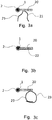
- Fig. 3a is a cross-section of the side-emitting light guide for active safety clothing equipment according to Fig. 1
- Fig. 3a is a cross-section of the side-emitting light guide for active safety clothing equipment according to Fig. 1 with attachment means in the form of laces
- Fig. 3b represents a cross-section of the side-emitting light guide for active safety clothing equipment according to Fig. 1 with an attachment means in the form of an adhesive layer
- Fig. 1 shows the first embodiment of a side-emitting light guide for active safety clothing equipment
- Fig. 2 shows the second embodiment of a side-emitting light guide for the active safety clothing equipment
- Fig. 3a is a cross-section of the side-emitting light guide for active safety clothing equipment according to Fig. 1 with attachment
- FIG. 3c is a cross-sectional view of the side-emitting light guide for active safety clothing equipment according to Fig. 1 with attachment means in the form of Velcros
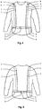
- Fig. 4 is a front view of the clothing for the upper part of the body (a jacket) with the attached active safety clothing equipment in the form of illuminating braces or suspenders
- Fig. 5 is a rear view of the clothing for the upper part of the body (a jacket) with the attached active safety clothing equipment in the form of illuminating braces or suspenders
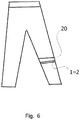
- Fig. 6 is a front view of the clothing for the lower part of the body (trousers) the attached active safety clothing equipment in the form of a stripe on trousers
- Fig. 4 is a front view of the clothing for the upper part of the body (a jacket) with the attached active safety clothing equipment in the form of illuminating braces or suspenders
- Fig. 5 is a rear view of the clothing for the upper part of the body (a jacket) with the attached active safety clothing equipment in the form
- FIG. 7 shows an exemplary embodiment of a means of line irradiation with a side-emitting light guide with one textile stripe
- Fig. 8 shows an embodiment of a means of line irradiation with a side-emitting light guide having a pair of textile stripes
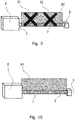
- Fig. 9 shows a means of line irradiation with a textile sheath, a light guide, a light source and a reflective means
- Fig. 10 represents a means of line irradiation with a textile sheath, a light guide, a light source and a reflective means
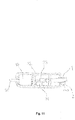
- Fig. 11 illustrates an exemplary embodiment of a light source.
- Active safety clothing equipment or a means of line irradiation contains at least one active side-emitting light guide 1 , e.g. according to WO 2014/071898 , which is enclosed in a textile sheath 2 , which protects the light guide 1 and at the same time serves to attach the light guide 1 to the clothing, on which it constitutes active safety clothing equipment or a means of line irradiation together with the hereinafter described light source and a control unit.
- the light emitted by the light source 3 is side emitted by the light guide 1 to the environment through the textile sheath 2 and due to diffuse scattering appears to be more intense and more uniform, as has been experimentally confirmed.
- the side-emitting light guide 1 is at least with one of its ends detachably or fixedly connected to the light source 3 , which is used for introducing light into the light guide 1 , whereby this light is side emitted by the light guide 1 to the environment through the textile sheath 2 and due to diffuse scattering appears to be more intense and more uniform than the light radiated by the light guide without a textile sheath, as has been experimentally confirmed.
- the textile sheath 2 is at least on part of the length of the light guide provided with at least one textile stripe 20 (see Figs. 1 to 3 ), whereby the textile stripe 20 acts as an attachment or a mounting means for the textile sheath 2 with the light guide 1 to attach it to a carrier or to mount it on the carrier.
- the width of the textile stripe is usually in the range of 2 cm to 5 cm. Nevertheless, in general, it is possible to create a textile sheath 2 with a light guide 1 without a textile stripe 20 .
- Covering the light guide 1 by the textile sheath 2 and creating textile stripes 20 is performed by any of several known methods of weaving, knitting and interlacing in different patterns, using a wide range of textile materials on machines which enable to produce textile stripes with firm edges, as well as tubular and Jacquard weaves.
- the textile sheath 2 of the light guide 1 enables to create various color effects while maintaining sufficient luminous intensity.
- the textile sheath 2 of the light guide 1 is provided with means, e.g. fibers, etc., which respond to the light emitted by the light guide 1 , so that having been irradiated, they themselves "radiate" (fluorescent effect), thereby enhancing the light impression of the means of line light exposure.
- the textile sheath 2 can also be provided with transverse and/or longitudinal stripes differing in color or in the content of a fluorescent compound, etc.
- Attaching the textile sheath 2 with the light guide 1 to a carrier element which is the wearer's clothes and/or garment and/or the floor, a carpet, a wall of a building or another part of the building, a window, a tree, placing it between a pair of poles, etc., is carried out by using any of the known methods, e.g., by a sewing joint, by gluing with the aid of at least one adhesive layer 22 , by at least one velcro 23 , by at least one bundling or gluing stripe and/or lace 21 and/or the connection is formed by a combination of two or more methods and/or simply by placing the textile sheath 2 with the light guide 1 on the carrrrier element.
- a carrier element which is the wearer's clothes and/or garment and/or the floor, a carpet, a wall of a building or another part of the building, a window, a tree, placing it between a pair of poles, etc.
- the textile sheath 2 of the light guide 1 is thus attachable either directly to the clothes of the wearer, or it is attachable to another carrier means, which the wearer puts on or attaches it to his or her clothes, thereby creating active safety clothing equipment on the clothes, or the textile sheath 2 with the light guide 1 is attachable directly to the illuminated construction, etc.
- the fastening means is formed on the carrier to which the textile sheath 2 with the light guide 1 is attached, e.g., by lacing it through loops, which are attached to the carrier or by incorporating the textile sheath 2 with the light guide 1 directly to the carrier, e.g. by interweaving it into a carpet, a mat, etc., by incorporating it into a reflective stripe, etc.
- the carrier means is provided with a system of other attachment means, to which it is possible to attach easily the attachment means on the textile sheath 2 with the light guide 1 , whereby this is most realizable on specialized carrier means, e.g. clothing for rescue workers, policemen, on work clothing, on means of transport, on emergency signalling devices, etc.
- the textile sheath 2 with the light guide 1 is attached to a separate carrier means, e.g. to a system of specially constructed belts with clasps or buckles, which together constitute, e.g. braces, which the wearer puts on the outer layer of clothing, as is shown in Figs. 4 and 5 .
- a separate carrier means e.g. to a system of specially constructed belts with clasps or buckles, which together constitute, e.g. braces, which the wearer puts on the outer layer of clothing, as is shown in Figs. 4 and 5 .
- a separate carrier means e.g. to a system of specially constructed belts with clasps or buckles
- the textile sheath 2 with the light guide 1 is formed as an enclosed structure (e.g. shaped as a circle), which the wearer places loosely on a suitable part of a garment, e.g., puts it on a hat, puts it around the leg above the calf (just below the knee) and the thus shaped (circle-shaped) textile sheath 2 with the light guide 1 cannot fall off the wearer due to gravity.
- an appropriately formed attachment means e.g. shaped as a circle
- the textile sheath 2 is provided with an adhesive layer, which the wearer simply glues on a piece of clothes in any place, of any rounded shape, in any direction and in this manner creates instantaneous active safety clothing equipment for immediate use.
- the textile sheath 2 with the light guide 1 can be also attached to other carrier elements, e.g., to means of transport, such as bicycles, baby carriages, scooters, motorcycles, cars, flying means, ships and vessels, also to rucksacks and other components of people's gear and equipment, etc.
- means of transport such as bicycles, baby carriages, scooters, motorcycles, cars, flying means, ships and vessels, also to rucksacks and other components of people's gear and equipment, etc.
- the active safety clothing equipment comprises one belt strap 6 intended for wear around the waist and two shoulder straps 7 attached to it perpendicularly on both sides which are intended for clothes around the shoulders, whereby both ends of the belt strap 6 are connected by means of a clasping member 8 in a known repeatedly detachable manner.
- the shoulder straps 7 and, if needed, also the belt strap 6 , preferably contain adjusting elements 9 to adapt the length of the straps 6 and/or 7 to the size of the wearer.
- a light source 3 with a switching device 5 is attached in a known manner to the belt strap 6 in the rear portion. At the end and on the pointed elements of the light guide are located reflective means 4 of light.
- the light guides 1 themselves are attached to the belt strap 6 and the shoulder straps 7 by means of the textile sheath 2 , whereby two light guides are led from the light source 3 over the belt strap 6 to the front portion, where they are by means of reflective means 4 attached to the front portion of the shoulder straps 7 .
- Other two light guides are led within the rear portion from the light source 3 directly to the rear portions of the shoulder straps 7 . All light guides are terminated by means of reflective means 4 .
- This exemplary embodiment of active safety clothing equipment is favourable, since it provides simple highlighting of the silhouette of, e.g., people.
- the textile sheath 2 of the light guide 1 enables to create various color effects while maintaining sufficient luminous intensity.
- the textile sheath 2 of the light guide 1 is provided with highlighting means 24 formed, e.g., by woven in or otherwise inserted fibers responding to the light irradiated by the light guide 1 , so that after having been exposed to light, these means 24 themselves "radiate" (fluorescent effect) and may form various other (usually more simple) patterns, such as arrows, crosses and the like, thereby further increasing the visual effect of the means of line irradiation according to the present invention.
- the textile sheath 2 can be also provided with transverse and/or longitudinal stripes differing in color or in the content of a fluorescent substance, etc., thereby enabling to create even more complicated patterns and shapes.
- Active safety clothing equipment uses a light guide 1 formed on the basis of side-emitting polymeric optical fibers (POF).
- the diameter of the light guide 1 is preferably in the range from 0.25 to 20 mm, ideally from 0.5 mm to 16 mm.
- the length of the light guide 1 depends on the output intensity of the used light source 3 and the quality of the light guide 1 , which determines a decrease in light intensity in the direction of the length of the light guide 1 . So as to reduce the consequences of the decrease in light intensity in the direction of the length of the light guide 1, the other end of the light guide 1 which is remote from the light source is preferably equipped with a detachably or fixedly mounted reflective means 4 of light reflecting a corresponding amount of light back into the light guide.
- the reflective means 4 of light comprises a spherical or planar surface area of light.
- the remote end of the light guide 1 is closed by a simple stopper.
- the pointed elements of the light guide 1 may be provided with a reflective means 4 of light, e.g. perpendicular connections or curvatures.
- the other end of the light guide 1 is connected to the light source 3 .
- the light source 3 includes a light source having a high ratio of radiated power to the energy consumed, e.g., it contains at least one unillustrated LED or a laser diode, etc.
- the light source 3 emits visible light, whereby it radiates white light, or it emits light in the narrow region of the spectrum of visible light, whereby it radiates color light. Therefore, in combination with the color of the radiated light the light guide 1 can be preferably color adapted to the desired outcome, i.e. it is either colorless and it is white or color light that is used, or it is color and it is white or color light that is used.
- the light source in order to increase the intensity of radiation, emits light in the invisible light region (e.g. UV) and the light guide 1 has been treated with a fluorescent substance (fluorophore of any color), whereby this fluorescent substance converts the energy of radiation in the invisible light region into visible light.
- the textile sheath 2 of the light guide 1 evenly illuminates its surroundings with intensified visible light.
- the colors of the fluorescent substance can alternate in any manner.
- the light source comprises a combination of light sources emitting light both in the visible and invisible regions of the spectrum and the fluorescent substance is sensitive both to visible and invisible radiation. Another possible option is the variant when the light source only provides light in the visible region and the fluorescent substance only intensifies it.
- the light source 3 is connected to an unillustrated portable source of electrical energy.
- the light source 3 further comprises at least one switching device 5 , which serves to control switching on or off the light source.
- the light source comprises more units of LEDs or laser diodes emitting light of different wavelengths, whereby by a combination of various lights it is possible to obtain a different range of color tones and shades.
- the light source also comprises more switching devices 5 .
- the light source 3 comprises a control circuit for controlling the time course of the illumination by the source of light, e.g. permanent illumination, interrupted illumination (different types of blinking with a set mode of alternating illumination and non-illumination), etc.
- the light source/sources as well as the reflective means can be designed as simple molded plastic parts or plastic injection moldings, etc., which comprise the required elements for attachment to the light guide 1 with the textile sheath 2 , whereby the light source further comprises an electrical connection with a switching device/devices and space for inserting a battery and whereby these elements are located on a larger clamping mechanism (e.g. specific gear, braces), which can be detachably attached to or placed on the body or another carrier means.
- a larger clamping mechanism e.g. specific gear, braces
- the means of line irradiation comprises a pair of parallel light guides 1 in a textile sheath 2, which are connected by one stripe 20 .
- the means of line irradiation comprises substantially any number of light guides 1 , which are parallel to each other or non-parallel, e.g., to create the "arrow" effect, etc.
- a means of line irradiation according to the invention can be made either in predefined lengths, or it can be made as a long strip wound onto a bobbin and the user afterwards simply separates the desired length of the light guide 1 in the textile sheath 2 and with a stripe 20 e.g., by cutting it off from this bobbin, this section of the means of line irradiation thus obtained is simply joined to an external light source 3 at one end, and, if appropriate, to a reflective means 4 at the other end. This is favourable due to fast formation of the means of line irradiation of any required length.
- control electronics of the means of line irradiation is provided with means for remote wireless control using a technology for radio communication, e.g. Bluetooth, WiFi, GSM, LTE, etc., and so it is possible to control the individual means centrally remotely, switch them only at a specific moment, etc.
- a technology for radio communication e.g. Bluetooth, WiFi, GSM, LTE, etc.
- Fig. 10 and others show an example of creating a light source 3 for the use in this invention.
- the light source 3 comprises an LED 30 with the maximum radiating angle of 50 degrees (FWHM), which maximizes light transmission from the LED 30 to the aligned inlet end of the light guide 1 , whereby the radiation output of the LED 30 ranges according to the type of application from 10 to 500 Im (lumen).
- the light guide 1 is made of a polymer material, preferably PMMA, PVDF, polycarbonate, etc. So as to improve heat dissipation from the LED 30 , the LED is connected by point connection to the aluminium board 31 of the printed circuit of the electronics 32 of the light source 3 .
- the LED 30 is together with the aluminium board 31 of the printed circuit of the electronics 32 mounted in a housing 33 , preferably in a flat housing, which in order to ensure sufficient dissipation of heat from the elements of the light source 30 is made either of metal or of plastics with an admixture of metal or carbon particles or it is made of a thermally sufficiently conductive material.
- the light guide 1 itself enters with its inlet end 10 through the orifice 330 the inner space of the housing 33 , and is held there in the desired stable position in relation to the LED 30 at least by one centering means, e.g. a centering ring, which results in achieving accurate mutual setting of the optical axis of the light guide 1 and the optical axis of the LED 30 .
- the housing 33 is designed as two-part or multi-part, allowing good mounting and at the same time filling up the inner space of the housing 33 , which contains the inserted elements of the light source 3, and the end of the light guide 1 with an insulation material (a sealing compound), which not only fills up the cavities in the housing 33 , but enables to connect firmly the individual parts of the housing 33 and ensure watertightness of the waterproof housing 33 , and so the light source 3 does not have to be removed when the clothing is washed or cleaned, during rain, etc.
- an insulation material a sealing compound
- the coldest possible white light is selected as the radiation spectrum of the LED 30 , i.e. light with a high proportion of blue light.
- This light which is propagated through the light guide 1 , primarily does not contribute to the visual effect observed by an observer, but due to placing a light guide in a protective textile sheath 2 usually in the shape of a braid, which is usually fitted with two stripes 20 in the form of hems, whereby the typical volumetric porosity of the textile sheath 2 ranges from 60 % to 80 %.
- the textile sheath is generally made from polyester fibers dyed by fluorescent or luminescent dye of a selected color (yellow, orange, etc.).
- the textile material of the textile sheath 2 is according to one example of embodiment supplemented by an optical brightener - OB (on the basis of phosphorus or standard OB).
- an optical brightener - OB on the basis of phosphorus or standard OB.
- effective conversion of blue light emitted by the LED 30 occurs on the entire surface of the braid to the region of the spectrum where the human eye is most sensitive, that is around 550 nm, which is afterwards perceived by the human eye as an intense bright hue and the means according to the present invention is very well visible even with a relatively low energy consumption.
- the LEDs 30 are selected from different regions of the optical spectrum, e.g. red photodynamic therapy, blue or ultraviolet, e.g., for industrial purposes (polymerization, hardening) and for purification of organically polluted water.
- the light guide 1 is, as mentioned above, either provided with a reflective element or is free, being left without adjustments, and/or is located in the second light source 3 .
- the light source 3 from Fig. 10 is designed as two-sided or multi-sided, i.e. it comprises at least two LEDs, which are connected to a cooling apparatus and to the power supply and control electronics, and one end of the light guide 1 is mounted in the housing in relation to each LED.
- one light source 3 can supply power to at least two light guides 1 .
- the working length of the light guide depends on the expected application, in terms of sufficient luminous intensity the maximum length being from 2 to 4 m.
- the textile sheath is designed in such a manner that it inhibits the impact of external factors (UV absorbers in the fibers or on the surface of the textile sheath).
- the light source 3 can ensure interrupted blinking of a LED 30 having a suitable frequency, typically in the range from 2 Hz to 8 Hz with a pulse ratio of 20 - 80 %.
- the control and power supply electronics 32 controls accurately the current passing through the LED 30 .
- this electronics 32 also ensures charging and protection from total discharge, overcharge or short circuit of the secondary electric battery cell of the accumulator 34 , which is either mounted in the housing 33 or it is mounted in a separate housing and is connected to the electronics 32 , preferably detachably, by means of suitable wires which are conducted in a waterproof manner to the housing 33 , where they are connected to the electronics 32 of the light source.
- the accumulator is that of type Li-ION or Li-POL, whereby it is also possible to use flexible "textile" cells.
- the accumulator is provided with a charging connector of micro USB standard, which is today substantially a universal standard.
- the advantage of the active safety clothing equipment according to the invention is apart from uniform line irradiation and absence of local over-illumination, or dazzling, also long operating life, low energetic consumption, resistance to damaging the light guide, color variability, easy replacement, etc.
- the invention can be used for illuminating interior and exterior spaces of buildings, swimming pools, escape routes (including those in the means of transport), temporary demarcated spaces (car parks, entrances, commanded directions of movement, etc.), for alternative illumination during blackouts or during disasters when it is impossible to use standard methods of illumination and in places where there is no electrical energy available.
- light guides provided with a braid can be used for outdoor activities, ensuring actively the safety of pedestrians, sportsmen, as well as animals (without the necessity of being exposed to external radiation, as is necessary in the case of retro-reflective materials), making means of transport visible (lorries, quad bikes, motorcycles, automobiles, hovercraft, helicopters, submarines and airships), including their parts (doors, wheels, triangular reflectors on sails).
Landscapes
- Engineering & Computer Science (AREA)
- Health & Medical Sciences (AREA)
- General Health & Medical Sciences (AREA)
- Physical Education & Sports Medicine (AREA)
- Textile Engineering (AREA)
- General Engineering & Computer Science (AREA)
- Professional, Industrial, Or Sporting Protective Garments (AREA)
Claims (6)
- Lichtquelle für aktives Sicherheitsbekleidungszubehör oder Mittel einer Linienbelichtung mit seitlich ausstrahlendem Lichtleiter (1) im Textilbezug (2) mit mindestens einem Befestigungsmittel zum Anschluss an Tragelement oder Bekleidung auf mindestens einem Teil der Länge des Lichtleiters (1), wobei die Lichtquelle (3) an die Quelle der elektrischen Energie anschließbar ist, dadurch gekennzeichnet, dass die Lichtquelle (3) LED (30) oder Laserdiode mit einem Strahlungswinkel von max. 50° (FWHM) und Strahlungsleistung im Bereich von 10 bis 500 Im aufweist, wobei LED (30) oder Laserdiode mit einer Aluminiumplatte (31) und mit einer Leiterplatte der Elektronik (32) der Lichtquelle (3) verbunden ist und die Quelle eine Öffnung (330) zum Eintritt des Lichtleiters (1) mit seinem Eintrittsende (10) in den inneren Raum der Buchse (33) aufweist und weiter mindestens ein Zentriermittel zur Haltung des Eintrittsendes (10) des Lichtleiters (1) in der stabilen Lage gegenüber LED (30) oder Laserdiode aufweist und der ganze Set in der Buchse (33) wasserfest gelagert ist.
- Lichtquelle nach dem Anspruch 1, dadurch gekennzeichnet, dass die Buchse (33) entweder aus Metall oder aus Kunststoff mit Beimischung von Metall oder mit Beimischung von Kohlenpartikeln oder aus einem ausreichend wärmeleitenden Material gebildet ist.
- Lichtquelle nach dem Anspruch 2 oder 3, dadurch gekennzeichnet, dass die Buchse (33) als zwei- oder mehrteilig gebildet ist und zur Ausfüllung der inneren Räume mit einem Isolierstoff angepasst ist.
- Lichtquelle nach einem der Ansprüche 1 bis 3, dadurch gekennzeichnet, dass die Lichtquelle (3) Mittel zum Blinken von LED (30) mit einer Frequenz von 2 Hz bis 8 Hz und mit einem Tastverhältnis von 20 - 80 % aufweist.
- Lichtquelle nach einem der Ansprüche 1 bis 4, dadurch gekennzeichnet, dass die Elektronik (32) mit einem Akkumulator verkoppelt ist, der entweder direkt in der Buchse (33) oder in einer selbstständigen Buchse gelagert ist und mit der Elektronik (32) mit Hilfe der Leiter verbunden ist, die in die Buchse (33) wasserfest eingeführt sind.
- Lichtquelle nach einem der Ansprüche 1 bis 5, dadurch gekennzeichnet, dass die Elektronik (32) die Mittel einer drahtlosen Fernbedienung durch die Anwendung der Technologie für Radiokommunikation und Zentralfernbedienung aufweist.
Applications Claiming Priority (2)
| Application Number | Priority Date | Filing Date | Title |
|---|---|---|---|
| CZ2015216 | 2015-03-27 | ||
| CZ2015215 | 2015-03-27 |
Publications (2)
| Publication Number | Publication Date |
|---|---|
| EP3073192A1 EP3073192A1 (de) | 2016-09-28 |
| EP3073192B1 true EP3073192B1 (de) | 2018-06-27 |
Family
ID=56092703
Family Applications (1)
| Application Number | Title | Priority Date | Filing Date |
|---|---|---|---|
| EP16162316.0A Active EP3073192B1 (de) | 2015-03-27 | 2016-03-24 | Kleidungsausrüstung zur aktiven sicherheit oder ein mittel zur reihenbestrahlung |
Country Status (1)
| Country | Link |
|---|---|
| EP (1) | EP3073192B1 (de) |
Cited By (1)
| Publication number | Priority date | Publication date | Assignee | Title |
|---|---|---|---|---|
| US11268688B2 (en) | 2017-09-29 | 2022-03-08 | Icedog Limited | Illumination apparatus |
Families Citing this family (5)
| Publication number | Priority date | Publication date | Assignee | Title |
|---|---|---|---|---|
| US11346531B2 (en) * | 2017-10-29 | 2022-05-31 | Fuse, Llc | Illumination apparatus having an attachment assembly for releasable attachment to a flexible sheet |
| DE102017219743A1 (de) * | 2017-11-07 | 2019-05-09 | Osram Gmbh | Leuchte und kleidung |
| DE202018104370U1 (de) * | 2018-07-30 | 2019-10-31 | Hubert Schmitz Gmbh | Schutzbekleidungsstück |
| DE102018127753A1 (de) * | 2018-11-07 | 2020-05-07 | Strick Zella GmbH & Co. KG | Leuchtenanordnung für Textilien |
| CN111810866A (zh) * | 2020-06-05 | 2020-10-23 | 上海凯密科实业有限公司 | 一种带编织防护层的氛围灯 |
Family Cites Families (6)
| Publication number | Priority date | Publication date | Assignee | Title |
|---|---|---|---|---|
| US4234907A (en) * | 1979-01-29 | 1980-11-18 | Maurice Daniel | Light emitting fabric |
| US5424922A (en) * | 1993-11-12 | 1995-06-13 | Wise; John S. | Fiber optic apparel and safety gear |
| NL1024641C2 (nl) * | 2003-10-28 | 2005-05-02 | Jerbi B V | Inrichting en werkwijze voor de verbetering van de zichtbaarheid van kleding. |
| CZ2010975A3 (cs) * | 2010-12-28 | 2012-01-18 | Technická univerzita v Liberci | Zpusob výroby stranove vyzarujících svetlovodu, svetlovod a opticky aktivní textilie používající tyto svetlovody |
| US9410694B2 (en) * | 2012-09-17 | 2016-08-09 | Noxgear, Llc | Illuminated vest |
| CZ306943B6 (cs) | 2012-11-06 | 2017-10-04 | Technická univerzita v Liberci | Aktivně vyzařující bezpečnostní prostředek |
-
2016
- 2016-03-24 EP EP16162316.0A patent/EP3073192B1/de active Active
Cited By (1)
| Publication number | Priority date | Publication date | Assignee | Title |
|---|---|---|---|---|
| US11268688B2 (en) | 2017-09-29 | 2022-03-08 | Icedog Limited | Illumination apparatus |
Also Published As
| Publication number | Publication date |
|---|---|
| EP3073192A1 (de) | 2016-09-28 |
Similar Documents
| Publication | Publication Date | Title |
|---|---|---|
| EP3073192A1 (de) | Kleidungsausrüstung zur aktiven sicherheit oder ein mittel zur reihenbestrahlung | |
| ES2353473T3 (es) | Procedimiento y aparato para la transmisión de luz. | |
| ES2221120T3 (es) | Metodo y aparato para transmision de luz. | |
| US10849373B2 (en) | Electro illuminating wire lighted safety vests | |
| US7377663B2 (en) | Versatile garment for enhancing the safety of personnel in low-light conditions | |
| US6517214B1 (en) | Lighted safety hunting and outdoor activity vest | |
| US4328533A (en) | Illuminated safety garment | |
| US20110141735A1 (en) | Illuminatable device | |
| US20140022766A1 (en) | Electro Illuminating Wire Lighted Safety Vests | |
| US20090065715A1 (en) | Universal ultraviolet/ IR/ visible light emitting module | |
| WO2009101391A2 (en) | Improvements in light emitting device | |
| RU52377U1 (ru) | Носимый индивидуальный сигнализатор для защиты работников, находящихся в опасной зоне, и рабочая одежда с носимым индивидуальным сигнализатором (варианты) | |
| US20050057943A1 (en) | Illumination and reflective devices | |
| US20050057942A1 (en) | Illumination and reflective strips | |
| US20050223464A1 (en) | Luminescent vest equipped with plastic optical fibers | |
| CZ29659U1 (cs) | Aktivní bezpečnostní oděvní doplněk nebo prostředek liniového osvitu | |
| KR20170110265A (ko) | 발광 기능을 구비한 의복 | |
| NL1024641C2 (nl) | Inrichting en werkwijze voor de verbetering van de zichtbaarheid van kleding. | |
| KR20090009927U (ko) | 안전조끼 | |
| CN103550879B (zh) | 具有逃生指向的导向绳 | |
| KR200243462Y1 (ko) | 발광표지 기능을 갖는 안전벨트 | |
| JP4138927B2 (ja) | 光伝達方法及び装置 | |
| CZ28462U1 (cs) | Aktivní bezpečnostní oděvní doplněk | |
| CN211672741U (zh) | 手持设备和用于手持杖的照明系统 | |
| KR200353735Y1 (ko) | 이엘 스트립을 이용한 안전조끼 |
Legal Events
| Date | Code | Title | Description |
|---|---|---|---|
| PUAI | Public reference made under article 153(3) epc to a published international application that has entered the european phase |
Free format text: ORIGINAL CODE: 0009012 |
|
| AK | Designated contracting states |
Kind code of ref document: A1 Designated state(s): AL AT BE BG CH CY CZ DE DK EE ES FI FR GB GR HR HU IE IS IT LI LT LU LV MC MK MT NL NO PL PT RO RS SE SI SK SM TR |
|
| AX | Request for extension of the european patent |
Extension state: BA ME |
|
| STAA | Information on the status of an ep patent application or granted ep patent |
Free format text: STATUS: REQUEST FOR EXAMINATION WAS MADE |
|
| RBV | Designated contracting states (corrected) |
Designated state(s): AL AT BE BG CH CY CZ DE DK EE ES FI FR GB GR HR HU IE IS IT LI LT LU LV MC MK MT NL NO PL PT RO RS SE SI SK SM TR |
|
| 17P | Request for examination filed |
Effective date: 20170321 |
|
| RIC1 | Information provided on ipc code assigned before grant |
Ipc: A41D 13/01 20060101ALI20170831BHEP Ipc: F21V 33/00 20060101AFI20170831BHEP |
|
| GRAP | Despatch of communication of intention to grant a patent |
Free format text: ORIGINAL CODE: EPIDOSNIGR1 |
|
| STAA | Information on the status of an ep patent application or granted ep patent |
Free format text: STATUS: GRANT OF PATENT IS INTENDED |
|
| INTG | Intention to grant announced |
Effective date: 20180119 |
|
| INTG | Intention to grant announced |
Effective date: 20180119 |
|
| GRAS | Grant fee paid |
Free format text: ORIGINAL CODE: EPIDOSNIGR3 |
|
| GRAA | (expected) grant |
Free format text: ORIGINAL CODE: 0009210 |
|
| STAA | Information on the status of an ep patent application or granted ep patent |
Free format text: STATUS: THE PATENT HAS BEEN GRANTED |
|
| AK | Designated contracting states |
Kind code of ref document: B1 Designated state(s): AL AT BE BG CH CY CZ DE DK EE ES FI FR GB GR HR HU IE IS IT LI LT LU LV MC MK MT NL NO PL PT RO RS SE SI SK SM TR |
|
| REG | Reference to a national code |
Ref country code: GB Ref legal event code: FG4D |
|
| REG | Reference to a national code |
Ref country code: AT Ref legal event code: REF Ref document number: 1012664 Country of ref document: AT Kind code of ref document: T Effective date: 20180715 |
|
| REG | Reference to a national code |
Ref country code: IE Ref legal event code: FG4D |
|
| REG | Reference to a national code |
Ref country code: DE Ref legal event code: R096 Ref document number: 602016003761 Country of ref document: DE |
|
| PG25 | Lapsed in a contracting state [announced via postgrant information from national office to epo] |
Ref country code: LT Free format text: LAPSE BECAUSE OF FAILURE TO SUBMIT A TRANSLATION OF THE DESCRIPTION OR TO PAY THE FEE WITHIN THE PRESCRIBED TIME-LIMIT Effective date: 20180627 Ref country code: SE Free format text: LAPSE BECAUSE OF FAILURE TO SUBMIT A TRANSLATION OF THE DESCRIPTION OR TO PAY THE FEE WITHIN THE PRESCRIBED TIME-LIMIT Effective date: 20180627 Ref country code: FI Free format text: LAPSE BECAUSE OF FAILURE TO SUBMIT A TRANSLATION OF THE DESCRIPTION OR TO PAY THE FEE WITHIN THE PRESCRIBED TIME-LIMIT Effective date: 20180627 Ref country code: BG Free format text: LAPSE BECAUSE OF FAILURE TO SUBMIT A TRANSLATION OF THE DESCRIPTION OR TO PAY THE FEE WITHIN THE PRESCRIBED TIME-LIMIT Effective date: 20180927 Ref country code: NO Free format text: LAPSE BECAUSE OF FAILURE TO SUBMIT A TRANSLATION OF THE DESCRIPTION OR TO PAY THE FEE WITHIN THE PRESCRIBED TIME-LIMIT Effective date: 20180927 |
|
| REG | Reference to a national code |
Ref country code: CH Ref legal event code: NV Representative=s name: R.A. EGLI AND CO, PATENTANWAELTE, CH Ref country code: NL Ref legal event code: MP Effective date: 20180627 |
|
| REG | Reference to a national code |
Ref country code: LT Ref legal event code: MG4D |
|
| PG25 | Lapsed in a contracting state [announced via postgrant information from national office to epo] |
Ref country code: LV Free format text: LAPSE BECAUSE OF FAILURE TO SUBMIT A TRANSLATION OF THE DESCRIPTION OR TO PAY THE FEE WITHIN THE PRESCRIBED TIME-LIMIT Effective date: 20180627 Ref country code: GR Free format text: LAPSE BECAUSE OF FAILURE TO SUBMIT A TRANSLATION OF THE DESCRIPTION OR TO PAY THE FEE WITHIN THE PRESCRIBED TIME-LIMIT Effective date: 20180928 Ref country code: HR Free format text: LAPSE BECAUSE OF FAILURE TO SUBMIT A TRANSLATION OF THE DESCRIPTION OR TO PAY THE FEE WITHIN THE PRESCRIBED TIME-LIMIT Effective date: 20180627 Ref country code: RS Free format text: LAPSE BECAUSE OF FAILURE TO SUBMIT A TRANSLATION OF THE DESCRIPTION OR TO PAY THE FEE WITHIN THE PRESCRIBED TIME-LIMIT Effective date: 20180627 |
|
| REG | Reference to a national code |
Ref country code: AT Ref legal event code: MK05 Ref document number: 1012664 Country of ref document: AT Kind code of ref document: T Effective date: 20180627 |
|
| PG25 | Lapsed in a contracting state [announced via postgrant information from national office to epo] |
Ref country code: NL Free format text: LAPSE BECAUSE OF FAILURE TO SUBMIT A TRANSLATION OF THE DESCRIPTION OR TO PAY THE FEE WITHIN THE PRESCRIBED TIME-LIMIT Effective date: 20180627 |
|
| PG25 | Lapsed in a contracting state [announced via postgrant information from national office to epo] |
Ref country code: AT Free format text: LAPSE BECAUSE OF FAILURE TO SUBMIT A TRANSLATION OF THE DESCRIPTION OR TO PAY THE FEE WITHIN THE PRESCRIBED TIME-LIMIT Effective date: 20180627 Ref country code: PL Free format text: LAPSE BECAUSE OF FAILURE TO SUBMIT A TRANSLATION OF THE DESCRIPTION OR TO PAY THE FEE WITHIN THE PRESCRIBED TIME-LIMIT Effective date: 20180627 Ref country code: RO Free format text: LAPSE BECAUSE OF FAILURE TO SUBMIT A TRANSLATION OF THE DESCRIPTION OR TO PAY THE FEE WITHIN THE PRESCRIBED TIME-LIMIT Effective date: 20180627 Ref country code: SK Free format text: LAPSE BECAUSE OF FAILURE TO SUBMIT A TRANSLATION OF THE DESCRIPTION OR TO PAY THE FEE WITHIN THE PRESCRIBED TIME-LIMIT Effective date: 20180627 Ref country code: EE Free format text: LAPSE BECAUSE OF FAILURE TO SUBMIT A TRANSLATION OF THE DESCRIPTION OR TO PAY THE FEE WITHIN THE PRESCRIBED TIME-LIMIT Effective date: 20180627 Ref country code: IS Free format text: LAPSE BECAUSE OF FAILURE TO SUBMIT A TRANSLATION OF THE DESCRIPTION OR TO PAY THE FEE WITHIN THE PRESCRIBED TIME-LIMIT Effective date: 20181027 |
|
| PG25 | Lapsed in a contracting state [announced via postgrant information from national office to epo] |
Ref country code: ES Free format text: LAPSE BECAUSE OF FAILURE TO SUBMIT A TRANSLATION OF THE DESCRIPTION OR TO PAY THE FEE WITHIN THE PRESCRIBED TIME-LIMIT Effective date: 20180627 Ref country code: IT Free format text: LAPSE BECAUSE OF FAILURE TO SUBMIT A TRANSLATION OF THE DESCRIPTION OR TO PAY THE FEE WITHIN THE PRESCRIBED TIME-LIMIT Effective date: 20180627 Ref country code: SM Free format text: LAPSE BECAUSE OF FAILURE TO SUBMIT A TRANSLATION OF THE DESCRIPTION OR TO PAY THE FEE WITHIN THE PRESCRIBED TIME-LIMIT Effective date: 20180627 |
|
| REG | Reference to a national code |
Ref country code: DE Ref legal event code: R097 Ref document number: 602016003761 Country of ref document: DE |
|
| PLBE | No opposition filed within time limit |
Free format text: ORIGINAL CODE: 0009261 |
|
| STAA | Information on the status of an ep patent application or granted ep patent |
Free format text: STATUS: NO OPPOSITION FILED WITHIN TIME LIMIT |
|
| PG25 | Lapsed in a contracting state [announced via postgrant information from national office to epo] |
Ref country code: DK Free format text: LAPSE BECAUSE OF FAILURE TO SUBMIT A TRANSLATION OF THE DESCRIPTION OR TO PAY THE FEE WITHIN THE PRESCRIBED TIME-LIMIT Effective date: 20180627 |
|
| 26N | No opposition filed |
Effective date: 20190328 |
|
| PG25 | Lapsed in a contracting state [announced via postgrant information from national office to epo] |
Ref country code: SI Free format text: LAPSE BECAUSE OF FAILURE TO SUBMIT A TRANSLATION OF THE DESCRIPTION OR TO PAY THE FEE WITHIN THE PRESCRIBED TIME-LIMIT Effective date: 20180627 |
|
| PG25 | Lapsed in a contracting state [announced via postgrant information from national office to epo] |
Ref country code: MC Free format text: LAPSE BECAUSE OF FAILURE TO SUBMIT A TRANSLATION OF THE DESCRIPTION OR TO PAY THE FEE WITHIN THE PRESCRIBED TIME-LIMIT Effective date: 20180627 |
|
| PG25 | Lapsed in a contracting state [announced via postgrant information from national office to epo] |
Ref country code: AL Free format text: LAPSE BECAUSE OF FAILURE TO SUBMIT A TRANSLATION OF THE DESCRIPTION OR TO PAY THE FEE WITHIN THE PRESCRIBED TIME-LIMIT Effective date: 20180627 Ref country code: LU Free format text: LAPSE BECAUSE OF NON-PAYMENT OF DUE FEES Effective date: 20190324 |
|
| REG | Reference to a national code |
Ref country code: BE Ref legal event code: MM Effective date: 20190331 |
|
| PG25 | Lapsed in a contracting state [announced via postgrant information from national office to epo] |
Ref country code: IE Free format text: LAPSE BECAUSE OF NON-PAYMENT OF DUE FEES Effective date: 20190324 |
|
| PG25 | Lapsed in a contracting state [announced via postgrant information from national office to epo] |
Ref country code: BE Free format text: LAPSE BECAUSE OF NON-PAYMENT OF DUE FEES Effective date: 20190331 |
|
| PG25 | Lapsed in a contracting state [announced via postgrant information from national office to epo] |
Ref country code: TR Free format text: LAPSE BECAUSE OF FAILURE TO SUBMIT A TRANSLATION OF THE DESCRIPTION OR TO PAY THE FEE WITHIN THE PRESCRIBED TIME-LIMIT Effective date: 20180627 |
|
| PG25 | Lapsed in a contracting state [announced via postgrant information from national office to epo] |
Ref country code: PT Free format text: LAPSE BECAUSE OF FAILURE TO SUBMIT A TRANSLATION OF THE DESCRIPTION OR TO PAY THE FEE WITHIN THE PRESCRIBED TIME-LIMIT Effective date: 20181029 Ref country code: MT Free format text: LAPSE BECAUSE OF NON-PAYMENT OF DUE FEES Effective date: 20190324 |
|
| PG25 | Lapsed in a contracting state [announced via postgrant information from national office to epo] |
Ref country code: CY Free format text: LAPSE BECAUSE OF FAILURE TO SUBMIT A TRANSLATION OF THE DESCRIPTION OR TO PAY THE FEE WITHIN THE PRESCRIBED TIME-LIMIT Effective date: 20180627 |
|
| PG25 | Lapsed in a contracting state [announced via postgrant information from national office to epo] |
Ref country code: HU Free format text: LAPSE BECAUSE OF FAILURE TO SUBMIT A TRANSLATION OF THE DESCRIPTION OR TO PAY THE FEE WITHIN THE PRESCRIBED TIME-LIMIT; INVALID AB INITIO Effective date: 20160324 |
|
| PG25 | Lapsed in a contracting state [announced via postgrant information from national office to epo] |
Ref country code: MK Free format text: LAPSE BECAUSE OF FAILURE TO SUBMIT A TRANSLATION OF THE DESCRIPTION OR TO PAY THE FEE WITHIN THE PRESCRIBED TIME-LIMIT Effective date: 20180627 |
|
| PGFP | Annual fee paid to national office [announced via postgrant information from national office to epo] |
Ref country code: GB Payment date: 20260330 Year of fee payment: 11 |
|
| PGFP | Annual fee paid to national office [announced via postgrant information from national office to epo] |
Ref country code: DE Payment date: 20260305 Year of fee payment: 11 |
|
| PGFP | Annual fee paid to national office [announced via postgrant information from national office to epo] |
Ref country code: FR Payment date: 20260302 Year of fee payment: 11 |
|
| PGFP | Annual fee paid to national office [announced via postgrant information from national office to epo] |
Ref country code: CZ Payment date: 20260213 Year of fee payment: 11 |
|
| REG | Reference to a national code |
Ref country code: CH Ref legal event code: U11 Free format text: ST27 STATUS EVENT CODE: U-0-0-U10-U11 (AS PROVIDED BY THE NATIONAL OFFICE) Effective date: 20260630 |
|
| PGFP | Annual fee paid to national office [announced via postgrant information from national office to epo] |
Ref country code: CH Payment date: 20260630 Year of fee payment: 11 |