EP3073544A1 - Abgedichtete batterie - Google Patents
Abgedichtete batterie Download PDFInfo
- Publication number
- EP3073544A1 EP3073544A1 EP16162188.3A EP16162188A EP3073544A1 EP 3073544 A1 EP3073544 A1 EP 3073544A1 EP 16162188 A EP16162188 A EP 16162188A EP 3073544 A1 EP3073544 A1 EP 3073544A1
- Authority
- EP
- European Patent Office
- Prior art keywords
- lid
- hole
- protrusion
- electrode
- collector terminal
- Prior art date
- Legal status (The legal status is an assumption and is not a legal conclusion. Google has not performed a legal analysis and makes no representation as to the accuracy of the status listed.)
- Granted
Links
Images


Classifications
-
- H—ELECTRICITY
- H01—ELECTRIC ELEMENTS
- H01M—PROCESSES OR MEANS, e.g. BATTERIES, FOR THE DIRECT CONVERSION OF CHEMICAL ENERGY INTO ELECTRICAL ENERGY
- H01M10/00—Secondary cells; Manufacture thereof
- H01M10/05—Accumulators with non-aqueous electrolyte
- H01M10/052—Li-accumulators
- H01M10/0525—Rocking-chair batteries, i.e. batteries with lithium insertion or intercalation in both electrodes; Lithium-ion batteries
-
- H—ELECTRICITY
- H01—ELECTRIC ELEMENTS
- H01M—PROCESSES OR MEANS, e.g. BATTERIES, FOR THE DIRECT CONVERSION OF CHEMICAL ENERGY INTO ELECTRICAL ENERGY
- H01M50/00—Constructional details or processes of manufacture of the non-active parts of electrochemical cells other than fuel cells, e.g. hybrid cells
- H01M50/10—Primary casings; Jackets or wrappings
- H01M50/147—Lids or covers
- H01M50/148—Lids or covers characterised by their shape
- H01M50/15—Lids or covers characterised by their shape for prismatic or rectangular cells
-
- H—ELECTRICITY
- H01—ELECTRIC ELEMENTS
- H01M—PROCESSES OR MEANS, e.g. BATTERIES, FOR THE DIRECT CONVERSION OF CHEMICAL ENERGY INTO ELECTRICAL ENERGY
- H01M50/00—Constructional details or processes of manufacture of the non-active parts of electrochemical cells other than fuel cells, e.g. hybrid cells
- H01M50/10—Primary casings; Jackets or wrappings
- H01M50/172—Arrangements of electric connectors penetrating the casing
- H01M50/174—Arrangements of electric connectors penetrating the casing adapted for the shape of the cells
- H01M50/176—Arrangements of electric connectors penetrating the casing adapted for the shape of the cells for prismatic or rectangular cells
-
- H—ELECTRICITY
- H01—ELECTRIC ELEMENTS
- H01M—PROCESSES OR MEANS, e.g. BATTERIES, FOR THE DIRECT CONVERSION OF CHEMICAL ENERGY INTO ELECTRICAL ENERGY
- H01M50/00—Constructional details or processes of manufacture of the non-active parts of electrochemical cells other than fuel cells, e.g. hybrid cells
- H01M50/10—Primary casings; Jackets or wrappings
- H01M50/183—Sealing members
- H01M50/186—Sealing members characterised by the disposition of the sealing members
- H01M50/188—Sealing members characterised by the disposition of the sealing members the sealing members being arranged between the lid and terminal
-
- H—ELECTRICITY
- H01—ELECTRIC ELEMENTS
- H01M—PROCESSES OR MEANS, e.g. BATTERIES, FOR THE DIRECT CONVERSION OF CHEMICAL ENERGY INTO ELECTRICAL ENERGY
- H01M50/00—Constructional details or processes of manufacture of the non-active parts of electrochemical cells other than fuel cells, e.g. hybrid cells
- H01M50/10—Primary casings; Jackets or wrappings
- H01M50/183—Sealing members
- H01M50/19—Sealing members characterised by the material
- H01M50/193—Organic material
-
- H—ELECTRICITY
- H01—ELECTRIC ELEMENTS
- H01M—PROCESSES OR MEANS, e.g. BATTERIES, FOR THE DIRECT CONVERSION OF CHEMICAL ENERGY INTO ELECTRICAL ENERGY
- H01M50/00—Constructional details or processes of manufacture of the non-active parts of electrochemical cells other than fuel cells, e.g. hybrid cells
- H01M50/50—Current conducting connections for cells or batteries
- H01M50/528—Fixed electrical connections, i.e. not intended for disconnection
-
- H—ELECTRICITY
- H01—ELECTRIC ELEMENTS
- H01M—PROCESSES OR MEANS, e.g. BATTERIES, FOR THE DIRECT CONVERSION OF CHEMICAL ENERGY INTO ELECTRICAL ENERGY
- H01M50/00—Constructional details or processes of manufacture of the non-active parts of electrochemical cells other than fuel cells, e.g. hybrid cells
- H01M50/50—Current conducting connections for cells or batteries
- H01M50/543—Terminals
- H01M50/547—Terminals characterised by the disposition of the terminals on the cells
- H01M50/55—Terminals characterised by the disposition of the terminals on the cells on the same side of the cell
-
- H—ELECTRICITY
- H01—ELECTRIC ELEMENTS
- H01M—PROCESSES OR MEANS, e.g. BATTERIES, FOR THE DIRECT CONVERSION OF CHEMICAL ENERGY INTO ELECTRICAL ENERGY
- H01M50/00—Constructional details or processes of manufacture of the non-active parts of electrochemical cells other than fuel cells, e.g. hybrid cells
- H01M50/50—Current conducting connections for cells or batteries
- H01M50/543—Terminals
- H01M50/552—Terminals characterised by their shape
- H01M50/553—Terminals adapted for prismatic, pouch or rectangular cells
-
- H—ELECTRICITY
- H01—ELECTRIC ELEMENTS
- H01M—PROCESSES OR MEANS, e.g. BATTERIES, FOR THE DIRECT CONVERSION OF CHEMICAL ENERGY INTO ELECTRICAL ENERGY
- H01M50/00—Constructional details or processes of manufacture of the non-active parts of electrochemical cells other than fuel cells, e.g. hybrid cells
- H01M50/50—Current conducting connections for cells or batteries
- H01M50/543—Terminals
- H01M50/562—Terminals characterised by the material
-
- H—ELECTRICITY
- H01—ELECTRIC ELEMENTS
- H01M—PROCESSES OR MEANS, e.g. BATTERIES, FOR THE DIRECT CONVERSION OF CHEMICAL ENERGY INTO ELECTRICAL ENERGY
- H01M50/00—Constructional details or processes of manufacture of the non-active parts of electrochemical cells other than fuel cells, e.g. hybrid cells
- H01M50/50—Current conducting connections for cells or batteries
- H01M50/543—Terminals
- H01M50/564—Terminals characterised by their manufacturing process
- H01M50/567—Terminals characterised by their manufacturing process by fixing means, e.g. screws, rivets or bolts
-
- H—ELECTRICITY
- H01—ELECTRIC ELEMENTS
- H01M—PROCESSES OR MEANS, e.g. BATTERIES, FOR THE DIRECT CONVERSION OF CHEMICAL ENERGY INTO ELECTRICAL ENERGY
- H01M50/00—Constructional details or processes of manufacture of the non-active parts of electrochemical cells other than fuel cells, e.g. hybrid cells
- H01M50/50—Current conducting connections for cells or batteries
- H01M50/572—Means for preventing undesired use or discharge
- H01M50/584—Means for preventing undesired use or discharge for preventing incorrect connections inside or outside the batteries
- H01M50/59—Means for preventing undesired use or discharge for preventing incorrect connections inside or outside the batteries characterised by the protection means
- H01M50/593—Spacers; Insulating plates
-
- H—ELECTRICITY
- H01—ELECTRIC ELEMENTS
- H01M—PROCESSES OR MEANS, e.g. BATTERIES, FOR THE DIRECT CONVERSION OF CHEMICAL ENERGY INTO ELECTRICAL ENERGY
- H01M2220/00—Batteries for particular applications
- H01M2220/20—Batteries in motive systems, e.g. vehicle, ship, plane
-
- Y—GENERAL TAGGING OF NEW TECHNOLOGICAL DEVELOPMENTS; GENERAL TAGGING OF CROSS-SECTIONAL TECHNOLOGIES SPANNING OVER SEVERAL SECTIONS OF THE IPC; TECHNICAL SUBJECTS COVERED BY FORMER USPC CROSS-REFERENCE ART COLLECTIONS [XRACs] AND DIGESTS
- Y02—TECHNOLOGIES OR APPLICATIONS FOR MITIGATION OR ADAPTATION AGAINST CLIMATE CHANGE
- Y02E—REDUCTION OF GREENHOUSE GAS [GHG] EMISSIONS, RELATED TO ENERGY GENERATION, TRANSMISSION OR DISTRIBUTION
- Y02E60/00—Enabling technologies; Technologies with a potential or indirect contribution to GHG emissions mitigation
- Y02E60/10—Energy storage using batteries
-
- Y—GENERAL TAGGING OF NEW TECHNOLOGICAL DEVELOPMENTS; GENERAL TAGGING OF CROSS-SECTIONAL TECHNOLOGIES SPANNING OVER SEVERAL SECTIONS OF THE IPC; TECHNICAL SUBJECTS COVERED BY FORMER USPC CROSS-REFERENCE ART COLLECTIONS [XRACs] AND DIGESTS
- Y02—TECHNOLOGIES OR APPLICATIONS FOR MITIGATION OR ADAPTATION AGAINST CLIMATE CHANGE
- Y02P—CLIMATE CHANGE MITIGATION TECHNOLOGIES IN THE PRODUCTION OR PROCESSING OF GOODS
- Y02P70/00—Climate change mitigation technologies in the production process for final industrial or consumer products
- Y02P70/50—Manufacturing or production processes characterised by the final manufactured product
Definitions
- the invention relates to a sealed battery.
- Lithium-ion secondary batteries, nickel-metal-hydride batteries, and other kinds of sealed secondary batteries have become increasingly important in recent years as power sources to be mounted in vehicles, and power sources for personal computers and portable terminals.
- sealed lithium-ion secondary batteries which are lightweight and have high energy density, are expected to be more widespread as high-output power sources to be mounted in vehicles.
- a typical sealed battery includes a case having an opening portion, an electrode assembly accommodated in the case, and a lid welded to the opening portion of the case to seal the opening portion.
- the lid has through-holes extending through the lid in its thickness direction.
- the through-holes are spaces that open on the outer side of the lid, extend in the thickness direction of the lid to the backside of the lid (inner side of the lid of the battery), and open on the backside of the lid.
- the electrode assembly is electrically connected to collector terminals having portions that pass through the through-holes and project from the lid.
- Each collector terminal may be fixed to the lid, for example, in the following method.
- a portion of the cylindrical collector terminal is passed through through-holes formed in an external terminal, an insulator, the lid, and an insulating seal (gasket), the portion is projected from the through-holes, and then the top end of the projecting portion is deformed such that the top end expands radially outward with respect to the central axis of the projecting portion (the projection portion is riveted).
- the collector terminal is fixed to the lid.
- the projecting portion that has expanded may be joined to the top surface of an external connection terminal by laser welding when needed.
- the gasket provides sealing between the lid and the collector terminal. This makes it possible to prevent leakage of gas from the through-hole of the lid through which the collector terminal is passed, and to prevent a short-circuit between the collector terminal and the lid.
- Such a sealing structure including a lid, collector terminals, and gaskets is described in each of Japanese Patent Application Publication No. 2014-7119 ( JP 2014-7119 A ), Japanese Patent Application Publication No. 2014-116139 ( JP 2014-116139 A ), Japanese Patent Application Publication No. 8-203494 ( JP 8-203494 A ), and Japanese Patent Application Publication 2012-182070 ( JP 2012-182070 A ).
- Each of these documents describes a sealing structure in which the bottom surface of a lid (the surface in contact with a gasket) is provided with a downward protrusion, so that a portion of the gasket is compressed. This structure further improves the sealability in the vicinity of a collector terminal.
- FIG 7 is a schematic sectional view of a main portion of a conventional sealing structure including a lid 922, a collector terminal 940, and an insulating seal (gasket) 950.
- the gasket 950 is disposed between the lid 922 and the collector terminal 940.
- An insulator 960 is disposed on the lid 922.
- a downward protrusion 910 is provided on the bottom surface of the lid 922 that is in contact with the gasket 950.
- a gap 970 is formed between the gasket 950 and a rounded surface 943 located between a horizontal surface 941 and a vertical surface 942 of the collector terminal 940 in some cases.
- the gasket 950 may creep toward the gap 970, causing a decrease in sealability.
- the invention provides a sealed battery configured to maintain appropriate sealability between a collector terminal and an insulating seal (gasket) over a long period of time.
- a sealed battery includes an electrode assembly, a case having an opening portion and accommodating the electrode assembly, a lid closing the opening portion and having a through-hole (i.e., a space that opens on the outer side of the lid, extends in the thickness direction of the lid to the backside of the lid (inner side of the lid of the battery), and opens on the backside of the lid: hereinafter, this space will be referred to as "through-hole"), a collector terminal including an inner terminal segment electrically connected to the electrode assembly in the case and a projection passing through the through-hole of the lid and projecting outward from the lid, and an insulating seal in contact with a bottom surface (inner surface) of the lid, the bottom surface (inner surface) being an inner side of the lid in a thickness direction of the lid, the inner side of the lid facing an inside of the case when the lid closes the opening portion, and the insulating seal providing sealing between the lid and the collector terminal.
- a through-hole i.e., a space that opens on the outer
- the lid has a protrusion protruding from the bottom surface of the lid.
- the protrusion surrounds the through-hole.
- a part of the protrusion protrudes into the through-hole.
- the opening diameter of the through-hole is smallest at a position at which the part of the protrusion protrudes into the through-hole.
- a first acute angle defined by a reference line extending along the bottom surface of the lid and a first inclined surface of the protrusion may be within a range from 40° to 70°, in a section taken along the direction of the hole axis of the through-hole.
- the first inclined surface defines at least a part of the through-hole.
- hole axis indicates the axis that passes through the center of the through-hole and is perpendicular to a radial direction of the through-hole (i.e., the direction in which the through-hole extends through the lid).
- the insulating seal is more appropriately pressed (compressed) toward the collector terminal by setting the first acute angle to a value within the range from 40° to 70°.
- the collector terminal When the collector terminal is riveted to be fixed to the lid during the assembly of the battery, an external force is applied in the direction of the hole axis of the through-hole.
- the protrusion is formed such that the first acute angle is within the range from 40° to 70°, and thus the protrusion and the collector terminal compress the insulating seal in both the hole-axis direction and radial direction of the through-hole. Consequently, the insulating seal is strongly pressed (compressed) toward the collector terminal, which prevents formation of a gap between the insulating seal and the collector terminal and achieves long-term high sealability.
- a second acute angle defined by the reference line and a second inclined surface of the protrusion may be smaller than the first acute angle, in the section taken along the direction of the hole axis of the through-hole.
- the second inclined surface is located outward of the first inclined surface in the radial direction of the through-hole.
- the insulating seal may be made of a fluororesin. This reliably prevents insufficient riveting.
- the lid may be made of 1000 series aluminum or 3000 series aluminum. These materials have favorable workability, and thus using these materials facilitates the formation of protrusions.
- a lithium-ion secondary battery will be described as an example of a sealed battery according to an embodiment of the invention, but the battery to which the invention is applied should not be limited to the lithium-ion secondary battery.
- the term “battery” indicates any electric storage device from which electric energy can be taken out, and “batteries” conceptually include a primary battery and a secondary battery.
- the term “secondary battery” indicates any repeatedly rechargeable electric storage device, and “secondary batteries” include so-called storage batteries (i.e., chemical batteries), such as lithium-ion secondary batteries, metal lithium secondary batteries, nickel-metal-hydride batteries, and nickel-cadmium batteries, and capacitors (i.e., physical batteries), such as electric double layer capacitors.
- storage batteries i.e., chemical batteries
- capacitors i.e., physical batteries
- FIG. 1 is a partial sectional view schematically illustrating the appearance of a lithium-ion secondary battery 10 according to an embodiment of the invention.
- the lithium-ion secondary battery 10 includes a flat prismatic outer case 20 in which a rolled electrode assembly 30 including prescribed battery components is accommodated together with an appropriate electrolytic solution.
- the lithium-ion secondary battery 10 is a prismatic battery.
- the lithium-ion secondary battery 10 is not limited to a prismatic battery, and may be, for example, a cylindrical battery.
- the outer case 20 includes a bottomed prismatic case body 21 and a lid 22.
- One of narrow surfaces of a flat rectangular parallelepiped shape of the outer case 20 is an opening portion 21A.
- the lid 22 closes the opening portion 21A.
- the lid 22 is fixed to the case body 21 by fitting the lid 22 into the opening portion 21 A of the case body 21 and subjecting, to laser welding, a joint 25 between the outer edge of an outer surface 22A of the lid 22 and a portion of the case body 21 around the opening portion 21A.
- the outer case 20 (hereinafter, also referred to as "case 20") may be made of any material used for conventional sealed batteries.
- the case 20 is preferably made mainly of a light metal material having high thermal conductivity, and examples of such metal material include aluminum, stainless steel, and nickel plated steel.
- the case 20 (specifically, the case body 21 and the lid 22) is made of aluminum or an aluminum alloy.
- the lid 22 is made of 1000 series aluminum or 3000 series aluminum. These materials have favorable workability, and thus using these materials facilitates the formation of protrusions, which will be described later.
- the lid 22 has a generally rectangular shape that conforms to the shape of the opening portion 21A (the shape of an opening of the case body 21).
- the lid 22 is provided with a safety valve 27 located at the center of the lid 22.
- the safety valve 27 provides communication between the inside and outside of the case 20 to reduce the internal pressure of the case 20.
- An inlet 28 is provided adjacent to the safety valve 27, and an electrolytic solution is supplied through the inlet 28 during fabrication of the battery. After the electrolytic solution is supplied, a plug 29 is placed on the inlet 28 and fixed by welding. In this way, the inlet 28 is sealed (closed).
- the rolled electrode assembly 30 is accommodated in the case body 21, in such a position that the rolling axis extends in the horizontal direction.
- the rolled electrode assembly 30 is prepared by laminating a positive electrode in the form of a sheet (positive-electrode sheet 32) and a negative-electrode in the form of a sheet (negative-electrode sheet 34) together with two separator sheets 36, rolling the obtained laminate in the longitudinal direction, and pressing the obtained rolled body from its side surface to flatten the rolled boy.
- the rolled electrode assembly 30 may be made of any material and components used for electrode assemblies of conventional lithium-ion secondary batteries.
- the rolled electrode assembly 30 includes the positive-electrode sheet 32 having a positive-electrode active material layer on a long positive-electrode collector (for example, aluminum foil), the negative-electrode sheet 34 having a negative-electrode active material layer on a long negative-electrode collector (for example, copper foil), and the separator sheets 36.
- the positive-electrode active material is preferably an oxide active material having a layered structure and used for positive electrodes of commonly-used lithium-ion secondary batteries or an oxide active material having a spinel structure.
- the active material include lithium transition metal oxides, such as lithium-cobalt oxides, lithium-nickel oxides, and lithium-manganese oxides.
- the negative-electrode active material include carbonaceous materials, such as graphite, non-graphitizable carbon (hard carbon), and graphitizable carbon (soft carbon).
- the active material layers are formed with a binder.
- binder examples include polyvinylidene fluoride (PVDF), polytetrafluoroethylene (PTFE), carboxymethyl cellulose (CMC), and styrene-butadiene rubber (SBR).
- the active material layers may optionally contain a conductive material.
- a conductive material include carbonaceous materials, such as carbon black (for example, acetylene black) and graphite powder, and conductive metal powder, such as nickel powder.
- Each separator 36 may be a porous sheet or nonwoven fabric, made of resin, such as polyethylene (PE), polypropylene (PP), polyester, cellulose, or polyamide.
- resin such as polyethylene (PE), polypropylene (PP), polyester, cellulose, or polyamide.
- the electrolytic solution provided between the positive-electrode sheet 32 and the negative-electrode sheet 34 preferably contains a nonaqueous solvent and a lithium salt (supporting electrolyte) soluble in the solvent.
- the nonaqueous solvent may be any of aprotic solvents, such as carbonates, esters, ethers, nitriles, sulfones, and lactones.
- the nonaqueous solvent may be at least one kind of solvent selected from known nonaqueous solvents that can be commonly used as electrolytes of lithium-ion secondary batteries, such as ethylene carbonate (EC), propylene carbonate (PC), diethyl carbonate (DEC), dimethyl carbonate (DMC), and ethyl methyl carbonate (EMC).
- EC ethylene carbonate
- PC propylene carbonate
- DEC diethyl carbonate
- DMC dimethyl carbonate
- EMC ethyl methyl carbonate
- the supporting electrolyte may be at least one kind of material selected from known lithium salts that can function as supporting electrolytes in electrolytic solutions of lithium-ion secondary batteries, such as LiPF 6 , LiBF 4 , LiN(SO 2 CF 3 ) 2 , LiN(SO 2 C 2 F 5 ) 2 , LiCF 3 SO 3 , LiC 4 F 9 SO 3 , LiC(SO 2 CF 3 ) 3 , and LiClO 4 .
- the concentration of the supporting electrolyte (supporting electrolyte salt) is not limited to any particular concentration, and may be a concentration substantially the same as those of electrolytic solutions of conventional lithium-ion secondary batteries.
- the positive-electrode sheet 32 and the negative-electrode sheet 34 are connected to a positive-electrode collector terminal 40 and a negative-electrode collector terminal 80, respectively.
- the collector terminal 40 and the collector terminal 80 pass through a positive-electrode through-hole 242 and a negative-electrode through-hole 244 (holes through which the collector terminals are pulled out) that are provided at one end and the other end of the lid 22 in its longitudinal direction, respectively.
- the collector terminals 40, 80 project to the outside of the outer case 20. As illustrated in FIG. 1 to FIG.
- the positive-electrode collector terminal 40 includes a positive-electrode inner terminal segment 420 disposed mainly inside the outer case 20 and a positive-electrode outer terminal segment 460 disposed mainly outside the outer case 20, and the positive-electrode inner and outer terminal segments 420, 460 are connected to each other.
- the negative-electrode collector terminal 80 includes a negative-electrode inner terminal segment 820 and a negative-electrode outer terminal segment 860 that are formed into substantially the same shapes as those of the positive-electrode inner and outer terminal segments 420, 460, and the negative-electrode inner and outer terminal segments 820, 860 are connected to each other.
- a bottom end 422A of the positive-electrode inner terminal segment 420 is joined to the positive-electrode sheet 32 by, for example, ultrasonic welding.
- the positive-electrode collector terminal 40 includes the positive-electrode inner terminal segment 420 and a projection 426.
- the positive-electrode inner terminal segment 420 has a first lead portion 422 in the form of a plate (strip) and a second lead portion 424 in the form of a plate.
- the first lead portion 422 extends from the bottom end 422A so as to be substantially perpendicular to the lid 22.
- the second lead portion 424 is formed so as to be contiguous with the top end of the first lead portion 422, extends from the top end of the first lead portion 422 (in a direction toward a person who sees FIG 2 ) so as to be substantially perpendicular to the first lead portion 422, and extends substantially parallel to an inner surface (bottom surface) 22B of the lid 22.
- the projection 426 extends substantially perpendicularly from the center of the plate surface of the second lead portion 424 to the outside of the battery.
- the projection 426 is formed as a rivet.
- the positive-electrode inner terminal segment 420 and the positive-electrode outer terminal segment 460 are connected (fixed) to each other.
- the positive-electrode inner terminal segment 420, the projection 426, and the positive-electrode outer terminal segment 460 are preferably made of a highly-conductive metal material, and are typically made of aluminum.
- the positive-electrode outer terminal segment 460 has a first connection portion 462 and a second connection portion (outer end portion) 464.
- the first connection portion 462 has the through-hole 462A through which the projection 426 is passed before the projection 426 is deformed so as to expand radially outward (before the projection 426 is riveted).
- the second connection portion 464 extends from the first connection portion 462 in a direction toward the center of the lid 22 in its longitudinal direction, and is raised in a stepwise manner outward of the outer case 20. As illustrated in FIG 2 , the second connection portion 464 has a bolt-passing hole 464A through which a leg portion 674 of a bolt 670 can be passed.
- the leg portion 674 of the bolt 670 is passed through the bolt-passing hole 464A from below, a connecting member (not illustrated) for external connection is attached to the leg portion 674 projecting upward from the second connection portion 464, and a nut (not illustrated) is fastened, so that the connecting member is connected (fixed) to the positive-electrode outer terminal segment 460.
- the above-described riveting is performed with an insulating seal (gasket) 50 disposed between the wall surface of the lid 22 that surrounds the through-hole 242 and the second lead portion 424 and with an insulator 60 disposed between the wall surface and the first connection portion 462 of the positive-electrode outer terminal segment 460.
- the positive-electrode collector terminal 40 is fixed to the lid 22 and the insulating seal (gasket) 50 is compressed between the lid 22 and the second lead portion 424 of the positive-electrode collector terminal 40 to seal the through-hole 242. This sealing structure will be described later.
- the projection 426 may be joined to the top surface of the positive-electrode outer terminal segment 460 by laser welding to firmly fix the collector terminal 40 to the lid 22.
- the insulator 60 has a fitting portion 620 and an extension portion 640.
- the fitting portion 620 is disposed between the wall surface of the lid 22 that surrounds the through-hole 242 and the first connection portion 462 of the positive-electrode outer terminal segment 460.
- the extension portion 640 extends between the second connection portion 464 of the positive-electrode outer terminal segment 460 and the lid 22.
- the fitting portion 620 has a tubular portion 622 and a saucer portion 624. The fitting portion 620 is passed through the through-hole 242 from the outside to prevent direct contact between the projection 426 and the lid 22 (to insulate the projection 426 from the lid 22).
- the saucer portion 624 is formed so as to be contiguous with the tubular portion 622 and extends along the outer surface 22A of the lid 22.
- the first connection portion 462 of the positive-electrode outer terminal segment 460 is disposed so as to conform to the recess of the saucer portion 624.
- the extension portion 640 has a bolt-receiving hole 642.
- the bolt-receiving hole 642 has a rectangular opening shape having long sides extending in the longitudinal direction of the insulator 60 (the longitudinal direction of the insulator 60 coincides with the longitudinal direction of the lid 22).
- the bolt-receiving hole 642 can receive a head portion 672 of the bolt 670.
- the head portion 672 has a rectangular shape that is slightly smaller than the opening shape of the bolt-receiving hole 642 in a section perpendicular to the axis of the bolt 670.
- the bolt 670 is disposed (attached) such that the head portion 672 is inserted into the bolt-receiving hole 642 to restrict the rotation of the bolt 670 (prevent the corotation) and the leg portion 674 projects through the bolt-passing hole 464A.
- the material of the insulating seal (gasket) 50 may be selected as appropriate from various kinds of resin materials that are resistant to the electrolytic solution to be used.
- the material of the insulator 60 may be selected as appropriate from various kinds of insulating resin materials.
- Preferable examples of the material of the insulator 60 include resin materials mainly containing resins such as fluororesins (e.g. perfluoroalkoxy alkanes (PFAs) and polytetrafluoroethylene (PTFE)).
- the insulating seal (gasket) 50 may be made of the same resin material as that of the insulator 60. In the present embodiment, the insulating seal (gasket) 50 is made of a fluororesin.
- the fluororesin has a low coefficient of friction, a protrusion (described later) is allowed to smoothly enter the gasket 50 while the riveting is performed, so that insufficient riveting can be prevented.
- the insulating seal in the present embodiment will be simply referred to as the gasket 50.
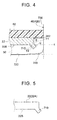
- FIG. 4 is a schematic view of the sealing structure on the positive electrode side, and is a sectional view taken along the direction of the hole axis of the through-hole 242.
- the gasket 50 is in contact with the bottom surface 22B of the lid 22 and provides sealing between the lid 22 and the positive-electrode collector terminal 40.
- the lid 22 has a protrusion 710 protruding obliquely downward from the bottom surface 22B.
- the protrusion 710 is provided so as to surround the through-hole 242 of the lid 22.
- the lid 22 and the collector terminal 40 compress and hold the gasket 50.
- the gasket 50 is appropriately pressed toward the collector terminal 40 and compressed at an area near the protrusion 710 of the lid 22.
- a horizontal surface 720 of the collector terminal 40 may be raised in the area near the protrusion 710 of the lid 22 to further enhance the sealability.
- the protrusion 710 is inclined toward a hole axis of the through-hole 242. That is, the protrusion 710 partially protrudes toward the hole axis of the through-hole 242, such that both side surfaces of the protrusion 710 are inclined toward the hole axis of the through-hole 242 in FIG. 4 .
- the conventional sealing structure has a protrusion protruding parallel to the hole axis direction of the through-hole, and thus has a gap between the gasket and the rounded surface located between the horizontal surface and the vertical surface (the side surface of the projection) of the collector terminal in some cases.
- the structure provided with the protrusion 710 inclined toward the hole axis of the through-hole 242 so as to partially protrude toward the hole axis of the through-hole 242 can prevent formation of a gap because stress is applied toward a rounded surface 740 located between the horizontal surface 720 and a vertical surface 730. This can maintain appropriate sealability between the collector terminal and the gasket over a long period of time (long-term sealability).
- the protrusion 710 is located at the edge of the lid 22 close to the through-hole 242, that is, located at the periphery of the through-hole 242, and the opening diameter of the through-hole 242 is smallest at the protrusion 710.
- Providing the protrusion 710 at the edge of the lid 22 close to the through-hole 242 can further reliably prevent the formation of a gap to enhance the long-term sealability.
- the protrusion 710 may be provided at any position at which the desired effect is achieved.
- the protrusion 710 may be provided at a position slightly offset from the edge (the periphery of the through-hole 242) in the direction away from the through-hole 242.
- an angle (acute angle) ⁇ defined by a reference line X extending along the bottom surface 22B of the lid 22 and an inclined surface Y1 of the protrusion 710, the inclined surface Y1 being close to the hole axis of the through-hole 242 (the inclined surface Y1 being located inward of an inclined surface Y2 of the protrusion 710 in the radial direction of the through-hole 242), is preferably within a range from 30° to 80°, and more preferably within a range from 40° to 70° (for example, within a range from approximately 45° to approximately 60°).
- the inclined surface Y2 of the protrusion 70 which is remote from the hole axis of the through-hole 242 (which is located outward of the inclined surface Y1 in the radial direction of the through-hole 242), is preferably more inclined toward the through-hole 242 than the inclined surface Y1 of the protrusion 710, which is close to the hole axis of the through-hole 242 (which is located inward of the inclined surface Y2 of the protrusion 710 in the radial direction of the through-hole 242).
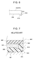
- the protrusion 710 inclined toward the direction of the hole axis of the through-hole 242 (toward the through-hole 242) is formed by, for example, preparing a lid preliminarily provided with a protrusion inclined toward the direction of the hole axis of the through-hole (toward the through-hole 242) as illustrated in FIG. 5 and riveting the projection 426 of the collector terminal 40.
- the lid 22 may be provided with a downward protrusion 810 protruding from the bottom surface 22B of the lid 22 as illustrated in FIG. 6 .
- the protrusion 810 has a surface 813 that is remote from the through-hole (that is located outward of the outer side surface of the protrusion 810 in the radial direction of the through-hole). At least a part of the surface 813 is tapered. Then, the projection 426 of the collector terminal 40 is riveted. During riveting, stress is applied in the thickness direction of the lid 22, and stress in the radial direction of the through-hole is generated in the protrusion 810 due to the tapered surface 813 of the protrusion 810. The generated stress may incline the protrusion 810 toward the through-hole (See the chain line in FIG. 6 ). The latter method is easier than the former method.
- the latter method makes it possible to easily form the protrusion 810 configured like the protrusion 710 in FIG. 4 formed such that the acute angle P defined by the reference line X and the inclined surface Y2 of the protrusion 710, which is remote from the hole axis of the through-hole 242, is smaller than the acute angle ⁇ ( ⁇ > P) as illustrated in FIG. 4 .
- the lithium-ion secondary battery 10 other than the protrusion 710 or 810 is fabricated by any commonly-employed method.
- the sectional shape of the protrusions 710, 810 is not limited to a rectangular shape.
- the protrusions 710, 810 may have any sectional shape, for example, a sectional shape including a curved line.
- the negative electrode of the battery 10 in the present embodiment has substantially the same structure as that of the positive electrode other than the material of the negative-electrode collector terminal 80. That is, the negative-electrode sheet 34 is connected to one end of the negative-electrode collector terminal 80 by, for example, resistance welding.
- the negative-electrode collector terminal 80 includes a negative-electrode inner terminal segment 820 having substantially the same shape as that of the positive-electrode inner terminal segment 420, a projection 826, and a negative-electrode outer terminal segment 860.
- the projection 826 is riveted to connect the negative-electrode inner terminal segment 820 to the negative-electrode outer terminal segment 860.
- the riveting is performed with a gasket 50, the lid 22, and an insulator 60 disposed between the negative-electrode inner terminal segment 820 and the negative-electrode outer terminal segment 860, as in the positive-electrode side.
- a protrusion is provided around the through-hole 244 of the lid 22, as in the positive-electrode side.
- the negative-electrode outer terminal segment 860 has a first connection portion and a second connection portion, and is formed in a stepwise manner.
- a bolt 670 is passed from below through a bolt-passing hole provided in the second connection portion.
- the negative-electrode inner terminal segment 820, the projection 826, and the negative-electrode outer terminal segment 860 are preferably made of a highly conductive metal, and are typically made of copper.
- the materials and shapes of the gasket 50 and the insulator 60 are the same as those in the positive-electrode side.
Landscapes
- Chemical & Material Sciences (AREA)
- Chemical Kinetics & Catalysis (AREA)
- Electrochemistry (AREA)
- General Chemical & Material Sciences (AREA)
- Engineering & Computer Science (AREA)
- Manufacturing & Machinery (AREA)
- Materials Engineering (AREA)
- Sealing Battery Cases Or Jackets (AREA)
- Connection Of Batteries Or Terminals (AREA)
- Electric Double-Layer Capacitors Or The Like (AREA)
Applications Claiming Priority (1)
| Application Number | Priority Date | Filing Date | Title |
|---|---|---|---|
| JP2015066864A JP6241676B2 (ja) | 2015-03-27 | 2015-03-27 | 密閉型電池 |
Publications (3)
| Publication Number | Publication Date |
|---|---|
| EP3073544A1 true EP3073544A1 (de) | 2016-09-28 |
| EP3073544B1 EP3073544B1 (de) | 2018-05-02 |
| EP3073544B8 EP3073544B8 (de) | 2018-08-15 |
Family
ID=55628883
Family Applications (1)
| Application Number | Title | Priority Date | Filing Date |
|---|---|---|---|
| EP16162188.3A Active EP3073544B8 (de) | 2015-03-27 | 2016-03-24 | Abgedichtete batterie |
Country Status (5)
| Country | Link |
|---|---|
| US (1) | US10062872B2 (de) |
| EP (1) | EP3073544B8 (de) |
| JP (1) | JP6241676B2 (de) |
| KR (1) | KR101841340B1 (de) |
| CN (1) | CN106025110B (de) |
Families Citing this family (7)
| Publication number | Priority date | Publication date | Assignee | Title |
|---|---|---|---|---|
| JP6601684B2 (ja) * | 2016-11-09 | 2019-11-06 | トヨタ自動車株式会社 | 密閉型電池および密閉型電池の製造方法 |
| KR102397762B1 (ko) * | 2017-06-01 | 2022-05-13 | 삼성에스디아이 주식회사 | 양극 단자 일체형 캡 플레이트를 갖는 이차 전지 |
| JP7001957B2 (ja) * | 2018-03-02 | 2022-01-20 | トヨタ自動車株式会社 | 電池の製造方法および電池 |
| JP7236035B2 (ja) * | 2019-12-04 | 2023-03-09 | トヨタ自動車株式会社 | 二次電池およびその製造方法 |
| CN111900452B (zh) * | 2020-06-24 | 2022-05-10 | 先进储能材料国家工程研究中心有限责任公司 | 垂直封口型圆柱电池及其制备方法 |
| CN115036134B (zh) * | 2022-07-18 | 2024-06-04 | 南通新江海动力电子有限公司 | 桥架结构及具有其的电容器 |
| CN220627988U (zh) * | 2023-08-04 | 2024-03-19 | 湖北亿纬动力有限公司 | 盖板组件、电池及电池包 |
Citations (8)
| Publication number | Priority date | Publication date | Assignee | Title |
|---|---|---|---|---|
| JPH08203494A (ja) | 1994-11-25 | 1996-08-09 | Sony Corp | 乾電池 |
| JP3573853B2 (ja) * | 1995-11-30 | 2004-10-06 | 三洋電機株式会社 | 密閉型電池 |
| JP2005339990A (ja) * | 2004-05-27 | 2005-12-08 | Toyota Motor Corp | 密閉型電池及び密閉型電池の製造方法 |
| EP2461393A1 (de) * | 2010-12-02 | 2012-06-06 | SB LiMotive Co., Ltd. | Wiederaufladbare Batterie |
| JP2012182070A (ja) | 2011-03-02 | 2012-09-20 | Toyota Motor Corp | 電池 |
| WO2014002819A1 (ja) * | 2012-06-29 | 2014-01-03 | トヨタ自動車株式会社 | 電池 |
| JP2014007119A (ja) | 2012-06-27 | 2014-01-16 | Toyota Motor Corp | 電池 |
| JP2014116139A (ja) | 2012-12-07 | 2014-06-26 | Toyota Motor Corp | 密閉型電池 |
Family Cites Families (1)
| Publication number | Priority date | Publication date | Assignee | Title |
|---|---|---|---|---|
| JP2009048969A (ja) * | 2007-08-23 | 2009-03-05 | Toyota Motor Corp | 電池 |
-
2015
- 2015-03-27 JP JP2015066864A patent/JP6241676B2/ja active Active
-
2016
- 2016-03-23 KR KR1020160034660A patent/KR101841340B1/ko active Active
- 2016-03-24 EP EP16162188.3A patent/EP3073544B8/de active Active
- 2016-03-25 CN CN201610179411.0A patent/CN106025110B/zh active Active
- 2016-03-25 US US15/081,086 patent/US10062872B2/en active Active
Patent Citations (9)
| Publication number | Priority date | Publication date | Assignee | Title |
|---|---|---|---|---|
| JPH08203494A (ja) | 1994-11-25 | 1996-08-09 | Sony Corp | 乾電池 |
| JP3573853B2 (ja) * | 1995-11-30 | 2004-10-06 | 三洋電機株式会社 | 密閉型電池 |
| JP2005339990A (ja) * | 2004-05-27 | 2005-12-08 | Toyota Motor Corp | 密閉型電池及び密閉型電池の製造方法 |
| EP2461393A1 (de) * | 2010-12-02 | 2012-06-06 | SB LiMotive Co., Ltd. | Wiederaufladbare Batterie |
| JP2012182070A (ja) | 2011-03-02 | 2012-09-20 | Toyota Motor Corp | 電池 |
| JP2014007119A (ja) | 2012-06-27 | 2014-01-16 | Toyota Motor Corp | 電池 |
| WO2014002819A1 (ja) * | 2012-06-29 | 2014-01-03 | トヨタ自動車株式会社 | 電池 |
| US20150180007A1 (en) * | 2012-06-29 | 2015-06-25 | Toyoko OHTA | Battery |
| JP2014116139A (ja) | 2012-12-07 | 2014-06-26 | Toyota Motor Corp | 密閉型電池 |
Also Published As
| Publication number | Publication date |
|---|---|
| US20160285058A1 (en) | 2016-09-29 |
| US10062872B2 (en) | 2018-08-28 |
| CN106025110A (zh) | 2016-10-12 |
| JP6241676B2 (ja) | 2017-12-06 |
| EP3073544B8 (de) | 2018-08-15 |
| JP2016186896A (ja) | 2016-10-27 |
| KR101841340B1 (ko) | 2018-03-22 |
| EP3073544B1 (de) | 2018-05-02 |
| CN106025110B (zh) | 2020-09-01 |
| KR20160115776A (ko) | 2016-10-06 |
Similar Documents
| Publication | Publication Date | Title |
|---|---|---|
| EP3073544B1 (de) | Abgedichtete batterie | |
| EP2613377B1 (de) | Batterieabdeckung mit daran befestigter elektrodenklemme, verfahren zur herstellung der batterieabdeckung mit daran befestigter elektrodenklemme und luftdichte batterie | |
| US10224533B2 (en) | Secondary battery comprising current interrupt device | |
| CN104641492B (zh) | 方形二次电池 | |
| JP4124756B2 (ja) | 密閉型電池 | |
| JP2009048968A (ja) | 密閉型電池 | |
| US9954216B2 (en) | Rectangular secondary battery | |
| CN104781946A (zh) | 四方形二次电池 | |
| US10224535B2 (en) | Rectangular secondary battery | |
| JPH11283588A (ja) | 密閉型電池 | |
| US11417874B2 (en) | Non-aqueous electrolyte secondary battery | |
| JP2009037817A (ja) | 電池 | |
| JP2002324541A (ja) | 密閉型電池 | |
| EP4167354A1 (de) | Sekundärbatterie | |
| US10243195B2 (en) | Nonaqueous electrolyte secondary battery | |
| JP4304924B2 (ja) | 電池 | |
| US12506202B2 (en) | Sealed battery | |
| JP2013196788A (ja) | 非水電解液二次電池 | |
| JP6837796B2 (ja) | 非水電解質二次電池 | |
| JP4984359B2 (ja) | 密閉型電池およびその封口板 | |
| JP2008305644A (ja) | 電池 | |
| JP2004030938A (ja) | 非水電解液二次電池 | |
| US20240154221A1 (en) | Cylindrical battery | |
| EP4170782A1 (de) | Sekundärbatterie | |
| JP4055395B2 (ja) | 密閉型電池 |
Legal Events
| Date | Code | Title | Description |
|---|---|---|---|
| PUAI | Public reference made under article 153(3) epc to a published international application that has entered the european phase |
Free format text: ORIGINAL CODE: 0009012 |
|
| 17P | Request for examination filed |
Effective date: 20160324 |
|
| AK | Designated contracting states |
Kind code of ref document: A1 Designated state(s): AL AT BE BG CH CY CZ DE DK EE ES FI FR GB GR HR HU IE IS IT LI LT LU LV MC MK MT NL NO PL PT RO RS SE SI SK SM TR |
|
| AX | Request for extension of the european patent |
Extension state: BA ME |
|
| RIN1 | Information on inventor provided before grant (corrected) |
Inventor name: HARAYAMA, TAKASHI |
|
| RAP1 | Party data changed (applicant data changed or rights of an application transferred) |
Owner name: TOYOTA JIDOSHA KABUSHIKI KAISHA |
|
| RIN1 | Information on inventor provided before grant (corrected) |
Inventor name: HARAYAMA, TAKASHI |
|
| GRAP | Despatch of communication of intention to grant a patent |
Free format text: ORIGINAL CODE: EPIDOSNIGR1 |
|
| STAA | Information on the status of an ep patent application or granted ep patent |
Free format text: STATUS: GRANT OF PATENT IS INTENDED |
|
| RIC1 | Information provided on ipc code assigned before grant |
Ipc: H01M 2/04 20060101AFI20170919BHEP Ipc: H01M 2/08 20060101ALN20170919BHEP Ipc: H01M 2/06 20060101ALI20170919BHEP Ipc: H01M 2/30 20060101ALN20170919BHEP Ipc: H01M 2/22 20060101ALI20170919BHEP |
|
| INTG | Intention to grant announced |
Effective date: 20171017 |
|
| GRAS | Grant fee paid |
Free format text: ORIGINAL CODE: EPIDOSNIGR3 |
|
| GRAA | (expected) grant |
Free format text: ORIGINAL CODE: 0009210 |
|
| STAA | Information on the status of an ep patent application or granted ep patent |
Free format text: STATUS: THE PATENT HAS BEEN GRANTED |
|
| RIN1 | Information on inventor provided before grant (corrected) |
Inventor name: HARAYAMA, TAKASHI |
|
| RAP1 | Party data changed (applicant data changed or rights of an application transferred) |
Owner name: TOYOTA JIDOSHA KABUSHIKI KAISHA |
|
| AK | Designated contracting states |
Kind code of ref document: B1 Designated state(s): AL AT BE BG CH CY CZ DE DK EE ES FI FR GB GR HR HU IE IS IT LI LT LU LV MC MK MT NL NO PL PT RO RS SE SI SK SM TR |
|
| REG | Reference to a national code |
Ref country code: GB Ref legal event code: FG4D |
|
| REG | Reference to a national code |
Ref country code: CH Ref legal event code: EP Ref country code: AT Ref legal event code: REF Ref document number: 996174 Country of ref document: AT Kind code of ref document: T Effective date: 20180515 |
|
| REG | Reference to a national code |
Ref country code: DE Ref legal event code: R096 Ref document number: 602016002700 Country of ref document: DE Ref country code: IE Ref legal event code: FG4D |
|
| RIN2 | Information on inventor provided after grant (corrected) |
Inventor name: HARAYAMA, TAKASHI |
|
| REG | Reference to a national code |
Ref country code: CH Ref legal event code: PK Free format text: BERICHTIGUNG B8 |
|
| RIN2 | Information on inventor provided after grant (corrected) |
Inventor name: HARAYAMA, TAKASHI |
|
| REG | Reference to a national code |
Ref country code: NL Ref legal event code: MP Effective date: 20180502 |
|
| REG | Reference to a national code |
Ref country code: CH Ref legal event code: PK Free format text: BERICHTIGUNGEN |
|
| REG | Reference to a national code |
Ref country code: LT Ref legal event code: MG4D |
|
| REG | Reference to a national code |
Ref country code: DE Ref legal event code: R084 Ref document number: 602016002700 Country of ref document: DE |
|
| RIN2 | Information on inventor provided after grant (corrected) |
Inventor name: HARAYAMA, TAKASHI |
|
| REG | Reference to a national code |
Ref country code: GB Ref legal event code: 746 Effective date: 20180928 |
|
| PG25 | Lapsed in a contracting state [announced via postgrant information from national office to epo] |
Ref country code: FI Free format text: LAPSE BECAUSE OF FAILURE TO SUBMIT A TRANSLATION OF THE DESCRIPTION OR TO PAY THE FEE WITHIN THE PRESCRIBED TIME-LIMIT Effective date: 20180502 Ref country code: BG Free format text: LAPSE BECAUSE OF FAILURE TO SUBMIT A TRANSLATION OF THE DESCRIPTION OR TO PAY THE FEE WITHIN THE PRESCRIBED TIME-LIMIT Effective date: 20180802 Ref country code: NO Free format text: LAPSE BECAUSE OF FAILURE TO SUBMIT A TRANSLATION OF THE DESCRIPTION OR TO PAY THE FEE WITHIN THE PRESCRIBED TIME-LIMIT Effective date: 20180802 Ref country code: ES Free format text: LAPSE BECAUSE OF FAILURE TO SUBMIT A TRANSLATION OF THE DESCRIPTION OR TO PAY THE FEE WITHIN THE PRESCRIBED TIME-LIMIT Effective date: 20180502 Ref country code: SE Free format text: LAPSE BECAUSE OF FAILURE TO SUBMIT A TRANSLATION OF THE DESCRIPTION OR TO PAY THE FEE WITHIN THE PRESCRIBED TIME-LIMIT Effective date: 20180502 Ref country code: LT Free format text: LAPSE BECAUSE OF FAILURE TO SUBMIT A TRANSLATION OF THE DESCRIPTION OR TO PAY THE FEE WITHIN THE PRESCRIBED TIME-LIMIT Effective date: 20180502 |
|
| PG25 | Lapsed in a contracting state [announced via postgrant information from national office to epo] |
Ref country code: LV Free format text: LAPSE BECAUSE OF FAILURE TO SUBMIT A TRANSLATION OF THE DESCRIPTION OR TO PAY THE FEE WITHIN THE PRESCRIBED TIME-LIMIT Effective date: 20180502 Ref country code: RS Free format text: LAPSE BECAUSE OF FAILURE TO SUBMIT A TRANSLATION OF THE DESCRIPTION OR TO PAY THE FEE WITHIN THE PRESCRIBED TIME-LIMIT Effective date: 20180502 Ref country code: NL Free format text: LAPSE BECAUSE OF FAILURE TO SUBMIT A TRANSLATION OF THE DESCRIPTION OR TO PAY THE FEE WITHIN THE PRESCRIBED TIME-LIMIT Effective date: 20180502 Ref country code: HR Free format text: LAPSE BECAUSE OF FAILURE TO SUBMIT A TRANSLATION OF THE DESCRIPTION OR TO PAY THE FEE WITHIN THE PRESCRIBED TIME-LIMIT Effective date: 20180502 Ref country code: GR Free format text: LAPSE BECAUSE OF FAILURE TO SUBMIT A TRANSLATION OF THE DESCRIPTION OR TO PAY THE FEE WITHIN THE PRESCRIBED TIME-LIMIT Effective date: 20180803 |
|
| REG | Reference to a national code |
Ref country code: AT Ref legal event code: MK05 Ref document number: 996174 Country of ref document: AT Kind code of ref document: T Effective date: 20180502 |
|
| PG25 | Lapsed in a contracting state [announced via postgrant information from national office to epo] |
Ref country code: EE Free format text: LAPSE BECAUSE OF FAILURE TO SUBMIT A TRANSLATION OF THE DESCRIPTION OR TO PAY THE FEE WITHIN THE PRESCRIBED TIME-LIMIT Effective date: 20180502 Ref country code: PL Free format text: LAPSE BECAUSE OF FAILURE TO SUBMIT A TRANSLATION OF THE DESCRIPTION OR TO PAY THE FEE WITHIN THE PRESCRIBED TIME-LIMIT Effective date: 20180502 Ref country code: AT Free format text: LAPSE BECAUSE OF FAILURE TO SUBMIT A TRANSLATION OF THE DESCRIPTION OR TO PAY THE FEE WITHIN THE PRESCRIBED TIME-LIMIT Effective date: 20180502 Ref country code: RO Free format text: LAPSE BECAUSE OF FAILURE TO SUBMIT A TRANSLATION OF THE DESCRIPTION OR TO PAY THE FEE WITHIN THE PRESCRIBED TIME-LIMIT Effective date: 20180502 Ref country code: CZ Free format text: LAPSE BECAUSE OF FAILURE TO SUBMIT A TRANSLATION OF THE DESCRIPTION OR TO PAY THE FEE WITHIN THE PRESCRIBED TIME-LIMIT Effective date: 20180502 Ref country code: SK Free format text: LAPSE BECAUSE OF FAILURE TO SUBMIT A TRANSLATION OF THE DESCRIPTION OR TO PAY THE FEE WITHIN THE PRESCRIBED TIME-LIMIT Effective date: 20180502 Ref country code: DK Free format text: LAPSE BECAUSE OF FAILURE TO SUBMIT A TRANSLATION OF THE DESCRIPTION OR TO PAY THE FEE WITHIN THE PRESCRIBED TIME-LIMIT Effective date: 20180502 |
|
| REG | Reference to a national code |
Ref country code: DE Ref legal event code: R097 Ref document number: 602016002700 Country of ref document: DE |
|
| PG25 | Lapsed in a contracting state [announced via postgrant information from national office to epo] |
Ref country code: SM Free format text: LAPSE BECAUSE OF FAILURE TO SUBMIT A TRANSLATION OF THE DESCRIPTION OR TO PAY THE FEE WITHIN THE PRESCRIBED TIME-LIMIT Effective date: 20180502 Ref country code: IT Free format text: LAPSE BECAUSE OF FAILURE TO SUBMIT A TRANSLATION OF THE DESCRIPTION OR TO PAY THE FEE WITHIN THE PRESCRIBED TIME-LIMIT Effective date: 20180502 |
|
| PLBE | No opposition filed within time limit |
Free format text: ORIGINAL CODE: 0009261 |
|
| STAA | Information on the status of an ep patent application or granted ep patent |
Free format text: STATUS: NO OPPOSITION FILED WITHIN TIME LIMIT |
|
| 26N | No opposition filed |
Effective date: 20190205 |
|
| PG25 | Lapsed in a contracting state [announced via postgrant information from national office to epo] |
Ref country code: SI Free format text: LAPSE BECAUSE OF FAILURE TO SUBMIT A TRANSLATION OF THE DESCRIPTION OR TO PAY THE FEE WITHIN THE PRESCRIBED TIME-LIMIT Effective date: 20180502 |
|
| PG25 | Lapsed in a contracting state [announced via postgrant information from national office to epo] |
Ref country code: MC Free format text: LAPSE BECAUSE OF FAILURE TO SUBMIT A TRANSLATION OF THE DESCRIPTION OR TO PAY THE FEE WITHIN THE PRESCRIBED TIME-LIMIT Effective date: 20180502 |
|
| REG | Reference to a national code |
Ref country code: CH Ref legal event code: PL |
|
| PG25 | Lapsed in a contracting state [announced via postgrant information from national office to epo] |
Ref country code: LU Free format text: LAPSE BECAUSE OF NON-PAYMENT OF DUE FEES Effective date: 20190324 Ref country code: AL Free format text: LAPSE BECAUSE OF FAILURE TO SUBMIT A TRANSLATION OF THE DESCRIPTION OR TO PAY THE FEE WITHIN THE PRESCRIBED TIME-LIMIT Effective date: 20180502 |
|
| REG | Reference to a national code |
Ref country code: BE Ref legal event code: MM Effective date: 20190331 |
|
| PG25 | Lapsed in a contracting state [announced via postgrant information from national office to epo] |
Ref country code: CH Free format text: LAPSE BECAUSE OF NON-PAYMENT OF DUE FEES Effective date: 20190331 Ref country code: IE Free format text: LAPSE BECAUSE OF NON-PAYMENT OF DUE FEES Effective date: 20190324 Ref country code: LI Free format text: LAPSE BECAUSE OF NON-PAYMENT OF DUE FEES Effective date: 20190331 |
|
| PG25 | Lapsed in a contracting state [announced via postgrant information from national office to epo] |
Ref country code: BE Free format text: LAPSE BECAUSE OF NON-PAYMENT OF DUE FEES Effective date: 20190331 |
|
| PG25 | Lapsed in a contracting state [announced via postgrant information from national office to epo] |
Ref country code: TR Free format text: LAPSE BECAUSE OF FAILURE TO SUBMIT A TRANSLATION OF THE DESCRIPTION OR TO PAY THE FEE WITHIN THE PRESCRIBED TIME-LIMIT Effective date: 20180502 |
|
| PG25 | Lapsed in a contracting state [announced via postgrant information from national office to epo] |
Ref country code: MT Free format text: LAPSE BECAUSE OF NON-PAYMENT OF DUE FEES Effective date: 20190324 Ref country code: PT Free format text: LAPSE BECAUSE OF FAILURE TO SUBMIT A TRANSLATION OF THE DESCRIPTION OR TO PAY THE FEE WITHIN THE PRESCRIBED TIME-LIMIT Effective date: 20180903 |
|
| REG | Reference to a national code |
Ref country code: DE Ref legal event code: R079 Ref document number: 602016002700 Country of ref document: DE Free format text: PREVIOUS MAIN CLASS: H01M0002040000 Ipc: H01M0050147000 |
|
| PG25 | Lapsed in a contracting state [announced via postgrant information from national office to epo] |
Ref country code: CY Free format text: LAPSE BECAUSE OF FAILURE TO SUBMIT A TRANSLATION OF THE DESCRIPTION OR TO PAY THE FEE WITHIN THE PRESCRIBED TIME-LIMIT Effective date: 20180502 |
|
| PG25 | Lapsed in a contracting state [announced via postgrant information from national office to epo] |
Ref country code: IS Free format text: LAPSE BECAUSE OF FAILURE TO SUBMIT A TRANSLATION OF THE DESCRIPTION OR TO PAY THE FEE WITHIN THE PRESCRIBED TIME-LIMIT Effective date: 20180902 |
|
| PG25 | Lapsed in a contracting state [announced via postgrant information from national office to epo] |
Ref country code: HU Free format text: LAPSE BECAUSE OF FAILURE TO SUBMIT A TRANSLATION OF THE DESCRIPTION OR TO PAY THE FEE WITHIN THE PRESCRIBED TIME-LIMIT; INVALID AB INITIO Effective date: 20160324 |
|
| PG25 | Lapsed in a contracting state [announced via postgrant information from national office to epo] |
Ref country code: MK Free format text: LAPSE BECAUSE OF FAILURE TO SUBMIT A TRANSLATION OF THE DESCRIPTION OR TO PAY THE FEE WITHIN THE PRESCRIBED TIME-LIMIT Effective date: 20180502 |
|
| P01 | Opt-out of the competence of the unified patent court (upc) registered |
Effective date: 20230427 |
|
| PGFP | Annual fee paid to national office [announced via postgrant information from national office to epo] |
Ref country code: GB Payment date: 20260202 Year of fee payment: 11 |
|
| PGFP | Annual fee paid to national office [announced via postgrant information from national office to epo] |
Ref country code: DE Payment date: 20260128 Year of fee payment: 11 |
|
| PGFP | Annual fee paid to national office [announced via postgrant information from national office to epo] |
Ref country code: FR Payment date: 20260209 Year of fee payment: 11 |