EP3073761A1 - Haut-parleur - Google Patents
Haut-parleur Download PDFInfo
- Publication number
- EP3073761A1 EP3073761A1 EP16161140.5A EP16161140A EP3073761A1 EP 3073761 A1 EP3073761 A1 EP 3073761A1 EP 16161140 A EP16161140 A EP 16161140A EP 3073761 A1 EP3073761 A1 EP 3073761A1
- Authority
- EP
- European Patent Office
- Prior art keywords
- loudspeaker
- front wall
- sound
- housing
- wall
- Prior art date
- Legal status (The legal status is an assumption and is not a legal conclusion. Google has not performed a legal analysis and makes no representation as to the accuracy of the status listed.)
- Withdrawn
Links
Images


Classifications
-
- H—ELECTRICITY
- H04—ELECTRIC COMMUNICATION TECHNIQUE
- H04R—LOUDSPEAKERS, MICROPHONES, GRAMOPHONE PICK-UPS OR LIKE ACOUSTIC ELECTROMECHANICAL TRANSDUCERS; ELECTRIC HEARING AIDS; PUBLIC ADDRESS SYSTEMS
- H04R1/00—Details of transducers, loudspeakers or microphones
- H04R1/20—Arrangements for obtaining desired frequency or directional characteristics
- H04R1/22—Arrangements for obtaining desired frequency or directional characteristics for obtaining desired frequency characteristic only
- H04R1/28—Transducer mountings or enclosures modified by provision of mechanical or acoustic impedances, e.g. resonator, damping means
- H04R1/2807—Enclosures comprising vibrating or resonating arrangements
- H04R1/283—Enclosures comprising vibrating or resonating arrangements using a passive diaphragm
- H04R1/2834—Enclosures comprising vibrating or resonating arrangements using a passive diaphragm for loudspeaker transducers
-
- H—ELECTRICITY
- H04—ELECTRIC COMMUNICATION TECHNIQUE
- H04R—LOUDSPEAKERS, MICROPHONES, GRAMOPHONE PICK-UPS OR LIKE ACOUSTIC ELECTROMECHANICAL TRANSDUCERS; ELECTRIC HEARING AIDS; PUBLIC ADDRESS SYSTEMS
- H04R2201/00—Details of transducers, loudspeakers or microphones covered by H04R1/00 but not provided for in any of its subgroups
- H04R2201/02—Details casings, cabinets or mounting therein for transducers covered by H04R1/02 but not provided for in any of its subgroups
- H04R2201/021—Transducers or their casings adapted for mounting in or to a wall or ceiling
-
- H—ELECTRICITY
- H04—ELECTRIC COMMUNICATION TECHNIQUE
- H04R—LOUDSPEAKERS, MICROPHONES, GRAMOPHONE PICK-UPS OR LIKE ACOUSTIC ELECTROMECHANICAL TRANSDUCERS; ELECTRIC HEARING AIDS; PUBLIC ADDRESS SYSTEMS
- H04R2440/00—Bending wave transducers covered by H04R, not provided for in its groups
Definitions
- the present invention relates to a loudspeaker having a housing and a first sound generator. Moreover, the present invention relates to a vibration diaphragm for a loudspeaker.
- Loudspeakers themselves are known in the art. The structure and underlying technology should therefore not be discussed in detail here. Loudspeakers contain so-called sound generators, which are usually equipped with a vibration membrane in order to deliver the sound waves generated by the sound generator to the surrounding medium (air). Such sound generators exist for the low, mid, and high frequency ranges, with the frequency range of music perceptibility ranging from about 40 Hz to about 8,000 kHz.
- a loudspeaker sound generators can each be accommodated with a vibration diaphragm in a suitable loudspeaker box.
- a subwoofer basic box
- a list of such subwoofer in any place in the room is possible.
- the largest possible amount of air has to be moved, for which subwoofers either use a sound generator with the largest possible membrane area or else one Insert sound generator whose membrane surface can be deflected with large amplitude.
- the signal is supplied to a subwoofer via a loudspeaker switch, which filters the low-frequency components from the signals for the sound generators and then forwards them to the sound generator of the subwoofer, while the other components are forwarded to the remaining sound generators.
- exciters are known that represent membraneless sound generators. They use a solid object as a "membrane", for which purpose an exciter is fixed to such an object that it vibrates. Such exciters are mainly used in the field of sound furniture. For example, they can be stuck under tables, in cabinets, in ceilings, etc., thus acting as an invisible loudspeaker.
- Subwoofers are often large, unwieldy devices that require a lot of space. Separated from the subwoofers, high and midrange speakers must be placed in the room. This usually involves long cable runs. Wireless systems have not worked without sacrificing transmission and / or listening quality.
- the sound quality of furniture with directly attached exciters depends strongly on the surface, the geometry as well as the structure and the material of the respective furniture. In particular, bonding, gluing, joints, etc. disturb the sound propagation and have a strong effect on the sound quality.
- the DE 44 46 690 A1 to reduce the previously necessary subwoofer housing volume before a speaker assembly before, in the two Speakers are connected in series in a common housing.
- a speaker for the entire frequency range In the front wall of the housing is a speaker for the entire frequency range, while in a partition wall of the housing, a speaker for low frequencies is arranged.
- the rear wall of the housing In the rear wall of the housing, for example, there is a sound opening.
- the loudspeaker for low frequency range reproduction in the middle and high frequency ranges acts as a passive radiator of the loudspeaker for the entire frequency range reproduction.
- the reproduced sound pressure level in the low frequency range is increased and smoothed by the proposed arrangement there.
- the sound opening in the back of the housing can be replaced by another passive radiator, which can represent a resiliently inserted into the rear wall of the housing wall or a vibration membrane used there. This leads to a further improvement of the characteristic in the low frequency range.
- a loudspeaker is formed by a loudspeaker housing, which is divided by an intermediate wall into two cavities.
- the intermediate wall has a driver connected in series with a passive radiator in the front of the housing so that the sound producing side of the driver and the passive radiator face in the same direction.
- the passive radiator is designed as a flat rectangular passive radiator, ie as a flat rectangular membrane, which is inserted into the front wall of the housing.
- Passive radiators thus form in a housing wall or in an intermediate wall within the housing of a loudspeaker vibrationally decoupled sound generator or vibration diaphragm, which are set in vibration by a sound generator acting as a driver.
- Such passive radiators have in the presently considered particular use of a speaker as a sound furniture the disadvantage that a mounted in a visible front wall of the speaker housing passive radiator reduces the stability of the housing front wall.
- the part of the front wall that forms the passive radiator is mechanically less resilient and sensitive to pressure, shock or the like. In addition, this is in certain uses of sound furniture aesthetic disadvantages.
- An inventive loudspeaker has a housing and (at least) a first sound generator, wherein the first sound generator is mounted in a mounting wall and limits this mounting wall with a front side wall of the housing spaced apart on a sound-generating side of the first sound generator and an airtight space.
- the front wall forms a vibration diaphragm of the loudspeaker, which is rigidly connected to the housing of the loudspeaker.
- the first sound generator may also be referred to as an airborne sound transducer.
- the mounting wall and the front wall of the speaker may be substantially parallel to each other. Both walls define an airtight space, which is bounded on the other sides in particular by the housing of the speaker.
- the (first) sound generator is held by the mounting wall and, in particular via its own vibration membrane from sound waves in the hermetically sealed space. The sound waves propagate to the front wall of the housing and vibrate them in turn, so that the front wall (or at least part of this front wall) the vibration membrane of the speaker.
- the sound-transmitting surface can be increased by a factor corresponding to the ratio of the area of the vibration diaphragm of the loudspeaker formed by the front wall to the surface of the vibration diaphragm of the sound generator.
- the effective area of the vibrating diaphragm of the loudspeaker can be increased many times as compared with the actual area of the sound generator vibrating diaphragm, whereby a much better sound quality can be achieved especially in the low frequency range than with known solutions of the prior art.
- the vibration membrane of the speaker forming part of the front wall of the housing with the housing is rigid or rigid.
- this is not a vibration-decoupled attachment. Rather, forms the part of the front wall functioning as a vibration diaphragm of the speaker together with the front wall a solid surface, it being particularly advantageous if the entire front wall of the housing of the speaker forms the vibration membrane.
- the acting as a vibration member part of the front wall is frictionally, material and / or positively connected to the rest of the housing or may also be made in one piece. A cohesive connection, in particular by gluing, has proved to be particularly advantageous.
- the front wall of the housing a one-piece solid surface that is rigidly and rigidly connected to the rest of the housing.
- the entire front wall can serve as a vibration diaphragm of the speaker.
- the housing then forms a stable composite together with the front wall, so that the loudspeaker according to the invention can be used in a particularly suitable manner as sound furniture.
- the entire front wall of the vibration membrane of Speaker forms.
- the front side of the loudspeaker according to the invention used as sound furniture thus transmits the sound into the room.
- the sound quality is many times higher, because not an exciter directly sets the front of the housing in vibration, but a relatively small speaker (sound generator with vibration membrane in the mounting wall) the sound waves over the hermetically sealed space transfers to the large area of the front wall.
- this front wall simultaneously forms the vibration diaphragm of the loudspeaker and part of the furniture, such as a panel, an image, a wall unit, a sliding door or the like.
- said factor ie the ratio of the area of the vibration membrane formed by the front wall (or at least a part thereof) to the surface of the actual sound generator vibration membrane, is at least 2.0, more particularly 4.0 or 5.0 or 10 or 20 to about 25 or 30. In particular, ratios of 4 to 10 are preferred. Due to the fact that both oscillating surfaces are coupled via the airtight space, it is possible according to the invention to achieve a high magnification of the surface which effectively transmits sound to the surroundings.
- the front wall is, as will be explained below (at least in part) made of a suitable material capable of vibrating. It is advantageous if the entire front wall or at least the largest part of the front wall forms the vibration diaphragm of the loudspeaker according to the invention.
- the first sound generator mounted in the mounting wall is, in particular, an airborne sound transducer (woofer) for generating sound frequencies in a first frequency range, in particular in the range from 25 Hz to 600 Hz.
- an airborne sound transducer woofer
- the first sound generator mounted in the mounting wall emits sound waves only to the airtight space without vibrating the mounting wall itself (vibration-decoupled connection).
- the sound generator can be accommodated swinging in the mounting wall and indeed in such a way that as little vibration as possible is transmitted to the mounting wall itself.
- the holder made of a first material
- the holder can be integrated into a mounting wall (made of a second rigid material).
- a one-piece design is also possible, wherein the mounting wall has a comparatively high material thickness, in particular in comparison to the front wall, so that it is hardly vibrated.
- the vibration membrane forming part of the front wall of the speaker is made of a mineral material.
- mineral materials are mineral-organic composites, as they are for example under the name Corian on the market.
- Corian consists of about 66 wt .-% of a modification of aluminum hydroxide and about 33 wt .-% of polymethyl methacrylate (PMMA) and of catalysts and other curing agents.
- PMMA polymethyl methacrylate
- a mineral material used herein may contain about 40% ( ⁇ 10%) ground stone or marble and about 60% ( ⁇ 10%) acrylic. Externally, the material resembles marble, but is lighter, can be cut and cut, but also thermally deformed three-dimensionally.
- the housing of the speaker has a rear wall which lies on the side facing away from the front wall of the mounting wall and spaced from this mounting wall. Again, in particular the rear wall and mounting wall are substantially parallel to each other.
- the housing has a back wall and a front wall, wherein the mounting wall is located as an intermediate wall in the interior of the housing.
- second sound generators each have a sound-generating side connected in a sound conducting manner to the front wall of the housing.
- These second sound generators are in particular exciters already discussed in the introduction to the introduction of sound frequencies in a second frequency range.
- This second frequency range in particular, adjoins or overlaps the first frequency range and in particular ranges from 500 Hz to 20,000 Hz.
- Such exciters can sound conducting in a simple manner (for example, by gluing) with the front wall of the housing, so the vibration of the speaker according to the invention, are connected.
- An even number of exciters, in particular two or four exciters, has proven to be particularly advantageous.
- a material reinforcement located on the front wall extends between two of the second sound generators.
- the material reinforcement therefore extends in particular between two sound generators, so that the material reinforcement divides the front wall into two parts, in each of which two second sound generators are located.
- the material reinforcement causes a channel separation, which leads to the known stereo effect.
- the material reinforcement extends between two opposite sides of the front wall.
- the material reinforcement (s) in this case should divide the front wall approximately in equal parts of the surface.
- the material reinforcement with one of these opposite sides an angle of 80 ° to 90 °, in particular from 80 ° to 85 °, more particularly about 85 °, includes. This results in a rectangular front wall trapezoidal surface parts. This slight asymmetry causes natural frequencies to be effectively suppressed.
- the material reinforcement forms in particular a web or a web-like material reinforcement. It has proven to be advantageous if the web decreases in its dimension perpendicular to the front in each case to its two ends. This can be achieved in particular in that the web has a circular arc-shaped cross-section in the longitudinal direction. Such shaped webs cause a tontechnisch favorable channel separation, especially for the frequency range above 1,000 Hz.
- the material reinforcement is formed in particular by the rear of the front wall of the housing in particular perpendicular to the front wall surfaces. These surfaces may be part of a box or shelf system, for example, wherein the leading edges of this system can be glued or glued to the front wall of the speaker housing. This embodiment will be explained in more detail below in an embodiment of the invention.
- the front wall may have a rectangular shape with a longitudinal side of 1,000 to 1,500 mm and a width of 600 to 800 mm.
- the entire front wall can serve here as a vibration diaphragm of the speaker for the frequency range below 600 Hz.
- An imaginary line runs perpendicular to the middle of the long side, so that this imaginary line divides the front wall into two equal-sized surface parts. Instead of an angle of 90 ° this line is now tilted to about 85 ° (to about 80 °).
- a separating web is now applied to the side of the front wall facing the interior of the housing (for example by gluing).
- An even number, in particular two exciters are slightly offset from each other, approximately centrally, mounted on the inner sides of the surface parts of the front wall (for example, glued).
- the separation web mentioned acts tonally as channel separation, since vibrations of the right surface part can not reach the left surface part and vice versa.
- An airborne transducer or woofer is embedded in a mounting wall substantially vibration decoupled, said mounting wall forms an airtight space together with the front wall and the housing of the speaker.
- Front wall and mounting wall in particular run parallel to each other. The clear distance between the two walls is 3 to 8, in particular 5 mm.
- an aluminum plate can be used, which is as low as possible or stiff, so the sound does not transmit or record.
- a solid surface plate can serve as a mounting wall, this plate is preferably about 4 to 5 times as strong as serving as the vibration membrane of the speaker solid surface front wall.
- the latter may preferably be between about 2 and 4 mm thick.
- the vibration decoupling is achieved by suitable fastening means.
- the airborne transducer or woofer is preferably positioned centrally and below the connecting lines of the respective exciter in the left and right surface part of the front wall.
- the area of the front wall of such a loudspeaker serving as a vibration membrane may be about 10 to 30 times larger than the small area of the vibration membrane of the airborne transducer or woofer. Due to the airtight space, the vibration of the airborne transducer or woofer is optimally transmitted to the front wall.
- the above example of a speaker according to the invention illustrates its suitability as a sound furniture.
- the serving as a vibration membrane front wall is sufficiently stable, since the front wall can have sufficient material thickness.
- This is a great advantage over vibration membranes or passive radiators according to the prior art, which are often less than 1 mm in thickness and are mounted resiliently in the housing.
- Such material thicknesses or resilient housing parts would be less suitable for use as furniture due to their low load capacity.
- the loudspeaker described above by way of example may have a rear wall which is at a distance from the mounting wall, wherein the distance may be in particular 30 to 60 mm. Overall, this creates a panel that can serve as an image or wall element, for example.
- a vibration diaphragm for a loudspeaker wherein the vibration diaphragm is made of a solid surface material.
- the properties of mineral materials and examples of such mineral materials are given above and discussed in detail. Surprisingly, it has been found that such mineral materials are also suitable as a vibration membrane with sufficiently low material thickness. In particular, use in sound furniture is advantageous here.
- the material thickness should be between 1 mm and 5 mm, in particular 2 to 4 mm, in particular 3 mm. Due to the homogeneity and gap-free nature of mineral composite panels, they are optimally suited as a vibration membrane.
- FIG. 1 schematically shows the most essential elements of a loudspeaker 1 according to the invention with its front wall 6 in a view, so that the elements located behind the front wall 6 are visible.
- a total of four exciters 10, 11 and 13, 14 are attached as second sound generators.
- the front wall 6 of the speaker 1 forms a rectangle.
- a separation web 12 is arranged approximately in the middle of the longitudinal side of the rectangle, wherein the separation web 12 is not at a right angle to the longitudinal side, but is inclined at an angle of about 85 ° to the longitudinal side. In this way, the surface of the front wall 6 is divided into approximately two equal parts of the surface.
- the separation web 12 extends on the rear side of the front wall 6 and is used in sound engineering channel separation.
- the separation web 12 has a circular arc-shaped cross-section in the longitudinal direction, so that its dimensions decrease perpendicular to the front wall in each case towards its two ends or respectively to the two longitudinal sides of the front wall 6.
- the web 12 is made of the same material as the front wall and is glued to this or connected by a thermal joining method with this. Such a divider 12 leads to an optimal damping of frequencies from one surface part towards the other surface part of the front wall 6.
- the first sound generator recognizable which is here an airborne sound transducer, hereinafter referred to as woofer 3, is.
- This woofer 3 has its own vibration membrane 4. Projected on the plane of the FIG. 1 the woofer 3 is below the connecting line of the exciter 10 and 13 and slightly below the connecting line of the exciter 11 and 14. It has been shown that this arrangement is particularly favorable for the sound quality.
- the woofer 3 is in turn not arranged on the front wall 6, but on a separate mounting wall 5, as based on FIG. 2 is explained.
- FIG. 1 also shown is a crossover network 9, which filters the low-frequency components from a (sound) signal and feeds them to the woofer 3, while the remaining components are supplied to the exciters 10, 11 and 13, 14.
- FIG. 1 It can be seen that the area of the front wall 6, here the loudspeaker vibration diaphragm 6 ', which is about 30 times the area of the woofer vibration membrane 4, so that the sound-emitting surface according to the invention can be increased by a multiple.
- FIG. 2 shows a cross section of the speaker 1 from FIG. 1 along the dashed line AA in FIG. 1 ,
- the speaker 1 has a housing 2.
- the front wall is again denoted by 6.
- the exciters 10 and 11 are shown schematically in cross section.
- the woofer 3 is supported by a mounting wall 5 such that as possible no vibration is transmitted to the mounting wall 5.
- the mounting wall 5 also with correspondingly higher Material thickness and / or be made of a corresponding material.
- the woofer 3 outputs vibrations of low frequency, in particular between 25 and 600 Hz via the vibration diaphragm 4 to the airtight space 7 from.
- the space 7 is filled with air in this example. Other fluids, in particular gases for filling the space 7 are conceivable.
- the airtight space 7 is formed by the front wall 6, the mounting wall 5 and the rest of the housing 2. Behind the mounting wall 5, a rear wall 8 is arranged, which is part of the housing 2.
- a speaker 1 shown here is particularly well suited as sound furniture or as part of a piece of furniture, for example as a panel or as part of a counter, a door or a wall. With a somewhat less deep design, the speaker 1 can also be used as an image when the front wall 6 is painted or printed.
- the material of the front wall 6 of the mineral material Corian at a thickness of about 2 to 4 mm.
- the material of the mounting wall 5 is an aluminum plate or also a solid surface plate offers. For possible dimensions, please refer to the above.
- FIG. 3 A further embodiment of a loudspeaker 1 according to the invention is shown in FIG. 3 shown. Like elements are again denoted by the same reference numerals as in the previous figures and therefore will not be explained again in detail.
- FIG. 3 illustrated embodiment is particularly suitable as a panel or as a picture in the form of a sound cabinet.
- the exciters 10 and 11 are shown, which are applied directly on the inside of the front wall of the loudspeaker 1. These exciters are located in the airtight space 7.
- the sound generator 3 is held by both the mounting wall 5 and the rear wall 8 of the speaker 1.
- the sound generator 3 is in turn supported in the mounting wall in such a way that as far as possible no vibration is transmitted to the mounting wall 5.
- the sound generated by the sound generator 3 can be optimally transmitted through the airtight space 7 to the front wall 6 of the loudspeaker 1, which forms the loudspeaker vibration diaphragm 6 '.
- the sound furniture formed by the speaker 1 can be fixed, for example via the rear wall 8 to a wall.
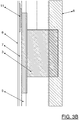
- FIG. 3B shows a detail view of in FIG. 3A circled area of the speaker 1 according to the invention to the sound generator 3, so the woofer, around.
- the existing of solid surface front wall 6 has a thickness of 3mm.
- the air chamber or the air-tight space 7 has a depth of 5mm.
- the mounting wall 5 may for example have a thickness of 13mm and also be made of mineral material.
- the woofer 3 is anchored in this embodiment in the rear wall 8 of the housing and is additionally supported by the mounting wall 5.
- FIG. 4 shows a third embodiment of a speaker 1 with a housing 2, which is only partially shown. Again, the drawing is not necessarily true to scale. Shown is the front wall 6 of the speaker 1, applied to the back of the second sound generator exciter 10, 11, 13, 14, 15 and 16, in particular glued. The surface of the front wall is divided into three parts by means of a box-like structure 17. The box structure 17 becomes, for example glued or glued to the rear side of the front wall 6, or more generally expressed, materially connected. In this way, the three resulting parts of the front wall 6 are acoustically or acoustically decoupled from each other. The three exciters 10, 11 and 16 are here in the left part of the front wall 6 according to FIG.
- the middle part of the front wall 6 in this embodiment forms the loudspeaker vibration diaphragm 6 '.
- the first sound generator 3, here the woofer can be mounted vibration-decoupled in a rear wall of the box structure 17 and / or in a rear wall of the housing 2 (cf. the embodiments according to FIG Figures 2 or 3 ).
- two first sound generator or woofer 3 may be present in the middle part of the front wall, the two woofers 3 in turn may be separated by a divider 12 on the inside of the front wall 6 tontechnisch.
Landscapes
- Health & Medical Sciences (AREA)
- Otolaryngology (AREA)
- Physics & Mathematics (AREA)
- Engineering & Computer Science (AREA)
- Acoustics & Sound (AREA)
- Signal Processing (AREA)
- Details Of Audible-Bandwidth Transducers (AREA)
Applications Claiming Priority (1)
| Application Number | Priority Date | Filing Date | Title |
|---|---|---|---|
| DE102015205658.9A DE102015205658B4 (de) | 2015-03-27 | 2015-03-27 | Lautsprecher |
Publications (1)
| Publication Number | Publication Date |
|---|---|
| EP3073761A1 true EP3073761A1 (fr) | 2016-09-28 |
Family
ID=55586227
Family Applications (1)
| Application Number | Title | Priority Date | Filing Date |
|---|---|---|---|
| EP16161140.5A Withdrawn EP3073761A1 (fr) | 2015-03-27 | 2016-03-18 | Haut-parleur |
Country Status (2)
| Country | Link |
|---|---|
| EP (1) | EP3073761A1 (fr) |
| DE (1) | DE102015205658B4 (fr) |
Cited By (2)
| Publication number | Priority date | Publication date | Assignee | Title |
|---|---|---|---|---|
| CN115119117A (zh) * | 2021-03-17 | 2022-09-27 | 海信视像科技股份有限公司 | 显示装置 |
| DE102021122597A1 (de) | 2021-09-01 | 2023-03-02 | Synotec Psychoinformatik Gmbh | Mobiler, immersiver 3D-Audioraum |
Families Citing this family (1)
| Publication number | Priority date | Publication date | Assignee | Title |
|---|---|---|---|---|
| DE202020005845U1 (de) | 2019-01-18 | 2022-10-13 | Hommbru Gmbh | Lautsprechermodul zur Integration in einen Möbelkorpus |
Citations (7)
| Publication number | Priority date | Publication date | Assignee | Title |
|---|---|---|---|---|
| DE534412C (de) * | 1926-11-25 | 1931-09-26 | Siemens & Halske Akt Ges | Vorrichtung zur Erzeugung oder Aufnahme mechanischer, insbesondere akustischer Schwingungen, deren schwingende Teile (z. B. Membranen) unter Verwendung pulverfoermiger Mineralien hergestellt sind |
| DE3709700A1 (de) * | 1987-03-25 | 1988-10-13 | Meggl Friedemann | Lautsprechergehaeuse |
| US4783820A (en) * | 1985-01-03 | 1988-11-08 | Lyngdorf Johan P | Loudspeaker unit |
| US5147986A (en) * | 1990-12-03 | 1992-09-15 | Tandy Corporation | Subwoofer speaker system |
| DE4446690A1 (de) | 1993-12-28 | 1995-06-29 | Mitsubishi Electric Corp | Zusammengesetzte Lautsprecheranordnung und Verfahren zu deren Ansteuerung |
| DE69533649T2 (de) | 1994-09-01 | 2006-02-23 | Matsushita Electric Industrial Co., Ltd., Kadoma | Tieftonlautsprecher |
| US20070081687A1 (en) * | 2005-10-07 | 2007-04-12 | Yamaha Corporation | Speaker system |
Family Cites Families (4)
| Publication number | Priority date | Publication date | Assignee | Title |
|---|---|---|---|---|
| JPS63254894A (ja) * | 1987-04-11 | 1988-10-21 | Takeshi Teragaki | 平面スピ−カ |
| US6188775B1 (en) * | 1995-09-02 | 2001-02-13 | New Transducers Limited | Panel-form loudspeakers |
| AT414199B (de) * | 2004-12-27 | 2006-10-15 | Gansterer Peter | Lautsprechermembran mit versteifungsrippenstruktur |
| DE112012006347T5 (de) * | 2012-05-08 | 2015-01-29 | Harman International (China) Holdings Co., Ltd. | Neuer Lautsprecher |
-
2015
- 2015-03-27 DE DE102015205658.9A patent/DE102015205658B4/de not_active Expired - Fee Related
-
2016
- 2016-03-18 EP EP16161140.5A patent/EP3073761A1/fr not_active Withdrawn
Patent Citations (7)
| Publication number | Priority date | Publication date | Assignee | Title |
|---|---|---|---|---|
| DE534412C (de) * | 1926-11-25 | 1931-09-26 | Siemens & Halske Akt Ges | Vorrichtung zur Erzeugung oder Aufnahme mechanischer, insbesondere akustischer Schwingungen, deren schwingende Teile (z. B. Membranen) unter Verwendung pulverfoermiger Mineralien hergestellt sind |
| US4783820A (en) * | 1985-01-03 | 1988-11-08 | Lyngdorf Johan P | Loudspeaker unit |
| DE3709700A1 (de) * | 1987-03-25 | 1988-10-13 | Meggl Friedemann | Lautsprechergehaeuse |
| US5147986A (en) * | 1990-12-03 | 1992-09-15 | Tandy Corporation | Subwoofer speaker system |
| DE4446690A1 (de) | 1993-12-28 | 1995-06-29 | Mitsubishi Electric Corp | Zusammengesetzte Lautsprecheranordnung und Verfahren zu deren Ansteuerung |
| DE69533649T2 (de) | 1994-09-01 | 2006-02-23 | Matsushita Electric Industrial Co., Ltd., Kadoma | Tieftonlautsprecher |
| US20070081687A1 (en) * | 2005-10-07 | 2007-04-12 | Yamaha Corporation | Speaker system |
Non-Patent Citations (1)
| Title |
|---|
| BAUMEISTER: "Minimalistischer Klangkörper - Baumeister", 23 January 2015 (2015-01-23), XP055289746, Retrieved from the Internet <URL:https://www.baumeister.de/minimalistischer-klangkoerper-hommbru/#IMM-Koeln-Hommbru-631x440> [retrieved on 20160719] * |
Cited By (3)
| Publication number | Priority date | Publication date | Assignee | Title |
|---|---|---|---|---|
| CN115119117A (zh) * | 2021-03-17 | 2022-09-27 | 海信视像科技股份有限公司 | 显示装置 |
| DE102021122597A1 (de) | 2021-09-01 | 2023-03-02 | Synotec Psychoinformatik Gmbh | Mobiler, immersiver 3D-Audioraum |
| EP4144928A1 (fr) | 2021-09-01 | 2023-03-08 | Synotec Psychoinformatik GmbH | Salle audio 3d mobile et immersive |
Also Published As
| Publication number | Publication date |
|---|---|
| DE102015205658B4 (de) | 2017-03-16 |
| DE102015205658A1 (de) | 2016-09-29 |
Similar Documents
| Publication | Publication Date | Title |
|---|---|---|
| DE69533649T2 (de) | Tieftonlautsprecher | |
| DE68922400T2 (de) | Lautsprecheranordnung. | |
| DE69012911T2 (de) | Lautsprechersystem. | |
| DE3404655A1 (de) | Vorrichtung zur uebertragung von druckwellen | |
| DE2836937A1 (de) | Kopfhoerer | |
| DE2536439A1 (de) | Lautsprechersystem | |
| DE102014217344A1 (de) | Lautsprechersystem | |
| EP0125625A1 (fr) | Enceinte pour haut-parleur avec filtre passe-bande incorporé | |
| DE102007006580A1 (de) | Lautsprecher und Verfahren zur akustischen Schallausgabe | |
| DE102015205658B4 (de) | Lautsprecher | |
| DE1166269B (de) | Niederfrequenz-Lautsprechersystem | |
| DE102015104478B4 (de) | Flachlautsprecher | |
| DE3201455C2 (de) | Lautsprecherbox | |
| DE2461322A1 (de) | Lautsprechereinheit | |
| DE102008013627B4 (de) | Lautsprecher | |
| EP1142445B1 (fr) | Haut-parleur a membrane de graves | |
| DE60303748T2 (de) | Kombinierte Lautsprechereinheit | |
| DE102015215429A1 (de) | Anordnung zum Halten eines Gerätes sowie Vorrichtung | |
| DE19639159A1 (de) | Lautsprecherbox | |
| DE3233990C2 (de) | Verfahren und Vorrichtungen zur verbesserten Wiedergabe von Phantomschallquellen | |
| EP1965602B1 (fr) | Enceinte acoustique | |
| WO2003041448A1 (fr) | Ensemble de haut-parleurs plats | |
| AT357208B (de) | Anordnung zur wiedergabe wenigstens zweikanalig uebertragener schallereignisse in geschlossenen raeumen | |
| DE3130789C2 (de) | Lautsprecherbox mit akustisch gleichphasig gekoppelten Treibern bei gleichzeitiger Ausnutzung der rückwärtigen Schallanteile | |
| DE3242722A1 (de) | Lautsprechergehaeuse |
Legal Events
| Date | Code | Title | Description |
|---|---|---|---|
| PUAI | Public reference made under article 153(3) epc to a published international application that has entered the european phase |
Free format text: ORIGINAL CODE: 0009012 |
|
| AK | Designated contracting states |
Kind code of ref document: A1 Designated state(s): AL AT BE BG CH CY CZ DE DK EE ES FI FR GB GR HR HU IE IS IT LI LT LU LV MC MK MT NL NO PL PT RO RS SE SI SK SM TR |
|
| AX | Request for extension of the european patent |
Extension state: BA ME |
|
| STAA | Information on the status of an ep patent application or granted ep patent |
Free format text: STATUS: THE APPLICATION HAS BEEN PUBLISHED |
|
| STAA | Information on the status of an ep patent application or granted ep patent |
Free format text: STATUS: THE APPLICATION IS DEEMED TO BE WITHDRAWN |
|
| 18D | Application deemed to be withdrawn |
Effective date: 20170329 |