EP3075251A1 - Automatische füllmaschine für lebensmittelprodukte - Google Patents
Automatische füllmaschine für lebensmittelprodukte Download PDFInfo
- Publication number
- EP3075251A1 EP3075251A1 EP16163300.3A EP16163300A EP3075251A1 EP 3075251 A1 EP3075251 A1 EP 3075251A1 EP 16163300 A EP16163300 A EP 16163300A EP 3075251 A1 EP3075251 A1 EP 3075251A1
- Authority
- EP
- European Patent Office
- Prior art keywords
- tube
- stuffing
- working position
- condition
- changer body
- Prior art date
- Legal status (The legal status is an assumption and is not a legal conclusion. Google has not performed a legal analysis and makes no representation as to the accuracy of the status listed.)
- Granted
Links
Images







Classifications
-
- A—HUMAN NECESSITIES
- A22—BUTCHERING; MEAT TREATMENT; PROCESSING POULTRY OR FISH
- A22C—PROCESSING MEAT, POULTRY, OR FISH
- A22C11/00—Sausage making ; Apparatus for handling or conveying sausage products during manufacture
- A22C11/02—Sausage filling or stuffing machines
- A22C11/0227—Supplying casings to the stuffing device
-
- A—HUMAN NECESSITIES
- A22—BUTCHERING; MEAT TREATMENT; PROCESSING POULTRY OR FISH
- A22C—PROCESSING MEAT, POULTRY, OR FISH
- A22C11/00—Sausage making ; Apparatus for handling or conveying sausage products during manufacture
- A22C11/001—Machines for making skinless sausages, e.g. Frankfurters, Wieners
- A22C11/005—Apparatus for binding or tying sausages or meat, e.g. salami, rollades; Filling sausage products into sleeve netting
-
- A—HUMAN NECESSITIES
- A22—BUTCHERING; MEAT TREATMENT; PROCESSING POULTRY OR FISH
- A22C—PROCESSING MEAT, POULTRY, OR FISH
- A22C11/00—Sausage making ; Apparatus for handling or conveying sausage products during manufacture
- A22C11/02—Sausage filling or stuffing machines
- A22C11/0209—Stuffing horn assembly
- A22C11/0218—Stuffing horn assembly with multiple interchangeable stuffing horns, e.g. magazine arrangements
-
- B—PERFORMING OPERATIONS; TRANSPORTING
- B65—CONVEYING; PACKING; STORING; HANDLING THIN OR FILAMENTARY MATERIAL
- B65B—MACHINES, APPARATUS OR DEVICES FOR, OR METHODS OF, PACKAGING ARTICLES OR MATERIALS; UNPACKING
- B65B25/00—Packaging other articles presenting special problems
- B65B25/001—Packaging other articles presenting special problems of foodstuffs, combined with their conservation
-
- B—PERFORMING OPERATIONS; TRANSPORTING
- B65—CONVEYING; PACKING; STORING; HANDLING THIN OR FILAMENTARY MATERIAL
- B65B—MACHINES, APPARATUS OR DEVICES FOR, OR METHODS OF, PACKAGING ARTICLES OR MATERIALS; UNPACKING
- B65B3/00—Packaging plastic material, semiliquids, liquids or mixed solids and liquids, in individual containers or receptacles, e.g. bags, sacks, boxes, cartons, cans, or jars
- B65B3/04—Methods of, or means for, filling the material into the containers or receptacles
- B65B3/10—Methods of, or means for, filling the material into the containers or receptacles by application of pressure to material
- B65B3/12—Methods of, or means for, filling the material into the containers or receptacles by application of pressure to material mechanically, e.g. by pistons or pumps
-
- B—PERFORMING OPERATIONS; TRANSPORTING
- B65—CONVEYING; PACKING; STORING; HANDLING THIN OR FILAMENTARY MATERIAL
- B65B—MACHINES, APPARATUS OR DEVICES FOR, OR METHODS OF, PACKAGING ARTICLES OR MATERIALS; UNPACKING
- B65B9/00—Enclosing successive articles, or quantities of material, e.g. liquids or semiliquids, in flat, folded, or tubular webs of flexible sheet material; Subdividing filled flexible tubes to form packages
- B65B9/10—Enclosing successive articles, or quantities of material, in preformed tubular webs, or in webs formed into tubes around filling nozzles, e.g. extruded tubular webs
- B65B9/15—Enclosing successive articles, or quantities of material, in preformed tubular webs, or in webs formed into tubes around filling nozzles, e.g. extruded tubular webs the preformed tubular webs being stored on filling nozzles
Definitions
- the present invention relates to an automatic stuffing machine for food products.
- Stuffing machines which are capable of inserting automatically a food product, typically constituted by a pre-shaped piece of meat, within a wrapping tubular casing, such as a gut casing or an elastic net, which is closed at its ends by means of clips.
- these machines usually have a framework that supports a die for forming the product and a pusher that translates the product, after forming, through a stuffing tube, on which a tubular casing is fitted which is clipped at its front end, until the product exits from the stuffing tube, entraining the tubular casing, so that the product, by resting on a resting surface, is completely wrapped inside the tubular casing.
- a clipping head arranged at the outlet of the stuffing tube applies two clips to the rear end of the tubular casing and cuts such casing in an intermediate region between the two clips.
- a stuffing machine is known from FR2614602 which has a rotatable supporting drum for a plurality of stuffing tubes.
- Such drum allows to replace the stuffing tube automatically, once the tubular casing has been depleted, by moving in each instance, by means of a rotation thereof, another stuffing tube on which a new tubular casing is loaded in the region of action of the pusher, therefore without requiring an intervention of the operator.
- the aim of the present invention is to obviate the drawback described above by providing an automatic stuffing machine for food products that allows to provide automatically both the operations for stuffing the product and the operations for changing the stuffing tube, with the assurance of a tight seal between the die and the stuffing tube, in order to avoid leaks of product.
- an object of the invention is to provide an automatic stuffing machine for food products that is reliable and structurally simple.
- Another object of the invention is to provide an automatic stuffing machine that is competitive also from a merely economic standpoint.
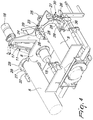
- the automatic stuffing machine for food products designated generally by the reference numeral 1, comprises a base framework 2, on which at least one forming die 3 for the product to be stuffed is mounted.
- the basic framework 2 further supports a pusher 4, which is adapted to cause the translation of the product, after its forming in the die 3, along an advancement direction 4a, so that the formed product can pass through a stuffing tube 5, on the outer surface of which at least one tubular casing 6 is fitted which is intended to wrap around the product and is constituted for example by an elastic net, by a gut casing or the like.
- the pusher 4 is capable of causing the translation of the formed product until it exits from the stuffing tube 5, making it rest, completely wrapped in the tubular casing 6, on a resting surface 7 that is defined on the base framework 2.
- the machine has at least one tube changer body 8, which supports at least two stuffing tubes 5 and can be moved, with respect to the base framework 2, in order to bring in each instance one of the stuffing tubes 5 into a working position, in which it is located at the region of action of the pusher 4, and at least one stuffing tube 5 to a resting position, in which loading of a new tubular casing 6 is allowed, for a subsequent operation for stuffing the product.
- means are provided for detachable connection between the forming die 3 and the stuffing tube 5 arranged in the working position, which are adapted to pass from an active condition, in which they provide a continuous sealed connection, with respect to the product to be stuffed for example made into sausages, between the forming die 3 and the stuffing tube 5 arranged in the working position, to an inactive condition, in which they define a space between the forming die 3 and the stuffing tube 5 arranged in the working position, in order to allow the movement of the tube changer body 8 with respect to the base framework 2, thus allowing to bring another stuffing tube 5 to the working position, and vice versa.
- means 9 for relative movement along a direction that is substantially parallel to the direction of advancement 4a of the product, at least between at least one connecting portion of the stuffing tube 5 arranged in the working position and at least one connecting element 10 which is associated or associable with the forming die 3.
- the relative movement means 9 allow to move the stuffing tube 5 arranged in the working position and the connecting element 10 from a mutually coupled condition, in which a continuous sealed connection is provided between the forming die 3 and the stuffing tube 5 arranged in the working position, to a mutual disengagement condition, with axial spacing of one with respect to the other, in order to allow the movement of the tube changer body 8 with respect to the base framework 2, so as to bring another stuffing tube 5 to the working position, and vice versa.
- At least one portion of the stuffing tube 5 that is in the working position and at least one portion of the connecting element 10 are inserted axially one inside the other, so as to ensure the best seal and avoid any possibility of product leakage.
- the tube changer body 8 is mounted so that it can rotate on the base framework 2 about a rotation axis 8a that is substantially parallel to the advancement direction 4a of the product and the stuffing tubes 5 are arranged around its rotation axis 8a.
- the rotary motion of the tube changer body 8 with respect to the base framework 2 is provided by way of turning means 11, which are activated on command until a stuffing tube 5 is arranged in the working position.
- the connecting element 10 comprises a sleeve 12, which is, or is suitable to be, connected hermetically to the forming die 3 and is arranged substantially coaxially to the direction of advancement 4a of the product.
- the sleeve 12 allows to provide in practice an interconnection between the forming die 3 and the stuffing tube 5 in the working position.
- the relative movement means 9 comprise means 13 for the axial translation of the sleeve 12 with respect to the forming die 3 along a direction that is substantially parallel to the advancement direction 4a of the product.
- the sleeve 12 is coupled hermetically to one end of the forming die 3 with the possibility to translate axially along the product advancement direction 4a, while the axial translation means 13 are constituted conveniently by a pair of movement cylinders 13a, 13b, which are adapted to produce an approach or spacing motion of the sleeve 12 with respect to the stuffing tube 5.
- the sleeve 12 can be for example fitted so that it can slide on a tubular portion 3a that is fixed coaxially to the forming die 3.
- the relative movement means 9 comprise means 14 for the axial movement of the tube changer body 8 with respect to the basic framework 2 along a direction that is substantially parallel to the product advancement direction 4a.
- the axial movement means 14 allow to produce a movement in an axial direction of the tube changer body 8 and therefore of the stuffing tubes 5 with respect to the connecting element 10, so as to produce an approach of the stuffing tube 5 that is in the working position toward the connecting element 10, until the condition of mutual coupling between the stuffing tube 5 in the working position and the connecting element 10 is provided, consequently achieving a continuous sealed connection between the forming die 3 and the stuffing tube 5 in the working position.
- the axial movement means 14 allow to move in an axial direction the tube changer body 8 also in the opposite direction, in order to cause the spacing of the stuffing tube 5 in the working position from the connecting element 10, so as to obtain mutual disengagement between the stuffing tube 5 in the working position and the connecting element 10 and thus allow the possibility to actuate again the tube changer body 8 of the stuffing tubes 5 in order to move another stuffing tube 5 to the working position.
- the sleeve 12 that provides the connecting element 10 can, in this case, be fixed to the base framework 2 or be integrally connected by the forming die 3.
- the tube changer body 8 is advantageously mounted so that it can rotate about a supporting shaft 15 that is arranged substantially parallel to the product advancement direction 4a.
- the means 11 for turning the tube changer body 8 conveniently comprise a pulley 16, which is mounted rotatably on the supporting shaft 15 and is connected integrally in rotation to the tube changer body 8.
- the pulley 16 receives motion from a transmission element 17, such as for example a belt or chain, which is functionally connected to an actuation motor 18.
- the tube changer body 8 is further mounted so that it can slide along the supporting shaft 15 and the axial movement means 14 are conveniently provided by one or more actuation cylinders 14a, 14b, which act between the tube changer body 8 and the base framework 2 in order to produce the sliding of the tube changer body 8 along the supporting shaft 15 toward or away from the pulley 16.
- the movement actuated by the actuation cylinders 14a, 14b of the tube changer body 8 along the supporting shaft 15 causes the movement of the stuffing tube 5, which is in the working position, between the condition of mutual coupling with the connecting element 10 and the condition of mutual disengagement from the connecting element 10.
- the actuation cylinders 14a, 14b are conveniently connected to the tube changer body 8 by means of a supporting ring 19, which defines, on its inner surface, a circular groove 19a that is engaged slidingly by an annular body 20, which in turn is fixed axially to the tube changer body 8 in order to allow the rotation of such tube changer body with respect to the supporting ring 19.
- means for kinematic connection to the tube changer body 8 are associated with the pulley 16 and are constituted for example by one or more connection pins 21, which are fixed to the pulley 16 and have the function of connecting the tube changer body 8 to the pulley 16 in order to keep the tube changer body 8 integral with the pulley 16 in its rotary motion, though allowing the tube changer body 8 the possibility to slide with respect to the pulley 16 along the supporting shaft 15.
- connection pins 21 are extended substantially parallel to the axis of the supporting shaft 15 and are conveniently inserted slidingly in respective guiding channels 22 defined in the tube changer body 8.
- the removable locking means 23 can be activated on command once the stuffing tube 5 that is in the working position reaches the condition of mutual coupling with the connecting element 10.
- the removable locking means 23 comprise a retention ring 24, which is arranged substantially coaxially to the product advancement direction 4a and is supported, so that it can rotate about its own axis, by a wall 25, which is fixed to the base framework 2.
- the wall 25 protrudes upwardly from the base framework 2 and is interposed between the forming die 3 and the stuffing tubes 5.
- the wall 25 supports advantageously also the supporting shaft 15 and the actuation motor 18.
- the retention ring 24 is provided internally with a plurality of engagement protrusions 26, which are mutually angularly spaced around the axis of the retention ring 24.
- a respective flange 27 is fixed to each stuffing tube 5 and is provided, along its outer perimeter, with recesses 28 that can be crossed by the engagement protrusions 26 of the retention ring 24 and are alternated with raised portions 29.
- the retention ring 24 can be actuated rotationally by actuator means 30, which act appropriately between the retention ring 24 and the wall 25.
- the retention ring 24 is capable of passing from a disengagement condition, shown in Figure 5 , in which its engagement protrusions 26 are arranged at the recesses 28, so as to allow translational motion, along a direction that is substantially parallel to the product advancement direction 4a, of the stuffing tube 5 that is arranged in the working position between the mutually coupled condition and the mutual disengagement condition with the connecting element 10, to an engagement condition, shown in Figure 4 , in which its engagement protrusions 26 are misaligned with respect to the recesses 28, so as to lock the flange 27 of the stuffing tube 5 that is in the working position between the retention ring 24 and the wall 25, once the stuffing tube 5 arranged in the working position is in the condition for mutual coupling with the connecting element 10.
- the stuffing tubes 5 are coupled detachably to the tube changer body 8 in order to allow their replacement with another stuffing tube 5 that is loaded with a new tubular casing 6 when they are in the inactive condition.
- each stuffing tube 5 there is, on the tube changer body 8, a respective receptacle 31, which is open on one side in order to allow the passage of the corresponding stuffing tube 5.
- the coupling of the stuffing tubes 5 to the tube changer body 8 at the corresponding receptacles 31 is provided conveniently by way of engagement pins 32, which are fixed to the flange 27 of the stuffing tubes 5 and are substantially parallel to such stuffing tubes.
- the engagement pins 32 can be coupled detachably in respective locking seats 33 defined on the tube changer body 8.
- the locking seats 33 there are removable locking means 34, which are adapted to engage a circular engagement hollow 35 that is provided on the engagement pins 32 in order to prevent their axial extraction from the locking seats 33.
- At least one sensor 36 which is adapted to detect the reaching of the working position by one of the stuffing tubes 5 as a consequence of the actuation in motion of the tube changer body 8 with respect to the base framework 2.
- the senor 36 is functionally connected to the means 11 for turning the tube changer body 8 and more precisely to the actuation motor 18 so that it can command the halting of the turning means 11 of the tube changer body 8 when the working position is reached by one of the stuffing tubes 5.
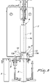
- the braking means 37 can be moved slidingly on command along a direction that is substantially parallel to the advancement direction 4a of the product, so as to be able to pass from an active condition, shown for example in Figure 2 , in which they are adapted to brake the tubular casing 6 supported by the stuffing tube 5 in the working position, at least when the latter is in the condition of mutual coupling with the connecting element 10, to an inactive condition, shown for example in Figure 3 , which is spaced axially with respect to the active condition, in a direction that is opposite to the forming die 3, in order to allow the rotation of the tube changer body 8 about its own rotation axis 8a, after the stuffing tube 5 in the working position and the connecting element 10 have been moved to the mutual disengagement condition, and vice versa.
- the braking means 37 are supported by a frame 38 and are for example constituted by a pair of jaws 39a, 39b, which are intended to act on mutually opposite sides with respect to the stuffing tube 5 in the working position.
- the frame 38 is supported so that it can slide by the supporting shaft 15 and optionally also by an additional guiding shaft 40, which is arranged opposite the supporting shaft 15.
- At least one linear actuator 41 acts between the frame 38 and the base framework 2 and allows to translate the frame 38 and therefore the braking means 37 along the supporting shaft 15 between said active condition and said inactive condition. More preferably, there are two linear actuators 41, one acting between the frame 38 and the supporting shaft 15 and the other one acting between the frame 38 and the guiding shaft 40.
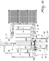
- the forming die 3 can be moved by conveyance means, constituted for example by a belt conveyor or the like, along a movement direction 42 in order to allow its replacement with other forming dies 3, already loaded with product and intended to be moved in each instance into the region of action of the pusher 4 by said conveyance means.
- conveyance means constituted for example by a belt conveyor or the like
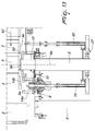
- such sealed removable connection means comprise a connecting ring 43, which can move along the axis of the connecting element 10 in order to pass from an advanced connecting condition, visible in Figure 10 , in which it straddles the connecting element 10 and a tubular portion 3a of the forming die 3 that is arranged in the region of action of the pusher 4, so as to create a sealed connection between the forming die 3 and the connecting element 10, to a retracted disengagement condition, shown in particular in Figure 11 , in which it is uncoupled from the forming die 3 and more particularly from its tubular portion 3a, in order to allow its movement on the part of the conveyance means.
- the movement of the connecting ring 43 between the advanced connecting condition and the retracted disengagement condition is conveniently actuated by means of a pair of actuation cylinders 44a and 44b, which act between the connecting ring 43 and the base framework 2.
- the movement cylinders 13a, 13b are activated so as to extract the sleeve 12 from the stuffing tube 5 in the working position, once the tubular casing 6 loaded on the stuffing tube 5 that is in the working position has been depleted.
- the means 11 for turning the tube changer body 8 are activated so as to move to the working position the stuffing tube 5 that is in the resting position and has a new tubular casing 6, ready to be used, already loaded thereon.
- the rotation of the tube changer body 8 is stopped, as a consequence of a stop signal that arrives for example from the sensor 36, and the movement cylinders 13a and 13b are activated again so as to insert the sleeve 12 in the new stuffing tube in the working position.
- the stuffing tube 5 that previously was in the working position can instead reach the resting position, where it can be loaded again with another tubular casing 6 or be removed from the tube changer body 8 and replaced with another stuffing tube 5 that is already loaded with a tubular casing 6.
- the actuator means 30 of the retention ring 24 are activated so as to move the retention ring 24 from the condition of engagement with the raised portions 29 of the flange 27 of the stuffing tube 5 in the working position to its disengagement condition, in which its engagement protrusions 26 are arranged at the recesses 28 of the flange 27, so as to release the stuffing tube 5 from locking to the wall 25.
- actuation cylinders 14a and 14b are activated so as to produce a movement of the tube changer body 8 along the supporting shaft 15, which causes the spacing, with consequent disengagement, of the stuffing tube 5 in the working position from the connecting element 10.
- linear actuators 41 are activated in order to move the braking means 37 into their inactive condition.
- the means 11 for turning the tube changer body 8 are activated until the stuffing tube 5 that is in the resting position is brought to the working position.
- the actuation motor 18 is activated so as to turn the pulley 16, which, by remaining rotationally integral with the tube changer body 8 by way of the connection pins 21, entrains with itself in rotation also the tube changer body 8.
- the rotation of the tube changer body 8 continues at least until the sensor 36 detects the presence of a stuffing tube 5 in the working position. Upon detection of a new stuffing tube 5 in the working position, the sensor 36 commands the stopping of the actuation motor 18, so as to stop the rotation of the tube changer body 8.
- actuation cylinders 14a, 14b are activated again so as to produce a translational motion of the tube changer body 8 along the supporting shaft 15 that allows to move the new stuffing tube 5 to the working position in a condition of mutual coupling with the connecting element 10.
- the actuation means 30 are activated so as to move the retention ring 24 from the disengagement condition to the engagement condition, so as to lock the new stuffing tube 5 in the working position to the wall 25 and therefore to the base framework 2.
- the linear actuators 41 are then also activated so as to return the braking means 37 to their active condition.
- the stuffing tube 5 that previously was in the working position is moved to the resting position, where it can be reloaded with a new tubular casing 6, optionally after uncoupling it from the tube changer body 8, by way of the extraction of its engagement pins 32 from the respective receptacles 31, so as to prepare it for a new work cycle or replacing it with another stuffing tube on which a tubular casing 6 has already been loaded.
- the connecting ring 43 is moved from the advanced connecting condition to the retracted disengagement condition by way of the activation of the actuation cylinders 44a and 44b. Then the means for the conveyance of the forming dies 3 are activated and position another forming die 3 in the region of action of the pusher 4, moving away the previous one.
- the actuation cylinders 44a and 44b are activated in order to move the connecting ring 43 to the advanced connecting condition, so as to make it straddle the connecting element 10 and the tubular portion 3 a of the new forming die 3 in the region of action of the pusher 4.
- the invention is capable of achieving fully the intended aim, since it allows to obtain a rapid changing of the stuffing tubes, once their reserve of tubular casing has been depleted, at the same time ensuring a valid seal between the forming die and the stuffing tubes, so as to prevent losses of product.
- the expandable gasket 50 is adapted to pass from an extended condition, shown in Figure 12 , in which it provides, between the stuffing tube 5 in the working position and the forming die 3, a sealed connection with respect to the product entrained by the pusher 4, to a retracted condition, shown in Figure 13 , in which a space is provided between the stuffing tube 5 in the working position and the forming die 3, so as to allow the movement of the tube changer body 8 or of the forming die 3, and vice versa.
- the expandable gasket 50 provides an alternative embodiment of the sealed removable connection means cited above.
- the expandable gasket 50 has a substantially annular shape and is advantageously associated, at a first axial end thereof, with the connecting element 10 that is intended to be connected to the stuffing tube 5 in the working position. More particularly, the expandable gasket 50 is fixed, at its said first axial end, to the sleeve 12.
- the expandable gasket 50 is inflatable by way of means for injecting pressurized air, not shown, which are connected to an air chamber defined inside such expandable gasket in order to allow its transition from the retracted condition to the expanded condition.
- the expandable gasket 50 in passing from the retracted condition, in which it is deflated, to the extended condition, in which it is inflated with air, the expandable gasket 50 becomes elongated, with the consequence that its second axial end is translated, substantially parallel to the advancement direction 4a of the product to be stuffed, toward a tubular portion 3a that is connected to the forming die 3 that is in the region of action of the pusher 4, so as to engage its lateral surface and thus provide a sealed connection between the forming die 3 and the stuffing tube 5 in the working position, as shown in Figure 12 .
- an expandable gasket 50 it is possible to provide optionally also the removable connection between a fixed forming die 3 and the stuffing tube 5 in the working position.
- the expandable gasket 50 is fixed at a first axial end to the forming die 3, while its second axial end can translate, as a consequence of its transition from the retracted condition to the extended condition, toward the stuffing tube 5 that is arranged in the working position, until it engages it hermetically.
- the materials used may be any according to requirements.
Landscapes
- Engineering & Computer Science (AREA)
- Life Sciences & Earth Sciences (AREA)
- Wood Science & Technology (AREA)
- Zoology (AREA)
- Food Science & Technology (AREA)
- Mechanical Engineering (AREA)
- Containers And Plastic Fillers For Packaging (AREA)
Applications Claiming Priority (1)
| Application Number | Priority Date | Filing Date | Title |
|---|---|---|---|
| ITVR20150052 | 2015-04-01 |
Publications (2)
| Publication Number | Publication Date |
|---|---|
| EP3075251A1 true EP3075251A1 (de) | 2016-10-05 |
| EP3075251B1 EP3075251B1 (de) | 2018-06-06 |
Family
ID=53539875
Family Applications (2)
| Application Number | Title | Priority Date | Filing Date |
|---|---|---|---|
| EP16163300.3A Active EP3075251B1 (de) | 2015-04-01 | 2016-03-31 | Automatische füllmaschine für lebensmittelprodukte |
| EP16163323.5A Withdrawn EP3075252A1 (de) | 2015-04-01 | 2016-03-31 | Automatische füllmaschine für lebensmittelprodukte |
Family Applications After (1)
| Application Number | Title | Priority Date | Filing Date |
|---|---|---|---|
| EP16163323.5A Withdrawn EP3075252A1 (de) | 2015-04-01 | 2016-03-31 | Automatische füllmaschine für lebensmittelprodukte |
Country Status (3)
| Country | Link |
|---|---|
| US (1) | US9622491B2 (de) |
| EP (2) | EP3075251B1 (de) |
| ES (1) | ES2686310T3 (de) |
Cited By (2)
| Publication number | Priority date | Publication date | Assignee | Title |
|---|---|---|---|---|
| CN106516230A (zh) * | 2016-12-22 | 2017-03-22 | 严福英 | 一种厨房自动装餐装置 |
| EP3449729A1 (de) * | 2017-08-31 | 2019-03-06 | VEMAG Maschinenbau GmbH | Vorrichtung zum bestücken eines füllrohrs und betreffendes bestückungsverfahren |
Families Citing this family (1)
| Publication number | Priority date | Publication date | Assignee | Title |
|---|---|---|---|---|
| US11807409B1 (en) | 2022-04-22 | 2023-11-07 | Tipper Tie, Inc. | Netting machine with multiple netting chute exchange system |
Citations (4)
| Publication number | Priority date | Publication date | Assignee | Title |
|---|---|---|---|---|
| FR2160734A1 (en) * | 1971-11-24 | 1973-07-06 | Gen Viandes Salaiso | Introduction of meat into elastic net covering - using two moulds alternately |
| FR2614602A1 (fr) | 1987-04-28 | 1988-11-04 | Freres & Cie Charles | Machine permettant la mise sous filet automatique de pieces de salaisons, du type saucissons, jambons et produits similaires apres embossage |
| US6572464B1 (en) * | 2002-05-31 | 2003-06-03 | Townsend Engineering Company | Method and means for rapid loading of casing-bearing sleeves on a sausage making machine |
| US20080311835A1 (en) * | 2007-06-04 | 2008-12-18 | Hitec Co., Ltd. | Apparatus and method for setting a casing to a nozzle feeding food-material of sausage or the like into the casing |
Family Cites Families (6)
| Publication number | Priority date | Publication date | Assignee | Title |
|---|---|---|---|---|
| US4955109A (en) * | 1989-09-20 | 1990-09-11 | Delaware Capital Formation, Inc. | Pivoting horn |
| ITMN20000007A1 (it) * | 2000-01-31 | 2001-07-31 | Inox Meccanica Srl | Dispositivo in macchina porzionatrice-insaccatrice di carne per il collegamento con macchina clippatrice |
| US7441386B2 (en) * | 2006-10-27 | 2008-10-28 | Poly-Clip System Corp. | Apparatus for forming tubes in nets |
| EP2769622B1 (de) * | 2013-02-20 | 2017-09-13 | Poly-clip System GmbH & Co. KG | Polygonal geformter Füllstutzen mit entsprechender Gehäusebremse |
| DE202013010285U1 (de) * | 2013-11-13 | 2015-03-06 | Vemag Maschinenbau Gmbh | Vorrichtung zum Füllen schlauchförmiger Hüllen |
| ITVR20130281A1 (it) * | 2013-12-13 | 2015-06-14 | Inox Meccanica Srl | Procedimento di insacco di prodotti alimentari e macchina insaccatrice per la sua esecuzione |
-
2016
- 2016-03-30 US US15/085,983 patent/US9622491B2/en active Active
- 2016-03-31 ES ES16163300.3T patent/ES2686310T3/es active Active
- 2016-03-31 EP EP16163300.3A patent/EP3075251B1/de active Active
- 2016-03-31 EP EP16163323.5A patent/EP3075252A1/de not_active Withdrawn
Patent Citations (4)
| Publication number | Priority date | Publication date | Assignee | Title |
|---|---|---|---|---|
| FR2160734A1 (en) * | 1971-11-24 | 1973-07-06 | Gen Viandes Salaiso | Introduction of meat into elastic net covering - using two moulds alternately |
| FR2614602A1 (fr) | 1987-04-28 | 1988-11-04 | Freres & Cie Charles | Machine permettant la mise sous filet automatique de pieces de salaisons, du type saucissons, jambons et produits similaires apres embossage |
| US6572464B1 (en) * | 2002-05-31 | 2003-06-03 | Townsend Engineering Company | Method and means for rapid loading of casing-bearing sleeves on a sausage making machine |
| US20080311835A1 (en) * | 2007-06-04 | 2008-12-18 | Hitec Co., Ltd. | Apparatus and method for setting a casing to a nozzle feeding food-material of sausage or the like into the casing |
Cited By (4)
| Publication number | Priority date | Publication date | Assignee | Title |
|---|---|---|---|---|
| CN106516230A (zh) * | 2016-12-22 | 2017-03-22 | 严福英 | 一种厨房自动装餐装置 |
| CN106516230B (zh) * | 2016-12-22 | 2019-01-01 | 严福英 | 一种厨房自动装餐装置 |
| EP3449729A1 (de) * | 2017-08-31 | 2019-03-06 | VEMAG Maschinenbau GmbH | Vorrichtung zum bestücken eines füllrohrs und betreffendes bestückungsverfahren |
| US10306900B2 (en) | 2017-08-31 | 2019-06-04 | Vemag Maschinenbau Gmbh | Apparatus for equipping a filling tube and related equipping method |
Also Published As
| Publication number | Publication date |
|---|---|
| US9622491B2 (en) | 2017-04-18 |
| EP3075251B1 (de) | 2018-06-06 |
| ES2686310T3 (es) | 2018-10-17 |
| EP3075252A1 (de) | 2016-10-05 |
| US20160286828A1 (en) | 2016-10-06 |
Similar Documents
| Publication | Publication Date | Title |
|---|---|---|
| EP3075251B1 (de) | Automatische füllmaschine für lebensmittelprodukte | |
| FI68344B (fi) | Foerfarande och anordning foer reglering av diametern och aendarna av en i ett hoelje sluten produkt | |
| US8376002B2 (en) | Apparatus for filling tube-shaped or bag-shaped packaging | |
| JPS5852882B2 (ja) | 流動性の材料をひだ付ケ−シング内に填充するための填充装置および方法 | |
| ITVR20010124A1 (it) | Testa di stallonatura con unghia per il montaggio/smontaggio di un pneumatico per macchina smontagomme. | |
| US3438832A (en) | Tire building machine | |
| ITMI20130050A1 (it) | Procedimento per attuare la chiusura automatizzata di un'estremita' assiale di un manufatto tubolare e il suo scarico in assetto a rovescio ed apparecchiatura per la sua esecuzione. | |
| US4577370A (en) | Method and apparatus for opening axially shirring and dividing off thin-walled, cord-shaped tubular casing material, especially casings made of synthetic material, for the sausage manufacture | |
| JPH0113330B2 (de) | ||
| JPS609766B2 (ja) | 骨なしハムの填充方法及び装置 | |
| EP2769622B1 (de) | Polygonal geformter Füllstutzen mit entsprechender Gehäusebremse | |
| JPS5864906A (ja) | 弾性的に拡張可能なチユ−ブ状包装材内に細長く伸直した円筒状物品を包装する方法と装置 | |
| EP0268206B1 (de) | Maschine zum Formen, Füllen und Abbinden von Nahrungsprodukten | |
| US4583264A (en) | Stuffing apparatus having casting article engaging and rotating means | |
| EP3075254B1 (de) | Füllmaschine für lebensmittel | |
| EP2692235B1 (de) | Clipmodul-Antriebsvorrichtung und Verfahren zum Bewegen eines Clipmoduls | |
| EP2883696B1 (de) | Vorrichtung und Verfahren zum Befüllen einer Verpackungshülle | |
| EP3075253B1 (de) | Maschine und verfahren zum füllen von lebensmittelprodukten | |
| ITMI20102172A1 (it) | Apparato per il montaggio e lo smontaggio di uno pneumatico dal/sul relativo cerchio | |
| ITMO20080311A1 (it) | Stampo per la pressatura di prodotti alimentari | |
| ITPT20110009U1 (it) | Dispositivo per la giunzione lineare e l'accumulo di budella per insaccati | |
| UA120709C2 (uk) | Кліпсатор | |
| ITMI20121604A1 (it) | Apparecchiatura e procedimento per la produzione di collant | |
| ITVR990022A1 (it) | Dispositivo automatico per il taglio a spicchi di cuori di carciofocotti. | |
| JP2024040857A (ja) | 複合食品の製造方法及び複合食品の製造装置 |
Legal Events
| Date | Code | Title | Description |
|---|---|---|---|
| PUAI | Public reference made under article 153(3) epc to a published international application that has entered the european phase |
Free format text: ORIGINAL CODE: 0009012 |
|
| AK | Designated contracting states |
Kind code of ref document: A1 Designated state(s): AL AT BE BG CH CY CZ DE DK EE ES FI FR GB GR HR HU IE IS IT LI LT LU LV MC MK MT NL NO PL PT RO RS SE SI SK SM TR |
|
| AX | Request for extension of the european patent |
Extension state: BA ME |
|
| STAA | Information on the status of an ep patent application or granted ep patent |
Free format text: STATUS: REQUEST FOR EXAMINATION WAS MADE |
|
| 17P | Request for examination filed |
Effective date: 20170307 |
|
| RBV | Designated contracting states (corrected) |
Designated state(s): AL AT BE BG CH CY CZ DE DK EE ES FI FR GB GR HR HU IE IS IT LI LT LU LV MC MK MT NL NO PL PT RO RS SE SI SK SM TR |
|
| REG | Reference to a national code |
Ref country code: DE Ref legal event code: R079 Ref document number: 602016003269 Country of ref document: DE Free format text: PREVIOUS MAIN CLASS: A22C0011000000 Ipc: B65B0025000000 |
|
| GRAP | Despatch of communication of intention to grant a patent |
Free format text: ORIGINAL CODE: EPIDOSNIGR1 |
|
| STAA | Information on the status of an ep patent application or granted ep patent |
Free format text: STATUS: GRANT OF PATENT IS INTENDED |
|
| RIC1 | Information provided on ipc code assigned before grant |
Ipc: A22C 11/02 20060101ALI20171201BHEP Ipc: A22C 11/00 20060101ALI20171201BHEP Ipc: B65B 3/12 20060101ALI20171201BHEP Ipc: B65B 25/00 20060101AFI20171201BHEP Ipc: B65B 9/15 20060101ALI20171201BHEP |
|
| INTG | Intention to grant announced |
Effective date: 20171218 |
|
| GRAS | Grant fee paid |
Free format text: ORIGINAL CODE: EPIDOSNIGR3 |
|
| GRAA | (expected) grant |
Free format text: ORIGINAL CODE: 0009210 |
|
| STAA | Information on the status of an ep patent application or granted ep patent |
Free format text: STATUS: THE PATENT HAS BEEN GRANTED |
|
| AK | Designated contracting states |
Kind code of ref document: B1 Designated state(s): AL AT BE BG CH CY CZ DE DK EE ES FI FR GB GR HR HU IE IS IT LI LT LU LV MC MK MT NL NO PL PT RO RS SE SI SK SM TR |
|
| REG | Reference to a national code |
Ref country code: GB Ref legal event code: FG4D |
|
| REG | Reference to a national code |
Ref country code: CH Ref legal event code: EP Ref country code: AT Ref legal event code: REF Ref document number: 1005816 Country of ref document: AT Kind code of ref document: T Effective date: 20180615 |
|
| REG | Reference to a national code |
Ref country code: IE Ref legal event code: FG4D |
|
| REG | Reference to a national code |
Ref country code: DE Ref legal event code: R096 Ref document number: 602016003269 Country of ref document: DE |
|
| REG | Reference to a national code |
Ref country code: NL Ref legal event code: MP Effective date: 20180606 |
|
| REG | Reference to a national code |
Ref country code: ES Ref legal event code: FG2A Ref document number: 2686310 Country of ref document: ES Kind code of ref document: T3 Effective date: 20181017 |
|
| REG | Reference to a national code |
Ref country code: LT Ref legal event code: MG4D |
|
| PG25 | Lapsed in a contracting state [announced via postgrant information from national office to epo] |
Ref country code: LT Free format text: LAPSE BECAUSE OF FAILURE TO SUBMIT A TRANSLATION OF THE DESCRIPTION OR TO PAY THE FEE WITHIN THE PRESCRIBED TIME-LIMIT Effective date: 20180606 Ref country code: SE Free format text: LAPSE BECAUSE OF FAILURE TO SUBMIT A TRANSLATION OF THE DESCRIPTION OR TO PAY THE FEE WITHIN THE PRESCRIBED TIME-LIMIT Effective date: 20180606 Ref country code: CY Free format text: LAPSE BECAUSE OF FAILURE TO SUBMIT A TRANSLATION OF THE DESCRIPTION OR TO PAY THE FEE WITHIN THE PRESCRIBED TIME-LIMIT Effective date: 20180606 Ref country code: FI Free format text: LAPSE BECAUSE OF FAILURE TO SUBMIT A TRANSLATION OF THE DESCRIPTION OR TO PAY THE FEE WITHIN THE PRESCRIBED TIME-LIMIT Effective date: 20180606 Ref country code: NO Free format text: LAPSE BECAUSE OF FAILURE TO SUBMIT A TRANSLATION OF THE DESCRIPTION OR TO PAY THE FEE WITHIN THE PRESCRIBED TIME-LIMIT Effective date: 20180906 Ref country code: BG Free format text: LAPSE BECAUSE OF FAILURE TO SUBMIT A TRANSLATION OF THE DESCRIPTION OR TO PAY THE FEE WITHIN THE PRESCRIBED TIME-LIMIT Effective date: 20180906 |
|
| PG25 | Lapsed in a contracting state [announced via postgrant information from national office to epo] |
Ref country code: HR Free format text: LAPSE BECAUSE OF FAILURE TO SUBMIT A TRANSLATION OF THE DESCRIPTION OR TO PAY THE FEE WITHIN THE PRESCRIBED TIME-LIMIT Effective date: 20180606 Ref country code: GR Free format text: LAPSE BECAUSE OF FAILURE TO SUBMIT A TRANSLATION OF THE DESCRIPTION OR TO PAY THE FEE WITHIN THE PRESCRIBED TIME-LIMIT Effective date: 20180907 Ref country code: LV Free format text: LAPSE BECAUSE OF FAILURE TO SUBMIT A TRANSLATION OF THE DESCRIPTION OR TO PAY THE FEE WITHIN THE PRESCRIBED TIME-LIMIT Effective date: 20180606 Ref country code: RS Free format text: LAPSE BECAUSE OF FAILURE TO SUBMIT A TRANSLATION OF THE DESCRIPTION OR TO PAY THE FEE WITHIN THE PRESCRIBED TIME-LIMIT Effective date: 20180606 |
|
| REG | Reference to a national code |
Ref country code: AT Ref legal event code: MK05 Ref document number: 1005816 Country of ref document: AT Kind code of ref document: T Effective date: 20180606 |
|
| PG25 | Lapsed in a contracting state [announced via postgrant information from national office to epo] |
Ref country code: NL Free format text: LAPSE BECAUSE OF FAILURE TO SUBMIT A TRANSLATION OF THE DESCRIPTION OR TO PAY THE FEE WITHIN THE PRESCRIBED TIME-LIMIT Effective date: 20180606 |
|
| PG25 | Lapsed in a contracting state [announced via postgrant information from national office to epo] |
Ref country code: SK Free format text: LAPSE BECAUSE OF FAILURE TO SUBMIT A TRANSLATION OF THE DESCRIPTION OR TO PAY THE FEE WITHIN THE PRESCRIBED TIME-LIMIT Effective date: 20180606 Ref country code: PL Free format text: LAPSE BECAUSE OF FAILURE TO SUBMIT A TRANSLATION OF THE DESCRIPTION OR TO PAY THE FEE WITHIN THE PRESCRIBED TIME-LIMIT Effective date: 20180606 Ref country code: AT Free format text: LAPSE BECAUSE OF FAILURE TO SUBMIT A TRANSLATION OF THE DESCRIPTION OR TO PAY THE FEE WITHIN THE PRESCRIBED TIME-LIMIT Effective date: 20180606 Ref country code: IS Free format text: LAPSE BECAUSE OF FAILURE TO SUBMIT A TRANSLATION OF THE DESCRIPTION OR TO PAY THE FEE WITHIN THE PRESCRIBED TIME-LIMIT Effective date: 20181006 Ref country code: CZ Free format text: LAPSE BECAUSE OF FAILURE TO SUBMIT A TRANSLATION OF THE DESCRIPTION OR TO PAY THE FEE WITHIN THE PRESCRIBED TIME-LIMIT Effective date: 20180606 Ref country code: EE Free format text: LAPSE BECAUSE OF FAILURE TO SUBMIT A TRANSLATION OF THE DESCRIPTION OR TO PAY THE FEE WITHIN THE PRESCRIBED TIME-LIMIT Effective date: 20180606 Ref country code: RO Free format text: LAPSE BECAUSE OF FAILURE TO SUBMIT A TRANSLATION OF THE DESCRIPTION OR TO PAY THE FEE WITHIN THE PRESCRIBED TIME-LIMIT Effective date: 20180606 |
|
| PG25 | Lapsed in a contracting state [announced via postgrant information from national office to epo] |
Ref country code: SM Free format text: LAPSE BECAUSE OF FAILURE TO SUBMIT A TRANSLATION OF THE DESCRIPTION OR TO PAY THE FEE WITHIN THE PRESCRIBED TIME-LIMIT Effective date: 20180606 |
|
| REG | Reference to a national code |
Ref country code: DE Ref legal event code: R097 Ref document number: 602016003269 Country of ref document: DE |
|
| PLBE | No opposition filed within time limit |
Free format text: ORIGINAL CODE: 0009261 |
|
| STAA | Information on the status of an ep patent application or granted ep patent |
Free format text: STATUS: NO OPPOSITION FILED WITHIN TIME LIMIT |
|
| 26N | No opposition filed |
Effective date: 20190307 |
|
| PG25 | Lapsed in a contracting state [announced via postgrant information from national office to epo] |
Ref country code: DK Free format text: LAPSE BECAUSE OF FAILURE TO SUBMIT A TRANSLATION OF THE DESCRIPTION OR TO PAY THE FEE WITHIN THE PRESCRIBED TIME-LIMIT Effective date: 20180606 Ref country code: SI Free format text: LAPSE BECAUSE OF FAILURE TO SUBMIT A TRANSLATION OF THE DESCRIPTION OR TO PAY THE FEE WITHIN THE PRESCRIBED TIME-LIMIT Effective date: 20180606 |
|
| PG25 | Lapsed in a contracting state [announced via postgrant information from national office to epo] |
Ref country code: MC Free format text: LAPSE BECAUSE OF FAILURE TO SUBMIT A TRANSLATION OF THE DESCRIPTION OR TO PAY THE FEE WITHIN THE PRESCRIBED TIME-LIMIT Effective date: 20180606 |
|
| REG | Reference to a national code |
Ref country code: CH Ref legal event code: PL |
|
| PG25 | Lapsed in a contracting state [announced via postgrant information from national office to epo] |
Ref country code: AL Free format text: LAPSE BECAUSE OF FAILURE TO SUBMIT A TRANSLATION OF THE DESCRIPTION OR TO PAY THE FEE WITHIN THE PRESCRIBED TIME-LIMIT Effective date: 20180606 Ref country code: LU Free format text: LAPSE BECAUSE OF NON-PAYMENT OF DUE FEES Effective date: 20190331 |
|
| REG | Reference to a national code |
Ref country code: BE Ref legal event code: MM Effective date: 20190331 |
|
| PG25 | Lapsed in a contracting state [announced via postgrant information from national office to epo] |
Ref country code: LI Free format text: LAPSE BECAUSE OF NON-PAYMENT OF DUE FEES Effective date: 20190331 Ref country code: CH Free format text: LAPSE BECAUSE OF NON-PAYMENT OF DUE FEES Effective date: 20190331 Ref country code: IE Free format text: LAPSE BECAUSE OF NON-PAYMENT OF DUE FEES Effective date: 20190331 |
|
| PG25 | Lapsed in a contracting state [announced via postgrant information from national office to epo] |
Ref country code: BE Free format text: LAPSE BECAUSE OF NON-PAYMENT OF DUE FEES Effective date: 20190331 |
|
| PG25 | Lapsed in a contracting state [announced via postgrant information from national office to epo] |
Ref country code: TR Free format text: LAPSE BECAUSE OF FAILURE TO SUBMIT A TRANSLATION OF THE DESCRIPTION OR TO PAY THE FEE WITHIN THE PRESCRIBED TIME-LIMIT Effective date: 20180606 |
|
| PG25 | Lapsed in a contracting state [announced via postgrant information from national office to epo] |
Ref country code: PT Free format text: LAPSE BECAUSE OF FAILURE TO SUBMIT A TRANSLATION OF THE DESCRIPTION OR TO PAY THE FEE WITHIN THE PRESCRIBED TIME-LIMIT Effective date: 20181008 Ref country code: MT Free format text: LAPSE BECAUSE OF NON-PAYMENT OF DUE FEES Effective date: 20190331 |
|
| GBPC | Gb: european patent ceased through non-payment of renewal fee |
Effective date: 20200331 |
|
| PG25 | Lapsed in a contracting state [announced via postgrant information from national office to epo] |
Ref country code: GB Free format text: LAPSE BECAUSE OF NON-PAYMENT OF DUE FEES Effective date: 20200331 |
|
| PG25 | Lapsed in a contracting state [announced via postgrant information from national office to epo] |
Ref country code: HU Free format text: LAPSE BECAUSE OF FAILURE TO SUBMIT A TRANSLATION OF THE DESCRIPTION OR TO PAY THE FEE WITHIN THE PRESCRIBED TIME-LIMIT; INVALID AB INITIO Effective date: 20160331 |
|
| PG25 | Lapsed in a contracting state [announced via postgrant information from national office to epo] |
Ref country code: MK Free format text: LAPSE BECAUSE OF FAILURE TO SUBMIT A TRANSLATION OF THE DESCRIPTION OR TO PAY THE FEE WITHIN THE PRESCRIBED TIME-LIMIT Effective date: 20180606 |
|
| REG | Reference to a national code |
Ref country code: DE Ref legal event code: R082 Ref document number: 602016003269 Country of ref document: DE Representative=s name: SCHIEBER - FARAGO PATENTANWAELTE, DE Ref country code: DE Ref legal event code: R082 Ref document number: 602016003269 Country of ref document: DE Representative=s name: FARAGO PATENTANWALTSGESELLSCHAFT MBH, DE |
|
| REG | Reference to a national code |
Ref country code: DE Ref legal event code: R082 Ref document number: 602016003269 Country of ref document: DE Representative=s name: SCHIEBER - FARAGO PATENTANWAELTE, DE |
|
| P01 | Opt-out of the competence of the unified patent court (upc) registered |
Effective date: 20230529 |
|
| PGFP | Annual fee paid to national office [announced via postgrant information from national office to epo] |
Ref country code: ES Payment date: 20250404 Year of fee payment: 10 |
|
| PGFP | Annual fee paid to national office [announced via postgrant information from national office to epo] |
Ref country code: DE Payment date: 20260313 Year of fee payment: 11 |
|
| PGFP | Annual fee paid to national office [announced via postgrant information from national office to epo] |
Ref country code: IT Payment date: 20260220 Year of fee payment: 11 |
|
| PGFP | Annual fee paid to national office [announced via postgrant information from national office to epo] |
Ref country code: FR Payment date: 20260311 Year of fee payment: 11 |