EP3075285B1 - Regaleinheit mit beleuchteten regalen - Google Patents
Regaleinheit mit beleuchteten regalen Download PDFInfo
- Publication number
- EP3075285B1 EP3075285B1 EP16159602.8A EP16159602A EP3075285B1 EP 3075285 B1 EP3075285 B1 EP 3075285B1 EP 16159602 A EP16159602 A EP 16159602A EP 3075285 B1 EP3075285 B1 EP 3075285B1
- Authority
- EP
- European Patent Office
- Prior art keywords
- shelving unit
- electrical conductors
- shelves
- conductive strips
- lighting
- Prior art date
- Legal status (The legal status is an assumption and is not a legal conclusion. Google has not performed a legal analysis and makes no representation as to the accuracy of the status listed.)
- Active
Links
- 239000004020 conductor Substances 0.000 claims description 53
- 239000002184 metal Substances 0.000 claims description 5
- 238000013037 co-molding Methods 0.000 claims description 4
- 239000012777 electrically insulating material Substances 0.000 claims description 4
- 238000005286 illumination Methods 0.000 claims description 3
- 238000001746 injection moulding Methods 0.000 claims description 2
- 239000011810 insulating material Substances 0.000 description 4
- 239000000243 solution Substances 0.000 description 4
- 239000000463 material Substances 0.000 description 3
- 238000002347 injection Methods 0.000 description 2
- 239000007924 injection Substances 0.000 description 2
- 239000000758 substrate Substances 0.000 description 2
- 238000004026 adhesive bonding Methods 0.000 description 1
- 230000007613 environmental effect Effects 0.000 description 1
- 239000007769 metal material Substances 0.000 description 1
- 239000004033 plastic Substances 0.000 description 1
- 239000002985 plastic film Substances 0.000 description 1
- 238000009420 retrofitting Methods 0.000 description 1
Images





Classifications
-
- A—HUMAN NECESSITIES
- A47—FURNITURE; DOMESTIC ARTICLES OR APPLIANCES; COFFEE MILLS; SPICE MILLS; SUCTION CLEANERS IN GENERAL
- A47F—SPECIAL FURNITURE, FITTINGS, OR ACCESSORIES FOR SHOPS, STOREHOUSES, BARS, RESTAURANTS OR THE LIKE; PAYING COUNTERS
- A47F11/00—Arrangements in shop windows, shop floors or show cases
- A47F11/06—Means for bringing about special optical effects
- A47F11/10—Arrangements of light sources
-
- A—HUMAN NECESSITIES
- A47—FURNITURE; DOMESTIC ARTICLES OR APPLIANCES; COFFEE MILLS; SPICE MILLS; SUCTION CLEANERS IN GENERAL
- A47F—SPECIAL FURNITURE, FITTINGS, OR ACCESSORIES FOR SHOPS, STOREHOUSES, BARS, RESTAURANTS OR THE LIKE; PAYING COUNTERS
- A47F5/00—Show stands, hangers, or shelves characterised by their constructional features
- A47F5/10—Adjustable or foldable or dismountable display stands
- A47F5/101—Display racks with slotted uprights
- A47F5/103—Display shelving racks with the uprights aligned in only one plane
-
- A—HUMAN NECESSITIES
- A47—FURNITURE; DOMESTIC ARTICLES OR APPLIANCES; COFFEE MILLS; SPICE MILLS; SUCTION CLEANERS IN GENERAL
- A47B—TABLES; DESKS; OFFICE FURNITURE; CABINETS; DRAWERS; GENERAL DETAILS OF FURNITURE
- A47B2220/00—General furniture construction, e.g. fittings
- A47B2220/0075—Lighting
- A47B2220/0077—Lighting for furniture, e.g. cupboards and racks
-
- F—MECHANICAL ENGINEERING; LIGHTING; HEATING; WEAPONS; BLASTING
- F21—LIGHTING
- F21W—INDEXING SCHEME ASSOCIATED WITH SUBCLASSES F21K, F21L, F21S and F21V, RELATING TO USES OR APPLICATIONS OF LIGHTING DEVICES OR SYSTEMS
- F21W2131/00—Use or application of lighting devices or systems not provided for in codes F21W2102/00-F21W2121/00
- F21W2131/30—Lighting for domestic or personal use
- F21W2131/301—Lighting for domestic or personal use for furniture
Definitions
- the present invention generally relates to shelving systems for displaying products and in particular to a shelving unit with lighted shelves.
- modular systems which comprise supporting members in the form of uprights and/or panels and one or more shelves that can be mounted on these supporting members by way of suitable connecting means, for example hook-shaped elements formed or arranged at the ends of the shelves.
- Shelving units are also known, which are provided with a lighting set for lighting the shelves.
- the supporting member intended to receive the shelves is provided with a pair of conductive strips supplied by the mains through a low voltage transformer.
- On each shelf one or more lamps are mounted, whose electrical terminals are arranged such that, when a shelf is mounted onto the supporting member, they are respectively connected to the conductive strips thus forming a closed circuit that may be supplied from the mains.
- the electrical terminals of the lamps can be connected to the conductive strips indirectly by way of wires provided with suitable contact elements, or directly, e.g. when the conductive strips are housed in the uprights and these are arranged at the side edges of the shelves, whereby the lamps can be mechanically anchored to the uprights and electrically connected to the conductive strips housed therein.
- a shelving unit with lighted shelves is e.g. described in the patent publication GB 2272279 A .
- the conductive strips are arranged in special guides that may be restrained, for example by gluing, to a panel element arranged between a pair of uprights configured to allow mounting of the shelves of the shelving unit. This allows to electrify and illuminate not only new shelving units, but also existing ones.
- the guides housing the conductive strips are arranged parallel to the uprights of the shelving unit and extend vertically, parallel and aside the uprights, while the lamps are mounted on a lower surface of the shelves, opposite to the surface intended to support articles and/or products to be displayed, and they are arranged in the direction of the width of the shelving unit.
- the lamps are provided with a pair of electric wires comprising respective contact terminals of a retractable type.
- the electric wires are fixed along supporting arms of the respective shelves, so that, when mounting a shelf onto the uprights of the shelving unit, an electrical connection between the contact terminals of the lamp wires and the conductive strips is achieved at the same time.
- An idea of solution underlying the invention is to make a shelving unit with illuminable shelves of the type described in the patent publication GB 2272279 A mentioned above, but wherein the lighting set of each shelf to be illuminated comprises a single pair of rigid electrical conductors, for example in the form of bars made of a conductive material, that may be removably restrained to the shelf itself, as well as one or more lamps that are mechanically hung and electrically connected in parallel and in a removable manner to the rigid electric conductors.
- the main advantage offered by the invention is to provide a modular solution for the illumination of shelving units that may be applied both to new shelving units and to existing ones without resorting to electric wires layouts as in conventional shelving units.
- the conductive strips are associated with respective guides configured to be mounted onto the panel element of a shelving unit, and both the strips and the guides are made up of modular sectors.
- both the strips and the guides are made up of modular sectors.
- the conductive strips are formed by co-molding or co-injection of electrically conductive materials on flexible substrates, such as e.g. sheets of plastic material, and their assembly is carried out by sliding the conductive strips on a plurality of supporting members that may be mounted at discrete positions of the panel element of a shelving unit. Also in this case assembly of the lighting set involves maneuvering of components that may be easily handled.
- the supports of the conductive strips may be made up of modular sectors that may be assembled with each other, or by single bodies made of flexible materials, in order to facilitate their fitting into the uprights.
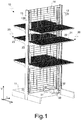
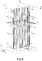
- a shelving unit according to the present invention is generally indicated by the reference number 10.
- the shelving unit 10 comprises a base 11, a pair of uprights 12, 13 that extend from the base 11 perpendicularly in a substantially vertical direction V and a panel element 14, for example made up of a web of metal wire.
- the base 11 of the shelving unit 10 stretches out in a longitudinal direction L and transverse direction T that are both parallel to a supporting surface of the shelving unit 10, for example a floor, and perpendicular to the vertical direction V.
- the panel element 14 is mainly extended in the longitudinal direction L and vertical direction V and has a relatively small thickness in the transverse direction T.
- a plurality of apertures 120, 130 are formed, e.g. substantially slotted-shaped openings, which allow mounting of a plurality of shelves 20.
- the shelves 20 extend perpendicularly to the panel element 14 in the transverse direction T.
- the apertures 120, 130 are formed on the two opposite faces of the uprights 12, 13 in the transverse direction T, thus allowing mounting of the shelves 20 on the two opposite faces of the shelving unit 10.
- Each shelf 20 comprises in a known way a supporting surface 21 for objects and/or products to be displayed, and a pair of arms 22, 23 which hold the supporting surface 21.
- the ends of the arms 22, 23 intended to be anchored to the uprights 12, 13 are hook-shaped so as to engage the apertures 120, 130 formed therein.
- the arms 22, 23 of the shelves 20 protrude from the uprights 12, 13 in the transverse direction T.
- the base 11 may be advantageously provided with a plurality of supporting feet (not shown) configured so as to allow fine adjustments of the position of the panel element 14 relative to the supporting surface of the shelving unit 10.
- the shelving unit 10 also comprises a lighting set for the illumination of the shelves.
- the lighting set comprises in a known manner a pair of conductive strips connected to the positive terminal and the negative terminal of a low-voltage transformer, respectively, for example a 24V transformer, that may be supplied from the mains.
- the transformer of the lighting set is indicated by reference number 30 and may be seen in the partially broken view of the base 11.
- the transformer 30 is e.g. housed inside the base 11 of the shelving unit 10 and e.g. fixed in correspondence of the upright 12.
- the transformer 30 may be connected to the mains through a power cable 31.
- the conductive strips connected to the positive and negative terminals of the transformer 30 are respectively indicated with reference numbers 32, 33 and stretch out in the vertical direction V e.g. aside each upright 12, 13 of the shelving unit 10.
- the lighting set further comprises at least one lamp, e.g. two lamps 40, 41 in the illustrated embodiment, as well as a single pair of electrical conductors 42, 43 for each shelf 20 to be illuminated, for example restrained to the supporting surface 21 or along the arms 22, 23.
- the lamp correspondingly has the electrical terminals arranged at its ends and configured for the connection to said electrical conductors 42, 43, e.g. traditional screw terminals.
- the electrical conductors 42, 43 are rigid elements e.g. in the form of bars or rods, so that in an assembled configuration of the shelving unit 10 the lamps 40, 41 are mechanically hung and electrically connected to the electrical conductors 42, 43.
- the wording "rigid elements” indicates elements that have a much higher flexural rigidity than traditional electric wires, and that, therefore, can act as means for mechanical supporting the lamps.
- the electrical conductors 42, 43 are removably restrained to the shelves, thus making it possible to assemble them onto either new shelving units or to existing ones upon mounting of the conductive strips 32, 33.
- the rigid electrical conductors 42, 43 extend from the respective conductive strips 32, 33 perpendicularly to the panel element 14 in the transverse direction T, and are arranged close to the arms 22, 23 of the shelves, so that the lamps 40, 41 are arranged in the longitudinal direction L. This configuration offers the advantage of allowing to illuminate the whole supporting surface of the shelves.
- the lamps are preferably arranged below the supporting surfaces 21 of the shelves in the vertical direction V, so as not to interfere with the products that will be placed thereon.
- the lighting set is associated only to the intermediate shelves of the shelving unit 10 and two lamps 40, 41 are mounted in parallel on each shelf.
- the number of lamps associated to the individual shelves 20 is not binding and that each shelf 20 of the shelving unit 10 may be illuminated by simply connecting more pairs of rigid electrical conductors 42, 43 and by mounting on such pairs of rigid electrical conductors further lamps.
- the rigid electric conductors 42, 43 are made up of bars, for example having a circular cross section, made of a conductive metal material.
- the bars 42, 43 are accommodated in respective containers 420, 430, for example having a tubular shape, which are made of an electrically insulating material.
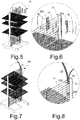
- the containers 420, 430 also house electrical terminals 421, 431 of the rigid electric conductors 42, 43, which are preferably of the type with a retractable pin biased by a helical spring as shown in the detailed view of figure 4.
- Figure 4 only shows one electrical conductor 42 in its container 420 made of an insulating material. The electrical conductor is shown by way of dot and dashed lines.
- containers made of an electrically insulating material for the electrical conductors 42, 43 advantageously provides a higher protection to a user against accidental contact with the electric components of a lighting set, as well as of a higher flexural rigidity that contributes to make the assembly of the lamps 40, 41 more simple and effective.
- the rigid electrical conductors 42, 43 with their possible containers 420, 430 made of an insulating material may be removably restrained to the supporting surfaces 21 of the shelves 20 or at their arms 22, 23 for example by means of hooks, guides, magnets or equivalent means (not shown).
- the containers 420, 430 include one or more openings or windows 422, 432 through which the rigid electric conductors 42, 43 are accessible so as to allow electrical connection of the lamps 40, 41.
- the openings 422, 432 are configured for the mechanical connection, e.g. a snap connection, of the ends of the lamps 40, 41 at which their electrical terminals are arranged.
- the lamps comprise mounting elements, for example jaw-shaped members, whose shape matches the shape of the rigid electric conductors 42, 43 housed in the containers 420, 430.
- the electrical terminals of the lamps 40, 41 face outwards from their mounting elements, so that when mounting a lamp on the electrical conductors 42, 43 housed in the containers 420, 430 mechanical connection and electrical connection are simultaneously achieved.
- the conductive strips 32, 33 are mounted on the panel element 14 not directly, but through respective guides 320, 330, for example rail-shaped guides.
- both the conductive strips 32, 33 and the guides 320, 330 are respectively made up of a plurality of sectors configured to be assembled to each other in the vertical direction V.
- the sectors of the guides 320, 330 are e.g. mounted in pairs on opposite faces of the panel element 14 and fixed to one another e.g. by way of pins.
- the connection between the guide sectors, as well as between the sectors of the conductive strips in the vertical direction V may for example be carried out by way of snap hooks.
- This configuration has the advantage of making the structure of the conductive strips and the respective guides modular and thus less cumbersome and more easily maneuverable, which allows to apply the lighting set not only to new shelving units, but also in already existing ones without being obliged to disassemble them.
- the conductive strips 32, 33 are formed by co-molding or co-injection of electrically conductive materials on flexible substrates, such as plastic sheets, and the assembly of the conductive strips on the guides is carried out by slidably fitting them on a plurality of supports 340 configured to be mounted at discrete positions of a panel element 14 of a shelving unit 10, wherein mounting may e.g. be carried out by snap fitting the supports into meshes of the panel element 14 when the latter is made up of a metal wire web as in the embodiment shown in figures 1 to 11 .
- this one is advantageous un that it makes the structure of the conductive strips and the respective supporting elements modular, thus allowing application of the lighting set not only to new shelving units, but also to already existing ones without being obliged to disassemble them.
- the conductive strips 32, 33 are formed by co-molding or co-injection molding of electrically conductive material on guides 320, 330 configured to be fitted into respective cavities of the uprights 12, 13 of a shelving unit 10, typically in the form of hollow metallic profiles having a rectangular or square cross-section.
- the guides 320, 330 may for example have a cross-section in the shape of an H.
- the containers 420, 430 made of electrically insulating material, housing the rigid electrical conductors 42, 43 to be connected to the electrical terminals 421, 431 that allow to power the lamps 40, 41, are configured to be removably connected to the arms 22, 23 of the shelves 20, for example by way of hooks, guides or equivalent means (not shown), so that the electrical terminals 421, 431 may be connected to the conductive strips 32, 33 housed in the uprights 12, 13 through the apertures 120, 130 for the mounting of the shelves 20 formed in the uprights.
- FIG. 9 only one side of the shelving unit 10 is shown. However, it will be appreciated that the opposite side of the shelving unit 10 has the same features as far as the conductive strips, the guides and the arrangement of the electrical conductors, the respective containers and the contact terminals are concerned.
- the guides 320, 330 of the conductive strips 32, 33 may be made up of modular sectors or be single bodies made of flexible materials, in order to facilitate their fitting into the uprights 12, 13.
- This configuration is particularly advantageous when the shelves mounted on the uprights contact the panel element, as it typically occurs in sheet metal shelving units, wherein there is no room for arranging the conductive strips and their supports on the panel element in the vertical direction.
- the rigid electric conductors 42, 43 are configured not only for the mechanical assembly and the powering of the lamps, but also for the powering of a label holder profile associated to a shelf.
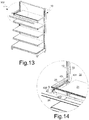
- the shelving unit 10 comprises a base 11, a pair of uprights 12, 13 extending perpendicularly from the base 11 in a substantially vertical direction V and a panel element 14.
- a plurality of apertures 120, 130 e.g. having a substantially slotted shape are formed along the uprights 12, 13 so as to allow mounting of a plurality of shelves 20.
- the shelves 20 In an assembled configuration, the shelves 20 extend perpendicularly to the panel element 14 in the transverse direction T.
- Each shelf 20 includes a supporting surface 21 for objects and/or products to be displayed and a pair of arms 22, 23 which hold the supporting surface 21.
- the ends of the arms 22, 23 intended to be anchored to the uprights 12, 13 are hook shaped so as to engage the apertures 120, 130 formed therein.
- the arms 22, 23 of the shelves 20 protrude from the uprights 12, 13 in the transverse direction T.
- Each shelf 20 also includes a label holder profile 24 that is restrained in a known manner at the free end of the supporting surface 21 and extends in the longitudinal direction L between the arms 22, 23.
- the rigid electrical conductors 42, 43 are flat bars, e.g. having a rectangular cross-section, accommodated in containers 420, 430 made of an insulating material.
- the electrical conductors and their respective containers made of an insulating material may be removably mounted by way of hooks, guides, magnets, or equivalent means.
- Figures 14 and 15 particularly show only the electric conductor 43 and the respective container 430 arranged close to the arm 23 of the shelf 20. It will be appreciated that the electrical conductor 42 and the respective container 420 that are arranged at the opposite end of the shelf 20 in the longitudinal direction L are identical to the electric conductor 43 and its container 430.
- the rigid electrical conductors 42, 43 are electrically connected to the conductive strips 32, 33 through respective electrical terminals 421, 431.
- the containers 420, 430 include one or more openings or windows 422, 432 through which the rigid electric conductors 42, 43 are accessible.
- the free ends of the rigid electric conductors 42, 43 are respectively electrically connected to a pair of strips 241, 242 made of a conductive material that are housed or integrally formed in the label holder profile 24.
- This allows powering of electronic labels (not shown) through the same power supply circuit of the lamps without resorting to respective batteries, which provides the advantage of a cheaper operation of the shelving unit, as well as of a lower environmental impact.
- the strips 241, 242 made of a conductive material extend between opposite ends of the label holder profile in the longitudinal direction L.
- the electrical connection between the rigid electric conductors 42, 43 and the strips 241, 242 made of a conductive material may for example be achieved by way of respective wires 243 and metal plates 244 associated with terminal elements 245 arranged at the ends of the label holder profile 24, or by way of equivalent solutions that are within the reach of a person skill in the art.
Landscapes
- Arrangement Of Elements, Cooling, Sealing, Or The Like Of Lighting Devices (AREA)
- Non-Portable Lighting Devices Or Systems Thereof (AREA)
Claims (7)
- Eine Regaleinheit (10), umfassend eine tragende Struktur und eine Mehrzahl von Einlegeböden (20), wobei die tragende Struktur einen Sockel (11) aufweist, ein Paar von Pfosten (12, 13), welche sich ausgehend von dem Sockel (11) in einer vertikalen Richtung (V) erstrecken, sowie ein Plattenelement (14), das zwischen den besagten Pfosten (12, 13) angeordnet ist, wobei die Pfosten (12, 13) eine Mehrzahl an Öffnungen (120, 130) mit einer substantiell schlitzförmigen Gestalt aufweisen, welche dafür ausgelegt sind, die Montage der besagten Einlegeböden (20) zu ermöglichen, und wobei jeder Einlegeboden (20) eine Auflagefläche (21) und ein Paar von Armen (22, 23) aufweist, welche die Auflagefläche (21) halten und von den Pfosten (12, 13) in einer transversalen Richtung (T) senkrecht zu der vertikalen Richtung (V) hervorstehen, wobei die besagte Regaleinheit (10) zusätzlich eine Beleuchtungsanlage zur Beleuchtung von Einlegeböden (20) aufweist, wobei die Beleuchtungsanlage ein Paar von Leiterbahnen (32, 33) aufweist, die an dem positiven bzw. negativen Pol eines Niederspannungtransformators (30) angeschlossen oder anschließbar sind, der von dem öffentlichen Stromversorgungsnetz gespeist werden kann, wobei sich die besagten Leiterbahnen (32, 33) in der besagten vertikalen Richtung (V) neben jedem Pfosten (12, 13) erstrecken, und wobei die Beleuchtungsanlage ferner wenigstens einen Leuchtkörper (40, 41) aufweist,
wobei die Beleuchtungsanlage für jeden zu beleuchtenden Regalboden (20) auch ein einzelnes Paar von starren elektrischen Leitern (42, 43) aufweist, welches derart konfiguriert ist, dass es an dem Regalboden (20) lösbar montiert ist,
wobei der besagte, wenigstens eine Leuchtkörper (40, 41) elektrische Anschlüsse an seinen Enden aufweist, die für einen Anschluss an die besagten elektrischen Leiter (42, 43) ausgelegt sind,
wobei die Gesamtanordnung der Regaleinheit (10) derart getroffen ist, dass der Leuchtkörper (40, 41) im zusammengebauten Zustand an den starren elektrischen Leitern (42, 43) elektrisch angeschlossen und mechanisch befestigt ist,
und wobei die besagten starren elektrischen Leiter (42, 43) von der Auflagefläche (21) des Regalbodens (20) oder entlang der Arme (22, 23) festgehalten werden und sich von den Leiterbahnen (32, 33) in einer transversalen Richtung (T), senkrecht zur vertikalen Richtung (V) und zu dem Plattenelement (14), ausdehnen, und wobei der wenigstens eine Leuchtkörper (40, 41) in einer Längsrichtung (L) rechtwinklig zu der vertikalen Richtung (V) und zu der transversalen Richtung (T) und parallel zu dem Plattenelement (14) angeordnet ist. - Eine Regaleinheit (10) gemäß Anspruch 1, wobei die starren elektrischen Leiter (42, 43) in entsprechenden Behältern (420, 430) untergebracht sind, wobei die Behälter (420, 430) eine oder mehr Öffnungen (422, 432) umfassen, durch welche die elektrischen Leiter (42, 43) zugänglich sind, um einen elektrischen Anschluss der Leuchtkörper (40, 41) zu ermöglichen.
- Eine Regaleinheit (10) gemäß Anspruch 2, wobei die Leuchtkörper (40, 41) ein Anschlussmittel aufweisen, das an ihren entsprechenden elektrischen Anschlüssen angeordnet ist, wobei das besagte Anschlussmittel derart ausgelegt ist, dass es die Montage der Leuchtkörper (40, 41) an den starren elektrischen Leitern (42, 43) bei den Öffnungen (422, 432) der Behälter (420, 430) aus elektrisch isolierendem Material ermöglicht.
- Eine Regaleinheit (10) gemäß einem der Ansprüche 1 bis 3, wobei die Leiterbahnen (32, 33) an dem Plattenelement (14) mttels entsprechender Führungen (320, 330) montiert oder montierbar sind, und wobei sowohl die Leiterbahnen (32, 33) wie auch die besagten Führungen (320, 330) aus einer Mehrzahl von Abschnitten bestehen, welche für einen gegenseitigen Zusammenbau konfiguriert sind.
- Eine Regaleinheit (10) gemäß einem der Ansprüche 1 bis 3, wobei die Leiterbahnen (32, 33) mittels Zusammenformen oder gemeinsamen Spritzgießens von elektrisch leitenden Materialien auf elastischen Trägern hergestellt sind, wobei die besagten Träger an einer Mehrzahl von Tragelementen (340) verschiebbar gelagert oder lagerbar sind, welche an diskreten Stellen des Plattenelements (14) befestigt sind.
- Eine Regaleinheit (10) gemäß einem der Ansprüche 1 bis 5, wobei jeder Einlegeboden (20) auch ein Etikettenhalteprofil (24) aufweist, das am freien Ende seiner Auflagefläche (21) festgehalten ist und sich in der Längsrichtung (L) zwischen seinen Armen (22, 23) erstreckt, und wobei die freien Enden der starren elektrischen Leiter (42, 43) jeweils an einem Paar von Streifen (241, 242) aus einem leitfähigen Material elektrisch angeschlossen sind, wobei die besagten Streifen in dem Etikettenhalteprofil (24) aufgenommen oder integral eingearbeitet sind und sich entlang des Etikettenhalteprofils (24) zwischen seinen entgegengesetzten Enden erstrecken.
- Eine Regaleinheit (10) gemäß Anspruch 6, wobei die starren elektrischen Leiter (42, 43) an dem Paar von Streifen (241, 242) aus einem leitfähigen Material elektrisch angeschlossen sind mittels entsprechenden Drähten (243) oder Metallplatten (244), die mit an den Enden des Etikettenhalteprofils (24) angeordneten Anschlüssen (245) verbunden sind.
Applications Claiming Priority (1)
| Application Number | Priority Date | Filing Date | Title |
|---|---|---|---|
| ITUB20150296 | 2015-03-31 |
Publications (2)
| Publication Number | Publication Date |
|---|---|
| EP3075285A1 EP3075285A1 (de) | 2016-10-05 |
| EP3075285B1 true EP3075285B1 (de) | 2018-05-16 |
Family
ID=53442906
Family Applications (1)
| Application Number | Title | Priority Date | Filing Date |
|---|---|---|---|
| EP16159602.8A Active EP3075285B1 (de) | 2015-03-31 | 2016-03-10 | Regaleinheit mit beleuchteten regalen |
Country Status (2)
| Country | Link |
|---|---|
| EP (1) | EP3075285B1 (de) |
| ES (1) | ES2683646T3 (de) |
Families Citing this family (9)
| Publication number | Priority date | Publication date | Assignee | Title |
|---|---|---|---|---|
| US10537191B2 (en) * | 2015-08-27 | 2020-01-21 | Walgreen Co. | Illuminated shelf system with electrical supply rails affixed to wall panel |
| MX2019007888A (es) * | 2016-12-30 | 2020-01-15 | Walmart Apollo Llc | Sistema de repisa modular intercambiable. |
| DE102017107942A1 (de) * | 2017-04-12 | 2018-10-18 | Rehau Ag + Co | System zur Bestromung mehrerer elektronischer Anzeigeeinrichtungen zur Anzeige von produktbezogenen Informationen und Warenpräsentationssystem |
| CN108461047B (zh) * | 2018-03-28 | 2023-08-29 | 上特展示(厦门)股份有限公司 | 展示架上显示物品信息的lcd显示屏结构及装置 |
| US10939756B2 (en) * | 2018-06-22 | 2021-03-09 | Product Miniature, Inc. | Modular shelf system |
| US11592879B2 (en) * | 2019-07-26 | 2023-02-28 | Artitalia Group Inc. | Modular back panel assembly for a display structure |
| CN110566856B (zh) * | 2019-10-14 | 2024-03-12 | 江苏优为视界科技有限公司 | 一种多回路低压轨道灯具连接机构 |
| WO2021141555A1 (en) * | 2020-01-09 | 2021-07-15 | Üçge Mağaza Eki̇pmanlari Pazarlama Sanayi̇ Ve Ti̇caret Anoni̇m Şi̇rketi̇ | Shelf electricity conduction apparatus |
| KR102503425B1 (ko) * | 2021-10-19 | 2023-02-24 | 주식회사 쿠스코 | 조명이 구비된 선반을 포함하는 시스템 가구 |
Citations (1)
| Publication number | Priority date | Publication date | Assignee | Title |
|---|---|---|---|---|
| US20140055987A1 (en) * | 2012-08-22 | 2014-02-27 | Streater LLC | Shelving Unit Lighting System |
Family Cites Families (9)
| Publication number | Priority date | Publication date | Assignee | Title |
|---|---|---|---|---|
| US3248494A (en) * | 1963-08-05 | 1966-04-26 | L P T Systems Inc | Combination switch and bulb mounting |
| GB9221946D0 (en) | 1992-10-17 | 1992-12-02 | Sharp John C | Display lighting |
| FR2731885B1 (fr) * | 1995-03-23 | 1997-06-06 | Piepszownik Marc | Installation d'etageres demontables |
| FR2745108B1 (fr) * | 1996-02-15 | 1998-04-10 | Cqfd | Dispositif signaletique pour tablette |
| US6231205B1 (en) | 1998-10-23 | 2001-05-15 | Powerwall, Inc. | Illuminated shelving |
| JP2012040334A (ja) * | 2010-08-19 | 2012-03-01 | Takafumi Takeuchi | 陳列棚の照明装置 |
| JP2014166201A (ja) | 2013-02-28 | 2014-09-11 | Takafumi Takeuchi | 棚照明装置 |
| CN203466400U (zh) | 2013-08-29 | 2014-03-05 | 东莞恒隆家具制造有限公司 | 一种用于展示行业的发光系统通电装置 |
| DE202014002269U1 (de) | 2014-03-12 | 2014-04-14 | Diode-On Optoelectronics Limited | Präsentationsständer |
-
2016
- 2016-03-10 ES ES16159602.8T patent/ES2683646T3/es active Active
- 2016-03-10 EP EP16159602.8A patent/EP3075285B1/de active Active
Patent Citations (1)
| Publication number | Priority date | Publication date | Assignee | Title |
|---|---|---|---|---|
| US20140055987A1 (en) * | 2012-08-22 | 2014-02-27 | Streater LLC | Shelving Unit Lighting System |
Also Published As
| Publication number | Publication date |
|---|---|
| EP3075285A1 (de) | 2016-10-05 |
| ES2683646T3 (es) | 2018-09-27 |
Similar Documents
| Publication | Publication Date | Title |
|---|---|---|
| EP3075285A1 (de) | Regaleinheit mit beleuchtete regale | |
| US10542828B2 (en) | Modular wall assembly for a cosmetic fixture system | |
| DE69714729T2 (de) | Bausatzmöbel mit integriertem netzanschluss | |
| US9537274B1 (en) | Modular power and connector system for lighting elements | |
| EP3341655B1 (de) | Beleuchtetes regalsystem | |
| EP2821695A1 (de) | Baugruppe aus einer Spannungsschiene, einem Adapter und einer LED-Röhre, Adapter für diese Baugruppe und Verfahren zur Montage von Leuchtkörpern | |
| AU2021229208A1 (en) | Low voltage power system for a merchandise display | |
| AU2015233672A1 (en) | Partition wall element and partition wall | |
| EP2077416A2 (de) | Beleuchtungseinrichtung mit einer selbsttragenden flexiblen Struktur | |
| JP2014166201A (ja) | 棚照明装置 | |
| CN107874530A (zh) | 特别是用于商品的展示装置 | |
| WO2015015187A1 (en) | A shelf power distribution apparatus | |
| EP4420559B1 (de) | Systemmöbel mit regalen mit beleuchtung | |
| ES2264984T3 (es) | Dispositivo de iluminacion para una vitrina. | |
| KR20140105244A (ko) | 찬넬 콘센트 와 플러그를 구성한 찬넬 지주장치 | |
| KR100782385B1 (ko) | 엘이디 조명기구 진열장 | |
| GB2355298A (en) | Modular framework comprising a plurality of releasably-connected light fitting supports | |
| WO2024079652A1 (en) | Shelf support system | |
| EP2901896A1 (de) | Modulares Präsentationsregalsystem | |
| CN211625168U (zh) | 一种用于移动灯具的导轨 | |
| EP2106726B1 (de) | Regalanordnung | |
| EP3323317B1 (de) | Schaukasten, insbesondere für laden | |
| NL1017243C1 (nl) | Afdekraam-systeem voor elektrische installatie-toestellen. | |
| CN212346071U (zh) | 展柜照明单元以及展柜 | |
| KR101227948B1 (ko) | 진열장 조립체 |
Legal Events
| Date | Code | Title | Description |
|---|---|---|---|
| PUAI | Public reference made under article 153(3) epc to a published international application that has entered the european phase |
Free format text: ORIGINAL CODE: 0009012 |
|
| AK | Designated contracting states |
Kind code of ref document: A1 Designated state(s): AL AT BE BG CH CY CZ DE DK EE ES FI FR GB GR HR HU IE IS IT LI LT LU LV MC MK MT NL NO PL PT RO RS SE SI SK SM TR |
|
| AX | Request for extension of the european patent |
Extension state: BA ME |
|
| STAA | Information on the status of an ep patent application or granted ep patent |
Free format text: STATUS: REQUEST FOR EXAMINATION WAS MADE |
|
| 17P | Request for examination filed |
Effective date: 20170331 |
|
| RBV | Designated contracting states (corrected) |
Designated state(s): AL AT BE BG CH CY CZ DE DK EE ES FI FR GB GR HR HU IE IS IT LI LT LU LV MC MK MT NL NO PL PT RO RS SE SI SK SM TR |
|
| GRAP | Despatch of communication of intention to grant a patent |
Free format text: ORIGINAL CODE: EPIDOSNIGR1 |
|
| STAA | Information on the status of an ep patent application or granted ep patent |
Free format text: STATUS: GRANT OF PATENT IS INTENDED |
|
| INTG | Intention to grant announced |
Effective date: 20171011 |
|
| GRAS | Grant fee paid |
Free format text: ORIGINAL CODE: EPIDOSNIGR3 |
|
| GRAA | (expected) grant |
Free format text: ORIGINAL CODE: 0009210 |
|
| STAA | Information on the status of an ep patent application or granted ep patent |
Free format text: STATUS: THE PATENT HAS BEEN GRANTED |
|
| AK | Designated contracting states |
Kind code of ref document: B1 Designated state(s): AL AT BE BG CH CY CZ DE DK EE ES FI FR GB GR HR HU IE IS IT LI LT LU LV MC MK MT NL NO PL PT RO RS SE SI SK SM TR |
|
| REG | Reference to a national code |
Ref country code: GB Ref legal event code: FG4D |
|
| REG | Reference to a national code |
Ref country code: CH Ref legal event code: EP |
|
| REG | Reference to a national code |
Ref country code: IE Ref legal event code: FG4D |
|
| REG | Reference to a national code |
Ref country code: DE Ref legal event code: R096 Ref document number: 602016003041 Country of ref document: DE |
|
| REG | Reference to a national code |
Ref country code: AT Ref legal event code: REF Ref document number: 998760 Country of ref document: AT Kind code of ref document: T Effective date: 20180615 |
|
| REG | Reference to a national code |
Ref country code: SE Ref legal event code: TRGR |
|
| REG | Reference to a national code |
Ref country code: NL Ref legal event code: MP Effective date: 20180516 |
|
| REG | Reference to a national code |
Ref country code: ES Ref legal event code: FG2A Ref document number: 2683646 Country of ref document: ES Kind code of ref document: T3 Effective date: 20180927 |
|
| REG | Reference to a national code |
Ref country code: LT Ref legal event code: MG4D |
|
| PG25 | Lapsed in a contracting state [announced via postgrant information from national office to epo] |
Ref country code: BG Free format text: LAPSE BECAUSE OF FAILURE TO SUBMIT A TRANSLATION OF THE DESCRIPTION OR TO PAY THE FEE WITHIN THE PRESCRIBED TIME-LIMIT Effective date: 20180816 Ref country code: FI Free format text: LAPSE BECAUSE OF FAILURE TO SUBMIT A TRANSLATION OF THE DESCRIPTION OR TO PAY THE FEE WITHIN THE PRESCRIBED TIME-LIMIT Effective date: 20180516 Ref country code: NO Free format text: LAPSE BECAUSE OF FAILURE TO SUBMIT A TRANSLATION OF THE DESCRIPTION OR TO PAY THE FEE WITHIN THE PRESCRIBED TIME-LIMIT Effective date: 20180816 Ref country code: LT Free format text: LAPSE BECAUSE OF FAILURE TO SUBMIT A TRANSLATION OF THE DESCRIPTION OR TO PAY THE FEE WITHIN THE PRESCRIBED TIME-LIMIT Effective date: 20180516 |
|
| PG25 | Lapsed in a contracting state [announced via postgrant information from national office to epo] |
Ref country code: GR Free format text: LAPSE BECAUSE OF FAILURE TO SUBMIT A TRANSLATION OF THE DESCRIPTION OR TO PAY THE FEE WITHIN THE PRESCRIBED TIME-LIMIT Effective date: 20180817 Ref country code: HR Free format text: LAPSE BECAUSE OF FAILURE TO SUBMIT A TRANSLATION OF THE DESCRIPTION OR TO PAY THE FEE WITHIN THE PRESCRIBED TIME-LIMIT Effective date: 20180516 Ref country code: LV Free format text: LAPSE BECAUSE OF FAILURE TO SUBMIT A TRANSLATION OF THE DESCRIPTION OR TO PAY THE FEE WITHIN THE PRESCRIBED TIME-LIMIT Effective date: 20180516 Ref country code: NL Free format text: LAPSE BECAUSE OF FAILURE TO SUBMIT A TRANSLATION OF THE DESCRIPTION OR TO PAY THE FEE WITHIN THE PRESCRIBED TIME-LIMIT Effective date: 20180516 Ref country code: RS Free format text: LAPSE BECAUSE OF FAILURE TO SUBMIT A TRANSLATION OF THE DESCRIPTION OR TO PAY THE FEE WITHIN THE PRESCRIBED TIME-LIMIT Effective date: 20180516 |
|
| PG25 | Lapsed in a contracting state [announced via postgrant information from national office to epo] |
Ref country code: CZ Free format text: LAPSE BECAUSE OF FAILURE TO SUBMIT A TRANSLATION OF THE DESCRIPTION OR TO PAY THE FEE WITHIN THE PRESCRIBED TIME-LIMIT Effective date: 20180516 Ref country code: RO Free format text: LAPSE BECAUSE OF FAILURE TO SUBMIT A TRANSLATION OF THE DESCRIPTION OR TO PAY THE FEE WITHIN THE PRESCRIBED TIME-LIMIT Effective date: 20180516 Ref country code: DK Free format text: LAPSE BECAUSE OF FAILURE TO SUBMIT A TRANSLATION OF THE DESCRIPTION OR TO PAY THE FEE WITHIN THE PRESCRIBED TIME-LIMIT Effective date: 20180516 Ref country code: EE Free format text: LAPSE BECAUSE OF FAILURE TO SUBMIT A TRANSLATION OF THE DESCRIPTION OR TO PAY THE FEE WITHIN THE PRESCRIBED TIME-LIMIT Effective date: 20180516 Ref country code: PL Free format text: LAPSE BECAUSE OF FAILURE TO SUBMIT A TRANSLATION OF THE DESCRIPTION OR TO PAY THE FEE WITHIN THE PRESCRIBED TIME-LIMIT Effective date: 20180516 Ref country code: SK Free format text: LAPSE BECAUSE OF FAILURE TO SUBMIT A TRANSLATION OF THE DESCRIPTION OR TO PAY THE FEE WITHIN THE PRESCRIBED TIME-LIMIT Effective date: 20180516 |
|
| REG | Reference to a national code |
Ref country code: DE Ref legal event code: R097 Ref document number: 602016003041 Country of ref document: DE |
|
| PG25 | Lapsed in a contracting state [announced via postgrant information from national office to epo] |
Ref country code: SM Free format text: LAPSE BECAUSE OF FAILURE TO SUBMIT A TRANSLATION OF THE DESCRIPTION OR TO PAY THE FEE WITHIN THE PRESCRIBED TIME-LIMIT Effective date: 20180516 |
|
| PLBE | No opposition filed within time limit |
Free format text: ORIGINAL CODE: 0009261 |
|
| STAA | Information on the status of an ep patent application or granted ep patent |
Free format text: STATUS: NO OPPOSITION FILED WITHIN TIME LIMIT |
|
| 26N | No opposition filed |
Effective date: 20190219 |
|
| PG25 | Lapsed in a contracting state [announced via postgrant information from national office to epo] |
Ref country code: SI Free format text: LAPSE BECAUSE OF FAILURE TO SUBMIT A TRANSLATION OF THE DESCRIPTION OR TO PAY THE FEE WITHIN THE PRESCRIBED TIME-LIMIT Effective date: 20180516 |
|
| REG | Reference to a national code |
Ref country code: AT Ref legal event code: UEP Ref document number: 998760 Country of ref document: AT Kind code of ref document: T Effective date: 20180516 |
|
| PG25 | Lapsed in a contracting state [announced via postgrant information from national office to epo] |
Ref country code: MC Free format text: LAPSE BECAUSE OF FAILURE TO SUBMIT A TRANSLATION OF THE DESCRIPTION OR TO PAY THE FEE WITHIN THE PRESCRIBED TIME-LIMIT Effective date: 20180516 |
|
| REG | Reference to a national code |
Ref country code: CH Ref legal event code: PL |
|
| PG25 | Lapsed in a contracting state [announced via postgrant information from national office to epo] |
Ref country code: AL Free format text: LAPSE BECAUSE OF FAILURE TO SUBMIT A TRANSLATION OF THE DESCRIPTION OR TO PAY THE FEE WITHIN THE PRESCRIBED TIME-LIMIT Effective date: 20180516 Ref country code: LU Free format text: LAPSE BECAUSE OF NON-PAYMENT OF DUE FEES Effective date: 20190310 |
|
| REG | Reference to a national code |
Ref country code: BE Ref legal event code: MM Effective date: 20190331 |
|
| PG25 | Lapsed in a contracting state [announced via postgrant information from national office to epo] |
Ref country code: IE Free format text: LAPSE BECAUSE OF NON-PAYMENT OF DUE FEES Effective date: 20190310 Ref country code: LI Free format text: LAPSE BECAUSE OF NON-PAYMENT OF DUE FEES Effective date: 20190331 Ref country code: CH Free format text: LAPSE BECAUSE OF NON-PAYMENT OF DUE FEES Effective date: 20190331 |
|
| PG25 | Lapsed in a contracting state [announced via postgrant information from national office to epo] |
Ref country code: BE Free format text: LAPSE BECAUSE OF NON-PAYMENT OF DUE FEES Effective date: 20190331 |
|
| PG25 | Lapsed in a contracting state [announced via postgrant information from national office to epo] |
Ref country code: TR Free format text: LAPSE BECAUSE OF FAILURE TO SUBMIT A TRANSLATION OF THE DESCRIPTION OR TO PAY THE FEE WITHIN THE PRESCRIBED TIME-LIMIT Effective date: 20180516 |
|
| PG25 | Lapsed in a contracting state [announced via postgrant information from national office to epo] |
Ref country code: MT Free format text: LAPSE BECAUSE OF NON-PAYMENT OF DUE FEES Effective date: 20190310 Ref country code: PT Free format text: LAPSE BECAUSE OF FAILURE TO SUBMIT A TRANSLATION OF THE DESCRIPTION OR TO PAY THE FEE WITHIN THE PRESCRIBED TIME-LIMIT Effective date: 20180917 |
|
| GBPC | Gb: european patent ceased through non-payment of renewal fee |
Effective date: 20200310 |
|
| PG25 | Lapsed in a contracting state [announced via postgrant information from national office to epo] |
Ref country code: GB Free format text: LAPSE BECAUSE OF NON-PAYMENT OF DUE FEES Effective date: 20200310 |
|
| PGFP | Annual fee paid to national office [announced via postgrant information from national office to epo] |
Ref country code: FR Payment date: 20210330 Year of fee payment: 6 |
|
| PG25 | Lapsed in a contracting state [announced via postgrant information from national office to epo] |
Ref country code: CY Free format text: LAPSE BECAUSE OF FAILURE TO SUBMIT A TRANSLATION OF THE DESCRIPTION OR TO PAY THE FEE WITHIN THE PRESCRIBED TIME-LIMIT Effective date: 20180516 |
|
| PGFP | Annual fee paid to national office [announced via postgrant information from national office to epo] |
Ref country code: DE Payment date: 20210330 Year of fee payment: 6 Ref country code: AT Payment date: 20210331 Year of fee payment: 6 Ref country code: SE Payment date: 20210330 Year of fee payment: 6 |
|
| PG25 | Lapsed in a contracting state [announced via postgrant information from national office to epo] |
Ref country code: IS Free format text: LAPSE BECAUSE OF FAILURE TO SUBMIT A TRANSLATION OF THE DESCRIPTION OR TO PAY THE FEE WITHIN THE PRESCRIBED TIME-LIMIT Effective date: 20180916 |
|
| PG25 | Lapsed in a contracting state [announced via postgrant information from national office to epo] |
Ref country code: HU Free format text: LAPSE BECAUSE OF FAILURE TO SUBMIT A TRANSLATION OF THE DESCRIPTION OR TO PAY THE FEE WITHIN THE PRESCRIBED TIME-LIMIT; INVALID AB INITIO Effective date: 20160310 |
|
| PGFP | Annual fee paid to national office [announced via postgrant information from national office to epo] |
Ref country code: ES Payment date: 20210525 Year of fee payment: 6 |
|
| PG25 | Lapsed in a contracting state [announced via postgrant information from national office to epo] |
Ref country code: MK Free format text: LAPSE BECAUSE OF FAILURE TO SUBMIT A TRANSLATION OF THE DESCRIPTION OR TO PAY THE FEE WITHIN THE PRESCRIBED TIME-LIMIT Effective date: 20180516 |
|
| REG | Reference to a national code |
Ref country code: DE Ref legal event code: R119 Ref document number: 602016003041 Country of ref document: DE |
|
| REG | Reference to a national code |
Ref country code: AT Ref legal event code: MM01 Ref document number: 998760 Country of ref document: AT Kind code of ref document: T Effective date: 20220310 |
|
| PG25 | Lapsed in a contracting state [announced via postgrant information from national office to epo] |
Ref country code: SE Free format text: LAPSE BECAUSE OF NON-PAYMENT OF DUE FEES Effective date: 20220311 Ref country code: FR Free format text: LAPSE BECAUSE OF NON-PAYMENT OF DUE FEES Effective date: 20220331 Ref country code: DE Free format text: LAPSE BECAUSE OF NON-PAYMENT OF DUE FEES Effective date: 20221001 Ref country code: AT Free format text: LAPSE BECAUSE OF NON-PAYMENT OF DUE FEES Effective date: 20220310 |
|
| REG | Reference to a national code |
Ref country code: ES Ref legal event code: FD2A Effective date: 20230428 |
|
| PG25 | Lapsed in a contracting state [announced via postgrant information from national office to epo] |
Ref country code: ES Free format text: LAPSE BECAUSE OF NON-PAYMENT OF DUE FEES Effective date: 20220311 |
|
| PGFP | Annual fee paid to national office [announced via postgrant information from national office to epo] |
Ref country code: IT Payment date: 20250324 Year of fee payment: 10 |