EP3075475A1 - Cutting tool - Google Patents
Cutting tool Download PDFInfo
- Publication number
- EP3075475A1 EP3075475A1 EP14865641.6A EP14865641A EP3075475A1 EP 3075475 A1 EP3075475 A1 EP 3075475A1 EP 14865641 A EP14865641 A EP 14865641A EP 3075475 A1 EP3075475 A1 EP 3075475A1
- Authority
- EP
- European Patent Office
- Prior art keywords
- layer
- contained
- base
- content
- cutting tool
- Prior art date
- Legal status (The legal status is an assumption and is not a legal conclusion. Google has not performed a legal analysis and makes no representation as to the accuracy of the status listed.)
- Withdrawn
Links
- 238000005520 cutting process Methods 0.000 title claims abstract description 55
- 239000010410 layer Substances 0.000 claims abstract description 243
- 239000011247 coating layer Substances 0.000 claims abstract description 55
- 238000004458 analytical method Methods 0.000 claims abstract description 26
- 238000004993 emission spectroscopy Methods 0.000 claims abstract description 13
- PNEYBMLMFCGWSK-UHFFFAOYSA-N aluminium oxide Inorganic materials [O-2].[O-2].[O-2].[Al+3].[Al+3] PNEYBMLMFCGWSK-UHFFFAOYSA-N 0.000 claims description 43
- 229910052593 corundum Inorganic materials 0.000 claims description 43
- 229910001845 yogo sapphire Inorganic materials 0.000 claims description 43
- 229910052721 tungsten Inorganic materials 0.000 claims description 19
- 229910052742 iron Inorganic materials 0.000 claims description 16
- 229910052710 silicon Inorganic materials 0.000 claims description 16
- 229910002515 CoAl Inorganic materials 0.000 claims description 4
- 229910052782 aluminium Inorganic materials 0.000 claims description 4
- 239000003245 coal Substances 0.000 claims description 4
- 229910018072 Al 2 O 3 Inorganic materials 0.000 abstract 3
- 239000010936 titanium Substances 0.000 description 77
- 239000002585 base Substances 0.000 description 58
- 239000011651 chromium Substances 0.000 description 54
- 239000007789 gas Substances 0.000 description 45
- 238000000151 deposition Methods 0.000 description 29
- 230000008021 deposition Effects 0.000 description 27
- NRTOMJZYCJJWKI-UHFFFAOYSA-N Titanium nitride Chemical compound [Ti]#N NRTOMJZYCJJWKI-UHFFFAOYSA-N 0.000 description 19
- WEVYAHXRMPXWCK-UHFFFAOYSA-N Acetonitrile Chemical compound CC#N WEVYAHXRMPXWCK-UHFFFAOYSA-N 0.000 description 18
- 239000000470 constituent Substances 0.000 description 18
- XJDNKRIXUMDJCW-UHFFFAOYSA-J titanium tetrachloride Chemical compound Cl[Ti](Cl)(Cl)Cl XJDNKRIXUMDJCW-UHFFFAOYSA-J 0.000 description 17
- 230000003647 oxidation Effects 0.000 description 15
- 238000007254 oxidation reaction Methods 0.000 description 15
- 239000000843 powder Substances 0.000 description 15
- 230000001965 increasing effect Effects 0.000 description 12
- 239000000203 mixture Substances 0.000 description 12
- 239000000523 sample Substances 0.000 description 11
- VNWKTOKETHGBQD-UHFFFAOYSA-N methane Chemical compound C VNWKTOKETHGBQD-UHFFFAOYSA-N 0.000 description 10
- 239000007921 spray Substances 0.000 description 10
- 238000009826 distribution Methods 0.000 description 8
- 238000000034 method Methods 0.000 description 8
- 229910021555 Chromium Chloride Inorganic materials 0.000 description 6
- VSCWAEJMTAWNJL-UHFFFAOYSA-K aluminium trichloride Chemical compound Cl[Al](Cl)Cl VSCWAEJMTAWNJL-UHFFFAOYSA-K 0.000 description 6
- 238000005229 chemical vapour deposition Methods 0.000 description 6
- 229910052804 chromium Inorganic materials 0.000 description 6
- QSWDMMVNRMROPK-UHFFFAOYSA-K chromium(3+) trichloride Chemical compound [Cl-].[Cl-].[Cl-].[Cr+3] QSWDMMVNRMROPK-UHFFFAOYSA-K 0.000 description 6
- 239000001257 hydrogen Substances 0.000 description 6
- 229910052739 hydrogen Inorganic materials 0.000 description 6
- 125000004435 hydrogen atom Chemical class [H]* 0.000 description 6
- 229910052751 metal Inorganic materials 0.000 description 6
- 239000002184 metal Substances 0.000 description 6
- 239000002245 particle Substances 0.000 description 6
- 238000005245 sintering Methods 0.000 description 6
- IJGRMHOSHXDMSA-UHFFFAOYSA-N Atomic nitrogen Chemical compound N#N IJGRMHOSHXDMSA-UHFFFAOYSA-N 0.000 description 5
- UGFAIRIUMAVXCW-UHFFFAOYSA-N Carbon monoxide Chemical compound [O+]#[C-] UGFAIRIUMAVXCW-UHFFFAOYSA-N 0.000 description 5
- 229910052799 carbon Inorganic materials 0.000 description 5
- 229910002091 carbon monoxide Inorganic materials 0.000 description 5
- 239000013078 crystal Substances 0.000 description 5
- 230000003247 decreasing effect Effects 0.000 description 5
- 239000002002 slurry Substances 0.000 description 5
- 238000012360 testing method Methods 0.000 description 5
- 229910003470 tongbaite Inorganic materials 0.000 description 5
- CURLTUGMZLYLDI-UHFFFAOYSA-N Carbon dioxide Chemical compound O=C=O CURLTUGMZLYLDI-UHFFFAOYSA-N 0.000 description 4
- 238000000576 coating method Methods 0.000 description 4
- 230000000694 effects Effects 0.000 description 4
- 239000000463 material Substances 0.000 description 4
- 238000000465 moulding Methods 0.000 description 4
- 229910002092 carbon dioxide Inorganic materials 0.000 description 3
- 239000001569 carbon dioxide Substances 0.000 description 3
- 239000011248 coating agent Substances 0.000 description 3
- 230000007547 defect Effects 0.000 description 3
- 238000011156 evaluation Methods 0.000 description 3
- 238000000227 grinding Methods 0.000 description 3
- 238000005498 polishing Methods 0.000 description 3
- 238000012545 processing Methods 0.000 description 3
- 230000035939 shock Effects 0.000 description 3
- 238000003466 welding Methods 0.000 description 3
- VEXZGXHMUGYJMC-UHFFFAOYSA-N Hydrochloric acid Chemical compound Cl VEXZGXHMUGYJMC-UHFFFAOYSA-N 0.000 description 2
- 239000002173 cutting fluid Substances 0.000 description 2
- 238000005238 degreasing Methods 0.000 description 2
- 238000004453 electron probe microanalysis Methods 0.000 description 2
- 239000000839 emulsion Substances 0.000 description 2
- 230000002708 enhancing effect Effects 0.000 description 2
- 238000005530 etching Methods 0.000 description 2
- 239000012530 fluid Substances 0.000 description 2
- 238000010438 heat treatment Methods 0.000 description 2
- 238000005470 impregnation Methods 0.000 description 2
- 238000004519 manufacturing process Methods 0.000 description 2
- 238000005259 measurement Methods 0.000 description 2
- 238000002156 mixing Methods 0.000 description 2
- 239000002994 raw material Substances 0.000 description 2
- 238000004381 surface treatment Methods 0.000 description 2
- XLYOFNOQVPJJNP-UHFFFAOYSA-N water Substances O XLYOFNOQVPJJNP-UHFFFAOYSA-N 0.000 description 2
- OKTJSMMVPCPJKN-UHFFFAOYSA-N Carbon Chemical compound [C] OKTJSMMVPCPJKN-UHFFFAOYSA-N 0.000 description 1
- VYZAMTAEIAYCRO-UHFFFAOYSA-N Chromium Chemical compound [Cr] VYZAMTAEIAYCRO-UHFFFAOYSA-N 0.000 description 1
- RWSOTUBLDIXVET-UHFFFAOYSA-N Dihydrogen sulfide Chemical compound S RWSOTUBLDIXVET-UHFFFAOYSA-N 0.000 description 1
- 238000010306 acid treatment Methods 0.000 description 1
- 239000003513 alkali Substances 0.000 description 1
- 239000011230 binding agent Substances 0.000 description 1
- 239000003795 chemical substances by application Substances 0.000 description 1
- XBWRJSSJWDOUSJ-UHFFFAOYSA-L chromium(ii) chloride Chemical compound Cl[Cr]Cl XBWRJSSJWDOUSJ-UHFFFAOYSA-L 0.000 description 1
- 150000001875 compounds Chemical class 0.000 description 1
- 238000011109 contamination Methods 0.000 description 1
- 230000007797 corrosion Effects 0.000 description 1
- 238000005260 corrosion Methods 0.000 description 1
- 238000009792 diffusion process Methods 0.000 description 1
- 238000001035 drying Methods 0.000 description 1
- 238000000635 electron micrograph Methods 0.000 description 1
- 238000005469 granulation Methods 0.000 description 1
- 230000003179 granulation Effects 0.000 description 1
- 229910000041 hydrogen chloride Inorganic materials 0.000 description 1
- IXCSERBJSXMMFS-UHFFFAOYSA-N hydrogen chloride Substances Cl.Cl IXCSERBJSXMMFS-UHFFFAOYSA-N 0.000 description 1
- 239000012535 impurity Substances 0.000 description 1
- 150000002739 metals Chemical class 0.000 description 1
- 150000004767 nitrides Chemical class 0.000 description 1
- 239000003960 organic solvent Substances 0.000 description 1
- 230000000737 periodic effect Effects 0.000 description 1
- 238000005070 sampling Methods 0.000 description 1
- 239000002356 single layer Substances 0.000 description 1
- 238000009751 slip forming Methods 0.000 description 1
- 239000006104 solid solution Substances 0.000 description 1
- 239000000243 solution Substances 0.000 description 1
- 239000002904 solvent Substances 0.000 description 1
- 239000002344 surface layer Substances 0.000 description 1
- 229910052719 titanium Inorganic materials 0.000 description 1
Images

Classifications
-
- C—CHEMISTRY; METALLURGY
- C23—COATING METALLIC MATERIAL; COATING MATERIAL WITH METALLIC MATERIAL; CHEMICAL SURFACE TREATMENT; DIFFUSION TREATMENT OF METALLIC MATERIAL; COATING BY VACUUM EVAPORATION, BY SPUTTERING, BY ION IMPLANTATION OR BY CHEMICAL VAPOUR DEPOSITION, IN GENERAL; INHIBITING CORROSION OF METALLIC MATERIAL OR INCRUSTATION IN GENERAL
- C23C—COATING METALLIC MATERIAL; COATING MATERIAL WITH METALLIC MATERIAL; SURFACE TREATMENT OF METALLIC MATERIAL BY DIFFUSION INTO THE SURFACE, BY CHEMICAL CONVERSION OR SUBSTITUTION; COATING BY VACUUM EVAPORATION, BY SPUTTERING, BY ION IMPLANTATION OR BY CHEMICAL VAPOUR DEPOSITION, IN GENERAL
- C23C28/00—Coating for obtaining at least two superposed coatings either by methods not provided for in a single one of groups C23C2/00 - C23C26/00 or by combinations of methods provided for in subclasses C23C and C25C or C25D
- C23C28/04—Coating for obtaining at least two superposed coatings either by methods not provided for in a single one of groups C23C2/00 - C23C26/00 or by combinations of methods provided for in subclasses C23C and C25C or C25D only coatings of inorganic non-metallic material
- C23C28/044—Coating for obtaining at least two superposed coatings either by methods not provided for in a single one of groups C23C2/00 - C23C26/00 or by combinations of methods provided for in subclasses C23C and C25C or C25D only coatings of inorganic non-metallic material coatings specially adapted for cutting tools or wear applications
-
- B—PERFORMING OPERATIONS; TRANSPORTING
- B23—MACHINE TOOLS; METAL-WORKING NOT OTHERWISE PROVIDED FOR
- B23B—TURNING; BORING
- B23B27/00—Tools for turning or boring machines; Tools of a similar kind in general; Accessories therefor
- B23B27/14—Cutting tools of which the bits or tips or cutting inserts are of special material
-
- B—PERFORMING OPERATIONS; TRANSPORTING
- B23—MACHINE TOOLS; METAL-WORKING NOT OTHERWISE PROVIDED FOR
- B23C—MILLING
- B23C5/00—Milling-cutters
- B23C5/16—Milling-cutters characterised by physical features other than shape
-
- C—CHEMISTRY; METALLURGY
- C23—COATING METALLIC MATERIAL; COATING MATERIAL WITH METALLIC MATERIAL; CHEMICAL SURFACE TREATMENT; DIFFUSION TREATMENT OF METALLIC MATERIAL; COATING BY VACUUM EVAPORATION, BY SPUTTERING, BY ION IMPLANTATION OR BY CHEMICAL VAPOUR DEPOSITION, IN GENERAL; INHIBITING CORROSION OF METALLIC MATERIAL OR INCRUSTATION IN GENERAL
- C23C—COATING METALLIC MATERIAL; COATING MATERIAL WITH METALLIC MATERIAL; SURFACE TREATMENT OF METALLIC MATERIAL BY DIFFUSION INTO THE SURFACE, BY CHEMICAL CONVERSION OR SUBSTITUTION; COATING BY VACUUM EVAPORATION, BY SPUTTERING, BY ION IMPLANTATION OR BY CHEMICAL VAPOUR DEPOSITION, IN GENERAL
- C23C16/00—Chemical coating by decomposition of gaseous compounds, without leaving reaction products of surface material in the coating, i.e. chemical vapour deposition [CVD] processes
- C23C16/22—Chemical coating by decomposition of gaseous compounds, without leaving reaction products of surface material in the coating, i.e. chemical vapour deposition [CVD] processes characterised by the deposition of inorganic material, other than metallic material
- C23C16/30—Deposition of compounds, mixtures or solid solutions, e.g. borides, carbides, nitrides
- C23C16/308—Oxynitrides
-
- C—CHEMISTRY; METALLURGY
- C23—COATING METALLIC MATERIAL; COATING MATERIAL WITH METALLIC MATERIAL; CHEMICAL SURFACE TREATMENT; DIFFUSION TREATMENT OF METALLIC MATERIAL; COATING BY VACUUM EVAPORATION, BY SPUTTERING, BY ION IMPLANTATION OR BY CHEMICAL VAPOUR DEPOSITION, IN GENERAL; INHIBITING CORROSION OF METALLIC MATERIAL OR INCRUSTATION IN GENERAL
- C23C—COATING METALLIC MATERIAL; COATING MATERIAL WITH METALLIC MATERIAL; SURFACE TREATMENT OF METALLIC MATERIAL BY DIFFUSION INTO THE SURFACE, BY CHEMICAL CONVERSION OR SUBSTITUTION; COATING BY VACUUM EVAPORATION, BY SPUTTERING, BY ION IMPLANTATION OR BY CHEMICAL VAPOUR DEPOSITION, IN GENERAL
- C23C16/00—Chemical coating by decomposition of gaseous compounds, without leaving reaction products of surface material in the coating, i.e. chemical vapour deposition [CVD] processes
- C23C16/22—Chemical coating by decomposition of gaseous compounds, without leaving reaction products of surface material in the coating, i.e. chemical vapour deposition [CVD] processes characterised by the deposition of inorganic material, other than metallic material
- C23C16/30—Deposition of compounds, mixtures or solid solutions, e.g. borides, carbides, nitrides
- C23C16/34—Nitrides
-
- C—CHEMISTRY; METALLURGY
- C23—COATING METALLIC MATERIAL; COATING MATERIAL WITH METALLIC MATERIAL; CHEMICAL SURFACE TREATMENT; DIFFUSION TREATMENT OF METALLIC MATERIAL; COATING BY VACUUM EVAPORATION, BY SPUTTERING, BY ION IMPLANTATION OR BY CHEMICAL VAPOUR DEPOSITION, IN GENERAL; INHIBITING CORROSION OF METALLIC MATERIAL OR INCRUSTATION IN GENERAL
- C23C—COATING METALLIC MATERIAL; COATING MATERIAL WITH METALLIC MATERIAL; SURFACE TREATMENT OF METALLIC MATERIAL BY DIFFUSION INTO THE SURFACE, BY CHEMICAL CONVERSION OR SUBSTITUTION; COATING BY VACUUM EVAPORATION, BY SPUTTERING, BY ION IMPLANTATION OR BY CHEMICAL VAPOUR DEPOSITION, IN GENERAL
- C23C16/00—Chemical coating by decomposition of gaseous compounds, without leaving reaction products of surface material in the coating, i.e. chemical vapour deposition [CVD] processes
- C23C16/22—Chemical coating by decomposition of gaseous compounds, without leaving reaction products of surface material in the coating, i.e. chemical vapour deposition [CVD] processes characterised by the deposition of inorganic material, other than metallic material
- C23C16/30—Deposition of compounds, mixtures or solid solutions, e.g. borides, carbides, nitrides
- C23C16/36—Carbonitrides
-
- C—CHEMISTRY; METALLURGY
- C23—COATING METALLIC MATERIAL; COATING MATERIAL WITH METALLIC MATERIAL; CHEMICAL SURFACE TREATMENT; DIFFUSION TREATMENT OF METALLIC MATERIAL; COATING BY VACUUM EVAPORATION, BY SPUTTERING, BY ION IMPLANTATION OR BY CHEMICAL VAPOUR DEPOSITION, IN GENERAL; INHIBITING CORROSION OF METALLIC MATERIAL OR INCRUSTATION IN GENERAL
- C23C—COATING METALLIC MATERIAL; COATING MATERIAL WITH METALLIC MATERIAL; SURFACE TREATMENT OF METALLIC MATERIAL BY DIFFUSION INTO THE SURFACE, BY CHEMICAL CONVERSION OR SUBSTITUTION; COATING BY VACUUM EVAPORATION, BY SPUTTERING, BY ION IMPLANTATION OR BY CHEMICAL VAPOUR DEPOSITION, IN GENERAL
- C23C16/00—Chemical coating by decomposition of gaseous compounds, without leaving reaction products of surface material in the coating, i.e. chemical vapour deposition [CVD] processes
- C23C16/22—Chemical coating by decomposition of gaseous compounds, without leaving reaction products of surface material in the coating, i.e. chemical vapour deposition [CVD] processes characterised by the deposition of inorganic material, other than metallic material
- C23C16/30—Deposition of compounds, mixtures or solid solutions, e.g. borides, carbides, nitrides
- C23C16/40—Oxides
- C23C16/403—Oxides of aluminium, magnesium or beryllium
-
- C—CHEMISTRY; METALLURGY
- C23—COATING METALLIC MATERIAL; COATING MATERIAL WITH METALLIC MATERIAL; CHEMICAL SURFACE TREATMENT; DIFFUSION TREATMENT OF METALLIC MATERIAL; COATING BY VACUUM EVAPORATION, BY SPUTTERING, BY ION IMPLANTATION OR BY CHEMICAL VAPOUR DEPOSITION, IN GENERAL; INHIBITING CORROSION OF METALLIC MATERIAL OR INCRUSTATION IN GENERAL
- C23C—COATING METALLIC MATERIAL; COATING MATERIAL WITH METALLIC MATERIAL; SURFACE TREATMENT OF METALLIC MATERIAL BY DIFFUSION INTO THE SURFACE, BY CHEMICAL CONVERSION OR SUBSTITUTION; COATING BY VACUUM EVAPORATION, BY SPUTTERING, BY ION IMPLANTATION OR BY CHEMICAL VAPOUR DEPOSITION, IN GENERAL
- C23C28/00—Coating for obtaining at least two superposed coatings either by methods not provided for in a single one of groups C23C2/00 - C23C26/00 or by combinations of methods provided for in subclasses C23C and C25C or C25D
- C23C28/04—Coating for obtaining at least two superposed coatings either by methods not provided for in a single one of groups C23C2/00 - C23C26/00 or by combinations of methods provided for in subclasses C23C and C25C or C25D only coatings of inorganic non-metallic material
- C23C28/042—Coating for obtaining at least two superposed coatings either by methods not provided for in a single one of groups C23C2/00 - C23C26/00 or by combinations of methods provided for in subclasses C23C and C25C or C25D only coatings of inorganic non-metallic material including a refractory ceramic layer, e.g. refractory metal oxides, ZrO2, rare earth oxides
-
- B—PERFORMING OPERATIONS; TRANSPORTING
- B23—MACHINE TOOLS; METAL-WORKING NOT OTHERWISE PROVIDED FOR
- B23B—TURNING; BORING
- B23B2228/00—Properties of materials of tools or workpieces, materials of tools or workpieces applied in a specific manner
- B23B2228/10—Coatings
-
- B—PERFORMING OPERATIONS; TRANSPORTING
- B23—MACHINE TOOLS; METAL-WORKING NOT OTHERWISE PROVIDED FOR
- B23C—MILLING
- B23C2228/00—Properties of materials of tools or workpieces, materials of tools or workpieces applied in a specific manner
- B23C2228/10—Coating
Definitions
- the present invention relates to a cutting tool, and more particularly, to a cutting tool including a coating layer.
- bases such as cemented carbide with coating layers of multiple layers such as a TiCN layer and an Al 2 O 3 layer formed by deposition on the surfaces of the bases are widely used for cutting tools widely used for metal cutting work.
- the corrosion resistance of cemented carbide is enhanced by a Cr constituent contained in the cemented carbide, besides WC.
- Patent Document 1 discloses a cutting tool coated with a TiN layer, a TiCN layer, a TiC layer, a TiCNO layer, an Al 2 O 3 layer, and a TiN layer in order on the surface of a base by a CVD (chemical vapor deposition) method, where W and Co are diffused and contained at crystal grain boundaries of the TiN layer on the side closer to the base, the TiCN layer, and the TiC layer.
- CVD chemical vapor deposition
- Patent Document 2 discloses a method of diffusing a Co constituent as well as a Cr constituent in a base of cemented carbide into a Ti-based coating layer on the side closer to the base, thereby enhancing the oxidation resistance of the Ti-based coating layer.
- the cutting tool with W and Co diffused and contained in the coating layer as described in Patent Document 1 is likely to cause the oxidation of the coating layer to proceed, and thus has the possibility of decreasing the wear resistance of the coating layer.
- the cutting tool with Co and Cr diffused in the coating layer as described in Patent Document 2 has insufficient oxidation resistance at the surface of the coating layer.
- An object of the present invention is to provide a cutting tool which can inhibit the oxidation of a coating layer even in processing in which a cutting edge reaches high temperatures, such as high-speed cutting, thereby providing excellent wear resistance.
- the cutting tool according to the present embodiment contains Cr in the Ti-based layer, Al 2 O 3 layer, and outermost layer that coat the surface of the base of the cemented carbide, and the oxidation resistance of the coating layer is enhanced by adjusting the contents of Cr contained in the respective layers with respect to the content of Cr contained in the base so as to follow a predetermined order, and thereby the wear resistance of the cutting tool can be improved.
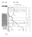
- FIG. 1(a) is a scanning electron microscope (SEM) photograph for a cross section including a coating layer of a cutting tool
- Fig. 1(b) shows a glow-discharge emission spectrometry (GDS analysis) for the depth direction from the surface of the coating layer
- FIG. 2 is a partial enlarged view for checking distribution of minor constituents in the GDS analysis data.
- FIGS. 1 and 2 specify the compositions of respective layers, which are determined by the correspondence between distribution of respective elements and the electron micrograph (SEM).
- Reference numeral 1 denotes a base (cemented carbide)
- reference numeral 4 denotes an intermediate layer
- the intermediate layer 4 can be omitted.
- the first Ti-based layer 2a on the side closer to the base 1 is a TiCN layer
- the second Ti-based layer 2b is also a TiCN layer that differs in CN ratio.
- the thickness of the respective layers can be calculated in the GDS analysis, thickness errors of the respective layers are increased when etching rate is different for every layer.
- the ranges of the respective layers were determined by confirming peak shapes of the GDS analysis data while checking the scanning electron microscope (SEM) photograph and electron probe microanalysis (EPMA) data (not shown).
- SEM scanning electron microscope
- EPMA electron probe microanalysis
- the thickness-center positions of the respective layers are identified as a center L Ti of the first Ti-based layer 2a and a center L A1 of the Al 2 O 3 layer 5.
- the intermediate layer 4 and the outermost layer 6 are determined by identifying the region of the Ti-based layer 2 composed of the first Ti-based layer 2a and the second Ti-based layer 2b and the region of the Al 2 O 3 layer 5, and as for the center positions of the intermediate layer 4 and outermost layer 6, the center positions in the regions are identified as the center positions (not shown).
- the boundaries between the corresponding layers are regarded as flexion points at which the contents of respective elements change sharply.
- the boundaries between the corresponding layers are identified by the following method. More specifically, the boundary between the region of the first Ti-based layer 2a and the region of the second Ti-based layer 2b is defined as a point at which the content of Ti is 10% lower with respect to the maximum of the Ti content in the region of the first Ti-based layer 2a.
- the boundary between the region of the second Ti-based layer 2b and the region of the intermediate layer 4 is defined as a point at which the content of Ti is 10% lower with respect to the maximum of the Ti content in the region of the second Ti-based layer 2b.
- the boundary between the region of the intermediate layer 4 and the region of the Al 2 O 3 layer 5 is defined as a point at which the content of A1 is 10% lower with respect to the maximum of the A1 content in the Al 2 O 3 layer 5.
- the coating layer has a wide measurement field on the order of 1 mm in an in-plane direction, and thus, when depressions and protrusions exist between each of the layers, constituents in other layers adjacent to the respective layers may be mixed and detected.
- the constituents contained in the base 1 are mixed in the region identified as the first Ti-based layer 2a on the side closer to the base in the GDS analysis.
- the constituents contained in the Ti-based layer 2 as a lower layer are mixed in the region identified as the intermediate layer 4 on the side closer to the base, and the constituents contained in the Al 2 O 3 layer 5 as an upper layer are mixed and detected in the region identified as the intermediate layer 4 on the surface side.
- the region of the intermediate layer 4 in the GDS analysis is observed widely more than the actual thickness observed in the SEM photograph.
- a preferred example of the base 1 is formed from a WC phase, a bonded phase, and if necessary, a B1-type solid solution phase. Further, the example contains WC in a proportion of 80 to 94 mass%, Co in a proportion of 5 to 15 mass%, Cr in a proportion of 0.1 to 1 mass% in terms of Cr 3 C 2 , and at least one of a carbide (excluding WC), a nitride, and a carbonitride of at least one selected from the group of metals in Groups 4, 5, and 6 of the periodic table, excluding Cr, in a proportion of 0 to 10 mass%.
- the coating layer 7 of the Ti-based layer 2, intermediate layer 4, Al 2 O 3 layer 5, and outermost layer 6 laminated in order from the side of the base 1 is provided on the surface of the base 1.
- the content of Cr contained at the thickness-center point of the first Ti-based layer 2a in the Ti-based layer 2 on the side closer to the base 1 is lower than the content of Cr contained in the base 1, and higher than the content of Cr contained at the thickness-center point of the Al 2 O 3 layer 5.
- the content of Cr contained at the thickness-center point of the outermost layer 6 is higher than the content of Cr contained at the thickness-center point of the Al 2 O 3 layer.
- the Al 2 O 3 layer 5 has the effect of improving the wear resistance, because the content of Cr is lower as compared with those in the other layers.
- the outermost layer 6 also has, because of containing Cr, the effect of enhancing the weld resistance at the surface of the coating layer 7.
- the oxidation of the coating layer 7 has a tendency to proceed.
- the content of Cr contained at the thickness-center point of the Al 2 O 3 layer 5 is equal to or higher than the content of Cr contained at the thickness-center point of the first Ti-based layer 2a or at the thickness-center point of the outermost layer 6, the wear resistance of the Al 2 O 3 layer 5 has a tendency to decrease.
- the content of Cr contained at the thickness-center point of the outermost layer 6 is equal to or lower than the content of Cr contained at the thickness-center point of the Al 2 O 3 layer 5, the weld resistance of the coating layer 7 has a tendency to decrease.
- the ratios of the contents of Cr contained at the thickness-center positions of the respective layers of the first Ti-based layer 2a, Al 2 O 3 layer 5, and outermost layer 6 to the content of Cr contained in the base 1 are respectively represented by Cr Ti , Cr A1 , and Cr s , the following conditions are met: 0.5 ⁇ Cr Ti ⁇ 0.9; 0.01 ⁇ Cr A1 ⁇ 0.2 ; and 0.4 ⁇ Cr s ⁇ 0.7.
- the content of Cr contained in the base 1 is measured in the region where the change rates of the W and C contents fall within 5% in the GDS analysis data.
- the coating layer 7 contains therein W and Co besides Cr.
- W Ti , W Al , W s , Co Ti , Co Al , and Co s when the ratios of the contents of W and Co contained in the respective layers of the first Ti-based layer 2a, Al 2 O 3 layer 5, and outermost layer 6 to the contents of W and Co contained in the base 1 are respectively represented by W Ti , W Al , W s , Co Ti , Co Al , and Co s , the following conditions are met: 0.05 ⁇ W Ti ⁇ 0.3; W Al ⁇ 0.01; W s ⁇ 0.01; 0.05 ⁇ Co Ti ⁇ 0.3; Co Al ⁇ 0.01; and Co s ⁇ 0.01.
- the W and Co which diffuse from the base 1 can diffuse into the Ti-based layer 2 to further enhance the adhesion between the base 1 and the coating layer 7.
- the W and Co are likely to be oxidized at high temperature, and thus hardly diffuse into the Al 2 O 3 layer 5 and the outermost layer 6, thereby making it possible to suppress the oxidation of the coating layer 7.
- the base 1 contains therein Si and Fe as unavoidable impurity constituents, which diffuse into the coating layer 7.
- Si Ti , Si Al , Si s , Fe Ti , Fe Al , and Fe s the ratios of the contents of Si and Fe contained in the respective layers of the first Ti-based layer 2a, Al 2 O 3 layer 5, and outermost layer 6 to the contents of Si and Fe contained in the base 1 are respectively represented by Si Ti , Si Al , Si s , Fe Ti , Fe Al , and Fe s .
- the following conditions are met: 0.05 ⁇ Si Ti ⁇ 0.4; Si Al ⁇ 0.01; Si s ⁇ 0.01; 0.05 ⁇ Fe Ti ⁇ 0.4; Fe Al ⁇ 0.01; and Fe s ⁇ 0.01.
- the Si and Fe which diffuse from the base 1 can diffuse into the Ti-based layer 2 to further enhance the adhesion between the base 1 and the coating layer 7.
- the Si and Fe are likely to be oxidized at high temperature, and thus hardly diffuse into the Al 2 O 3 layer 5 and the outermost layer 6, thereby making it possible to suppress the oxidation of the coating layer 7.
- the ratios of the contents of Si and Fe contained in the intermediate layer 4 to the contents of Si and Fe contained in the base 1 are respectively represented by Si m and Fe m , the following conditions are met: Si m ⁇ 0.05 and Fe m ⁇ 0.05. More specifically, the Si and Fe which diffuse from the base 1 hardly diffuse into the intermediate layer 4, thereby making it possible to suppress the oxidation of the coating layer 7.
- the base 1 and the coating layer 7 contain therein C (carbon).
- C Ti , C m , C Al , and C s the ratios of the contents of C contained in the respective layers of the first Ti-based layer 2a, intermediate layer 4, Al 2 O 3 layer 5, and outermost layer 6 to the content of C contained in the base 1 are respectively represented by C Ti , C m , C Al , and C s , the following conditions are met: 0.2 ⁇ C Ti ⁇ 0.7; 0.01 ⁇ C m ⁇ 0.18; C A1 ⁇ 0.01; and C s ⁇ 0.30.
- the adhesion between the base 1 and the coating layer 7 can be further enhanced by controlling the C content in the coating layer 7.
- a further desirable range of C Ti is 0.3 ⁇ C Ti ⁇ 0.6.
- the Ti-based layer 2 has the first Ti-based layer 2a on the side closer to the base 1 and the second Ti-based layer 2b which are both TiCN layers, and has the multiple layers laminated
- the Ti-based layer may be a single layer, or a multilayer of three or more layers. This composition makes it possible to easily adjust the degrees of diffusion of respective constituents of Cr, W, Co, Fe, Si, and C into the coating layer 7.
- a WC powder, a metal Co powder, a Cr 3 C 2 powder, and if necessary, a compound powder containing other metal constituent are prepared respectively in proportions of: 80 to 94 mass%; 5 to 15 mass%; 0.1 to 1 mass%; and 0 to 10 mass% or less.
- This prepared powders are, with the addition of a solvent thereto, subjected to mixing and grinding for a predetermined period of time, thereby providing slurry.
- This slurry is further mixed with the addition of a binder thereto, and the mixed power is subjected to granulation while drying the slurry with the use of a spray dryer or the like.
- molding is carried out by press molding into a shape of a cutting tool.
- the temperature in the sintering furnace is increased to a sintering temperature of 1380 to 1480°C for sintering for 1 to 1.5 hours in a reduced atmosphere of 20 to 2000 Pa, thereby making it possible to prepare a cemented carbide.
- the surface of the cemented carbide is subjected to polishing, and a cutting part is subjected to honing.
- the base of the cemented carbide is subjected to an acid treatment or an alkali treatment to remove contamination on the surface of the base, a solution is prepared which contains a Cr 3 C 2 powder or metal chromium (Cr), and the Cr constituent is attached to the surface of the base by a spray method, an impregnation method, or a coating method, thereby increasing the Cr concentration.
- the coating layer 2 is formed by a chemical vapor deposition (CVD) method on the surface of the base obtained.
- CVD chemical vapor deposition
- a TiN (titanium nitride) layer as a first Ti-based layer is formed on the surface of the base, if necessary.
- Preferred deposition conditions therefor include: the use of a mixed gas containing, as a mixed gas composition, a titanium tetrachloride (TiCl 4 ) gas in a proportion of 0.5 to 10 volume% and a nitrogen (N 2 ) gas in a proportion of 10 to 60 volume%, and including a hydrogen (H 2 ) gas as a balance; the deposition temperature from 800 to 940°C; and the pressure from 8 to 50 kPa.
- a mixed gas containing, as a mixed gas composition, a titanium tetrachloride (TiCl 4 ) gas in a proportion of 0.5 to 10 volume% and a nitrogen (N 2 ) gas in a proportion of 10 to 60 volume%, and including a hydrogen (H 2 ) gas as a balance
- the deposition temperature from 800 to 940°C
- the pressure from 8 to 50 kPa.
- a TiCN layer as a second Ti-based layer is formed on the top of the TiN layer.
- Deposition conditions therefor include: the use of a mixed gas containing, as a mixed gas composition, a titanium tetrachloride (TiCl 4 ) gas in a proportion of 0.5 to 10 volume%, a nitrogen (N 2 ) gas in a proportion of 1 to 60 volume%, and an acetonitrile (CH 3 CN) gas in a proportion of 0.1 to 3.0 volume%, and including a hydrogen (H 2 ) gas as a balance; the deposition temperature from 780 to 850°C; and the pressure from 5 to 25 kPa, and under the conditions, a MT (Moderate Temperature)-TiCN layer is deposited which is composed of so-called columnar crystals.
- the crystal widths of the columnar crystals can be adjusted by increasing or decreasing the flow rate of the acetonitrile (CH 3 CN) gas during the deposition. Then, a HT (High Temperature)-TiCN layer composed of so-called grained crystals is formed on the top of the MT-TiCN layer.
- CH 3 CN acetonitrile
- the HT-TiCN layer is deposited by switching to deposition conditions of: the use of a mixed gas containing a titanium tetrachloride (TiCl 4 ) gas in a proportion of 0.1 to 3 volume%, a nitrogen (N 2 ) gas in a proportion of 0 to 15 volume%, and a methane (CH 4 ) gas or an acetonitrile (CH 3 CN) gas in a proportion of 0.1 to 10 volume%, and including a hydrogen (H 2 ) gas as a balance; the deposition temperature from 900 to 1020°C; and the pressure from 5 to 40 kPa.
- TiCl 4 titanium tetrachloride
- N 2 nitrogen
- CH 3 CN methane
- H 2 hydrogen
- Specific deposition conditions for the deposition of the TiAlCNO layer include: as an example, the use of a mixed gas containing a titanium tetrachloride (TiCl 4 ) gas in a proportion of 0.1 to 3 volume%, a nitrogen (N 2 ) gas in a proportion of 1 to 15 volume%, a methane (CH 4 ) gas or an acetonitrile (CH 3 CN) gas in a proportion of 0.1 to 10 volume%, a carbon monoxide (CO) gas in a proportion of 0.5 to 3.0 volume%, and aluminum trichloride (AlCl 3 ) in a proportion of 0.5 to 3.0 volume%, and including a hydrogen (H 2 ) gas as a balance; the deposition temperature from 900 to 1020°C; and the pressure from 5 to 40 kPa.
- TiCl 4 titanium tetrachloride
- N 2 nitrogen
- CH 4 methane
- CH 3 CN acetonitrile
- CO carbon
- an ⁇ -type Al 2 O 3 layer is continuously formed.
- Specific deposition conditions include: as an example, the use of a mixed gas containing an aluminum trichloride (AlCl 3 ) gas in a proportion of 0. 5 to 5.0 volume%, a hydrogen chloride (HCl) gas in a proportion of 0.5 to 3.5 volume%, a carbon dioxide (CO 2 ) gas in a proportion of 0.5 to 5. 0 volume%, and a hydrogen sulfide (H 2 S) gas in a proportion of 0 to 0.5 volume%, and including a hydrogen (H 2 ) gas as a balance; the deposition temperature from 930 to 1010°C; and the pressure from 5 to 10 kPa.
- AlCl 3 aluminum trichloride
- HCl hydrogen chloride
- CO 2 carbon dioxide
- H 2 S hydrogen sulfide
- an outermost layer is deposited on the surface of the Al 2 O 3 layer.
- Specific deposition conditions in the case of depositing a TiN layer as the outermost layer include: the use of a mixed gas containing, as a mixed gas composition, a titanium tetrachloride (TiCl 4 ) gas in a proportion of 0.1 to 10 volume%, a chromium dichloride (CrCl 2 ) gas in a proportion of 0.005 to 0.025 volume%, and a nitrogen (N 2 ) gas in a proportion of 1 to 60 volume%, and including a hydrogen (H 2 ) gas as a balance; the deposition temperature from 855 to 1010°C; and the pressure from 10 to 85 kPa.
- TiCl 4 titanium tetrachloride
- CrCl 2 chromium dichloride
- N 2 nitrogen
- H 2 hydrogen
- the inside of the deposition chamber is kept at a pressure of 350 kPa to 850 kPa and a temperature of 1000 to 1200°C for 30 minutes to 120 minutes, and the inside of the chamber is cooled to cause the Cr constituent present on the base surface, and the W, Co, Fe, Si, and C constituents to diffuse toward the coating layer, thereby providing the constituents contained in predetermined proportions in the Ti-based layer, the intermediate layer, and the Al 2 O 3 layer.
- the flow of a raw material gas containing the Cr constituent during the deposition mentioned above causes the outermost layer to contain therein the Cr constituent.
- At least a cutting part of the surface of the coating layer formed is subjected to polishing.
- This polishing smooths the cutting part, and suppresses welding of work materials, thereby providing a tool which is further excellent in defect resistance.
- a metal Co powder of 1.5 ⁇ m in mean particle size a TiC powder of 1.0 ⁇ m in mean particle size, a NbC powder of 1.0 ⁇ m in mean particle size, a ZrC powder of 2.0 ⁇ m in mean particle size, and a Cr 3 C 2 powder of 2.
- 0 ⁇ m in mean particle size were prepared and added respectively in proportions of 8 mass%, 0.8 mass%, 3.5 mass%, 0.3 mass%, and 0.6 mass% such that the total of the raw materials accounted for 100 mass%, with the addition of an organic solvent thereto, subjected to mixing and grinding, and then further mixed with the addition of a shape retaining agent, and the produced slurry was put into a spray dryer to prepare a granulated powder.
- molding is carried out by press molding into a cutting tool shape (CNMG120408PS), and a cemented carbide was prepared by sintering for one hour at 1450°C after degreasing for three hours at 450°C in a sintering furnace.
- the cemented carbide was subjected to grinding into a substantially plate shape of CNMG120408PS, and the surface of the base was then further subjected to honing at a cutting part. Then, with the use of the slurry containing Cr 3 C 2 , a surface treatment was implemented in accordance with the method in Table 2 for carrying out a treatment for increasing the Cr concentration at the base surface, thereby increasing the content of Cr at the surface of the base.
- coating layers composed in accordance with Tables 2 to 5 were sequentially deposited under the deposition conditions in Table 1 by a chemical vapor deposition (CVD) method.
- CVD chemical vapor deposition
- a TiN layer was deposited as the first Ti-based layer
- a MT-TiCN layer and a HT-TiCN layer were laminated for the second Ti-based layer.
- the thickness of the HT-TiCN layer was made constant at 0.5 ⁇ m, whereas the thickness of the MT-TiCN layer was adjusted such that the total thickness reached the thickness in Table 2.
- the outermost layer was deposited without adding a chromium chloride (CrCl 4 ) gas to the mixed gas in the deposition of the outermost layer, and for sample No. 12, the outermost layer was deposited with the addition of a chromium chloride (CrCl 4 ) gas to the mixed gas in the deposition of the outermost layer only for the latter half of the deposition time.
- the chamber was filled with a N 2 gas so as to reach 500 kPa, and cooled after going through a post-deposition high-temperature holding step for holding at the temperature shown in Table 2 for 60 minutes. It is to be noted that the thicknesses of the respective layers were confirmed by observing a cross section of the coating layer with a scanning electron microscope.
- the obtained cutting tool was subjected to a GDS analysis (GD-PROFTLER from HORIBA, Ltd.; analysis conditions: power 20 W, Ar pressure 600 Pa, discharge range 2 mm ⁇ , sampling time 0.3 sec/point) for the change in composition in the depth direction from the surface, thereby confirming the distribution of respective elements of Cr, W, Co, Fe, Si, and C in the centers of each of the layers, and the concentrations of the respective elements are shown in Tables 2 to 5.
- a cross section of the cutting tool was observed with a SEM.
- Coating Layer (Composition: Thickness ( ⁇ m)), Content Rate of Each Clement 1) Intermediate Layer Cr m W m Co m Si m Fe m C m 1 TiAlCNO:0.5 0.37 ⁇ 0.01 0.01 0.01 0.03 0.16 2 TiAlNO:1.0 0.45 ⁇ 0.01 ⁇ 0.01 ⁇ 0.01 0.02 0.01 3 TiNO:0.3 0.31 0.01 0.02 0.02 0.04 0.02 4 TiCNO:0.5 0.28 0.02 0.02 0.03 0.05 0.14 5 TiAlCNO:0.5 0.33 0.11 0.08 0.19 0.17 0.13 6 TiAlNO:0.3 0.13 0.06 0.03 0.02 0.01 7 TiAlCNO:0.2 0.63 0.23 0.21 0.13 0.11 0.14 8 TiAlCNO:0.3 0.13 0.03 0.03 0.04 0.04 0.15 9 TiAlCNO:0.5 0.37 ⁇ 0.01 0.01 0.01 0.03 0.14 10 TiN0:1.0 0.41 ⁇ 0.01 ⁇ 0.01 ⁇ 0.01 0.02 0.05 11 TiCNO:0.5 0.
- Coating Layer (Composition: Thickness ( ⁇ m)), Content Rate of Each Element 1) Surface Layer Cr s W s Co s Si s Fe s C s 1 TiCN:0.5 0.53 ⁇ 0.01 ⁇ 0.01 ⁇ 0.01 ⁇ 0.01 0.05 TiN:0.5 2 TiN:0.5 0.50 ⁇ 0.01 ⁇ 0.01 ⁇ 0.01 ⁇ 0.01 ⁇ 0.01 3 TiN1.0 0.45 ⁇ 0.01 ⁇ 0.01 ⁇ 0.01 ⁇ 0.01 ⁇ 0.01 4 TiCN:0.5 0.61 ⁇ 0.01 ⁇ 0.01 ⁇ 0.01 0.25 5 TiCN:0.5 0.60 ⁇ 0.01 ⁇ 0.01 ⁇ 0.01 ⁇ 0.01 0.28 6 TiCN:0.5 0.84 0.03 0.03 0.04 0.12 0.32 7 TiN:0.5 0.50 0.02 0.02 0.01 0.01 ⁇ 0.01 8 TiN:0.5 0.50 ⁇ 0.01 ⁇ 0.01 ⁇ 0.01 ⁇ 0.01 ⁇ 0.01 9 TiN:0.5 0.10 ⁇ 0.01 ⁇ 0.01 ⁇ 0.01
- the wear resistance and the defect resistance were evaluated by carrying out a continuous cutting test and a strong intermittent cutting test under the following conditions with the use of the tools.
- the coating layer was high in adhesion force, and the cutting performance was excellent in wear resistance.
- the wear resistance was particularly high.
Landscapes
- Chemical & Material Sciences (AREA)
- Engineering & Computer Science (AREA)
- Mechanical Engineering (AREA)
- Inorganic Chemistry (AREA)
- Chemical Kinetics & Catalysis (AREA)
- Materials Engineering (AREA)
- Metallurgy (AREA)
- Organic Chemistry (AREA)
- General Chemical & Material Sciences (AREA)
- Ceramic Engineering (AREA)
- Cutting Tools, Boring Holders, And Turrets (AREA)
- Chemical Vapour Deposition (AREA)
Abstract
Description
- The present invention relates to a cutting tool, and more particularly, to a cutting tool including a coating layer.
- Conventionally, bases such as cemented carbide with coating layers of multiple layers such as a TiCN layer and an Al2O3 layer formed by deposition on the surfaces of the bases are widely used for cutting tools widely used for metal cutting work. In addition, it is known that the corrosion resistance of cemented carbide is enhanced by a Cr constituent contained in the cemented carbide, besides WC.
- On the other hand, Patent Document 1 discloses a cutting tool coated with a TiN layer, a TiCN layer, a TiC layer, a TiCNO layer, an Al2O3 layer, and a TiN layer in order on the surface of a base by a CVD (chemical vapor deposition) method, where W and Co are diffused and contained at crystal grain boundaries of the TiN layer on the side closer to the base, the TiCN layer, and the TiC layer.
- In addition,
Patent Document 2 discloses a method of diffusing a Co constituent as well as a Cr constituent in a base of cemented carbide into a Ti-based coating layer on the side closer to the base, thereby enhancing the oxidation resistance of the Ti-based coating layer. -
- Patent Document 1:
Japanese Unexamined Patent Publication No. 08-118108 - Patent Document 2:
Japanese Unexamined Patent Publication No. 2011-36988 - However, the cutting tool with W and Co diffused and contained in the coating layer as described in Patent Document 1 is likely to cause the oxidation of the coating layer to proceed, and thus has the possibility of decreasing the wear resistance of the coating layer. In addition, even the cutting tool with Co and Cr diffused in the coating layer as described in
Patent Document 2 has insufficient oxidation resistance at the surface of the coating layer. - An object of the present invention is to provide a cutting tool which can inhibit the oxidation of a coating layer even in processing in which a cutting edge reaches high temperatures, such as high-speed cutting, thereby providing excellent wear resistance.
- A cutting tool according to the present embodiment includes: a base including cemented carbide containing Cr; and a coating layer including a Ti-based layer including at least a layer of Ti(Cx1Ny1Oz1) (0 ≤ x1 ≤ 1, 0 ≤ y1 ≤ 1, 0 ≤ z1 ≤ 1, x1 + y1 + z1 = 1), an Al2O3 layer, and an outermost layer of Ti(Cx3Ny3Oz3) (0 ≤ x3 ≤ 1, 0 ≤ y3 ≤ 1, 0 ≤ z3 ≤ 1, x3 + y3 + z3 = 1), which are laminated in order from the base side on the surface of the base, and a content of Cr contained at a thickness-center position of a first Ti-based layer of the Ti-based layer on a side closer to the base is lower than a content of Cr contained in the base, and higher than a content of Cr contained at a thickness-center position of the Al2O3 layer, and a content of Cr contained at a thickness-center position of the outermost layer is higher than the content of Cr contained at the thickness-center position of the Al2O3 layer in a glow-discharge emission spectrometry (GDS analysis).
- The cutting tool according to the present embodiment contains Cr in the Ti-based layer, Al2O3 layer, and outermost layer that coat the surface of the base of the cemented carbide, and the oxidation resistance of the coating layer is enhanced by adjusting the contents of Cr contained in the respective layers with respect to the content of Cr contained in the base so as to follow a predetermined order, and thereby the wear resistance of the cutting tool can be improved.
-
-
Fig. 1(a) and Fig. 1(b) are respectively a scanning electron microscope (SEM) photograph and a glow-discharge emission spectrometry (GDS analysis) data arranged for a cross section including a surface of a cutting tool according to the present embodiment. -
Fig. 2 is an enlarged view for checking distribution of minor constituents in the GDS analysis data inFIG. 1 . -
Fig. 1(a) is a scanning electron microscope (SEM) photograph for a cross section including a coating layer of a cutting tool, andFig. 1(b) shows a glow-discharge emission spectrometry (GDS analysis) for the depth direction from the surface of the coating layer. Further,FIG. 2 is a partial enlarged view for checking distribution of minor constituents in the GDS analysis data.FIGS. 1 and2 specify the compositions of respective layers, which are determined by the correspondence between distribution of respective elements and the electron micrograph (SEM). - Reference numeral 1 denotes a base (cemented carbide),
reference numeral 2 denotes a Ti-based layer of Ti(Cx1Ny1Oz1) (0 ≤ x1 ≤ 1, 0 ≤ y1 ≤ 1, 0 ≤ z1 ≤ 1, x1 + y1 + z1 = 1),reference numeral 2a denotes a first Ti-based layer of Ti (Cx11Ny11Oz11) (0 ≤ x11 ≤ 1, 0 ≤ y11 ≤ 1, 0 ≤ z11 ≤ 1, x11 + y11 + z11 = 1),reference numeral 2b denotes a second Ti-based layer of Ti(Cx12Ny12Oz12) (0 ≤ x12 ≤ 1, 0 ≤ y12 ≤ 1, 0 ≤ z12 ≤ 1, x12 + y12 + z12 = 1),reference numeral 4 denotes an intermediate layer of (Ti,Al) (Cx2Ny2Oz2) (0 ≤ x2 ≤ 1, 0 ≤ y2 ≤ 1, 0 ≤ z2 ≤ 1, x2 + y2 + z2 = 1),reference numeral 5 denotes an Al2O3 layer, reference numeral 6 denotes an outermost layer of Ti (Cx3Ny3Oz3) (0 ≤ x3 ≤ 1, 0 ≤ y3 ≤ 1, 0 ≤ z3 ≤ 1, x3 + y3 + z3 = 1),reference numeral 7 denotes a coating layer of the all layers laminated, andreference numeral 8 denotes a cutting tool, and a part of thecutting tool 8 is shown inFIG. 1 . - It is to be noted that the
intermediate layer 4 can be omitted. According to the present embodiment, the first Ti-basedlayer 2a on the side closer to the base 1 is a TiCN layer, and the second Ti-basedlayer 2b is also a TiCN layer that differs in CN ratio. - In this regard, while the thickness of the respective layers can be calculated in the GDS analysis, thickness errors of the respective layers are increased when etching rate is different for every layer. Thus, by confirming the compositions of the respective layers, and at the same time, the ranges of the respective layers were determined by confirming peak shapes of the GDS analysis data while checking the scanning electron microscope (SEM) photograph and electron probe microanalysis (EPMA) data (not shown). It is to be noted that as can be seen from the SEM photograph in
FIG. 1(a) , the thicknesses of the respective layers in the SEM photograph are partially not proportional to the thicknesses of the respective layers, which are detected by the GDA analysis. In addition, in the SEM photograph inFIG. 1(a) , it can be confirmed that it is the TiCN layer as the first Ti-basedlayer 2a of the Ti-basedlayer 2 that has the largest film thickness, and it is the Al2O3 layer 5 that has the next largest film thickness, and from the peak shapes of the GDS analysis data inFIG. 1(b) , it can be confirmed that there are a region where the Ti distribution remains at a high concentration and a region where the A1 distribution remains at a high concentration. Further, the region where the Ti distribution remains at a high concentration is identified as a region of the first Ti-basedlayer 2a and a region of the second Ti-basedlayer 2b, whereas the region where the A1 distribution remains at high concentration is identified as a region of the Al2O3 layer 5. Further, the thickness-center positions of the respective layers are identified as a center LTi of the first Ti-basedlayer 2a and a center LA1 of the Al2O3 layer 5. Theintermediate layer 4 and the outermost layer 6 are determined by identifying the region of the Ti-basedlayer 2 composed of the first Ti-basedlayer 2a and the second Ti-basedlayer 2b and the region of the Al2O3 layer 5, and as for the center positions of theintermediate layer 4 and outermost layer 6, the center positions in the regions are identified as the center positions (not shown). - In this regard, the boundaries between the corresponding layers are regarded as flexion points at which the contents of respective elements change sharply. However, at boundaries where points at which the contents of respective elements change sharply are not able to be determined, the boundaries between the corresponding layers are identified by the following method. More specifically, the boundary between the region of the first Ti-based
layer 2a and the region of the second Ti-basedlayer 2b is defined as a point at which the content of Ti is 10% lower with respect to the maximum of the Ti content in the region of the first Ti-basedlayer 2a. Likewise, the boundary between the region of the second Ti-basedlayer 2b and the region of theintermediate layer 4 is defined as a point at which the content of Ti is 10% lower with respect to the maximum of the Ti content in the region of the second Ti-basedlayer 2b. In addition, the boundary between the region of theintermediate layer 4 and the region of the Al2O3 layer 5 is defined as a point at which the content of A1 is 10% lower with respect to the maximum of the A1 content in the Al2O3 layer 5. - In addition, in the GDS analysis, the coating layer has a wide measurement field on the order of 1 mm in an in-plane direction, and thus, when depressions and protrusions exist between each of the layers, constituents in other layers adjacent to the respective layers may be mixed and detected. In addition, depending on differences in etching rate between each of the layers, the constituents contained in the base 1 are mixed in the region identified as the first Ti-based
layer 2a on the side closer to the base in the GDS analysis. In addition, the constituents contained in the Ti-basedlayer 2 as a lower layer are mixed in the region identified as theintermediate layer 4 on the side closer to the base, and the constituents contained in the Al2O3 layer 5 as an upper layer are mixed and detected in the region identified as theintermediate layer 4 on the surface side. As a result, the region of theintermediate layer 4 in the GDS analysis is observed widely more than the actual thickness observed in the SEM photograph. - In this regard, a preferred example of the base 1 is formed from a WC phase, a bonded phase, and if necessary, a B1-type solid solution phase. Further, the example contains WC in a proportion of 80 to 94 mass%, Co in a proportion of 5 to 15 mass%, Cr in a proportion of 0.1 to 1 mass% in terms of Cr3C2, and at least one of a carbide (excluding WC), a nitride, and a carbonitride of at least one selected from the group of metals in
Groups - According to the present embodiment, the
coating layer 7 of the Ti-basedlayer 2,intermediate layer 4, Al2O3 layer 5, and outermost layer 6 laminated in order from the side of the base 1 is provided on the surface of the base 1. In the glow-discharge emission spectrometry (GDS analysis) inFIG. 2 , the content of Cr contained at the thickness-center point of the first Ti-basedlayer 2a in the Ti-basedlayer 2 on the side closer to the base 1 is lower than the content of Cr contained in the base 1, and higher than the content of Cr contained at the thickness-center point of the Al2O3 layer 5. Furthermore, the content of Cr contained at the thickness-center point of the outermost layer 6 is higher than the content of Cr contained at the thickness-center point of the Al2O3 layer. - This improves the oxidation resistance of the first Ti-based
layer 2a and outermost layer 6 containing Ti, and further in some cases, of the second Ti-basedlayer 2b. As a result, even in processing in which a cutting edge reaches high temperatures, such as high-speed cutting, the decrease in hardness by oxidation of thecoating layer 7 can be suppressed to enhance the wear resistance of thecutting tool 8. In addition, the Al2O3 layer 5 has the effect of improving the wear resistance, because the content of Cr is lower as compared with those in the other layers. Furthermore, the outermost layer 6 also has, because of containing Cr, the effect of enhancing the weld resistance at the surface of thecoating layer 7. - More specifically, when the content of Cr contained at the thickness-center point of the first Ti-based
layer 2a is equal to or lower than the content of Cr contained at the thickness-center point of the Al2O3 layer 5, the oxidation of thecoating layer 7 has a tendency to proceed. When the content of Cr contained at the thickness-center point of the Al2O3 layer 5 is equal to or higher than the content of Cr contained at the thickness-center point of the first Ti-basedlayer 2a or at the thickness-center point of the outermost layer 6, the wear resistance of the Al2O3 layer 5 has a tendency to decrease. When the content of Cr contained at the thickness-center point of the outermost layer 6 is equal to or lower than the content of Cr contained at the thickness-center point of the Al2O3 layer 5, the weld resistance of thecoating layer 7 has a tendency to decrease. - According to the present embodiment, furthermore, when the ratios of the contents of Cr contained at the thickness-center positions of the respective layers of the first Ti-based
layer 2a, Al2O3 layer 5, and outermost layer 6 to the content of Cr contained in the base 1 are respectively represented by CrTi, CrA1, and Crs, the following conditions are met: 0.5 ≤ CrTi ≤ 0.9; 0.01 ≤ CrA1 ≤ 0.2 ; and 0.4 ≤ Crs ≤ 0.7. In this regard, the content of Cr contained in the base 1 is measured in the region where the change rates of the W and C contents fall within 5% in the GDS analysis data. - This improves the oxidation resistance of the first Ti-based
layer 2a, second Ti-basedlayer 2b, and further, outermost layer 6 containing Ti, and even in processing in which a cutting edge reaches high temperatures, such as high-speed cutting, the decrease in hardness due to oxidation of thecoating layer 7 can be suppressed to enhance the wear resistance of thecutting tool 8. It is to be noted that the coating layer with theintermediate layer 4 omitted therefrom can also achieve a similar effect. - Furthermore, according to the present embodiment, when the ratio of the content of Cr contained at the thickness-center position of the
intermediate layer 4 to the content of Cr contained in the base 1 is represented by Crm, the following condition is met: 0.2 ≤ Crm ≤ 0.5. This improves the oxidation resistance of theintermediate layer 4. - In this regard, the
coating layer 7 contains therein W and Co besides Cr. According to the present embodiment, when the ratios of the contents of W and Co contained in the respective layers of the first Ti-basedlayer 2a, Al2O3 layer 5, and outermost layer 6 to the contents of W and Co contained in the base 1 are respectively represented by WTi, WAl, Ws, CoTi, CoAl, and Cos, the following conditions are met: 0.05 ≤ WTi ≤ 0.3; WAl ≤ 0.01; Ws ≤ 0.01; 0.05 ≤ CoTi ≤ 0.3; CoAl ≤ 0.01; and Cos ≤ 0.01. More specifically, the W and Co which diffuse from the base 1 can diffuse into the Ti-basedlayer 2 to further enhance the adhesion between the base 1 and thecoating layer 7. However, the W and Co are likely to be oxidized at high temperature, and thus hardly diffuse into the Al2O3 layer 5 and the outermost layer 6, thereby making it possible to suppress the oxidation of thecoating layer 7. - In this case, when the ratios of the contents of W and Co contained in the
intermediate layer 4 to the contents of W and Co contained in the base 1 are respectively represented by Wm and Com, the following conditions are met: Wm ≤ 0.05 and Com ≤ 0.05. More specifically, the W and Co which diffuse from the base 1 hardly diffuse into theintermediate layer 4, thereby making it possible to suppress the oxidation of thecoating layer 7. - In addition, according to the present embodiment, the base 1 contains therein Si and Fe as unavoidable impurity constituents, which diffuse into the
coating layer 7. When the ratios of the contents of Si and Fe contained in the respective layers of the first Ti-basedlayer 2a, Al2O3 layer 5, and outermost layer 6 to the contents of Si and Fe contained in the base 1 are respectively represented by SiTi, SiAl, Sis, FeTi, FeAl, and Fes, the following conditions are met: 0.05 ≤ SiTi ≤ 0.4; SiAl ≤ 0.01; Sis ≤ 0.01; 0.05 ≤ FeTi ≤ 0.4; FeAl ≤ 0.01; and Fes ≤ 0.01. More specifically, the Si and Fe which diffuse from the base 1 can diffuse into the Ti-basedlayer 2 to further enhance the adhesion between the base 1 and thecoating layer 7. However, the Si and Fe are likely to be oxidized at high temperature, and thus hardly diffuse into the Al2O3 layer 5 and the outermost layer 6, thereby making it possible to suppress the oxidation of thecoating layer 7. - In this case, according to the present embodiment, when the ratios of the contents of Si and Fe contained in the
intermediate layer 4 to the contents of Si and Fe contained in the base 1 are respectively represented by Sim and Fem, the following conditions are met: Sim ≤ 0.05 and Fem ≤ 0.05. More specifically, the Si and Fe which diffuse from the base 1 hardly diffuse into theintermediate layer 4, thereby making it possible to suppress the oxidation of thecoating layer 7. - Furthermore, according to the present embodiment, the base 1 and the
coating layer 7 contain therein C (carbon). When the ratios of the contents of C contained in the respective layers of the first Ti-basedlayer 2a,intermediate layer 4, Al2O3 layer 5, and outermost layer 6 to the content of C contained in the base 1 are respectively represented by CTi, Cm, CAl, and Cs, the following conditions are met: 0.2 ≤ CTi ≤ 0.7; 0.01 ≤ Cm ≤ 0.18; CA1 ≤ 0.01; and Cs ≤ 0.30. The adhesion between the base 1 and thecoating layer 7 can be further enhanced by controlling the C content in thecoating layer 7. A further desirable range of CTi is 0.3 ≤ CTi ≤ 0.6. - It is to be noted that while the Ti-based
layer 2 according to the present embodiment has the first Ti-basedlayer 2a on the side closer to the base 1 and the second Ti-basedlayer 2b which are both TiCN layers, and has the multiple layers laminated, the Ti-based layer may be a single layer, or a multilayer of three or more layers. This composition makes it possible to easily adjust the degrees of diffusion of respective constituents of Cr, W, Co, Fe, Si, and C into thecoating layer 7. - An example of a method for producing the cemented carbide constituting the above-described cutting tool according to the present embodiment will be described. First, a WC powder, a metal Co powder, a Cr3C2 powder, and if necessary, a compound powder containing other metal constituent are prepared respectively in proportions of: 80 to 94 mass%; 5 to 15 mass%; 0.1 to 1 mass%; and 0 to 10 mass% or less.
- This prepared powders are, with the addition of a solvent thereto, subjected to mixing and grinding for a predetermined period of time, thereby providing slurry. This slurry is further mixed with the addition of a binder thereto, and the mixed power is subjected to granulation while drying the slurry with the use of a spray dryer or the like. Next, with the use of the granulated powder, molding is carried out by press molding into a shape of a cutting tool. Further, after degreasing in a sintering furnace, the temperature in the sintering furnace is increased to a sintering temperature of 1380 to 1480°C for sintering for 1 to 1.5 hours in a reduced atmosphere of 20 to 2000 Pa, thereby making it possible to prepare a cemented carbide.
- Then, for the cemented carbide prepared, if necessary, the surface of the cemented carbide is subjected to polishing, and a cutting part is subjected to honing. Thereafter, the base of the cemented carbide is subjected to an acid treatment or an alkali treatment to remove contamination on the surface of the base, a solution is prepared which contains a Cr3C2 powder or metal chromium (Cr), and the Cr constituent is attached to the surface of the base by a spray method, an impregnation method, or a coating method, thereby increasing the Cr concentration.
- Next, the
coating layer 2 is formed by a chemical vapor deposition (CVD) method on the surface of the base obtained. To describe an example of the deposition condition, first, a TiN (titanium nitride) layer as a first Ti-based layer is formed on the surface of the base, if necessary. Preferred deposition conditions therefor include: the use of a mixed gas containing, as a mixed gas composition, a titanium tetrachloride (TiCl4) gas in a proportion of 0.5 to 10 volume% and a nitrogen (N2) gas in a proportion of 10 to 60 volume%, and including a hydrogen (H2) gas as a balance; the deposition temperature from 800 to 940°C; and the pressure from 8 to 50 kPa. - Next, a TiCN layer as a second Ti-based layer is formed on the top of the TiN layer. Deposition conditions therefor include: the use of a mixed gas containing, as a mixed gas composition, a titanium tetrachloride (TiCl4) gas in a proportion of 0.5 to 10 volume%, a nitrogen (N2) gas in a proportion of 1 to 60 volume%, and an acetonitrile (CH3CN) gas in a proportion of 0.1 to 3.0 volume%, and including a hydrogen (H2) gas as a balance; the deposition temperature from 780 to 850°C; and the pressure from 5 to 25 kPa, and under the conditions, a MT (Moderate Temperature)-TiCN layer is deposited which is composed of so-called columnar crystals. The crystal widths of the columnar crystals can be adjusted by increasing or decreasing the flow rate of the acetonitrile (CH3CN) gas during the deposition. Then, a HT (High Temperature)-TiCN layer composed of so-called grained crystals is formed on the top of the MT-TiCN layer. Specifically, subsequent to the TiCN layer mentioned above, the HT-TiCN layer is deposited by switching to deposition conditions of: the use of a mixed gas containing a titanium tetrachloride (TiCl4) gas in a proportion of 0.1 to 3 volume%, a nitrogen (N2) gas in a proportion of 0 to 15 volume%, and a methane (CH4) gas or an acetonitrile (CH3CN) gas in a proportion of 0.1 to 10 volume%, and including a hydrogen (H2) gas as a balance; the deposition temperature from 900 to 1020°C; and the pressure from 5 to 40 kPa.
- Subsequently, an intermediate layer is deposited. Specific deposition conditions for the deposition of the TiAlCNO layer include: as an example, the use of a mixed gas containing a titanium tetrachloride (TiCl4) gas in a proportion of 0.1 to 3 volume%, a nitrogen (N2) gas in a proportion of 1 to 15 volume%, a methane (CH4) gas or an acetonitrile (CH3CN) gas in a proportion of 0.1 to 10 volume%, a carbon monoxide (CO) gas in a proportion of 0.5 to 3.0 volume%, and aluminum trichloride (AlCl3) in a proportion of 0.5 to 3.0 volume%, and including a hydrogen (H2) gas as a balance; the deposition temperature from 900 to 1020°C; and the pressure from 5 to 40 kPa.
- Thereafter, an α-type Al2O3 layer is continuously formed. Specific deposition conditions include: as an example, the use of a mixed gas containing an aluminum trichloride (AlCl3) gas in a proportion of 0. 5 to 5.0 volume%, a hydrogen chloride (HCl) gas in a proportion of 0.5 to 3.5 volume%, a carbon dioxide (CO2) gas in a proportion of 0.5 to 5. 0 volume%, and a hydrogen sulfide (H2S) gas in a proportion of 0 to 0.5 volume%, and including a hydrogen (H2) gas as a balance; the deposition temperature from 930 to 1010°C; and the pressure from 5 to 10 kPa.
- Then, if necessary, an outermost layer is deposited on the surface of the Al2O3 layer. Specific deposition conditions in the case of depositing a TiN layer as the outermost layer include: the use of a mixed gas containing, as a mixed gas composition, a titanium tetrachloride (TiCl4) gas in a proportion of 0.1 to 10 volume%, a chromium dichloride (CrCl2) gas in a proportion of 0.005 to 0.025 volume%, and a nitrogen (N2) gas in a proportion of 1 to 60 volume%, and including a hydrogen (H2) gas as a balance; the deposition temperature from 855 to 1010°C; and the pressure from 10 to 85 kPa.
- Then, after completing the deposition of the coating layer, the inside of the deposition chamber is kept at a pressure of 350 kPa to 850 kPa and a temperature of 1000 to 1200°C for 30 minutes to 120 minutes, and the inside of the chamber is cooled to cause the Cr constituent present on the base surface, and the W, Co, Fe, Si, and C constituents to diffuse toward the coating layer, thereby providing the constituents contained in predetermined proportions in the Ti-based layer, the intermediate layer, and the Al2O3 layer. As for the outermost layer, the flow of a raw material gas containing the Cr constituent during the deposition mentioned above causes the outermost layer to contain therein the Cr constituent.
- Thereafter, if necessary, at least a cutting part of the surface of the coating layer formed is subjected to polishing. This polishing smooths the cutting part, and suppresses welding of work materials, thereby providing a tool which is further excellent in defect resistance.
- To a WC powder of 5 µm in mean particle size, a metal Co powder of 1.5 µm in mean particle size, a TiC powder of 1.0 µm in mean particle size, a NbC powder of 1.0 µm in mean particle size, a ZrC powder of 2.0 µm in mean particle size, and a Cr3C2 powder of 2. 0 µm in mean particle size, were prepared and added respectively in proportions of 8 mass%, 0.8 mass%, 3.5 mass%, 0.3 mass%, and 0.6 mass% such that the total of the raw materials accounted for 100 mass%, with the addition of an organic solvent thereto, subjected to mixing and grinding, and then further mixed with the addition of a shape retaining agent, and the produced slurry was put into a spray dryer to prepare a granulated powder. Next, with the use of the granulated powder, molding is carried out by press molding into a cutting tool shape (CNMG120408PS), and a cemented carbide was prepared by sintering for one hour at 1450°C after degreasing for three hours at 450°C in a sintering furnace.
- Then, the cemented carbide was subjected to grinding into a substantially plate shape of CNMG120408PS, and the surface of the base was then further subjected to honing at a cutting part. Then, with the use of the slurry containing Cr3C2, a surface treatment was implemented in accordance with the method in Table 2 for carrying out a treatment for increasing the Cr concentration at the base surface, thereby increasing the content of Cr at the surface of the base.
- Furthermore, on the surface of the processed cemented carbide, coating layers composed in accordance with Tables 2 to 5 were sequentially deposited under the deposition conditions in Table 1 by a chemical vapor deposition (CVD) method. It is to be noted that for the Ti-based layer, a TiN layer was deposited as the first Ti-based layer, whereas a MT-TiCN layer and a HT-TiCN layer were laminated for the second Ti-based layer. For the thickness of the second Ti-based layer, the thickness of the HT-TiCN layer was made constant at 0.5 µm, whereas the thickness of the MT-TiCN layer was adjusted such that the total thickness reached the thickness in Table 2. In addition, for sample No. 9, the outermost layer was deposited without adding a chromium chloride (CrCl4) gas to the mixed gas in the deposition of the outermost layer, and for sample No. 12, the outermost layer was deposited with the addition of a chromium chloride (CrCl4) gas to the mixed gas in the deposition of the outermost layer only for the latter half of the deposition time. After the deposition, the chamber was filled with a N2 gas so as to reach 500 kPa, and cooled after going through a post-deposition high-temperature holding step for holding at the temperature shown in Table 2 for 60 minutes. It is to be noted that the thicknesses of the respective layers were confirmed by observing a cross section of the coating layer with a scanning electron microscope.
[Table 1] Coating Layer Mixed Gas Composition (volume%) Deposition Temperature (°C) Pressure (kPa) TiN (First Ti-Based Layer) TiCl4:2.5,N2:23,H2:balance 900 16 TiCN-MT (First Ti-Based Layer) TiCl4:1.0,N2:10,CH3CN:0.1 → 0.4,H2:balance 850 9 TiCN-HT (Second Ti-Based Layer) TiCl4:1.0,N2:10.CH4:2.0,H2:balance 1010 9 TiAlCNO TiCl4:7.0,CH4:5.5,N2,:5.0,CO:0.5,AlCl3:1.5,H2:balance 1000 15 TiNO TiCl4:7.0.N2.:7.0,CO:0.5,H2:balance 1000 15 TiCNO TiCl4:7.0,CH4:5.5,N2,:5.0,CO:0.5,H2:balance 1000 15 Al2O3 AlCl3:7.0,HCl:0.5,CO2:1.0,H2:balance 1000 10 TiCN (Outermost Layer) TiC]4:2.0,N2:20,CH4:5.0,CrCl4:0.05,H2:balance 1010 80 TiN (Outermost Layer) TiCl4:2.0,N2:44,CrCl4:0-05,H2:balance 1010 80 *TiCN1(MT): The mixed amount of CH3CN in the mixed gas was changed continuously from 0.1 to 0.4 volume%. - The obtained cutting tool was subjected to a GDS analysis (GD-PROFTLER from HORIBA, Ltd.; analysis conditions: power 20 W, Ar pressure 600 Pa,
discharge range 2 mmϕ, sampling time 0.3 sec/point) for the change in composition in the depth direction from the surface, thereby confirming the distribution of respective elements of Cr, W, Co, Fe, Si, and C in the centers of each of the layers, and the concentrations of the respective elements are shown in Tables 2 to 5. In addition, a cross section of the cutting tool was observed with a SEM.[Table 2] Sample No. Surface Treatment Holding Temperature (°C) Coating Layer (Composition: Thickness (µm)), Content Rate of Each Element1) Ti-Based Layer CrTi WTi CoTi SiTi FeTi CTi 1 Spray 1000 TiCN:10 TiCN:0.2 0.87 0.16 0.10 0.18 0.29 0.46 2 Coating 1100 TiCN:8 TiCN:0.6 0.90 0.12 0.08 0.14 0.15 0.54 3 Spray 1200 TiCN:12 TiCN:0.5 0.67 0.18 0.15 0.19 0.32 0.32 4 Impregnation 1100 TiCN:8 TiCN:0.5 0.50 0.21 0.22 0.30 0.35 0.52 5 Spray 900 TiCN:10 - 1.00 0.29 0.28 0.35 0.29 0.15 6 - 1100 TiCN:10 TiCN:0.5 0.13 0.44 0.80 0.17 0.13 0.62 7 Coating 1250 TiCN:10 TiCN:0.5 0.90 0.34 0.30 0.33 0.42 0.78 8 Spray - TiCN:10 TiCN:0.5 0.23 0.28 0.31 0.51 0.41 0.25 9 Spray 1000 TiCN:10 TiCN:0.2 0.87 0.16 0.10 0.18 0.29 0.60 10 Coating 1100 TiCN:8 - 0.75 0.12 0.08 0.14 0.15 0.58 11 Spray 1000 TiCN:10 TiCN:0.7 0.45 0.22 0.19 0.28 0.23 0.45 12 Spray 1000 TiCN:10 TiCN:0.5 0.70 0.30 0.06 0,08 0.09 0.48 1) Content Rate of Each Element: ratio obtained when the proportion of presence inside of the base is regarded as 1 [Table 3] Sample No. Coating Layer (Composition: Thickness (µm)), Content Rate of Each Clement1) Intermediate Layer Crm Wm Com Sim Fem Cm 1 TiAlCNO:0.5 0.37 <0.01 0.01 0.01 0.03 0.16 2 TiAlNO:1.0 0.45 <0.01 <0.01 <0.01 0.02 0.01 3 TiNO:0.3 0.31 0.01 0.02 0.02 0.04 0.02 4 TiCNO:0.5 0.28 0.02 0.02 0.03 0.05 0.14 5 TiAlCNO:0.5 0.33 0.11 0.08 0.19 0.17 0.13 6 TiAlNO:0.3 0.13 0.06 0.03 0.02 0.02 0.01 7 TiAlCNO:0.2 0.63 0.23 0.21 0.13 0.11 0.14 8 TiAlCNO:0.3 0.13 0.03 0.03 0.04 0.04 0.15 9 TiAlCNO:0.5 0.37 <0.01 0.01 0.01 0.03 0.14 10 TiN0:1.0 0.41 <0.01 <0.01 <0.01 0.02 0.05 11 TiCNO:0.5 0.27 0.09 0.06 0.14 0.15 0.13 12 TiCNO:0.5 0.22 <0.01 0.01 0.01 0.02 0.15 1) Content Rate of Each Element: ratio obtained when the proportion of presence inside of the base is regarded as 1 [Table 4] Sample No. Coating Layer (Composition: Thickness (µm)), Content Rate of Each Element1) Al2O3 Layer CrAl WAl COAl SiAl FeAl CAl 1 α type: 3.0 0.14 <0.01 <0.01 <0.01 <0.01 <0.01 2 α type: 3.5 0.16 <0.01 <0.01 <0.01 <0.01 <0.01 3 α type: 2.5 0.12 <0.01 <0.01 <0.01 <0.01 <0.01 4 K type: 3.0 0.09 <0.01 <0.01 <0.01 <0.01 <0.01 5 α type: 3.0 0.15 0.02 0.01 0.01 0.01 <0.01 6 α type: 3.0 0.22 0.01 0.01 0.01 0.03 <0.01 7 α type: 3.0 0.53 0.13 0.16 0.08 0.04 <0.01 8 α type: 2.0 0.23 0.02 0.02 0.04 0.03 <0.01 9 α type: 3.0 0.14 <0.01 <0.01 <0.01 <0.01 <0.01 10 α type: 3.5 0.22 <0.01 <0.01 <0.01 <0.01 <0.01 11 α type: 3.0 0.13 0.02 0.01 0.01 0.01 <0.01 12 α type: 3.0 0.14 <0.01 <0.01 <0.01 <0.01 <0.01 1) Content Rate of Each Element: ratio obtained when the proportion of presence inside of the base is regarded as 1 [Table 5] Sanple No. Coating Layer (Composition: Thickness (µm)), Content Rate of Each Element1) Surface Layer Crs Ws Cos Sis Fes Cs 1 TiCN:0.5 0.53 <0.01 <0.01 <0.01 <0.01 0.05 TiN:0.5 2 TiN:0.5 0.50 <0.01 <0.01 <0.01 <0.01 <0.01 3 TiN1.0 0.45 <0.01 <0.01 <0.01 <0.01 <0.01 4 TiCN:0.5 0.61 <0.01 <0.01 <0.01 <0.01 0.25 5 TiCN:0.5 0.60 <0.01 <0.01 <0.01 <0.01 0.28 6 TiCN:0.5 0.84 0.03 0.03 0.04 0.12 0.32 7 TiN:0.5 0.50 0.02 0.02 0.01 0.01 <0.01 8 TiN:0.5 0.50 <0.01 <0.01 <0.01 <0.01 <0.01 9 TiN:0.5 0.10 <0.01 <0.01 <0.01 <0.01 <0.01 10 TiCN:0.5 0.65 <0.01 <0.01 <0.01 <0.01 0.22 11 TiN:0.5 0.60 <0.01 <0.01 <0.01 <0.01 <0.01 12 TiN:0.5 0.32 <0.01 <0.01 <0.01 <0.01 <0.01 1) Content Rate of Each Element: ratio obtained when the proportion of presence in the base is regarded as 1 - Then, the wear resistance and the defect resistance were evaluated by carrying out a continuous cutting test and a strong intermittent cutting test under the following conditions with the use of the tools.
-
- Work Material: SCM435
- Tool Shape: CNMG120408PS
- Cutting Rate: 300 m/min
- Feed Rate: 0.3 mm/rev
- Cut: 2.0 mm (cutting varied for every 3-second cutting) Cutting Time: 15 minutes
- Cutting Fluid: Emulsion 15% + Water 85% Mixed Fluid
- Evaluation Item: Observation of Cutting Edge with Microscope and Measurement of Flank Wear Volume and Nose Wear Volume (Strong Intermittent Cutting Condition)
- Work Material: SCM440, material with four grooves therein Tool Shape: CNMG120408PS
- Cutting Rate: 300 m/min
- Feed Rate: 0.35 mm/rev
- Cut: 1.5 mm
- Cutting Fluid: Emulsion 15% + Water 85% Mixed Fluid Evaluation Item: The Number of Shocks leading to Defect Observation of Cutting Edge Condition with Microscope at the time of the Number of Shocks: 1000 times
- The results are shown in Table 6.
[Table 6] Sample No. Wear Test Strong Intermittent Test Flank Face Wear Volume (mm) Cutting Edge Condition The Number of Shocks (times) Cutting Edge Condition 1 0.10 Normal 2134 Normal 2 0.11 Normal 2320 Normal 3 0.11 Normal 1802 Normal 4 0.16 Wearing 1768 Normal 5 0.26 Wearing increased 1879 Coating layer peeled 6 0.28 Wearing increased 1560 Chipping increased 7 0.33 Wearing increased 1720 Normal 8 0.30 Wearing increased 1750 Coating layer peeled 9 0.24 Welding 1730 Chipping increased 10 0.20 Wearing 1780 Chipping 11 0.21 Wearing 1800 Normal 12 0.22 Welding 1810 Normal - From the results shown in Tables 1 to 6, in the case of the sample No. 5 without any TiN layer formed on the surface of the base, with CrTi equal to the Cr content in the base, the coating layer was peeled in the strong intermittent test. In addition, in the case of the sample No. 6 without any Cr attached to the surface of the base and the sample No. 8 subjected to no heat treatment after the deposition, with the CrTi equal to or smaller than CrAl, the wear resistance was decreased. Moreover, in the case of the sample No. 7 subjected to the high heat treatment temperature after the deposition, with Crs smaller than CrAl, the wear resistance of the coating layer was decreased. In addition, in the case of the sample No. 9 with Crs smaller than 0.4 in the outermost layer, the coating layer was welded, thereby decreasing the wear resistance.
- In contrast, in the case of the samples Nos. 1 to 4 and 10 to 12 with the TiN layer, TiCN layer, and Al2O3 layer sequentially laminated, and with CrTi smaller than the Cr content of the base, larger CrAl, and CrAl, smaller than Crs in the GDS analysis, in each case, the coating layer was high in adhesion force, and the cutting performance was excellent in wear resistance. In particular, in the case of the samples Nos 1 to 4 with the conditions of 0.5 ≤ CrTi ≤ 0.9, 0.01 ≤ CrAl ≤ 0.2, and 0. 4 ≤ Crs ≤ 0. 7 met, the wear resistance was particularly high.
-
- 1:
- base (cemented carbide)
- 2:
- Ti-based layer
- 2a:
- first Ti-based layer
- 2b:
- second Ti-based layer
- 4:
- intermediate layer
- 5:
- Al2O3 layer
- 6:
- outermost layer
- 7:
- coating layer
- 8:
- cutting tool
Claims (10)
- A cutting tool comprising:a base including cemented carbide containing Cr; anda coating layer comprising a Ti-based layer including at least a layer of Ti(Cx1Ny1Oz1) (0 ≤ x1 ≤ 1, 0 ≤ y1 ≤ 1, 0 ≤ z1 ≤ 1, x1 + y1 + z1 = 1), an Al2O3 layer, and an outermost layer of Ti(Cx3Ny3Oz3) (0 ≤ x3 ≤ 1, 0 ≤ y3 ≤ 1, 0 ≤ z3 ≤ 1, x3 + y3 + z3 = 1), which are laminated in order from the base side on a surface of the base,wherein a content of Cr contained at a thickness-center position of a first Ti-based layer of the Ti-based layer on a side closer to the base is lower than a content of Cr contained in the base, and higher than a content of Cr contained at a thickness-center position of the Al2O3 layer, and a content of Cr contained at a thickness-center position of the outermost layer is higher than the content of Cr contained at the thickness-center position of the Al2O3 layer in a glow-discharge emission spectrometry (GDS analysis).
- The cutting tool according to claim 1, wherein when ratios of the contents of Cr contained at the thickness-center positions of the respective layers of the first Ti-based layer on the side closer to the base, the Al2O3 layer, and the outermost layer to the content of Cr contained in the base are respectively represented by CrTi, CrAl, and Crs, the following conditions are met: 0.5 ≤ CrTi ≤ 0.9; 0.01 ≤ CrA1 ≤ 0.2; and 0.4 ≤ Crs ≤ 0.7 in the glow-discharge emission spectrometry (GDS analysis).
- The cutting tool according to claim 2, wherein when ratios of contents of W and Co contained in the respective layers of the first Ti-based layer, the Al2O3 layer, and the outermost layer to contents of W and Co contained in the base are respectively represented by WTi, WAl, Ws, CoTi, CoAl, and Cos, the following conditions are met: 0.05 ≤ WTi ≤ 0.3; WA1 ≤ 0.01; Ws ≤ 0.01; 0.05 ≤ CoTi ≤ 0.3; CoAl ≤ 0.01; and Cos ≤ 0.01 in the glow-discharge emission spectrometry (GDS analysis).
- The cutting tool according to claim 2 or 3, wherein Si and Fe are contained in the base, and when ratios of contents of Si and Fe contained in the respective layers of the first Ti-based layer, the Al2O3 layer, and the outermost layer to contents of Si and Fe contained in the base are respectively represented by SiTi, SiAl, Sis, FeTi, FeAl, and Fes, the following conditions are met: 0.05 ≤ SiTi ≤ 0.4; SiAl ≤ 0.01; Sis ≤ 0.01; 0.05 ≤ FeTi ≤ 0. 4; FeAl ≤ 0.01; and Fes ≤ 0.01 in the glow-discharge emission spectrometry (GDS analysis).
- The cutting tool according to any of claims 2 to 4, wherein when ratios of contents of C contained in the respective layers of the first Ti-based layer, the Al2O3 layer, and the outermost layer to a content of C contained in the base are respectively represented by CTi, CAl, and Cs, the following conditions are met: 0.2 ≤ CTi ≤ 0.7; CAl ≤ 0.01; and Cs ≤ 0. 30 in the glow-discharge emission spectrometry (GDS analysis).
- The cutting tool according to any of claims 1 to 5, wherein there is an intermediate layer of (Ti,Al) (Cx2Ny2Oz2) (0 ≤ x2 ≤ 1, 0 ≤ y2 ≤ 1, 0 ≤ z2 ≤ 1, x2 + y2 + z2 = 1) between the Ti-based layer and the Al2O3 layer.
- The cutting tool according to claim 6, wherein when a ratio of a content of Cr contained at a thickness-center position of the intermediate layer to the content of Cr contained in the base is represented by Crm, the following condition is met: 0.2 ≤ Crm ≤ 0.5 in the glow-discharge emission spectrometry (GDS analysis).
- The cutting tool according to claim 6 or 7, wherein when ratios of contents of W and Co contained in the intermediate layer to contents of W and Co contained in the base are respectively represented by Wm and Com, the following conditions are met: Wm ≤ 0.05 and Com ≤ 0.05 in the glow-discharge emission spectrometry (GDS analysis).
- The cutting tool according to any of claims 6 to 8, wherein when ratios of contents of Si and Fe contained in the intermediate layer to contents of Si and Fe contained in the base are respectively represented by Sim and Fem, the following conditions are met: Sim ≤ 0.05 and Fem ≤ 0.05 in the glow-discharge emission spectrometry (GDS analysis).
- The cutting tool according to any of claims 6 to 9, wherein when a ratio of a content of C contained in the intermediate layer to a content of C contained in the base is represented by Cm, the following condition is met: 0.01 ≤ Cm ≤ 0.18.
Applications Claiming Priority (2)
| Application Number | Priority Date | Filing Date | Title |
|---|---|---|---|
| JP2013247849 | 2013-11-29 | ||
| PCT/JP2014/081228 WO2015080149A1 (en) | 2013-11-29 | 2014-11-26 | Cutting tool |
Publications (2)
| Publication Number | Publication Date |
|---|---|
| EP3075475A1 true EP3075475A1 (en) | 2016-10-05 |
| EP3075475A4 EP3075475A4 (en) | 2017-06-21 |
Family
ID=53199088
Family Applications (1)
| Application Number | Title | Priority Date | Filing Date |
|---|---|---|---|
| EP14865641.6A Withdrawn EP3075475A4 (en) | 2013-11-29 | 2014-11-26 | Cutting tool |
Country Status (6)
| Country | Link |
|---|---|
| US (1) | US10113239B2 (en) |
| EP (1) | EP3075475A4 (en) |
| JP (1) | JP6276288B2 (en) |
| KR (1) | KR101813536B1 (en) |
| CN (1) | CN105792967B (en) |
| WO (1) | WO2015080149A1 (en) |
Families Citing this family (6)
| Publication number | Priority date | Publication date | Assignee | Title |
|---|---|---|---|---|
| DE112017000972B4 (en) * | 2016-02-24 | 2024-02-22 | Kyocera Corporation | COATED TOOL |
| DE112018004986T5 (en) * | 2017-09-27 | 2020-06-10 | Kyocera Corporation | COATED TOOL AND CUTTING TOOL THAT HAS THIS |
| US11167356B2 (en) | 2017-09-27 | 2021-11-09 | Kyocera Corporation | Coated tool and cutting tool including same |
| JP7243013B2 (en) * | 2019-03-28 | 2023-03-22 | 三菱マテリアル株式会社 | Surface-coated cutting tools with excellent fracture resistance |
| CN115315330B (en) * | 2020-03-27 | 2026-04-17 | 京瓷株式会社 | Coated cutting tools |
| CN116026810A (en) * | 2023-01-19 | 2023-04-28 | 青岛澳康质量检测技术有限公司 | A method and application for detecting copper content in antifouling paint based on radio frequency glow discharge spectrometer |
Family Cites Families (17)
| Publication number | Priority date | Publication date | Assignee | Title |
|---|---|---|---|---|
| US5652045A (en) * | 1994-10-20 | 1997-07-29 | Mitsubishi Materials Corporation | Coated tungsten carbide-based cemented carbide blade member |
| JP3230396B2 (en) | 1994-10-25 | 2001-11-19 | 三菱マテリアル株式会社 | Surface-coated tungsten carbide based cemented carbide cutting tool with excellent interlayer adhesion with hard coating layer |
| JPH09262705A (en) * | 1996-03-28 | 1997-10-07 | Mitsubishi Materials Corp | Surface coated tungsten carbide based cemented carbide cutting tool with hard coating layer having excellent toughness |
| JP2000126905A (en) * | 1998-10-23 | 2000-05-09 | Mitsubishi Materials Corp | Surface-coated tungsten carbide-based cemented carbide cutting tool with excellent fracture resistance |
| US6251508B1 (en) * | 1998-12-09 | 2001-06-26 | Seco Tools Ab | Grade for cast iron |
| US6554548B1 (en) * | 2000-08-11 | 2003-04-29 | Kennametal Inc. | Chromium-containing cemented carbide body having a surface zone of binder enrichment |
| US6575671B1 (en) * | 2000-08-11 | 2003-06-10 | Kennametal Inc. | Chromium-containing cemented tungsten carbide body |
| US6589602B2 (en) * | 2001-04-17 | 2003-07-08 | Toshiba Tungaloy Co., Ltd. | Highly adhesive surface-coated cemented carbide and method for producing the same |
| US6733874B2 (en) * | 2001-08-31 | 2004-05-11 | Mitsubishi Materials Corporation | Surface-coated carbide alloy cutting tool |
| DE102004007653A1 (en) * | 2003-02-17 | 2004-08-26 | Kyocera Corp. | Surface coated part |
| JP2005105397A (en) * | 2003-10-02 | 2005-04-21 | Hitachi Tool Engineering Ltd | Coated cemented carbide |
| JP2005131730A (en) * | 2003-10-30 | 2005-05-26 | Mitsubishi Materials Corp | Surface coated cermet cutting tool with excellent chipping resistance with hard coating layer |
| SE528108C2 (en) * | 2004-07-13 | 2006-09-05 | Sandvik Intellectual Property | Coated cemented carbide inserts, especially for turning steel, and ways of manufacturing the same |
| JP4994367B2 (en) * | 2006-03-28 | 2012-08-08 | 京セラ株式会社 | CUTTING TOOL, MANUFACTURING METHOD THEREOF, AND CUTTING METHOD |
| JP5240668B2 (en) | 2009-03-10 | 2013-07-17 | 三菱マテリアル株式会社 | Surface-coated cutting tool with excellent chipping resistance in high-speed intermittent cutting of hard alloy steel |
| JP5046196B2 (en) | 2009-08-06 | 2012-10-10 | 日立ツール株式会社 | Coated cemented carbide tool |
| JP5419668B2 (en) | 2009-12-14 | 2014-02-19 | 京セラ株式会社 | Surface covering member |
-
2014
- 2014-11-26 JP JP2015550959A patent/JP6276288B2/en active Active
- 2014-11-26 CN CN201480064946.2A patent/CN105792967B/en active Active
- 2014-11-26 EP EP14865641.6A patent/EP3075475A4/en not_active Withdrawn
- 2014-11-26 WO PCT/JP2014/081228 patent/WO2015080149A1/en not_active Ceased
- 2014-11-26 US US15/039,927 patent/US10113239B2/en active Active
- 2014-11-26 KR KR1020167014151A patent/KR101813536B1/en active Active
Also Published As
| Publication number | Publication date |
|---|---|
| EP3075475A4 (en) | 2017-06-21 |
| KR20160077181A (en) | 2016-07-01 |
| JP6276288B2 (en) | 2018-02-07 |
| CN105792967A (en) | 2016-07-20 |
| JPWO2015080149A1 (en) | 2017-03-16 |
| US20170009352A1 (en) | 2017-01-12 |
| WO2015080149A1 (en) | 2015-06-04 |
| KR101813536B1 (en) | 2017-12-29 |
| CN105792967B (en) | 2017-11-10 |
| US10113239B2 (en) | 2018-10-30 |
Similar Documents
| Publication | Publication Date | Title |
|---|---|---|
| RU2623547C2 (en) | Cutting tool with coating and method for its production | |
| EP2570511B2 (en) | Grain boundary engineered alpha-alumina coated cutting tool | |
| EP2570510B2 (en) | Sulfur containing alpha-alumina coated cutting tool | |
| EP3034653B1 (en) | Cvd coated cutting tool | |
| EP2703102B1 (en) | Surface-coated cutting tool | |
| EP3357614B1 (en) | Surface-coated cutting tool and method for producing same | |
| EP3075475A1 (en) | Cutting tool | |
| EP3085478A1 (en) | Coated tool | |
| EP2752263B1 (en) | Cutting tool | |
| KR101841512B1 (en) | Cutting tool | |
| EP3498406B1 (en) | Surface-coated cutting tool with excellent adhesion-induced chipping resistance and peel resistance | |
| EP2959994B1 (en) | Surface-coated cutting tool and process for producing same | |
| EP2614905A1 (en) | Surface-coated cutting tool | |
| EP2700460A1 (en) | Coated cutting tool | |
| CN111886093B (en) | Surface-coated cutting tool and manufacturing method thereof | |
| EP3511097A1 (en) | Cutting tool and method for producing same | |
| CN111902228A (en) | Surface-coated cutting tool and method for manufacturing same | |
| JP2023550789A (en) | coated cutting tools | |
| CN111971138A (en) | Surface-coated cutting tool and method for manufacturing same |
Legal Events
| Date | Code | Title | Description |
|---|---|---|---|
| PUAI | Public reference made under article 153(3) epc to a published international application that has entered the european phase |
Free format text: ORIGINAL CODE: 0009012 |
|
| 17P | Request for examination filed |
Effective date: 20160527 |
|
| AK | Designated contracting states |
Kind code of ref document: A1 Designated state(s): AL AT BE BG CH CY CZ DE DK EE ES FI FR GB GR HR HU IE IS IT LI LT LU LV MC MK MT NL NO PL PT RO RS SE SI SK SM TR |
|
| AX | Request for extension of the european patent |
Extension state: BA ME |
|
| DAX | Request for extension of the european patent (deleted) | ||
| A4 | Supplementary search report drawn up and despatched |
Effective date: 20170519 |
|
| RIC1 | Information provided on ipc code assigned before grant |
Ipc: C23C 16/30 20060101ALI20170515BHEP Ipc: C22C 29/04 20060101ALI20170515BHEP Ipc: C23C 16/40 20060101ALI20170515BHEP Ipc: C23C 16/36 20060101ALI20170515BHEP Ipc: C23C 30/00 20060101ALI20170515BHEP Ipc: C23C 16/34 20060101ALI20170515BHEP Ipc: B23B 27/14 20060101AFI20170515BHEP Ipc: C23C 28/04 20060101ALI20170515BHEP Ipc: C23C 16/32 20060101ALI20170515BHEP |
|
| 17Q | First examination report despatched |
Effective date: 20180125 |
|
| STAA | Information on the status of an ep patent application or granted ep patent |
Free format text: STATUS: THE APPLICATION HAS BEEN WITHDRAWN |
|
| 18W | Application withdrawn |
Effective date: 20180524 |