KR20160077181A - Cutting tool - Google Patents
Cutting tool Download PDFInfo
- Publication number
- KR20160077181A KR20160077181A KR1020167014151A KR20167014151A KR20160077181A KR 20160077181 A KR20160077181 A KR 20160077181A KR 1020167014151 A KR1020167014151 A KR 1020167014151A KR 20167014151 A KR20167014151 A KR 20167014151A KR 20160077181 A KR20160077181 A KR 20160077181A
- Authority
- KR
- South Korea
- Prior art keywords
- layer
- content
- contained
- gas
- thickness
- Prior art date
- Legal status (The legal status is an assumption and is not a legal conclusion. Google has not performed a legal analysis and makes no representation as to the accuracy of the status listed.)
- Granted
Links
Images
Classifications
-
- B—PERFORMING OPERATIONS; TRANSPORTING
- B23—MACHINE TOOLS; METAL-WORKING NOT OTHERWISE PROVIDED FOR
- B23B—TURNING; BORING
- B23B27/00—Tools for turning or boring machines; Tools of a similar kind in general; Accessories therefor
- B23B27/14—Cutting tools of which the bits or tips or cutting inserts are of special material
-
- C—CHEMISTRY; METALLURGY
- C23—COATING METALLIC MATERIAL; COATING MATERIAL WITH METALLIC MATERIAL; CHEMICAL SURFACE TREATMENT; DIFFUSION TREATMENT OF METALLIC MATERIAL; COATING BY VACUUM EVAPORATION, BY SPUTTERING, BY ION IMPLANTATION OR BY CHEMICAL VAPOUR DEPOSITION, IN GENERAL; INHIBITING CORROSION OF METALLIC MATERIAL OR INCRUSTATION IN GENERAL
- C23C—COATING METALLIC MATERIAL; COATING MATERIAL WITH METALLIC MATERIAL; SURFACE TREATMENT OF METALLIC MATERIAL BY DIFFUSION INTO THE SURFACE, BY CHEMICAL CONVERSION OR SUBSTITUTION; COATING BY VACUUM EVAPORATION, BY SPUTTERING, BY ION IMPLANTATION OR BY CHEMICAL VAPOUR DEPOSITION, IN GENERAL
- C23C28/00—Coating for obtaining at least two superposed coatings either by methods not provided for in a single one of groups C23C2/00 - C23C26/00 or by combinations of methods provided for in subclasses C23C and C25C or C25D
- C23C28/04—Coating for obtaining at least two superposed coatings either by methods not provided for in a single one of groups C23C2/00 - C23C26/00 or by combinations of methods provided for in subclasses C23C and C25C or C25D only coatings of inorganic non-metallic material
- C23C28/044—Coating for obtaining at least two superposed coatings either by methods not provided for in a single one of groups C23C2/00 - C23C26/00 or by combinations of methods provided for in subclasses C23C and C25C or C25D only coatings of inorganic non-metallic material coatings specially adapted for cutting tools or wear applications
-
- C—CHEMISTRY; METALLURGY
- C23—COATING METALLIC MATERIAL; COATING MATERIAL WITH METALLIC MATERIAL; CHEMICAL SURFACE TREATMENT; DIFFUSION TREATMENT OF METALLIC MATERIAL; COATING BY VACUUM EVAPORATION, BY SPUTTERING, BY ION IMPLANTATION OR BY CHEMICAL VAPOUR DEPOSITION, IN GENERAL; INHIBITING CORROSION OF METALLIC MATERIAL OR INCRUSTATION IN GENERAL
- C23C—COATING METALLIC MATERIAL; COATING MATERIAL WITH METALLIC MATERIAL; SURFACE TREATMENT OF METALLIC MATERIAL BY DIFFUSION INTO THE SURFACE, BY CHEMICAL CONVERSION OR SUBSTITUTION; COATING BY VACUUM EVAPORATION, BY SPUTTERING, BY ION IMPLANTATION OR BY CHEMICAL VAPOUR DEPOSITION, IN GENERAL
- C23C16/00—Chemical coating by decomposition of gaseous compounds, without leaving reaction products of surface material in the coating, i.e. chemical vapour deposition [CVD] processes
- C23C16/22—Chemical coating by decomposition of gaseous compounds, without leaving reaction products of surface material in the coating, i.e. chemical vapour deposition [CVD] processes characterised by the deposition of inorganic material, other than metallic material
- C23C16/30—Deposition of compounds, mixtures or solid solutions, e.g. borides, carbides, nitrides
- C23C16/34—Nitrides
-
- B—PERFORMING OPERATIONS; TRANSPORTING
- B23—MACHINE TOOLS; METAL-WORKING NOT OTHERWISE PROVIDED FOR
- B23C—MILLING
- B23C5/00—Milling-cutters
- B23C5/16—Milling-cutters characterised by physical features other than shape
-
- C—CHEMISTRY; METALLURGY
- C23—COATING METALLIC MATERIAL; COATING MATERIAL WITH METALLIC MATERIAL; CHEMICAL SURFACE TREATMENT; DIFFUSION TREATMENT OF METALLIC MATERIAL; COATING BY VACUUM EVAPORATION, BY SPUTTERING, BY ION IMPLANTATION OR BY CHEMICAL VAPOUR DEPOSITION, IN GENERAL; INHIBITING CORROSION OF METALLIC MATERIAL OR INCRUSTATION IN GENERAL
- C23C—COATING METALLIC MATERIAL; COATING MATERIAL WITH METALLIC MATERIAL; SURFACE TREATMENT OF METALLIC MATERIAL BY DIFFUSION INTO THE SURFACE, BY CHEMICAL CONVERSION OR SUBSTITUTION; COATING BY VACUUM EVAPORATION, BY SPUTTERING, BY ION IMPLANTATION OR BY CHEMICAL VAPOUR DEPOSITION, IN GENERAL
- C23C16/00—Chemical coating by decomposition of gaseous compounds, without leaving reaction products of surface material in the coating, i.e. chemical vapour deposition [CVD] processes
- C23C16/22—Chemical coating by decomposition of gaseous compounds, without leaving reaction products of surface material in the coating, i.e. chemical vapour deposition [CVD] processes characterised by the deposition of inorganic material, other than metallic material
- C23C16/30—Deposition of compounds, mixtures or solid solutions, e.g. borides, carbides, nitrides
- C23C16/308—Oxynitrides
-
- C—CHEMISTRY; METALLURGY
- C23—COATING METALLIC MATERIAL; COATING MATERIAL WITH METALLIC MATERIAL; CHEMICAL SURFACE TREATMENT; DIFFUSION TREATMENT OF METALLIC MATERIAL; COATING BY VACUUM EVAPORATION, BY SPUTTERING, BY ION IMPLANTATION OR BY CHEMICAL VAPOUR DEPOSITION, IN GENERAL; INHIBITING CORROSION OF METALLIC MATERIAL OR INCRUSTATION IN GENERAL
- C23C—COATING METALLIC MATERIAL; COATING MATERIAL WITH METALLIC MATERIAL; SURFACE TREATMENT OF METALLIC MATERIAL BY DIFFUSION INTO THE SURFACE, BY CHEMICAL CONVERSION OR SUBSTITUTION; COATING BY VACUUM EVAPORATION, BY SPUTTERING, BY ION IMPLANTATION OR BY CHEMICAL VAPOUR DEPOSITION, IN GENERAL
- C23C16/00—Chemical coating by decomposition of gaseous compounds, without leaving reaction products of surface material in the coating, i.e. chemical vapour deposition [CVD] processes
- C23C16/22—Chemical coating by decomposition of gaseous compounds, without leaving reaction products of surface material in the coating, i.e. chemical vapour deposition [CVD] processes characterised by the deposition of inorganic material, other than metallic material
- C23C16/30—Deposition of compounds, mixtures or solid solutions, e.g. borides, carbides, nitrides
- C23C16/36—Carbonitrides
-
- C—CHEMISTRY; METALLURGY
- C23—COATING METALLIC MATERIAL; COATING MATERIAL WITH METALLIC MATERIAL; CHEMICAL SURFACE TREATMENT; DIFFUSION TREATMENT OF METALLIC MATERIAL; COATING BY VACUUM EVAPORATION, BY SPUTTERING, BY ION IMPLANTATION OR BY CHEMICAL VAPOUR DEPOSITION, IN GENERAL; INHIBITING CORROSION OF METALLIC MATERIAL OR INCRUSTATION IN GENERAL
- C23C—COATING METALLIC MATERIAL; COATING MATERIAL WITH METALLIC MATERIAL; SURFACE TREATMENT OF METALLIC MATERIAL BY DIFFUSION INTO THE SURFACE, BY CHEMICAL CONVERSION OR SUBSTITUTION; COATING BY VACUUM EVAPORATION, BY SPUTTERING, BY ION IMPLANTATION OR BY CHEMICAL VAPOUR DEPOSITION, IN GENERAL
- C23C16/00—Chemical coating by decomposition of gaseous compounds, without leaving reaction products of surface material in the coating, i.e. chemical vapour deposition [CVD] processes
- C23C16/22—Chemical coating by decomposition of gaseous compounds, without leaving reaction products of surface material in the coating, i.e. chemical vapour deposition [CVD] processes characterised by the deposition of inorganic material, other than metallic material
- C23C16/30—Deposition of compounds, mixtures or solid solutions, e.g. borides, carbides, nitrides
- C23C16/40—Oxides
- C23C16/403—Oxides of aluminium, magnesium or beryllium
-
- C—CHEMISTRY; METALLURGY
- C23—COATING METALLIC MATERIAL; COATING MATERIAL WITH METALLIC MATERIAL; CHEMICAL SURFACE TREATMENT; DIFFUSION TREATMENT OF METALLIC MATERIAL; COATING BY VACUUM EVAPORATION, BY SPUTTERING, BY ION IMPLANTATION OR BY CHEMICAL VAPOUR DEPOSITION, IN GENERAL; INHIBITING CORROSION OF METALLIC MATERIAL OR INCRUSTATION IN GENERAL
- C23C—COATING METALLIC MATERIAL; COATING MATERIAL WITH METALLIC MATERIAL; SURFACE TREATMENT OF METALLIC MATERIAL BY DIFFUSION INTO THE SURFACE, BY CHEMICAL CONVERSION OR SUBSTITUTION; COATING BY VACUUM EVAPORATION, BY SPUTTERING, BY ION IMPLANTATION OR BY CHEMICAL VAPOUR DEPOSITION, IN GENERAL
- C23C28/00—Coating for obtaining at least two superposed coatings either by methods not provided for in a single one of groups C23C2/00 - C23C26/00 or by combinations of methods provided for in subclasses C23C and C25C or C25D
- C23C28/04—Coating for obtaining at least two superposed coatings either by methods not provided for in a single one of groups C23C2/00 - C23C26/00 or by combinations of methods provided for in subclasses C23C and C25C or C25D only coatings of inorganic non-metallic material
- C23C28/042—Coating for obtaining at least two superposed coatings either by methods not provided for in a single one of groups C23C2/00 - C23C26/00 or by combinations of methods provided for in subclasses C23C and C25C or C25D only coatings of inorganic non-metallic material including a refractory ceramic layer, e.g. refractory metal oxides, ZrO2, rare earth oxides
-
- B—PERFORMING OPERATIONS; TRANSPORTING
- B23—MACHINE TOOLS; METAL-WORKING NOT OTHERWISE PROVIDED FOR
- B23B—TURNING; BORING
- B23B2228/00—Properties of materials of tools or workpieces, materials of tools or workpieces applied in a specific manner
- B23B2228/10—Coatings
-
- B—PERFORMING OPERATIONS; TRANSPORTING
- B23—MACHINE TOOLS; METAL-WORKING NOT OTHERWISE PROVIDED FOR
- B23C—MILLING
- B23C2228/00—Properties of materials of tools or workpieces, materials of tools or workpieces applied in a specific manner
- B23C2228/10—Coating
Landscapes
- Chemical & Material Sciences (AREA)
- Engineering & Computer Science (AREA)
- Mechanical Engineering (AREA)
- Inorganic Chemistry (AREA)
- Chemical Kinetics & Catalysis (AREA)
- Materials Engineering (AREA)
- Metallurgy (AREA)
- Organic Chemistry (AREA)
- General Chemical & Material Sciences (AREA)
- Ceramic Engineering (AREA)
- Cutting Tools, Boring Holders, And Turrets (AREA)
- Chemical Vapour Deposition (AREA)
Abstract
(과제) 내용착성 및 내마모성이 높은 절삭공구를 제공한다.
(해결수단) Cr을 함유하는 초경합금으로 이루어지는 기체(1)와, 기체(1)의 표면에 적어도 1층의 Ti(Cx1Ny1Oz1)(0≤x1≤1, 0≤y1≤1, 0≤z1≤1, x1+y1+z1=1)로 이루어지는 Ti계층(2), Al2O3층(5), 및 Ti(Cx3Ny3Oz3)(0≤x3≤1, 0≤y3≤1, 0≤z3≤1, x3+y3+z3=1)로 이루어지는 최표층(6)을, 기체측으로부터 순차적으로 적층한 피복층(7)을 가지고 이루어지며, 글로우 방전 발광 분광 분석(GDS 분석)에 있어서 Ti계층(2) 중의 기체측의 제 1 Ti계층(2a)의 두께의 중앙의 위치에 함유되는 Cr의 함유량이 기체(1)에 함유되는 Cr의 함유량보다 낮음과 아울러 Al2O3층(5)의 두께의 중앙의 위치에 함유되는 Cr의 함유량보다 높고, 또한 최표층(6)의 두께의 중앙의 위치에 함유되는 Cr의 함유량이 Al2O3층(5)의 두께의 중앙의 위치에 함유되는 Cr의 함유량보다 높은 절삭공구(8)이다.(PROBLEM TO BE SOLVED BY THE INVENTION) A cutting tool having high wear resistance and wear resistance is provided.
(C x1 N y1 O z1 ) (0? X? 1, 0? Y? 1? 1, Ti 2, Al 2 O 3 layer 5 and Ti (C x 3 N y3 O z3 ) (0? X? 3 , 1? 0, 0? and a coating layer 7 formed by successively laminating the outermost surface layer 6 made of a material selected from the group consisting of y3? 1, 0? z3? 1 and x3 + y3 + z3 = The content of Cr contained in the central position of the thickness of the first Ti layer 2a on the gas side in the Ti layer 2 is lower than the content of Cr contained in the base 1 and the content of Al 2 O higher than the content of Cr contained in the position of the thickness center of the third layer 5, and the thickness of the content of Cr to be contained in the central position of the thickness of the outermost surface layer (6) Al 2 O 3 layer 5 Is a cutting tool (8) higher than the content of Cr contained in the central position.
Description
본 발명은 절삭공구에 관한 것으로서, 특히 피복층을 구비하는 절삭공구에 관한 것이다.BACKGROUND OF THE INVENTION 1. Field of the Invention The present invention relates to a cutting tool, and more particularly, to a cutting tool having a coating layer.
종래부터 금속의 절삭 가공에 널리 사용되고 있는 절삭공구는 초경합금 등의 기체의 표면에 TiCN층이나 Al2O3층 등의 다층의 피복층을 피착 형성한 것이 널리 사용되고 있다. 또한, 초경합금 중에는 WC 이외에 Cr 성분을 함유시켜서 초경합금의 내식성을 높이는 것이 알려져 있다.Background Art [0002] Cutting tools widely used for cutting a metal have conventionally been widely used in which a multilayer coating layer such as a TiCN layer or an Al 2 O 3 layer is formed on the surface of a base such as a cemented carbide. It is also known that the cemented carbide contains a Cr component in addition to WC to enhance the corrosion resistance of the cemented carbide.
한편, 특허문헌 1에서는 초경합금의 기체의 표면에 CVD(화학증착)법에 의해, TiN층, TiCN층, TiC층, TiCNO층, Al2O3층, TiN층을 순차적으로 피복한 절삭공구가 개시되고, 기체측의 TiN층, TiCN층, TiC층의 결정립계에 W와 Co를 확산 함유시키는 것이 기재되어 있다.On the other hand, Patent Document 1 discloses a cutting tool in which a TiN layer, a TiCN layer, a TiC layer, a TiCNO layer, an Al 2 O 3 layer, and a TiN layer are successively coated on the surface of a base of a cemented carbide by CVD (chemical vapor deposition) And W and Co are diffused and contained in the grain boundaries of the TiN layer, TiCN layer and TiC layer on the gas side.
또한, 특허문헌 2에는 초경합금의 기체 중의 Co 성분과 함께 Cr 성분을 기체측의 Ti계 피복층 중에 확산시켜 Ti계 피복층의 내산화성을 높이는 방법이 개시되어 있다.
그러나, 특허문헌 1에 기재된 피복층 내에 W와 Co를 확산 함유시킨 절삭공구에서는, 피복층의 산화가 진행하기 쉬워 피복층의 내마모성이 저하할 우려가 있었다. 또한, 특허문헌 2에 기재된 Co와 Cr을 피복층 내에 확산시킨 절삭공구에서도 피복층의 표면에 있어서의 내산화성이 불충분했다.However, in a cutting tool in which W and Co are diffused and contained in the coating layer described in Patent Document 1, oxidation of the coating layer is likely to progress, and there is a fear that the wear resistance of the coating layer is lowered. Also, in the cutting tool in which Co and Cr described in
본 발명의 목적은, 고속 가공 등의 절삭날이 고온으로 되는 가공에 의해서도 피복층의 산화를 억제하여 뛰어난 내마모성을 발휘할 수 있는 절삭공구를 제공하는 것에 있다.An object of the present invention is to provide a cutting tool capable of suppressing oxidation of a coating layer and exhibiting excellent abrasion resistance even when the cutting edge such as high speed machining is heated to a high temperature.
본 실시형태의 절삭공구는 Cr을 함유하는 초경합금으로 이루어지는 기체와, 그 기체의 표면에 적어도 1층의 Ti(Cx1Ny1Oz1)(0≤x1≤1, 0≤y1≤1, 0≤z1≤1, x1+y1+z1=1)로 이루어지는 Ti계층, Al2O3층 및 Ti(Cx3Ny3Oz3)(0≤x3≤1, 0≤y3≤1, 0≤z3≤1, x3+y3+z3=1)로 이루어지는 최표층을 상기 기체측으로부터 순차적으로 적층한 피복층을 갖고 이루어지며, 글로우 방전 발광 분광 분석(GDS 분석)에 있어서 상기 Ti계층 중의 상기 기체측의 제 1 Ti계층의 두께의 중앙의 위치에 함유되는 Cr의 함유량이 상기 기체에 함유되는 Cr의 함유량보다 낮고, 또한 상기 Al2O3층의 두께의 중앙의 위치에 함유되는 Cr의 함유량보다 높으며, 상기 최표층의 두께의 중앙의 위치에 함유되는 Cr의 함유량이 상기 Al2O3층의 두께의 중앙의 위치에 함유되는 Cr의 함유량보다 높은 것이다.And the cutting tool of the present embodiment is composed of a cemented carbide substrate containing Cr, that the at least one layer on the surface of the substrate Ti (C x1 N y1 O z1 ) (0≤x1≤1, 0≤y1≤1, 0≤ z1≤1, x1 + y1 + Ti layer made of z1 = 1), Al 2 O 3 layer and the Ti (C x3 N y3 O z3 ) (0≤x3≤1, 0≤y3≤1, 0≤z3≤1 , x3 + y3 + z3 = 1) is sequentially laminated from the substrate side, and in the glow discharge emission spectroscopic analysis (GDS analysis), the first Ti The content of Cr contained in the central position of the thickness of the layer is lower than the content of Cr contained in the gas and higher than the content of Cr contained in the central position of the thickness of the Al 2 O 3 layer, The content of Cr contained in the central position of the thickness of the Al 2 O 3 layer is higher than the content of Cr contained in the central position of the thickness of the Al 2 O 3 layer.
(발명의 효과)(Effects of the Invention)
본 실시형태의 절삭공구에 의하면, 초경합금의 기체의 표면에 피복되는 Ti계층, Al2O3층 및 최표층에 Cr이 함유되어 있고, 기체에 함유되는 Cr의 함유량에 대한 각 층에 함유되는 Cr의 함유량을 소정의 순서로 되도록 조정함으로써, Ti를 함유하는 피복층의 내산화성을 높여서 절삭공구의 내마모성을 향상할 수 있다.According to the cutting tool of this embodiment, the Ti layer, the Al 2 O 3 layer, and the Cr layer are contained in the Ti layer and Al 2 O 3 layer coated on the surface of the base of the cemented carbide, and the content of Cr The corrosion resistance of the cutting tool can be improved by increasing the oxidation resistance of the coating layer containing Ti.
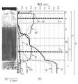
도 1은 본 실시형태의 절삭공구의 표면을 포함하는 단면에 대해서, (a) 주사형 전자현미경(SEM) 사진, (b) 글로우 방전 발광 분광 분석(GDS 분석) 데이터를 늘어 놓은 것이다.
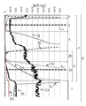
도 2는 도 1의 GDS 분석 데이터의 미량 성분의 분포 상태를 보기 위한 확대도이다.1 is a scanning electron microscope (SEM) photograph and (b) glow discharge emission spectroscopic analysis (GDS analysis) data for the section including the surface of the cutting tool according to the present embodiment.
Fig. 2 is an enlarged view for explaining distribution of trace components of GDS analysis data of Fig. 1; Fig.
도 1(a)는 절삭공구의 피복층을 포함하는 단면에 대한 주사형 전자현미경(SEM) 사진이며, 도 1(b)는 피복층의 표면으로부터 깊이 방향에 대한 글로우 방전 발광 분광 분석(GDS 분석) 데이터를 나타낸다. 또한, 도 2는 도 1에 있어서의 GDS 분석 데이터의 미량 성분의 분포 상태를 보기 위한 부분 확대도이다. 도 1, 도 2에는 각 원소의 분포 및 전자현미경 사진(SEM)과의 대응에 의해서 결정되는 각 층의 구성을 특정하고 있다.1 (a) is a scanning electron microscope (SEM) photograph of a cross section including a coating layer of a cutting tool, and Fig. 1 (b) is a graph showing a glow discharge emission spectral analysis . 2 is a partial enlarged view for showing the distribution of trace components of the GDS analysis data in Fig. Figs. 1 and 2 specify the composition of each layer determined by the distribution of each element and correspondence with the electron micrograph (SEM).
1이 기체(초경합금), 2가 Ti(Cx1Ny1Oz1)(0≤x1≤1, 0≤y1≤1, 0≤z1≤1, x1+y1+z1=1)로 이루어지는 Ti계층, 2a가 Ti(Cx11Ny11Oz11)(0≤x11≤1, 0≤y11≤1, 0≤z11≤1, x11+y11+z11=1)로 이루어지는 제 1 Ti계층, 2b가 Ti(Cx12Ny12Oz12)(0≤x12≤1, 0≤y12≤1, 0≤z12≤1, x12+y12+z12=1)로 이루어지는 제 2 Ti계층, 4가 (Ti, Al)(Cx2Ny2Oz2)(0≤x2≤1, 0≤y2≤1, 0≤z2≤1, x2+y2+z2=1)로 이루어지는 중간층, 5가 Al2O3층, 6이 Ti(Cx3Ny3Oz3)(0≤x3≤1, 0≤y3≤1, 0≤z3≤1, x3+y3+z3=1)로 이루어지는 최표층, 7이 각 층을 적층해서 이루어지는 피복층, 8이 절삭공구이며, 도 1에서는 절삭공구(8)의 일부를 나타내고 있다.A Ti layer composed of 1 gas (cemented carbide), divalent Ti (C x1 N y1 O z1 ) (0? X1? 1, 0? Y1? 1, 0? Z1 ? 1, x1 + y1 + z1 = 1) 2a the Ti (C N x11 y11 z11 O) (0≤x11≤1, 0≤y11≤1, 0≤z11≤1, x11 + y11 + z11 = 1) of claim 1 made of a Ti layer, 2b the Ti (C x12 N y12 O z12) (0≤x12≤1 , 0≤y12≤1, 0≤z12≤1, x12 + y12 + Ti layer of
또한, 중간층(4)은 생략할 수 있다. 본 실시형태에 의하면 기체(1)측의 제 1 Ti계층(2a)이 TiCN층, 제 2 Ti계층(2b)도 CN비가 다른 TiCN층이다.The intermediate layer 4 may be omitted. According to this embodiment, the
여기에서, GDS 분석에서 각 층의 두께를 산출할 수는 있지만, 각 층의 에칭 속도가 다르면 각 층의 두께의 오차가 커져버린다. 그래서, 주사형 전자현미경(SEM) 사진 및 전자선 마이크로 분석(EPMA) 데이터(도시하지 않음)와 대조하면서 각 층의 구성을 확인하면서, GDS 분석 데이터의 피크의 형태를 확인하여 각 층의 범위를 확정했다. 또한, 도 1(a)의 SEM 사진으로부터 알 수 있는 바와 같이, SEM 사진에 있어서의 각 층의 두께와 GDS 분석에서 검출되는 각 층의 두께는 비례하지 않는 부분이 있다. 또한, 도 1(a)의 SEM 사진에 있어서 피복층(7) 중에서 가장 층두께가 두꺼운 것이 Ti계층(2) 중 제 1 Ti계층(2a)인 TiCN층, 다음에 층두께가 두꺼운 것이 Al2O3층(5)인 것을 확인할 수 있고, 도 1(b)의 GDS 분석 데이터의 피크의 형태로부터 Ti의 분포가 높은 농도에서 추이하는 영역과 Al의 분포가 높은 농도에서 추이하는 영역이 존재하는 것을 확인할 수 있었다. 그리고, 이 Ti의 분포가 높은 농도에서 추이하는 영역을 제 1 Ti계층(2a)의 영역, 및 제 2 Ti계층(2b)의 영역, Al의 분포가 높은 농도에서 추이하는 영역을 Al2O3층(5)의 영역으로 특정한다. 그리고, 각 층의 두께의 중앙의 위치를 제 1 Ti계층(2a)의 중앙(LTi), Al2O3층(5)의 중앙(LAl)으로서 특정한다. 중간층(4) 및 최표층(6)에 대해서는 제 1 Ti계층(2a)과 제 2 Ti계층(2b)의 Ti계층(2)의 영역 및 Al2O3층(5)의 영역의 특정에 의해 결정되고, 중간층(4) 및 최표층(6)의 중앙의 위치에 대해서는 영역 중의 중앙의 위치를 중앙 위치(도시하지 않음)로서 특정한다.Here, although the thickness of each layer can be calculated in the GDS analysis, if the etching rates of the respective layers are different, the thickness error of each layer becomes large. Therefore, the shape of the peaks of the GDS analysis data is confirmed while confirming the constitution of each layer, in contrast with the scanning electron microscope (SEM) photograph and the electron beam microanalysis (EPMA) data (not shown) did. Also, as can be seen from the SEM photograph of FIG. 1 (a), there is a portion where the thickness of each layer in the SEM photograph is not proportional to the thickness of each layer detected in the GDS analysis. 1 (a), the thickest layer of the coating layer 7 is a TiCN layer which is the
여기에서, 각 층의 경계는 각 원소의 함유량이 급격하게 변화되는 굴곡점으로 한다. 그러나, 각 원소의 함유량이 급격하게 변화되는 위치가 명확하게 결정할 수 없는 경계에 있어서는 하기 방법으로 각 층의 경계를 특정한다. 즉, 제 1 Ti계층(2a)의 영역과 제 2 Ti계층(2b)의 영역의 경계는, 제 1 Ti계층(2a)의 영역에 있어서의 Ti의 함유량의 최고값에 대하여 Ti의 함유량이 10% 낮은 함유량으로 되는 위치로 정의한다. 마찬가지로, 제 2 Ti계층(2b)의 영역과 중간층(4)의 영역의 경계는, 제 2 Ti계층(2b)의 영역에 있어서의 Ti의 함유량의 최고값에 대하여 Ti의 함유량이 10% 낮은 함유량으로 되는 위치로 정의한다. 또한, 중간층(4)의 영역과 Al2O3층(5)의 영역의 경계는, Al2O3층(5)에 있어서의 Al의 함유량의 최고값에 대하여 Al의 함유량이 10% 낮은 함유량으로 되는 위치로 정의한다.Here, the boundary of each layer is a bending point at which the content of each element is abruptly changed. However, in a boundary where the content of each element is abruptly changed can not be clearly determined, the boundaries of each layer are specified by the following method. That is, the boundary between the
또한, GDS 분석에서는 피복층의 면내방향의 측정 영역이 1㎜ 정도로 넓기 때문에, 각 층의 층간에 요철이 있을 경우에는 각 층에 인접하는 다른 층의 성분이 혼재해서 검출될 경우가 있다. 또한, 각 층의 에칭 속도의 차이에 의해 GDS 분석에 있어서 제 1 Ti계층(2a)으로 특정된 영역 내의 기체측에는 기체(1)에 함유되는 성분이 혼재하고 있다. 또한, 중간층(4)으로 특정된 영역 내의 기체측에는 하층의 Ti계층(2)에 함유되는 성분이 혼재하고, 중간층(4)으로 특정된 영역 내의 표면측에는 상층의 Al2O3층(5)에 함유되는 성분이 혼재한 상태에서 검출되고 있다. 그 결과, GDS 분석에 있어서의 중간층(4)의 영역은 SEM 사진에서 관찰되는 실제의 두께보다 넓게 관찰되고 있다.Further, in the GDS analysis, since the measurement region in the in-plane direction of the coating layer is as wide as 1 mm, when there is unevenness between the layers, the components of other layers adjacent to each layer may be mixed and detected. In addition, due to the difference in the etching rates of the respective layers, components contained in the gas 1 are mixed in the gas side in the region specified by the
여기에서, 기체(1)의 적합예는 WC상, 결합상, 및 소망에 따라 B1형 고용상으로 형성되어 있다. 그리고, WC를 80∼94질량%, Co를 5∼15질량%, Cr을 Cr3C2 환산량으로 0.1∼1질량%, Cr을 제외한 주기표 제 4, 5 및 6족 금속의 군에서 선택되는 적어도 1종의 탄화물(WC를 제외함), 질화물 및 탄질화물 중 적어도 1종을 0∼10질량%의 비율로 함유한다.Here, the examples of the suitability of the base 1 are formed in the WC phase, the bonded phase, and the B1 type solid phase as desired. The WC is selected from the group consisting of 80 to 94 mass% of Co, 5 to 15 mass% of Co, 0.1 to 1 mass% of Cr in terms of Cr 3 C 2 , (Excluding WC), nitrides and carbonitrides in a proportion of 0 to 10% by mass.
본 실시형태에 의하면, 기체(1)의 표면에는 Ti계층(2), 중간층(4), Al2O3층(5) 및 최표층(6)이 기체(1)측으로부터 순차적으로 적층된 피복층(7)을 갖고 있다. 도 2의 글로우 방전 발광 분광 분석(GDS 분석)에 있어서, Ti계층(2) 중의 기체(1)측의 제 1 Ti계층(2a)의 두께의 중앙의 위치에 함유되는 Cr의 함유량이 기체(1)에 함유되는 Cr의 함유량보다 낮고, 또한 Al2O3층(5)의 두께의 중앙의 위치에 함유되는 Cr의 함유량보다 높다. 또한, 최표층(6)의 두께의 중앙의 위치에 함유되는 Cr의 함유량이 상기 Al2O3층의 두께의 중앙의 위치에 함유되는 Cr의 함유량보다 높다.According to the present embodiment, a
이것에 의해서, Ti가 함유되는 제 1 Ti계층(2a) 및 최표층(6), 또한 경우에 따라서는 제 2 Ti계층(2b)의 내산화성이 향상한다. 그 결과, 고속 절삭 등의 절삭날이 고온으로 되는 가공에서 있어서도 피복층(7)이 산화해서 경도가 저하하는 것을 억제하여 절삭공구(8)의 내마모성을 높일 수 있다. 또한, Al2O3층(5)에 있어서는 Cr의 함유량이 다른 층에 비해서 낮음으로써 내마모성이 향상한다고 하는 효과가 있다. 또한, 최표층(6)에 있어서는 Cr을 함유함으로써 피복층(7)의 표면에 있어서의 내용착성을 높이는 효과도 있다.This improves the oxidation resistance of the
즉, 제 1 Ti계층(2a)의 두께의 중앙의 위치에 함유되는 Cr의 함유량이 Al2O3층(5)의 두께의 중앙의 위치에 함유되는 Cr의 함유량과 같거나 또는 적으면, 피복층(7)의 산화가 진행하기 쉬운 경향이 있다. Al2O3층(5)의 두께의 중앙의 위치에 함유되는 Cr의 함유량이 제 1 Ti계층(2a)의 두께의 중앙의 위치에 함유되는 Cr의 함유량, 또는 최표층(6)의 두께의 중앙의 위치에 함유되는 Cr의 함유량과 같거나 또는 많으면, Al2O3층(5)의 내마모성이 저하하는 경향이 있다. 최표층(6)의 두께의 중앙의 위치에 함유되는 Cr의 함유량이 Al2O3층(5)의 두께의 중앙의 위치에 함유되는 Cr의 함유량과 같거나 또는 낮으면, 피복층(7)의 내용착성이 저하하는 경향이 있다.That is, when the content of Cr contained in the central position of the thickness of the
본 실시형태에서는 또한, 기체(1)에 함유되는 Cr의 함유량에 대한 제 1 Ti계층(2a), Al2O3층(5) 및 최표층(6)의 각 층의 두께의 중앙의 위치에 함유되는 Cr의 함유량의 비율을, 각각 CrTi, CrAl 및 Crs라고 했을 때, 0.5≤CrTi≤0.9, 0.01≤CrAl≤0.2, 0.4≤Crs≤0.7이다. 여기에서, 기체(1)에 함유되는 Cr의 함유량은 GDS 분석 데이터에 있어서 W 및 C의 함유량의 변화율이 5% 이내인 영역에 있어서 측정한다.In the present embodiment, the position of the center of the thickness of each layer of the
이것에 의해서, Ti가 함유되는 제 1 Ti계층(2a), 제 2 Ti계층(2b), 또한 최표층(6)의 내산화성이 향상되고, 고속 절삭 등의 절삭날이 고온으로 되는 가공에 있어서도 피복층(7)이 산화해서 경도가 저하하는 것을 억제하여 절삭공구(8)의 내마모성을 높일 수 있다. 또한, 중간층(4)을 생략한 피복층에 있어서도 동일한 효과를 얻을 수 있다.As a result, the oxidation resistance of the
또한, 본 실시형태에서는 기체(1)에 함유되는 Cr의 함유량에 대한 중간층(4)의 두께의 중앙의 위치에 함유되는 Cr의 함유량의 비율을 Crm이라고 했을 때, 0.2≤Crm≤0.5이다. 이것에 의해, 중간층(4)의 내산화성이 향상된다.Further, in the present embodiment is, 0.2≤Cr m ≤0.5 when said ratio of the content of Cr contained in the position of the center of the thickness of the intermediate layer 4 to the content of Cr contained in the base (1) Cr m . As a result, the oxidation resistance of the intermediate layer 4 is improved.
여기에서, 피복층(7) 중에는 Cr 이외에 W 및 Co가 함유되어 있다. 본 실시형태에 있어서는 기체(1)에 함유되는 W 및 Co의 함유량에 대한 제 1 Ti계층(2a), Al2O3층(5) 및 최표층(6)의 각 층에 함유되는 W 및 Co의 함유량의 비율을, 각각 WTi, WAl, Ws, CoTi, CoAl 및 Cos라고 했을 때, 0.05≤WTi≤0.3, WAl≤0.01, Ws≤0.01, 0.05≤CoTi≤0.3, CoAl≤0.01, Cos≤0.01이다. 즉, 기체(1)로부터 확산하는 W 및 Co는 Ti계층(2) 중으로 확산하여 기체(1)와 피복층(7)의 밀착성을 더욱 높일 수 있다. 그러나, W 및 Co는 고온으로 되면 산화하기 쉬우므로, Al2O3층(5) 및 최표층(6)에는 거의 확산하지 않아 피복층(7)의 산화를 억제할 수 있다.Here, in the coating layer 7, W and Co are contained in addition to Cr. In this embodiment, W and Co contained in each layer of the
이 때, 기체(1)에 함유되는 W 및 Co의 함유량에 대한 중간층(4)에 함유되는 W 및 Co의 함유량의 비율을, 각각 Wm 및 Com이라고 했을 때, Wm≤0.05, Com≤0.05이다. 즉, 기체(1)로부터 확산하는 W 및 Co는 중간층(4)에는 거의 확산하지 않아 피복층(7)의 산화를 억제할 수 있다.When the ratio of the content of W and the content of Co contained in the intermediate layer 4 to the content of W and Co contained in the base 1 is W m and Co m respectively, W m ≤0.05 and Co m ≪ / RTI > That is, W and Co diffused from the base 1 hardly diffuse into the intermediate layer 4, and oxidation of the coating layer 7 can be suppressed.
또한, 본 실시형태에 의하면, 기체(1) 중에는 불가피 불순물 성분으로서 Si 및 Fe가 함유되어 있고, 이것들이 피복층(7) 중에 확산되어 있다. 기체(1)에 함유되는 Si 및 Fe의 함유량에 대한 제 1 Ti계층(2a), Al2O3층(5) 및 최표층(6)의 각 층에 함유되는 Si 및 Fe의 함유량의 비율을, 각각 SiTi, SiAl 및 Sis, FeTi, FeAl 및 Fes라고 했을 때, 0.05≤SiTi≤0.4, SiAl≤0.01, Sis≤0.01, 0.05≤FeTi≤0.4, FeAl≤0.01, Fes≤0.01이다. 즉, 기체(1)로부터 확산하는 Si 및 Fe는 Ti계층(2) 중으로 확산하여 기체(1)와 피복층(7)의 밀착성을 더욱 향상시킬 수 있다. 그러나, Si 및 Fe는 고온으로 되면 산화하기 쉬우므로, Al2O3층(5) 및 최표층(6)에는 거의 확산하지 않아 피복층(7)의 산화를 억제할 수 있다.Further, according to the present embodiment, Si and Fe are contained as inevitable impurity components in the base body 1, and these are diffused into the coating layer 7. [ The ratio of the content of Si and Fe contained in each layer of the
이 때, 본 실시형태에 의하면, 기체(1)에 함유되는 Si 및 Fe의 함유량에 대한 중간층(4)에 함유되는 Si 및 Fe의 함유량의 비율을, 각각 Sim 및 Fem이라고 했을 때, Sim≤0.05, Fem≤0.05이다. 즉, 기체(1)로부터 확산하는 Si 및 Fe는 중간층(4)에는 거의 확산하지 않아 피복층(7)의 산화를 억제할 수 있다.At this time, according to the present embodiment, when the ratio of the content of Si and Fe contained in the intermediate layer 4 to the content of Si and Fe contained in the base body 1 is Si m and Fe m , respectively, Si m? 0.05, and Fe m? 0.05. That is, Si and Fe diffused from the base 1 hardly diffuse into the intermediate layer 4, and oxidation of the coating layer 7 can be suppressed.
또한, 본 실시형태에 의하면 기체(1) 및 피복층(7) 중에는 C(탄소)가 함유되어 있다. 기체(1)에 함유되는 C의 함유량에 대한 제 1 Ti계층(2a), 중간층(4), Al2O3층(5) 및 최표층(6)의 각 층에 함유되는 C의 함유량의 비율을, 각각 CTi, Cm, CAl 및 Cs라고 했을 때, 0.2≤CTi≤0.7, 0.01≤Cm≤0.18, CAl≤0.01, Cs≤0.30이다. 피복층(7) 중의 C 함유량을 제어함으로써 기체(1)와 피복층(7)의 밀착성을 더욱 높일 수 있다. CTi의 더욱 바람직한 범위는 0.3≤CTi≤0.6이다.According to the present embodiment, C (carbon) is contained in the substrate 1 and the coating layer 7. The ratio of the content of C contained in each layer of the
또한, 본 실시형태에 있어서의 Ti계층(2)은 기체(1)측의 제 1 Ti계층(2a), 제 2 Ti계층(2b) 모두 TiCN층이며, 이들 복수층을 적층한 것이었지만, Ti계층은 단층이라도 되고, 또는 3층 이상의 다층이라도 된다. 이 구성에 의해, Cr, W, Co, Fe, Si 및 C의 각 성분의 피복층(7)으로의 확산의 정도를 용이하게 조정할 수 있다.The
(제조 방법)(Manufacturing method)
상술한 본 실시형태의 절삭공구를 구성하는 초경합금의 제조 방법의 일례에 대하여 설명한다. 우선, WC 분말을 80∼94질량%와, 금속 Co 분말을 5∼15질량%와, Cr3C2 분말을 0.1∼1질량%, 소망에 따라 다른 금속 성분을 함유하는 화합물 분말을 0∼10질량% 이하의 비율로 조합한다.An example of a method of manufacturing a cemented carbide constituting the cutting tool of the present embodiment described above will be described. First, the WC powder is blended in an amount of 80 to 94 mass%, the metal Co powder in an amount of 5 to 15 mass%, the Cr 3 C 2 powder in an amount of 0.1 to 1 mass%, and the compound powder containing other metal components, By mass or less.
이 조합한 분말에 용매를 첨가해서 소정 시간 혼합·분쇄해서 슬러리로 한다. 이 슬러리에 바인더를 첨가해서 더 혼합하고, 스프레이 드라이어 등을 이용하여 슬러리를 건조하면서 혼합 분말의 조립(造粒)을 행한다. 이어서, 조립된 과립 을 이용하여 프레스 성형에 의해 절삭공구 형상으로 성형을 행한다. 또한, 소성로에서 탈지를 행한 후, 20∼2000Pa의 감압 분위기 중, 소성로의 온도를 1380∼1480℃의 소성 온도로 높여서 1∼1.5시간 소성해서 초경합금을 제작할 수 있다.A solvent is added to the combined powder and mixed and pulverized for a predetermined time to obtain a slurry. A binder is further added to the slurry and further mixed, and the slurry is dried using a spray dryer or the like to granulate the mixed powder. Subsequently, molding is performed in the shape of a cutting tool by press molding using the granulated granules. Further, after the degreasing is performed in the firing furnace, the cemented carbide can be manufactured by firing the firing furnace at a firing temperature of 1380 to 1480 캜 for 1 to 1.5 hours in a reduced pressure atmosphere of 20 to 2000 Pa.
그리고, 제작된 초경합금에 대해서 소망에 따라서 초경합금의 표면을 연마 가공하거나, 절삭날부에 호닝 가공을 실시하거나 한다. 그 후에 초경합금으로 이루어지는 기체를 산 처리나 알칼리 처리하여 기체의 표면 오염을 제거하고, Cr3C2 분말 또는 금속 크롬(Cr)을 함유하는 용액을 준비해 두고, 스프레이법, 함침법, 도포법에 의해 기체의 표면에 Cr 성분을 부착시켜 Cr 농도를 높여 둔다.Then, the surface of the cemented carbide is polished to the prepared cemented carbide as desired, or the cutting edge is honed. Thereafter, the surface of the base body made of cemented carbide is subjected to an acid treatment or an alkali treatment to remove surface contamination, and a solution containing Cr 3 C 2 powder or metal chrome (Cr) is prepared and sprayed, impregnated or coated A Cr component is attached to the surface of the gas to increase the Cr concentration.
이어서, 얻어진 기체의 표면에 화학 기상 증착(CVD)법에 의해 피복층(2)을 형성한다. 그 성막 조건의 일례에 대해서 설명하면, 우선 소망에 따라 기체의 표면에 제 1 Ti계층인 TiN(질화티타늄)층을 형성한다. 그 바람직한 성막 조건은, 혼합 가스 조성으로서 사염화티타늄(TiCl4) 가스를 0.5∼10체적%, 질소(N2) 가스를 10∼60체적%의 비율로 포함하고, 나머지가 수소(H2) 가스로 이루어지는 혼합 가스를 사용하고, 성막 온도를 800∼940℃, 압력을 8∼50kPa이다.Subsequently, a
이어서, TiN층의 상층에 제 2 Ti계층인 TiCN층을 형성한다. 그 성막 조건은 혼합 가스 조성으로서 사염화티타늄(TiCl4) 가스를 0.5∼10체적%, 질소(N2) 가스를 1∼60체적%, 아세토니트릴(CH3CN) 가스를 0.1∼3.0체적%의 비율로 포함하고, 나머지가 수소(H2) 가스로 이루어지는 혼합 가스를 사용하고, 성막 온도를 780∼850℃, 압력을 5∼25kPa의 조건을 들 수 있고, 이 조건에 의해 소위 주상결정으로 구성되는 MT(Moderate Temprature)-TiCN층이 성막된다. 아세토니트릴(CH3CN) 가스의 유량을 성막 중에 증감시킴으로써 주상결정의 결정 폭을 조정할 수 있다. 이어서 MT-TiCN층의 상층에 소위 입상결정으로 이루어지는 HT(High Temprature)-TiCN층을 형성한다. 구체적으로는, 상기 TiCN층에 계속해서 사염화티타늄(TiCl4) 가스를 0.1∼3체적%, 질소(N2) 가스를 0∼15체적%, 메탄(CH4) 가스 또는 아세토니트릴(CH3CN) 가스를 0.1∼10체적%의 비율로 포함하고, 나머지가 수소(H2) 가스로 이루어지는 혼합 가스를 사용하고, 성막 온도를 900∼1020℃, 압력을 5∼40kPa로 하는 성막 조건으로 바꾸어서 HT-TiCN층을 성막한다.Then, a TiCN layer, which is a second Ti layer, is formed on the TiN layer. The film formation conditions 0.1 to 3.0 titanium tetrachloride (TiCl 4) 0.5~10% by volume of the gas, a nitrogen (N 2) gas of 1 to 60% by volume, acetonitrile (CH 3 CN) gas as a mixed gas composition in vol.% (H 2 ) gas, and the film forming temperature is 780 to 850 ° C. and the pressure is 5 to 25 kPa. Under these conditions, the film is formed of so-called columnar crystals The MT (Moderate Temprature) -TiCN layer is formed. The crystal width of the columnar crystals can be adjusted by increasing or decreasing the flow rate of acetonitrile (CH 3 CN) gas during film formation. Next, an HT (High Temprature) -TiCN layer composed of so-called granular crystals is formed on the MT-TiCN layer. Specifically, subsequent to the TiCN layer of titanium tetrachloride (TiCl 4) gas 0.1~3% by volume, nitrogen (
계속해서, 중간층을 성막한다. TiAlCNO층을 성막하는 구체적인 성막 조건의 일례로서는 사염화티타늄(TiCl4) 가스를 0.1∼3체적%, 질소(N2) 가스를 1∼15체적%, 메탄(CH4)가스 또는 아세토니트릴(CH3CN) 가스를 0.1∼10체적%, 일산화탄소(CO) 가스를 0.5∼3.0체적%, 삼염화알루미늄(AlCl3)을 0.5∼3.0체적%의 비율로 포함하고, 나머지가 수소(H2) 가스로 이루어지는 혼합 가스를 사용하고, 성막 온도를 900∼1020℃, 압력을 5∼40kPa이다.Subsequently, an intermediate layer is formed. Titanium tetrachloride as the specific example of film forming conditions for forming the TiAlCNO layers (TiCl 4) gas 0.1~3% by volume, nitrogen (N 2) 1~15% by volume of the gas, methane (CH 4) gas or acetonitrile (CH 3 CN) containing 0.5 to 3.0 volume%, carbon monoxide (CO), the% by volume, 0.5 to 3.0 aluminum trichloride gas (AlCl 3) 0.1~10% by volume of the gas at the rate and the other is made of a hydrogen (H 2) gas A mixed gas is used, the film forming temperature is 900 to 1020 占 폚, and the pressure is 5 to 40 kPa.
그 후, 계속해 α형 Al2O3층을 형성한다. 구체적인 성막 조건의 일례로서는, 삼염화알루미늄(AlCl3) 가스를 0.5∼5.0체적%, 염화수소(HCl) 가스를 0.5∼3.5체적%, 이산화탄소(CO2) 가스를 0.5∼5.0체적%, 황화수소(H2S) 가스를 0∼0.5체적%, 나머지가 수소(H2) 가스로 이루어지는 혼합 가스를 사용하고, 성막 온도를 930∼1010℃, 압력을 5∼10kPa로 한다.Thereafter, an? -Type Al 2 O 3 layer is formed successively. As an example of the specific film forming conditions, aluminum trichloride (AlCl 3) gas 0.5~5.0% by volume, of hydrogen chloride 0.5 to 3.5% by volume (HCl) gas, carbon dioxide (CO 2) 0.5~5.0% by volume of the gas, hydrogen sulfide (H 2 S) gas at 0 to 0.5% by volume, and the remainder is hydrogen (H 2 ) gas is used as a deposition gas at a temperature of 930 to 1010 ° C. and a pressure of 5 to 10 kPa.
이어서, 소망에 따라 Al2O3층의 표면에 최표층을 성막한다. 최표층으로서 TiN층을 성막할 경우의 성막 조건으로서는, 혼합 가스 조성으로서 사염화티타늄(TiCl4) 가스를 0.1∼10체적%, 염화크롬(CrCl2) 가스를 0.005∼0.025체적%, 질소(N2) 가스를 1∼60체적%의 비율로 포함하고, 나머지가 수소(H2) 가스로 이루어지는 혼합 가스를 사용하고, 성막 온도를 855∼1010℃, 압력을 10∼85kPa로 한다.Subsequently, the outermost layer is formed on the surface of the Al 2 O 3 layer as desired. As the film formation condition in case of forming the TiN layer as the outermost surface layer, titanium tetrachloride (TiCl 4) 0.1~10% by volume of the gas as a mixed gas composition, chromium chloride (CrCl 2) 0.005~0.025% by volume of the gas, a nitrogen (N 2 ) Gas at a ratio of 1 to 60% by volume and the remainder is a hydrogen (H 2 ) gas, and the film forming temperature is 855 to 1010 캜 and the pressure is 10 to 85 kPa.
그리고, 피복층을 성막 종료 후, 성막 챔버 내를 압력 350kPa∼850kPa, 온도 1000∼1200℃로 해서 30분∼120분 유지한 후, 챔버 내를 냉각함으로써 기체 표면에 존재하는 Cr 성분, 및 W, Co, Fe, Si 및 C 성분을 피복층측에 확산시켜서 Ti계층, 중간층, Al2O3층 내에 소정의 비율로 함유시킨다. 최표층에 대해서는, 상기 성막시에 Cr 성분을 함유하는 원료 가스를 흘려서 최표층 내에 Cr 성분을 함유시킨다.After the coating layer is formed, the inside of the film forming chamber is maintained at a pressure of 350 kPa to 850 kPa and a temperature of 1000 to 1200 캜 for 30 to 120 minutes, and then the inside of the chamber is cooled to remove Cr components and W and Co , Fe, Si and C components are diffused on the coating layer side to be contained in the Ti layer, the intermediate layer and the Al 2 O 3 layer at a predetermined ratio. As for the outermost surface layer, a raw material gas containing a Cr component is flown at the time of film formation to contain a Cr component in the outermost layer.
그 후, 소망에 따라 형성한 피복층 표면의 적어도 절삭날부를 연마 가공한다. 이 연마 가공에 의해 절삭날부가 평활하게 가공되고, 피삭재의 용착을 억제하여 더욱 내결손성이 우수한 공구가 된다.Thereafter, at least the cutting edge portion of the surface of the coating layer formed in accordance with the desire is polished. By this grinding, the cutting edge portion is smoothly processed, the welding of the workpiece is suppressed, and the tool is further excellent in the resistance to breakage.
실시예Example
평균 입경 5㎛의 WC 분말에 대하여 평균 입경 1.5㎛의 금속 Co 분말을 8질량%, 평균 입경 1.0㎛의 TiC 분말을 0.8질량%, 평균 입경 1.0㎛의 NbC 분말을 3.5질량%, 평균 입경 2.0㎛의 ZrC 분말을 0.3질량%, 평균 입경 2.0㎛의 Cr3C2 분말을 0.6질량%의 비율로, 원료의 총계가 100질량%가 되도록 조합, 첨가하고, 이것에 유기용제를 첨가해서 혼합·분쇄한 후, 보형제를 첨가해서 더 혼합하고, 만들어진 슬러리를 스프레이 드라이어에 투입해서 조립 분말을 제작했다. 이어서, 이 조립 분말을 이용하여 프레스 성형에 의해 절삭공구 형상(CNMG120408PS)으로 성형을 행하고, 소성로에서 450℃로 3시간 탈지를 행한 후, 1450℃, 1시간으로 소성해서 초경합금을 제작했다.8% by mass of metallic Co powder having an average particle diameter of 1.5 占 퐉, 0.8% by mass of TiC powder having an average particle diameter of 1.0 占 퐉, 3.5% by mass of NbC powder having an average particle diameter of 1.0 占 퐉 and an average particle diameter of 2.0 占 퐉 of the ZrC powder, 0.3% by mass, average particle diameter of Cr 3 C 2 powder having an 2.0㎛ at a ratio of 0.6 mass%, the amount of material combinations such that 100% by weight, was added, and mixed by adding an organic solvent thereto, pulverized After that, a boehave agent was added and further mixed, and the slurry thus prepared was put into a spray dryer to prepare a granulated powder. Subsequently, the granulated powder was molded into a cutting tool shape (CNMG120408PS) by press molding, degreased at 450 deg. C for 3 hours in a firing furnace, and then fired at 1450 deg. C for 1 hour to prepare a cemented carbide.
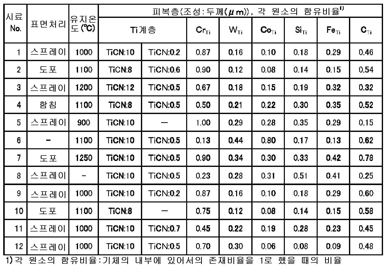
그리고, 상기 초경합금을 연삭 가공해서 CNMG120408PS의 대략 평판 형상으로 한 후, 이 기체의 표면에 대하여 절삭날부에 호닝 가공을 더 실시했다. 이어서, Cr3C2를 함유하는 슬러리를 이용하여 표 2의 방법으로 기체 표면의 Cr 농도를 높이는 처리를 행하는 표면 처리를 실시하여 기체의 표면에 있어서의 Cr의 함유량을 높였다.Then, the cemented carbide was subjected to grinding to obtain a substantially flat plate shape of CNMG120408PS, and further honing processing was performed on the cutting edge portion of the surface of the substrate. Subsequently, the slurry containing Cr 3 C 2 was subjected to a surface treatment to increase the Cr concentration on the surface of the substrate by the method of Table 2 to increase the Cr content on the surface of the substrate.
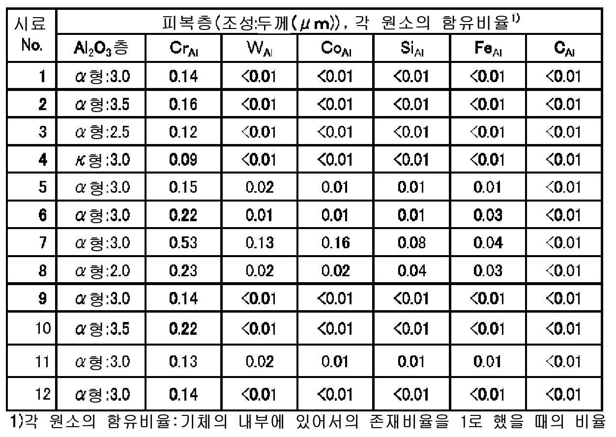
또한, 이 가공한 초경합금의 표면에 화학 기상 증착(CVD)법에 의해 표 1의 성막 조건으로 표 2∼표 5의 구성의 피복층을 순차적으로 성막했다. 또한, Ti계층은 제 1 Ti계층으로서 TiN층을 성막하고, 제 2 Ti계층은 MT-TiCN층과 HT-TiCN층의 적층으로 했다. 제 2 Ti계층의 두께는 HT-TiCN층의 두께를 0.5㎛로 일정하게 하고, MT-TiCN층의 두께를 조정하여 총두께가 표 2의 두께로 되도록 했다. 또한, 시료No.9에 대해서는, 최표층을 성막할 때의 혼합 가스 중에 염화크롬(CrCl4) 가스를 첨가하지 않고 성막하고, 시료No.12에 대해서는 최표층을 성막할 때의 혼합 가스 중에 염화크롬(CrCl4) 가스를 성막 시간의 중간 이후의 후반에만 첨가해서 성막했다. 성막 후, 챔버 내에 N2 가스를 500kPa가 되도록 충전으로 해서, 표 2에 나타내는 온도에서 60분 유지하는 성막 후 고온 유지 공정을 거쳐서 챔버 내를 냉각했다. 또한, 각 층의 두께는 피복층의 단면을 주사형 전자현미경으로 관찰해서 확인했다.Coating layers having the structures shown in Tables 2 to 5 were sequentially formed on the surface of the processed cemented carbide by the chemical vapor deposition (CVD) under the film forming conditions shown in Table 1. In addition, the Ti layer is formed of a TiN layer as a first Ti layer, and the second Ti layer is formed of a lamination of an MT-TiCN layer and an HT-TiCN layer. The thickness of the second Ti layer was set so that the thickness of the HT-TiCN layer was kept constant at 0.5 탆, and the thickness of the MT-TiCN layer was adjusted so that the total thickness became the thickness shown in Table 2. With respect to Sample No. 9, a film was formed without adding chromium chloride (CrCl 4 ) gas into the mixed gas at the time of forming the outermost layer, and in Sample No. 12, Chromium (CrCl 4 ) gas was added only in the latter half of the middle of the film forming time. After the film formation, the inside of the chamber was cooled through a high-temperature holding step after the film formation, in which N 2 gas was charged to 500 kPa in the chamber and maintained at the temperature shown in Table 2 for 60 minutes. The thickness of each layer was confirmed by observing the cross section of the coating layer with a scanning electron microscope.

얻어진 절삭공구에 대해서 표면으로부터 깊이 방향의 조성 변화에 대해서 GDS 분석(호리바 세이사쿠쇼사제 GD-PROFTLER, 분석 조건: 전력 20W, Ar 압력 600Pa, 방전 범위 2㎜φ, 샘플링 시간 0.3sec/point)을 행하고, 각 층의 중앙에 있어서의 Cr, W, Co, Fe, Si 및 C의 각 원소의 분포를 확인하고, 각 원소의 농도를 표 2∼표 5에 나타냈다. 또한, 절삭공구의 단면에 대해서 SEM 관찰을 행하였다.GD analysis (GD-PROFTLER manufactured by Horiba Seisakusho Co., Ltd., analysis conditions: electric power 20 W, Ar pressure 600 Pa,

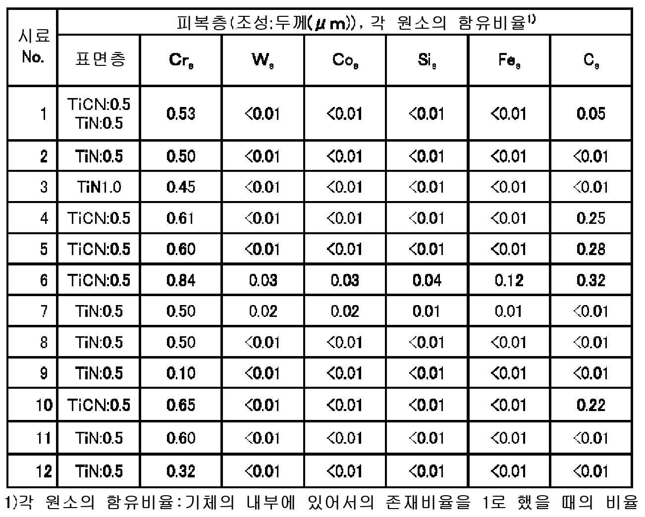
그리고, 이 공구를 이용하여 하기의 조건에 의해 연속 절삭 시험 및 강단속 절삭 시험을 행하고, 내마모성 및 내결손성을 평가했다.Using this tool, a continuous cutting test and a steel interrupted cutting test were conducted under the following conditions to evaluate abrasion resistance and scratch resistance.
(마모 평가 조건)(Wear evaluation condition)
피삭재 : SCM435Work material: SCM435
공구 형상 : CNMG120408PSTool shape: CNMG120408PS
절삭 속도 : 300m/분Cutting speed: 300 m / min
이송 속도 : 0.3㎜/revFeeding speed: 0.3 mm / rev
절개 : 2.0㎜(3초 절삭마다 절개 변동)Incision: 2.0 mm (incision variation per 3 second cutting)
절삭 시간 : 15분Cutting time: 15 minutes
절삭액 : 에멀젼 15% + 물 85% 혼합액Cutting fluid: 15% of emulsion + 85% of water mixture
평가 항목 : 현미경으로 절삭날을 관찰하여 플랭크 마모량·선단 마모량을 측정Evaluation item: Measurement of flank wear and tip wear by observing the cutting edge with a microscope
(강단속 절삭 조건)(Hard interrupted cutting condition)
피삭재 : SCM440 4개의 홈이 있는 것Workpiece: SCM440 With four grooves
공구 형상 : CNMG120408PSTool shape: CNMG120408PS
절삭 속도 : 300m/분Cutting speed: 300 m / min
이송 속도 : 0.35㎜/revFeeding speed: 0.35㎜ / rev
절개 : 1.5㎜Incision: 1.5 mm
절삭액 : 에멀젼 15% + 물 85% 혼합액Cutting fluid: 15% of emulsion + 85% of water mixture
평가 항목 : 결손에 이르는 충격횟수Evaluation item: Number of shocks leading to defects
충격횟수 1000회 시점에서 현미경으로 절삭날의 상태를 관찰 Observe the state of the cutting edge with a microscope at 1000 times of impact frequency
결과는 표 6에 나타냈다.The results are shown in Table 6.

표 1∼표 6에 나타내는 결과로부터, 기체의 표면에 TiN층을 형성하지 않은 시료No.5에서는, CrTi가 기체 중의 Cr 함유량과 같아져서 강단속 시험에 있어서 피복층이 박리되었다. 또한, 기체의 표면에 Cr을 부착시키지 않은 시료No.6, 및 성막 후의 열처리를 하지 않은 시료No.8에서는, CrTi가 CrAl에 대하여 동일하거나 또는 작아져 내마모성이 저하했다. 또한, 성막 후의 열처리 온도가 높고, Crs가 CrAl보다 작은 시료No.7에서는 피복층의 내마모성이 저하했다. 또한, 최표층 중의 Crs가 0.4보다 작은 시료No.9에서는 피복층에 용착이 발생하여 내마모성이 저하했다.From the results shown in Tables 1 to 6, in Sample No. 5 in which no TiN layer was formed on the surface of the base, the Cr Ti was equal to the Cr content in the base, and the coating layer was peeled off in the steel intermittent test. In the sample No. 6 in which Cr was not adhered to the surface of the base body and in the No. 8 sample in which the heat treatment was not performed after the film formation, Cr Ti became equal to or smaller than Cr Al and the abrasion resistance deteriorated. Further, in the sample No. 7 in which the heat treatment temperature after the film formation was high and Cr s was smaller than Cr Al , the wear resistance of the coating layer deteriorated. In Sample No. 9 in which Cr s in the outermost surface layer was smaller than 0.4, deposition was caused in the coating layer and the wear resistance was lowered.
이것에 대하여, TiN층, TiCN층, Al2O3층을 순차적으로 적층하고, GDS 분석에 있어서 CrTi가 기체의 Cr 함유량보다 작음과 아울러 CrAl이 보다 크고, CrAl이 Crs보다 작은 시료No.1∼4, 10∼12에서는, 어느 것이나 피복층의 밀착력이 높고, 또한 내마모성이 우수한 절삭 성능을 갖는 것이었다. 특히, 0.5≤CrTi≤0.9, 0.01≤CrAl≤ 0.2, 0.4≤Crs≤0.7을 충족시키는 시료No.1∼4에서는 내마모성이 특히 높은 것이었다.On the other hand, TiN layer, TiCN layer, Al 2 O laminating the three layers in sequence and, Cr Ti is less than the Cr content of the gas in the GDS analysis, as well as Cr Al is greater than, Cr Al is smaller samples than Cr s In Nos. 1 to 4 and 10 to 12, all of the coating layers had high adhesion and excellent abrasion resistance. Particularly, in the samples Nos. 1 to 4 satisfying 0.5? Cr Ti ? 0.9, 0.01? Cr Al ? 0.2 and 0.4? Cr s ? 0.7, abrasion resistance was particularly high.
1 : 기체(초경합금) 2 : Ti계층
2a : 제 1 Ti계층 2b : 제 2 Ti계층
4 : 중간층 5 : Al2O3층
6 : 최표층 7 : 피복층
8 : 절삭공구1: gas (cemented carbide) 2: Ti layer
2a:
4: intermediate layer 5: Al 2 O 3 layer
6: top layer 7: coating layer
8: Cutting tool
Claims (10)
글로우 방전 발광 분광 분석(GDS 분석)에 있어서 상기 기체에 함유되는 Cr의 함유량에 대한 상기 Ti계층 중의 기체측의 제 1 Ti계층, 상기 Al2O3층 및 상기 최표층의 각 층의 두께의 중앙의 위치에 함유되는 Cr의 함유량의 비율을, 각각 CrTi, CrAl 및 Crs라고 했을 때, 0.5≤CrTi ≤0.9, 0.01≤CrAl≤0.2, 0.4≤Crs≤0.7인 절삭공구.The method according to claim 1,
(GDS analysis) of the thickness of each layer of the first Ti layer, the Al 2 O 3 layer and the outermost surface layer on the gas side of the Ti layer with respect to the content of Cr contained in the gas in the glow discharge emission spectroscopic analysis the content ratio of Cr to be contained in a position, when each of said Cr Ti, Al and Cr Cr s, 0.5≤Cr ≤0.9 Ti, Al 0.01≤Cr ≤0.2, 0.4≤Cr s ≤0.7 the cutting tool.
글로우 방전 발광 분광 분석(GDS 분석)에 있어서 상기 기체에 함유되는 W 및 Co의 함유량에 대한 상기 제 1 Ti계층, 상기 Al2O3층 및 상기 최표층의 각 층에 함유되는 W 및 Co의 함유량의 비율을, 각각 WTi, WAl, Ws, CoTi, CoAl 및 Cos라고 했을 때, 0.05≤WTi≤0.3, WAl≤0.01, Ws≤0.01, 0.05≤CoTi≤0.3, CoAl≤0.01, Cos≤0.01인 절삭공구.3. The method of claim 2,
The content of W and Co contained in each of the layers of the first Ti layer, the Al 2 O 3 layer and the outermost layer with respect to the content of W and Co contained in the gas in the glow discharge emission spectroscopic analysis (GDS analysis) when the ratio of, respectively, when said Ti W, W Al, W s, Co Ti, Co and Al Co s, 0.05≤W ≤0.3 Ti, Al ≤0.01 W, W s ≤0.01, 0.05≤Co Ti ≤0.3, Co Al ≤ 0.01, Co s ≤ 0.01.
상기 기체 중에 Si 및 Fe가 함유되어 있고, 글로우 방전 발광 분광 분석(GDS 분석)에 있어서 상기 기체에 함유되는 Si 및 Fe의 함유량에 대한 상기 제 1 Ti계층, 상기 Al2O3층 및 상기 최표층의 각 층에 함유되는 Si 및 Fe의 함유량의 비율을, 각각 SiTi, SiAl 및 Sis, FeTi, FeAl 및 Fes라고 했을 때, 0.05≤SiTi≤0.4, SiAl≤0.01, Sis≤0.01, 0.05≤FeTi≤0.4, FeAl≤0.01, Fes≤0.01인 절삭공구.The method according to claim 2 or 3,
Wherein the gas contains Si and Fe, and the first Ti layer, the Al 2 O 3 layer, and the outermost layer when that content is the ratio of the Si and Fe to be contained in each layer, each Si Ti, Si and Al s Si, Ti Fe, Al and Fe Fe s, 0.05≤Si ≤0.4 Ti, Si ≤0.01 Al, Si s? 0.01, 0.05? Fe Ti? 0.4, Fe Al? 0.01, Fe s? 0.01.
글로우 방전 발광 분광 분석(GDS 분석)에 있어서 상기 기체에 함유되는 C의 함유량에 대한 상기 제 1 Ti계층, 상기 Al2O3층 및 상기 최표층의 각 층에 함유되는 C의 함유량의 비율을, 각각 CTi, CAl 및 Cs라고 했을 때, 0.2≤CTi≤0.7, CAl≤0.01, Cs≤0.30인 절삭공구.5. The method according to any one of claims 2 to 4,
The ratio of the content of C contained in each layer of the first Ti layer, the Al 2 O 3 layer and the outermost surface layer to the content of C contained in the gas in the glow discharge emission spectroscopic analysis (GDS analysis) C Ti , C Al, and C s , respectively, 0.2? C Ti? 0.7, C Al? 0.01, and C s ?
상기 Ti계층과 상기 Al2O3층 사이에 (Ti, Al)(Cx2Ny2Oz2)(0≤x2≤1, 0≤y2≤1, 0≤z2≤1, x2+y2+z2=1)로 이루어지는 중간층이 존재하는 절삭공구.6. The method according to any one of claims 1 to 5,
Between the Ti layer and the Al 2 O 3 layer (Ti, Al) (C x2 N y2 O z2) (0≤x2≤1, 0≤y2≤1, 0≤z2≤1, x2 + y2 + z2 = 1) is present.
글로우 방전 발광 분광 분석(GDS 분석)에 있어서 상기 기체에 함유되는 Cr의 함유량에 대한 상기 중간층의 두께의 중앙의 위치에 함유되는 Cr의 함유량의 비율을 Crm이라고 했을 때, 0.2≤Crm≤0.5인 절삭공구.The method according to claim 6,
When according to a glow discharge emission spectral analysis (GDS analysis) have a content ratio of Cr to be contained in the location of the center of the thickness of the intermediate layer for the content of Cr contained in the gas as Cr m, 0.2≤Cr m ≤0.5 Cutting tool.
글로우 방전 발광 분광 분석(GDS 분석)에 있어서 상기 기체에 함유되는 W 및 Co의 함유량에 대한 상기 중간층에 함유되는 W 및 Co의 함유량의 비율을, 각각 Wm 및 Com이라고 했을 때, Wm≤0.05, Com≤0.05인 절삭공구.8. The method according to claim 6 or 7,
When the content ratio of the W and Co contained in the intermediate layer for the content of W and Co contained in the gas in the glow discharge emission spectral analysis (GDS analysis), that each of W m and Co m, W m ≤ 0.05, Co m? 0.05.
글로우 방전 발광 분광 분석(GDS 분석)에 있어서 상기 기체에 함유되는 Si 및 Fe의 함유량에 대한 상기 중간층에 함유되는 Si 및 Fe의 함유량의 비율을, 각각 Sim 및 Fem이라고 했을 때, Sim≤0.05, Fem≤0.05인 절삭공구.9. The method according to any one of claims 6 to 8,
When according to a glow discharge emission spectral analysis (GDS analysis) have a content ratio of the Si and Fe to be contained in the intermediate layer for the content of Si and Fe contained in the gas, that each Si m and Fe m, Si m ≤ 0.05, and Fe m? 0.05.
상기 기체에 함유되는 C의 함유량에 대한 상기 중간층에 함유되는 C의 함유량의 비율을 Cm이라고 했을 때, 0.01≤Cm≤0.18인 절삭공구.10. The method according to any one of claims 6 to 9,
And a ratio of a content of C contained in the intermediate layer to a content of C contained in the gas is C m , 0.01? C m? 0.18.
Applications Claiming Priority (3)
| Application Number | Priority Date | Filing Date | Title |
|---|---|---|---|
| JP2013247849 | 2013-11-29 | ||
| JPJP-P-2013-247849 | 2013-11-29 | ||
| PCT/JP2014/081228 WO2015080149A1 (en) | 2013-11-29 | 2014-11-26 | Cutting tool |
Publications (2)
| Publication Number | Publication Date |
|---|---|
| KR20160077181A true KR20160077181A (en) | 2016-07-01 |
| KR101813536B1 KR101813536B1 (en) | 2017-12-29 |
Family
ID=53199088
Family Applications (1)
| Application Number | Title | Priority Date | Filing Date |
|---|---|---|---|
| KR1020167014151A Active KR101813536B1 (en) | 2013-11-29 | 2014-11-26 | Cutting tool |
Country Status (6)
| Country | Link |
|---|---|
| US (1) | US10113239B2 (en) |
| EP (1) | EP3075475A4 (en) |
| JP (1) | JP6276288B2 (en) |
| KR (1) | KR101813536B1 (en) |
| CN (1) | CN105792967B (en) |
| WO (1) | WO2015080149A1 (en) |
Families Citing this family (6)
| Publication number | Priority date | Publication date | Assignee | Title |
|---|---|---|---|---|
| JP6633736B2 (en) * | 2016-02-24 | 2020-01-22 | 京セラ株式会社 | Coated tool |
| KR102343013B1 (en) * | 2017-09-27 | 2021-12-24 | 교세라 가부시키가이샤 | Covered tool and cutting tool having same |
| KR102343014B1 (en) | 2017-09-27 | 2021-12-24 | 교세라 가부시키가이샤 | Covered tool and cutting tool having same |
| JP7243013B2 (en) * | 2019-03-28 | 2023-03-22 | 三菱マテリアル株式会社 | Surface-coated cutting tools with excellent fracture resistance |
| JP7431945B2 (en) * | 2020-03-27 | 2024-02-15 | 京セラ株式会社 | coated tools |
| CN116026810A (en) * | 2023-01-19 | 2023-04-28 | 青岛澳康质量检测技术有限公司 | A method and application for detecting copper content in antifouling paint based on radio frequency glow discharge spectrometer |
Citations (2)
| Publication number | Priority date | Publication date | Assignee | Title |
|---|---|---|---|---|
| JPH08118108A (en) | 1994-10-25 | 1996-05-14 | Mitsubishi Materials Corp | Surface coated tungsten carbide based cemented carbide cutting tool with excellent interlayer adhesion with hard coating layer |
| JP2011036988A (en) | 2009-08-06 | 2011-02-24 | Hitachi Tool Engineering Ltd | Coated cemented carbide tool |
Family Cites Families (15)
| Publication number | Priority date | Publication date | Assignee | Title |
|---|---|---|---|---|
| US5652045A (en) * | 1994-10-20 | 1997-07-29 | Mitsubishi Materials Corporation | Coated tungsten carbide-based cemented carbide blade member |
| JPH09262705A (en) * | 1996-03-28 | 1997-10-07 | Mitsubishi Materials Corp | Surface coated tungsten carbide based cemented carbide cutting tool with hard coating layer having excellent toughness |
| JP2000126905A (en) * | 1998-10-23 | 2000-05-09 | Mitsubishi Materials Corp | Surface-coated tungsten carbide-based cemented carbide cutting tool with excellent fracture resistance |
| US6251508B1 (en) * | 1998-12-09 | 2001-06-26 | Seco Tools Ab | Grade for cast iron |
| US6575671B1 (en) * | 2000-08-11 | 2003-06-10 | Kennametal Inc. | Chromium-containing cemented tungsten carbide body |
| US6554548B1 (en) * | 2000-08-11 | 2003-04-29 | Kennametal Inc. | Chromium-containing cemented carbide body having a surface zone of binder enrichment |
| US6589602B2 (en) * | 2001-04-17 | 2003-07-08 | Toshiba Tungaloy Co., Ltd. | Highly adhesive surface-coated cemented carbide and method for producing the same |
| US6733874B2 (en) * | 2001-08-31 | 2004-05-11 | Mitsubishi Materials Corporation | Surface-coated carbide alloy cutting tool |
| US7172807B2 (en) * | 2003-02-17 | 2007-02-06 | Kyocera Corporation | Surface-coated member |
| JP2005105397A (en) | 2003-10-02 | 2005-04-21 | Hitachi Tool Engineering Ltd | Coated cemented carbide |
| JP2005131730A (en) * | 2003-10-30 | 2005-05-26 | Mitsubishi Materials Corp | Surface coated cermet cutting tool with excellent chipping resistance with hard coating layer |
| SE528108C2 (en) * | 2004-07-13 | 2006-09-05 | Sandvik Intellectual Property | Coated cemented carbide inserts, especially for turning steel, and ways of manufacturing the same |
| US8182911B2 (en) * | 2006-03-28 | 2012-05-22 | Kyocera Corporation | Cutting tool, manufacturing method thereof and cutting method |
| JP5240668B2 (en) | 2009-03-10 | 2013-07-17 | 三菱マテリアル株式会社 | Surface-coated cutting tool with excellent chipping resistance in high-speed intermittent cutting of hard alloy steel |
| JP5419668B2 (en) * | 2009-12-14 | 2014-02-19 | 京セラ株式会社 | Surface covering member |
-
2014
- 2014-11-26 KR KR1020167014151A patent/KR101813536B1/en active Active
- 2014-11-26 EP EP14865641.6A patent/EP3075475A4/en not_active Withdrawn
- 2014-11-26 JP JP2015550959A patent/JP6276288B2/en active Active
- 2014-11-26 US US15/039,927 patent/US10113239B2/en active Active
- 2014-11-26 WO PCT/JP2014/081228 patent/WO2015080149A1/en not_active Ceased
- 2014-11-26 CN CN201480064946.2A patent/CN105792967B/en active Active
Patent Citations (2)
| Publication number | Priority date | Publication date | Assignee | Title |
|---|---|---|---|---|
| JPH08118108A (en) | 1994-10-25 | 1996-05-14 | Mitsubishi Materials Corp | Surface coated tungsten carbide based cemented carbide cutting tool with excellent interlayer adhesion with hard coating layer |
| JP2011036988A (en) | 2009-08-06 | 2011-02-24 | Hitachi Tool Engineering Ltd | Coated cemented carbide tool |
Also Published As
| Publication number | Publication date |
|---|---|
| EP3075475A1 (en) | 2016-10-05 |
| KR101813536B1 (en) | 2017-12-29 |
| EP3075475A4 (en) | 2017-06-21 |
| US20170009352A1 (en) | 2017-01-12 |
| US10113239B2 (en) | 2018-10-30 |
| JP6276288B2 (en) | 2018-02-07 |
| WO2015080149A1 (en) | 2015-06-04 |
| CN105792967A (en) | 2016-07-20 |
| CN105792967B (en) | 2017-11-10 |
| JPWO2015080149A1 (en) | 2017-03-16 |
Similar Documents
| Publication | Publication Date | Title |
|---|---|---|
| KR101813536B1 (en) | Cutting tool | |
| KR101841512B1 (en) | Cutting tool | |
| KR101700700B1 (en) | Cutting tool | |
| CN103108716B (en) | Surface-coated cutting tool | |
| CN104053815A (en) | Coated cutting tool and method of manufacturing the same | |
| KR20170057376A (en) | Surface-coated cutting tool in which hard coating layer exhibits excellent chipping resistance | |
| WO2014132512A1 (en) | Cutting tool | |
| US20120202032A1 (en) | Surface-coated cutting tool having hard-coating layer with excellent chipping resistance and fracturing resistance | |
| EP2959994B1 (en) | Surface-coated cutting tool and process for producing same | |
| CN109641286B (en) | Surface-coated cutting tools with a hard coating that exhibits excellent chipping resistance and peeling resistance | |
| WO2011052767A1 (en) | Surface coated cutting tool with excellent chip resistance | |
| KR20170086045A (en) | Surface-coated cutting tool | |
| JP2016083766A (en) | Surface coated cutting tool | |
| EP3511097A1 (en) | Cutting tool and method for producing same | |
| JP2017164859A (en) | Surface coated cutting tool with excellent chipping and peeling resistance with excellent hard coating layer | |
| JP4107433B2 (en) | α-type aluminum oxide coated member | |
| KR101894309B1 (en) | Coated tool | |
| JP5023779B2 (en) | Surface coated cutting tool with excellent chipping resistance due to hard coating layer | |
| JP2008264961A (en) | Surface coated cutting tool |
Legal Events
| Date | Code | Title | Description |
|---|---|---|---|
| A201 | Request for examination | ||
| P11-X000 | Amendment of application requested |
St.27 status event code: A-2-2-P10-P11-nap-X000 |
|
| P13-X000 | Application amended |
St.27 status event code: A-2-2-P10-P13-nap-X000 |
|
| PA0105 | International application |
St.27 status event code: A-0-1-A10-A15-nap-PA0105 |
|
| PA0201 | Request for examination |
St.27 status event code: A-1-2-D10-D11-exm-PA0201 |
|
| PG1501 | Laying open of application |
St.27 status event code: A-1-1-Q10-Q12-nap-PG1501 |
|
| D13-X000 | Search requested |
St.27 status event code: A-1-2-D10-D13-srh-X000 |
|
| D14-X000 | Search report completed |
St.27 status event code: A-1-2-D10-D14-srh-X000 |
|
| E902 | Notification of reason for refusal | ||
| PE0902 | Notice of grounds for rejection |
St.27 status event code: A-1-2-D10-D21-exm-PE0902 |
|
| P11-X000 | Amendment of application requested |
St.27 status event code: A-2-2-P10-P11-nap-X000 |
|
| P13-X000 | Application amended |
St.27 status event code: A-2-2-P10-P13-nap-X000 |
|
| E701 | Decision to grant or registration of patent right | ||
| PE0701 | Decision of registration |
St.27 status event code: A-1-2-D10-D22-exm-PE0701 |
|
| GRNT | Written decision to grant | ||
| PR0701 | Registration of establishment |
St.27 status event code: A-2-4-F10-F11-exm-PR0701 |
|
| PR1002 | Payment of registration fee |
St.27 status event code: A-2-2-U10-U12-oth-PR1002 Fee payment year number: 1 |
|
| PG1601 | Publication of registration |
St.27 status event code: A-4-4-Q10-Q13-nap-PG1601 |
|
| R18-X000 | Changes to party contact information recorded |
St.27 status event code: A-5-5-R10-R18-oth-X000 |
|
| PR1001 | Payment of annual fee |
St.27 status event code: A-4-4-U10-U11-oth-PR1001 Fee payment year number: 4 |
|
| PR1001 | Payment of annual fee |
St.27 status event code: A-4-4-U10-U11-oth-PR1001 Fee payment year number: 5 |
|
| PR1001 | Payment of annual fee |
St.27 status event code: A-4-4-U10-U11-oth-PR1001 Fee payment year number: 6 |
|
| PR1001 | Payment of annual fee |
St.27 status event code: A-4-4-U10-U11-oth-PR1001 Fee payment year number: 7 |
|
| PR1001 | Payment of annual fee |
St.27 status event code: A-4-4-U10-U11-oth-PR1001 Fee payment year number: 8 |
|
| PR1001 | Payment of annual fee |
St.27 status event code: A-4-4-U10-U11-oth-PR1001 Fee payment year number: 9 |
|
| U11 | Full renewal or maintenance fee paid |
Free format text: ST27 STATUS EVENT CODE: A-4-4-U10-U11-OTH-PR1001 (AS PROVIDED BY THE NATIONAL OFFICE) Year of fee payment: 9 |