EP3075504A1 - Dispositif de fabrication d'éléments de formage en béton dans une machine à mouler - Google Patents
Dispositif de fabrication d'éléments de formage en béton dans une machine à mouler Download PDFInfo
- Publication number
- EP3075504A1 EP3075504A1 EP16159447.8A EP16159447A EP3075504A1 EP 3075504 A1 EP3075504 A1 EP 3075504A1 EP 16159447 A EP16159447 A EP 16159447A EP 3075504 A1 EP3075504 A1 EP 3075504A1
- Authority
- EP
- European Patent Office
- Prior art keywords
- mold
- guide means
- mold part
- frame
- vertical direction
- Prior art date
- Legal status (The legal status is an assumption and is not a legal conclusion. Google has not performed a legal analysis and makes no representation as to the accuracy of the status listed.)
- Granted
Links
Images


Classifications
-
- B—PERFORMING OPERATIONS; TRANSPORTING
- B28—WORKING CEMENT, CLAY, OR STONE
- B28B—SHAPING CLAY OR OTHER CERAMIC COMPOSITIONS; SHAPING SLAG; SHAPING MIXTURES CONTAINING CEMENTITIOUS MATERIAL, e.g. PLASTER
- B28B7/00—Moulds; Cores; Mandrels
- B28B7/08—Moulds provided with means for tilting or inverting
-
- B—PERFORMING OPERATIONS; TRANSPORTING
- B28—WORKING CEMENT, CLAY, OR STONE
- B28B—SHAPING CLAY OR OTHER CERAMIC COMPOSITIONS; SHAPING SLAG; SHAPING MIXTURES CONTAINING CEMENTITIOUS MATERIAL, e.g. PLASTER
- B28B3/00—Producing shaped articles from the material by using presses; Presses specially adapted therefor
- B28B3/02—Producing shaped articles from the material by using presses; Presses specially adapted therefor wherein a ram exerts pressure on the material in a moulding space; Ram heads of special form
- B28B3/028—Centering the press head, e.g. using guiding pins or chamfered mould edges
-
- B—PERFORMING OPERATIONS; TRANSPORTING
- B28—WORKING CEMENT, CLAY, OR STONE
- B28B—SHAPING CLAY OR OTHER CERAMIC COMPOSITIONS; SHAPING SLAG; SHAPING MIXTURES CONTAINING CEMENTITIOUS MATERIAL, e.g. PLASTER
- B28B7/00—Moulds; Cores; Mandrels
- B28B7/0097—Press moulds; Press-mould and press-ram assemblies
-
- B—PERFORMING OPERATIONS; TRANSPORTING
- B28—WORKING CEMENT, CLAY, OR STONE
- B28B—SHAPING CLAY OR OTHER CERAMIC COMPOSITIONS; SHAPING SLAG; SHAPING MIXTURES CONTAINING CEMENTITIOUS MATERIAL, e.g. PLASTER
- B28B7/00—Moulds; Cores; Mandrels
- B28B7/24—Unitary mould structures with a plurality of moulding spaces, e.g. moulds divided into multiple moulding spaces by integratable partitions, mould part structures providing a number of moulding spaces in mutual co-operation
-
- B—PERFORMING OPERATIONS; TRANSPORTING
- B30—PRESSES
- B30B—PRESSES IN GENERAL
- B30B15/00—Details of, or accessories for, presses; Auxiliary measures in connection with pressing
- B30B15/04—Frames; Guides
- B30B15/041—Guides
Definitions
- the invention relates to an apparatus for producing concrete moldings in a molding machine.
- Devices for the production of concrete moldings such.
- paving stones are typically used for machining and contain a molding machine with a punch unit and a form of a molded mold base, in which the punch unit can intervene.
- the lower mold part usually one or more mold cavities are formed, which are open up and down.
- the mold base is placed with a lower boundary plane of a stone field on a horizontal surface, which closes the lower openings of the mold.
- the mold nests are filled with concrete amount, which is then pressed through arranged on the stamp unit printing plates in which the printing plates are sunk through the upper openings in the mold cavities. Connecting is done by shaking typically the pad a solidification of the concrete amount to form-stable concrete moldings. These are removed from the mold through the lower openings of the mold cavities.
- the stamp unit is connected to a typically hydraulically actuated vertical movement unit of the molding machine and by means of this vertically movable.
- the connection can be given in conventional construction via a Auflastü, which usually forms with the stamp unit a Formoberteil as uniformly manageable assembly.
- a uniform stone height is achieved even with different compression of the concrete amount.
- a stone mold for making concrete blocks comprising a mold top having at least one punch with a pressure piece and a mold bottom having at least one mold cavity for use in a stone forming machine, the mold bottom being movable up and down in a stone forming machine.
- the lower mold part can be deposited on a mold base of the stone molding machine and the upper mold part is detachable with an up and down movable machine mount the stone forming machine.
- a filling box of the stone forming machine can be moved over the lower mold part and the upper mold part and / or the lower mold part has play with a machine frame of the stone forming machine.
- a centering device is provided for aligning the lower mold part and the upper mold part in an xy plane.
- an exact centering of the two mold parts is effected to each other, wherein a conical section at the centering device after the immersion of the pressure piece in the mold cavity, the centering of the mold parts slowly free again.
- an apparatus for producing concrete moldings in a molding machine comprising a mold top with at least one plunger for transmitting a force to at least one pressure plate, wherein the pressure plate is insertable in a vertical direction in an opening of a mold cavity in a mold base, wherein the lower mold part is surrounded by a frame which has a guide means connected to the upper mold part, which is designed such that the lower mold part bears against the mold top can be tilted out of the vertical direction during the engagement of the printing plates in the openings of the mold cavity.
- the lower mold part is not connected to the upper mold part with a forced operation, which would allow only a determination of the relative positions between the upper mold part and lower mold part.
- a guide means which allows tilting of the upper mold from the vertical direction, higher stability and longer life of the pressure plate attached to the pressure plates allows, in particular fine structures such. B. depressions or phases on the printing plates, have less wear.
- the solution according to the invention thus does not attempt to place the correct and centric installation of the lower mold part relative to the upper mold part in the center to prevent contact of a pressure plate with an opening of the mold can, but by obtaining an additional degree of freedom in the movement of Pressure plates impact in case of touch to keep it low.
- the invention allows a kind of self-adjustment, so that can be achieved by the possibility of tilting and possibly twisting unprecedented downtime.
- the guide means is arranged on two opposite sides of the frame.
- the guide means into individual components, wherein it is considered sufficient to provide only two opposite sides of the frame with parts of the guide means.
- a part of the guide means can be arranged on the two shorter sides of the mold cavity opposite one another in the region of a corner of the mold cavity.
- the guide means comprises an elongated body formed along the vertical direction with side lines at least partially parallel to the vertical direction, which engages in an at least partially corresponding passage.
- the guide means can be easily formed by an elongated body, which is guided by a corresponding passage.
- the elongate body has an outer surface which is selected over the entire extent of the body parallel to an inner dimension of the passage.
- at least individual sections of the elongate body or parts of the passage to be designed as depressions with surfaces lying further inwards, so that they can not come into contact with the respective corresponding part.
- such embodiments are not excluded within the scope of the invention.
- the elongated body with the upper mold part and the passage are connected to the lower mold part.
- a particularly simple realization of the guide means is that the implementation is arranged in the lower mold part and the upper mold part is provided with the elongated body. Accordingly, the previously used in molding machines usually embodiment of a mold base can be used further, with only a corresponding implementation must be present.
- the elongated body and the passage have dimensions which are selected such that a maximum value of the tilting of the lower mold part against the upper mold part is predetermined.
- the lower mold part is tiltable against the upper mold part by an angle which is in the range of less than 2 ° and in particular is about 1 °.
- the elongated body is designed as a circular cylindrical pin which engages in a sleeve provided on the frame with a circular cylindrical inner surface provided as a bushing.
- the elongated body is designed as a circular cylindrical pin which engages in a corresponding socket.
- the pin may for example be made of its hardened steel, so that when tilting from lower part to upper part of the likewise hardened bushing allow a relative movement of mold base to upper mold, but low wear values occur, so that the device according to the invention not by material loading in the guide means with respect to their Life is limited.
- the outer diameter of the circular cylindrical pin is selected in dependence on a height of the bushing along the vertical direction and an inner diameter of the bush arranged in the frame.
- both outer diameter of the pin and the inner diameter of the frame must be used be considered, which must be considered as an additional parameter present in the axial direction of the pin height of the socket. Due to these dimensions, the possible tilt can thus be determined.
- the guide pin and / or the socket are exchangeably mounted in the guide means.
- the guide means on the frame of the mold base laterally outside the mold cavity and outside the plunger side of the upper mold shell can be screwed.
- the invention can also be extended to existing molding machines according to this embodiment, in which the components of the guide means are subsequently applied, for example, to the frame of the mold base and on the upper mold outside the plunger.
- a device VO is shown, which is suitable for the production of concrete moldings in a molding machine.
- the device VO has a replaceably arranged shape, which is formed by a lower mold part FU and a upper mold part FB.
- the mold base FU has a form nest on a conventional field, which has a correspondingly selected number of openings, so that concrete moldings can be produced in the desired number or size with the device VO.
- the upper mold part FB has a plurality of printing plates DP, wherein each printing plate DP corresponds to an opening in the lower mold part FU.
- the printing plates DP are each connected via a plunger DS with a stamp plate ST.
- a loading device AE which can compress via the plunger DS a introduced into the openings of the mold cavity in the lower mold part FU amount of concrete as filling material accordingly.
- the loading element AE has fastening elements on its upper side, which, together with further elements which are not the subject of the present invention, enable the loading element AE to be accommodated in a molding machine.
- the mold base is usually provided with a plurality of openings, wherein the mold cavity forming openings are surrounded by a frame RA.
- a guide means FM is arranged, which ensures an alignment of the mold base FU relative to the mold top FO.
- the guide FM can be divided into individual units, as in Fig. 1 shown, for example, are arranged on two opposite sides of the usually rectangular frame RA.
- the plane spanned by the pressure plates DP is referred to below as the xy plane.
- the xy plane In the vertical direction, ie along the plunger DS is the z-direction.
- the guide means FM is designed so that the lower mold part FU can tilt slightly against the upper mold part FB.
- tilting is understood to mean a deviation from the xy plane, so that when the printing plates DP are dipped into the mold cavities of the mold bottom part FU in the event of tilting, formerly parallel sections of the mold top part FB and of the mold bottom part FU have an angle to each other.
- the tilting can not only take place along the x-direction or the y-direction, since it is provided in particular that a tilting with respect to both directions should be possible.
- FIG. 2 A corresponding tilted arrangement of the device VO is in Fig. 2 shown. It can be seen that the stops AS, which normally cause a limitation of immersion of the printing plates DP into the mold cavities of the mold base FU when fully filled, do not simultaneously rest on the frame RA or on the mold bottom FU. It should be noted that the in Fig. 2 chosen representation is greatly exaggerated because the angle formed between the tilted and the parallel state moves in the range of about 1 °.
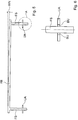
- the device VO is shown again in a side view. It can be seen that the guide means FM does not have to be arranged centrally on the frame RA of the lower mold part FU or of the upper mold part FB. Furthermore is Fig. 3 it can be seen that the guide means FM has a lower portion into which a cylindrical guide pin FS can dip. The lower portion is formed as a socket, wherein the guide pin FS within the socket, which has a cylindrical inner side, a certain amount of play.
- the guide pin FS is fastened to the upper mold part FB by means of a holder HA, wherein the lower portion of the guide means FM can be screwed onto the lower mold part FU. This procedure allows a simple retrofitting of existing devices VO.
- Fig. 4 is the side view off Fig. 3 shown again from the opposite side.
- the attachment of the guide means FM is chosen here identical to the opposite side, with other configurations are conceivable here.
- a fastening screw BF is shown, which holds the guide pin FS of the guide means FM. Accordingly, it is possible to replace, for example, after prolonged operation of the device VO a guide pin FS or more guide pins FS.
- Fig. 5 is shown in a schematic view again tilting of the mold base FU against the upper mold FB.
- the mold base which is in Fig. 5 is shown as a lower edition UA, as already mentioned, outside of the frame RA record the guide pins FS. Due to the selected dimensioning within the implementation of the lower edition UA thus tilting of the mold base FU is possible against the upper mold FB, which in Fig. 5 is shown schematically by the angle WN.
- the angle WN may be less than 2 °, in particular, a value of about 1 ° has been found to be advantageous. Since the limitation of the angle WN is advantageously achieved by the dimensioning of the guide pin FS in the implementation within the lower edition UA, this is in Fig. 5 marked as detail A, shown enlarged again.
- Fig. 6 the detail A is shown in a sectional view, wherein within the lower support UA a bush BU is indicated, which limits the circular cylindrical outer surface of the guide pin FS with their circular cylindrical inner surfaces.
- the inner diameter of the sleeve BU and the outer diameter of the guide pin FS can be calculated without difficulty with a known height of the sleeve BU and the distances between the two guide pins FS to each other. In order to achieve a tilt of less than 1 °, for example, at a distance of about 1.5 m of the two guide pins FS to each other, the guide pin can engage with an outer diameter of 40 mm in a 14 mm high socket BU.
- the inner diameter of the sleeve BU is selected to be about 10% larger than the outer diameter of the guide pin FS to achieve the desired tilt of less than 1 ° of the angle WN.
Landscapes
- Engineering & Computer Science (AREA)
- Mechanical Engineering (AREA)
- Manufacturing & Machinery (AREA)
- Chemical & Material Sciences (AREA)
- Ceramic Engineering (AREA)
- Press-Shaping Or Shaping Using Conveyers (AREA)
- Moulds, Cores, Or Mandrels (AREA)
- Moulds For Moulding Plastics Or The Like (AREA)
Priority Applications (1)
| Application Number | Priority Date | Filing Date | Title |
|---|---|---|---|
| PL16159447.8T PL3075504T5 (pl) | 2015-03-16 | 2016-03-09 | Urządzenie do wytwarzania kształtek betonowych w maszynie formierskiej |
Applications Claiming Priority (1)
| Application Number | Priority Date | Filing Date | Title |
|---|---|---|---|
| DE102015103829.3A DE102015103829A1 (de) | 2015-03-16 | 2015-03-16 | Vorrichtung zur Herstellung von Betonformteilen in einer Formmaschine |
Publications (3)
| Publication Number | Publication Date |
|---|---|
| EP3075504A1 true EP3075504A1 (fr) | 2016-10-05 |
| EP3075504B1 EP3075504B1 (fr) | 2022-01-05 |
| EP3075504B2 EP3075504B2 (fr) | 2026-01-07 |
Family
ID=55650079
Family Applications (1)
| Application Number | Title | Priority Date | Filing Date |
|---|---|---|---|
| EP16159447.8A Active EP3075504B2 (fr) | 2015-03-16 | 2016-03-09 | Dispositif de fabrication d'éléments de formage en béton dans une machine à mouler |
Country Status (9)
| Country | Link |
|---|---|
| US (1) | US9610708B2 (fr) |
| EP (1) | EP3075504B2 (fr) |
| CA (1) | CA2923914C (fr) |
| DE (1) | DE102015103829A1 (fr) |
| DK (1) | DK3075504T4 (fr) |
| ES (1) | ES2905475T3 (fr) |
| FI (1) | FI3075504T4 (fr) |
| HU (1) | HUE057943T2 (fr) |
| PL (1) | PL3075504T5 (fr) |
Families Citing this family (3)
| Publication number | Priority date | Publication date | Assignee | Title |
|---|---|---|---|---|
| CN106596238B (zh) * | 2016-10-19 | 2023-07-21 | 浙江科技学院(浙江中德科技促进中心) | 吻合岩石结构面上下盘的整体成型制作模具 |
| DE102019108574A1 (de) * | 2019-04-02 | 2020-10-08 | Kobra Formen Gmbh | Führungseinrichtung in einer Formmaschine und Formmaschine mit einer solchen Führungseinrichtung |
| DE102019135427A1 (de) * | 2019-12-20 | 2021-06-24 | Kobra Formen Gmbh | Vorrichtung zur Herstellung von Betonsteinen |
Citations (5)
| Publication number | Priority date | Publication date | Assignee | Title |
|---|---|---|---|---|
| DE3638207A1 (de) | 1986-11-08 | 1988-05-11 | Netter Gmbh | Verfahren zur herstellung von betonfomsteinen und vorrichtung zur durchfuehrung des verfahrens |
| DE19924926C1 (de) | 1999-05-31 | 2000-04-13 | Hubaleck Gmbh U Co Kg | Steinformmaschine mit Steinform für Mauerwerksteine |
| DE102004004188A1 (de) * | 2004-01-28 | 2005-10-06 | Manfred Lebherz | Beton-Formstein-Fertigungseinrichtung |
| DE102005048930A1 (de) | 2004-11-12 | 2006-05-18 | Rampf Formen Gmbh | Steinform, insbesondere zur Herstellung von Betonsteinen und Steinformmaschine mit Steinform |
| US20060197259A1 (en) * | 2005-03-01 | 2006-09-07 | Rampf Molds Industries, Inc. | Apparatus and method for a mold alignment system |
Family Cites Families (3)
| Publication number | Priority date | Publication date | Assignee | Title |
|---|---|---|---|---|
| US2479350A (en) * | 1947-10-03 | 1949-08-16 | Jr John C Haggart | Apparatus for molding reflector devices |
| US4941813A (en) * | 1988-12-13 | 1990-07-17 | Grubb Jr Lloyd T | Mold guidance system for block making machinery |
| DE102008017964A1 (de) † | 2008-04-08 | 2009-10-15 | Rampf Formen Gmbh | Anlage zur Herstellung von Formsteinen |
-
2015
- 2015-03-16 DE DE102015103829.3A patent/DE102015103829A1/de not_active Withdrawn
-
2016
- 2016-03-09 EP EP16159447.8A patent/EP3075504B2/fr active Active
- 2016-03-09 FI FIEP16159447.8T patent/FI3075504T4/fi active
- 2016-03-09 HU HUE16159447A patent/HUE057943T2/hu unknown
- 2016-03-09 ES ES16159447T patent/ES2905475T3/es active Active
- 2016-03-09 DK DK16159447.8T patent/DK3075504T4/da active
- 2016-03-09 PL PL16159447.8T patent/PL3075504T5/pl unknown
- 2016-03-15 US US15/070,209 patent/US9610708B2/en active Active
- 2016-03-16 CA CA2923914A patent/CA2923914C/fr active Active
Patent Citations (5)
| Publication number | Priority date | Publication date | Assignee | Title |
|---|---|---|---|---|
| DE3638207A1 (de) | 1986-11-08 | 1988-05-11 | Netter Gmbh | Verfahren zur herstellung von betonfomsteinen und vorrichtung zur durchfuehrung des verfahrens |
| DE19924926C1 (de) | 1999-05-31 | 2000-04-13 | Hubaleck Gmbh U Co Kg | Steinformmaschine mit Steinform für Mauerwerksteine |
| DE102004004188A1 (de) * | 2004-01-28 | 2005-10-06 | Manfred Lebherz | Beton-Formstein-Fertigungseinrichtung |
| DE102005048930A1 (de) | 2004-11-12 | 2006-05-18 | Rampf Formen Gmbh | Steinform, insbesondere zur Herstellung von Betonsteinen und Steinformmaschine mit Steinform |
| US20060197259A1 (en) * | 2005-03-01 | 2006-09-07 | Rampf Molds Industries, Inc. | Apparatus and method for a mold alignment system |
Also Published As
| Publication number | Publication date |
|---|---|
| US9610708B2 (en) | 2017-04-04 |
| DE102015103829A1 (de) | 2016-09-22 |
| EP3075504B2 (fr) | 2026-01-07 |
| FI3075504T4 (fi) | 2026-04-08 |
| ES2905475T3 (es) | 2022-04-08 |
| EP3075504B1 (fr) | 2022-01-05 |
| HUE057943T2 (hu) | 2022-06-28 |
| PL3075504T3 (pl) | 2022-03-21 |
| DK3075504T4 (da) | 2026-03-30 |
| CA2923914C (fr) | 2018-05-29 |
| DK3075504T3 (da) | 2022-02-07 |
| PL3075504T5 (pl) | 2026-04-20 |
| US20160271828A1 (en) | 2016-09-22 |
| CA2923914A1 (fr) | 2016-09-16 |
Similar Documents
| Publication | Publication Date | Title |
|---|---|---|
| EP4076881B1 (fr) | Dispositif pour la fabrication de blocs de béton | |
| EP3253567B1 (fr) | Presse à poudre présentant une infrastructure conique | |
| EP0730936B2 (fr) | Moule pour presse à vibrations | |
| DE102013209775B3 (de) | Speisereinsatz | |
| EP2982458B1 (fr) | Systeme a utiliser lors de la production d'un moule divisible | |
| WO2011127925A1 (fr) | Dispositif et procédé pour la fabrication de corps moulés en béton et moule à cet effet | |
| EP3075504B1 (fr) | Dispositif de fabrication d'éléments de formage en béton dans une machine à mouler | |
| EP3075505B1 (fr) | Dispositif de fabrication d'éléments de formage en béton | |
| DE60302471T2 (de) | Ausrichtungsmittel für eine spritzgiessvorrichtung | |
| DE102005044759B4 (de) | Vorrichtung zum Herstellen eines Formteils | |
| WO2019002600A1 (fr) | Plaque de niveau d'un outil de presse | |
| EP2718071A1 (fr) | Machine de moulage de blocs et procede pour regler en hauteur une machine de moulage de blocs | |
| DE102007019388A1 (de) | Form zur Herstellung von Betonformsteinen und Verfahren zu deren Herstellung | |
| DE202011108698U1 (de) | Vorrichtung zur Erzeugung einer abgießbaren Markierung an einem Kern oder an einer Gießform für den Abguss eines Gießteiles | |
| DE102017102323A1 (de) | Vorrichtung zur Herstellung von Betonformteilen | |
| DE102015206587A1 (de) | Verfahren zur Herstellung einer Baugruppe | |
| EP3718718B1 (fr) | Dispositif de guidage dans une machine de moulage et machine de moulage dotée d'un tel dispositif de guidage | |
| EP4292789A1 (fr) | Moule de coulée sous pression | |
| EP2718070B1 (fr) | Machine de moulage de blocs comportant un élément porteur à guidage linéaire | |
| DE4411350C2 (de) | Vorrichtung zur Herstellung eines Käfigs für Wälzlager | |
| WO2019048688A1 (fr) | Dispositif de fabrication de moules de béton | |
| DE102005058403A1 (de) | Vorrichtung zur Herstellung von Betonformsteinen und Formensystem | |
| DE202018104816U1 (de) | Formwechselsystem und Formungsmaschine | |
| DE102012022210A1 (de) | Verfahren zur Herstellung einer Vorrichtung mit mindestens einer Mikrobohrung und Vorrichtung | |
| EP3466637A1 (fr) | Plaque de serrage d'outil pour une machine de traitement de la matière plastique, en particulier pour une machine de moulage par injection |
Legal Events
| Date | Code | Title | Description |
|---|---|---|---|
| PUAI | Public reference made under article 153(3) epc to a published international application that has entered the european phase |
Free format text: ORIGINAL CODE: 0009012 |
|
| AK | Designated contracting states |
Kind code of ref document: A1 Designated state(s): AL AT BE BG CH CY CZ DE DK EE ES FI FR GB GR HR HU IE IS IT LI LT LU LV MC MK MT NL NO PL PT RO RS SE SI SK SM TR |
|
| AX | Request for extension of the european patent |
Extension state: BA ME |
|
| STAA | Information on the status of an ep patent application or granted ep patent |
Free format text: STATUS: REQUEST FOR EXAMINATION WAS MADE |
|
| 17P | Request for examination filed |
Effective date: 20170405 |
|
| RBV | Designated contracting states (corrected) |
Designated state(s): AL AT BE BG CH CY CZ DE DK EE ES FI FR GB GR HR HU IE IS IT LI LT LU LV MC MK MT NL NO PL PT RO RS SE SI SK SM TR |
|
| STAA | Information on the status of an ep patent application or granted ep patent |
Free format text: STATUS: EXAMINATION IS IN PROGRESS |
|
| 17Q | First examination report despatched |
Effective date: 20181023 |
|
| GRAP | Despatch of communication of intention to grant a patent |
Free format text: ORIGINAL CODE: EPIDOSNIGR1 |
|
| STAA | Information on the status of an ep patent application or granted ep patent |
Free format text: STATUS: GRANT OF PATENT IS INTENDED |
|
| INTG | Intention to grant announced |
Effective date: 20210916 |
|
| GRAS | Grant fee paid |
Free format text: ORIGINAL CODE: EPIDOSNIGR3 |
|
| GRAA | (expected) grant |
Free format text: ORIGINAL CODE: 0009210 |
|
| STAA | Information on the status of an ep patent application or granted ep patent |
Free format text: STATUS: THE PATENT HAS BEEN GRANTED |
|
| AK | Designated contracting states |
Kind code of ref document: B1 Designated state(s): AL AT BE BG CH CY CZ DE DK EE ES FI FR GB GR HR HU IE IS IT LI LT LU LV MC MK MT NL NO PL PT RO RS SE SI SK SM TR |
|
| REG | Reference to a national code |
Ref country code: GB Ref legal event code: FG4D Free format text: NOT ENGLISH |
|
| REG | Reference to a national code |
Ref country code: CH Ref legal event code: EP |
|
| REG | Reference to a national code |
Ref country code: AT Ref legal event code: REF Ref document number: 1460124 Country of ref document: AT Kind code of ref document: T Effective date: 20220115 |
|
| REG | Reference to a national code |
Ref country code: DE Ref legal event code: R096 Ref document number: 502016014336 Country of ref document: DE |
|
| REG | Reference to a national code |
Ref country code: FI Ref legal event code: FGE Ref country code: IE Ref legal event code: FG4D Free format text: LANGUAGE OF EP DOCUMENT: GERMAN |
|
| REG | Reference to a national code |
Ref country code: DK Ref legal event code: T3 Effective date: 20220131 |
|
| REG | Reference to a national code |
Ref country code: NL Ref legal event code: FP |
|
| REG | Reference to a national code |
Ref country code: SE Ref legal event code: TRGR |
|
| REG | Reference to a national code |
Ref country code: NO Ref legal event code: T2 Effective date: 20220105 |
|
| REG | Reference to a national code |
Ref country code: ES Ref legal event code: FG2A Ref document number: 2905475 Country of ref document: ES Kind code of ref document: T3 Effective date: 20220408 |
|
| REG | Reference to a national code |
Ref country code: LT Ref legal event code: MG9D |
|
| REG | Reference to a national code |
Ref country code: HU Ref legal event code: AG4A Ref document number: E057943 Country of ref document: HU |
|
| PG25 | Lapsed in a contracting state [announced via postgrant information from national office to epo] |
Ref country code: RS Free format text: LAPSE BECAUSE OF FAILURE TO SUBMIT A TRANSLATION OF THE DESCRIPTION OR TO PAY THE FEE WITHIN THE PRESCRIBED TIME-LIMIT Effective date: 20220105 Ref country code: PT Free format text: LAPSE BECAUSE OF FAILURE TO SUBMIT A TRANSLATION OF THE DESCRIPTION OR TO PAY THE FEE WITHIN THE PRESCRIBED TIME-LIMIT Effective date: 20220505 Ref country code: LT Free format text: LAPSE BECAUSE OF FAILURE TO SUBMIT A TRANSLATION OF THE DESCRIPTION OR TO PAY THE FEE WITHIN THE PRESCRIBED TIME-LIMIT Effective date: 20220105 Ref country code: HR Free format text: LAPSE BECAUSE OF FAILURE TO SUBMIT A TRANSLATION OF THE DESCRIPTION OR TO PAY THE FEE WITHIN THE PRESCRIBED TIME-LIMIT Effective date: 20220105 Ref country code: BG Free format text: LAPSE BECAUSE OF FAILURE TO SUBMIT A TRANSLATION OF THE DESCRIPTION OR TO PAY THE FEE WITHIN THE PRESCRIBED TIME-LIMIT Effective date: 20220405 |
|
| PG25 | Lapsed in a contracting state [announced via postgrant information from national office to epo] |
Ref country code: LV Free format text: LAPSE BECAUSE OF FAILURE TO SUBMIT A TRANSLATION OF THE DESCRIPTION OR TO PAY THE FEE WITHIN THE PRESCRIBED TIME-LIMIT Effective date: 20220105 Ref country code: GR Free format text: LAPSE BECAUSE OF FAILURE TO SUBMIT A TRANSLATION OF THE DESCRIPTION OR TO PAY THE FEE WITHIN THE PRESCRIBED TIME-LIMIT Effective date: 20220406 |
|
| PG25 | Lapsed in a contracting state [announced via postgrant information from national office to epo] |
Ref country code: IS Free format text: LAPSE BECAUSE OF FAILURE TO SUBMIT A TRANSLATION OF THE DESCRIPTION OR TO PAY THE FEE WITHIN THE PRESCRIBED TIME-LIMIT Effective date: 20220505 |
|
| REG | Reference to a national code |
Ref country code: DE Ref legal event code: R026 Ref document number: 502016014336 Country of ref document: DE |
|
| PLBI | Opposition filed |
Free format text: ORIGINAL CODE: 0009260 |
|
| PLAX | Notice of opposition and request to file observation + time limit sent |
Free format text: ORIGINAL CODE: EPIDOSNOBS2 |
|
| PG25 | Lapsed in a contracting state [announced via postgrant information from national office to epo] |
Ref country code: SM Free format text: LAPSE BECAUSE OF FAILURE TO SUBMIT A TRANSLATION OF THE DESCRIPTION OR TO PAY THE FEE WITHIN THE PRESCRIBED TIME-LIMIT Effective date: 20220105 Ref country code: SK Free format text: LAPSE BECAUSE OF FAILURE TO SUBMIT A TRANSLATION OF THE DESCRIPTION OR TO PAY THE FEE WITHIN THE PRESCRIBED TIME-LIMIT Effective date: 20220105 Ref country code: RO Free format text: LAPSE BECAUSE OF FAILURE TO SUBMIT A TRANSLATION OF THE DESCRIPTION OR TO PAY THE FEE WITHIN THE PRESCRIBED TIME-LIMIT Effective date: 20220105 Ref country code: MC Free format text: LAPSE BECAUSE OF FAILURE TO SUBMIT A TRANSLATION OF THE DESCRIPTION OR TO PAY THE FEE WITHIN THE PRESCRIBED TIME-LIMIT Effective date: 20220105 Ref country code: EE Free format text: LAPSE BECAUSE OF FAILURE TO SUBMIT A TRANSLATION OF THE DESCRIPTION OR TO PAY THE FEE WITHIN THE PRESCRIBED TIME-LIMIT Effective date: 20220105 |
|
| REG | Reference to a national code |
Ref country code: CH Ref legal event code: PL |
|
| 26 | Opposition filed |
Opponent name: RAMPF FORMEN GMBH Effective date: 20221005 |
|
| PG25 | Lapsed in a contracting state [announced via postgrant information from national office to epo] |
Ref country code: AL Free format text: LAPSE BECAUSE OF FAILURE TO SUBMIT A TRANSLATION OF THE DESCRIPTION OR TO PAY THE FEE WITHIN THE PRESCRIBED TIME-LIMIT Effective date: 20220105 |
|
| GBPC | Gb: european patent ceased through non-payment of renewal fee |
Effective date: 20220405 |
|
| PG25 | Lapsed in a contracting state [announced via postgrant information from national office to epo] |
Ref country code: LI Free format text: LAPSE BECAUSE OF NON-PAYMENT OF DUE FEES Effective date: 20220331 Ref country code: IE Free format text: LAPSE BECAUSE OF NON-PAYMENT OF DUE FEES Effective date: 20220309 Ref country code: GB Free format text: LAPSE BECAUSE OF NON-PAYMENT OF DUE FEES Effective date: 20220405 Ref country code: CH Free format text: LAPSE BECAUSE OF NON-PAYMENT OF DUE FEES Effective date: 20220331 |
|
| PG25 | Lapsed in a contracting state [announced via postgrant information from national office to epo] |
Ref country code: SI Free format text: LAPSE BECAUSE OF FAILURE TO SUBMIT A TRANSLATION OF THE DESCRIPTION OR TO PAY THE FEE WITHIN THE PRESCRIBED TIME-LIMIT Effective date: 20220105 |
|
| PLBB | Reply of patent proprietor to notice(s) of opposition received |
Free format text: ORIGINAL CODE: EPIDOSNOBS3 |
|
| PG25 | Lapsed in a contracting state [announced via postgrant information from national office to epo] |
Ref country code: IT Free format text: LAPSE BECAUSE OF FAILURE TO SUBMIT A TRANSLATION OF THE DESCRIPTION OR TO PAY THE FEE WITHIN THE PRESCRIBED TIME-LIMIT Effective date: 20220105 |
|
| PG25 | Lapsed in a contracting state [announced via postgrant information from national office to epo] |
Ref country code: MK Free format text: LAPSE BECAUSE OF FAILURE TO SUBMIT A TRANSLATION OF THE DESCRIPTION OR TO PAY THE FEE WITHIN THE PRESCRIBED TIME-LIMIT Effective date: 20220105 Ref country code: CY Free format text: LAPSE BECAUSE OF FAILURE TO SUBMIT A TRANSLATION OF THE DESCRIPTION OR TO PAY THE FEE WITHIN THE PRESCRIBED TIME-LIMIT Effective date: 20220105 |
|
| PG25 | Lapsed in a contracting state [announced via postgrant information from national office to epo] |
Ref country code: MT Free format text: LAPSE BECAUSE OF FAILURE TO SUBMIT A TRANSLATION OF THE DESCRIPTION OR TO PAY THE FEE WITHIN THE PRESCRIBED TIME-LIMIT Effective date: 20220105 |
|
| PGFP | Annual fee paid to national office [announced via postgrant information from national office to epo] |
Ref country code: PL Payment date: 20250227 Year of fee payment: 10 Ref country code: CZ Payment date: 20250224 Year of fee payment: 10 |
|
| PGFP | Annual fee paid to national office [announced via postgrant information from national office to epo] |
Ref country code: ES Payment date: 20250416 Year of fee payment: 10 |
|
| PUAH | Patent maintained in amended form |
Free format text: ORIGINAL CODE: 0009272 |
|
| STAA | Information on the status of an ep patent application or granted ep patent |
Free format text: STATUS: PATENT MAINTAINED AS AMENDED |
|
| REG | Reference to a national code |
Ref country code: CH Ref legal event code: M12 Free format text: ST27 STATUS EVENT CODE: U-0-0-M10-M12 (AS PROVIDED BY THE NATIONAL OFFICE) Effective date: 20251210 |
|
| PG25 | Lapsed in a contracting state [announced via postgrant information from national office to epo] |
Ref country code: TR Free format text: LAPSE BECAUSE OF FAILURE TO SUBMIT A TRANSLATION OF THE DESCRIPTION OR TO PAY THE FEE WITHIN THE PRESCRIBED TIME-LIMIT Effective date: 20220105 |
|
| 27A | Patent maintained in amended form |
Effective date: 20260107 |
|
| AK | Designated contracting states |
Kind code of ref document: B2 Designated state(s): AL AT BE BG CH CY CZ DE DK EE ES FI FR GB GR HR HU IE IS IT LI LT LU LV MC MK MT NL NO PL PT RO RS SE SI SK SM TR |
|
| REG | Reference to a national code |
Ref country code: DE Ref legal event code: R102 Ref document number: 502016014336 Country of ref document: DE |
|
| REG | Reference to a national code |
Ref country code: DK Ref legal event code: T4 Effective date: 20260327 |
|
| PGFP | Annual fee paid to national office [announced via postgrant information from national office to epo] |
Ref country code: SE Payment date: 20260323 Year of fee payment: 11 |
|
| REG | Reference to a national code |
Ref country code: NL Ref legal event code: FP |
|
| PGFP | Annual fee paid to national office [announced via postgrant information from national office to epo] |
Ref country code: DE Payment date: 20260331 Year of fee payment: 11 Ref country code: DK Payment date: 20260323 Year of fee payment: 11 Ref country code: NO Payment date: 20260320 Year of fee payment: 11 |
|
| PGFP | Annual fee paid to national office [announced via postgrant information from national office to epo] |
Ref country code: AT Payment date: 20260319 Year of fee payment: 11 |
|
| PGFP | Annual fee paid to national office [announced via postgrant information from national office to epo] |
Ref country code: FI Payment date: 20260320 Year of fee payment: 11 Ref country code: LU Payment date: 20260320 Year of fee payment: 11 Ref country code: BE Payment date: 20260323 Year of fee payment: 11 |
|
| PGFP | Annual fee paid to national office [announced via postgrant information from national office to epo] |
Ref country code: HU Payment date: 20260306 Year of fee payment: 11 Ref country code: NL Payment date: 20260323 Year of fee payment: 11 |
|
| PGFP | Annual fee paid to national office [announced via postgrant information from national office to epo] |
Ref country code: FR Payment date: 20260325 Year of fee payment: 11 |