EP3075558A2 - Matériau de transfert, matière enregistrée, procédé de fabrication de matière enregistrée, appareil d'enregistrement d'images et appareil de fabrication de matière enregistrée - Google Patents
Matériau de transfert, matière enregistrée, procédé de fabrication de matière enregistrée, appareil d'enregistrement d'images et appareil de fabrication de matière enregistrée Download PDFInfo
- Publication number
- EP3075558A2 EP3075558A2 EP16162543.9A EP16162543A EP3075558A2 EP 3075558 A2 EP3075558 A2 EP 3075558A2 EP 16162543 A EP16162543 A EP 16162543A EP 3075558 A2 EP3075558 A2 EP 3075558A2
- Authority
- EP
- European Patent Office
- Prior art keywords
- emulsion
- receiving layer
- coloring material
- transparent sheet
- image
- Prior art date
- Legal status (The legal status is an assumption and is not a legal conclusion. Google has not performed a legal analysis and makes no representation as to the accuracy of the status listed.)
- Granted
Links
Images






Classifications
-
- B—PERFORMING OPERATIONS; TRANSPORTING
- B41—PRINTING; LINING MACHINES; TYPEWRITERS; STAMPS
- B41J—TYPEWRITERS; SELECTIVE PRINTING MECHANISMS, i.e. MECHANISMS PRINTING OTHERWISE THAN FROM A FORME; CORRECTION OF TYPOGRAPHICAL ERRORS
- B41J11/00—Devices or arrangements of selective printing mechanisms, e.g. ink-jet printers or thermal printers, for supporting or handling copy material in sheet or web form
- B41J11/0015—Devices or arrangements of selective printing mechanisms, e.g. ink-jet printers or thermal printers, for supporting or handling copy material in sheet or web form for treating before, during or after printing or for uniform coating or laminating the copy material before or after printing
-
- B—PERFORMING OPERATIONS; TRANSPORTING
- B32—LAYERED PRODUCTS
- B32B—LAYERED PRODUCTS, i.e. PRODUCTS BUILT-UP OF STRATA OF FLAT OR NON-FLAT, e.g. CELLULAR OR HONEYCOMB, FORM
- B32B37/00—Methods or apparatus for laminating, e.g. by curing or by ultrasonic bonding
- B32B37/06—Methods or apparatus for laminating, e.g. by curing or by ultrasonic bonding characterised by the heating method
-
- B—PERFORMING OPERATIONS; TRANSPORTING
- B32—LAYERED PRODUCTS
- B32B—LAYERED PRODUCTS, i.e. PRODUCTS BUILT-UP OF STRATA OF FLAT OR NON-FLAT, e.g. CELLULAR OR HONEYCOMB, FORM
- B32B37/00—Methods or apparatus for laminating, e.g. by curing or by ultrasonic bonding
- B32B37/10—Methods or apparatus for laminating, e.g. by curing or by ultrasonic bonding characterised by the pressing technique, e.g. using action of vacuum or fluid pressure
-
- B—PERFORMING OPERATIONS; TRANSPORTING
- B41—PRINTING; LINING MACHINES; TYPEWRITERS; STAMPS
- B41F—PRINTING MACHINES OR PRESSES
- B41F16/00—Transfer printing apparatus
- B41F16/0006—Transfer printing apparatus for printing from an inked or preprinted foil or band
-
- B—PERFORMING OPERATIONS; TRANSPORTING
- B41—PRINTING; LINING MACHINES; TYPEWRITERS; STAMPS
- B41M—PRINTING, DUPLICATING, MARKING, OR COPYING PROCESSES; COLOUR PRINTING
- B41M5/00—Duplicating or marking methods; Sheet materials for use therein
- B41M5/025—Duplicating or marking methods; Sheet materials for use therein by transferring ink from the master sheet
-
- B—PERFORMING OPERATIONS; TRANSPORTING
- B41—PRINTING; LINING MACHINES; TYPEWRITERS; STAMPS
- B41M—PRINTING, DUPLICATING, MARKING, OR COPYING PROCESSES; COLOUR PRINTING
- B41M5/00—Duplicating or marking methods; Sheet materials for use therein
- B41M5/26—Thermography ; Marking by high energetic means, e.g. laser otherwise than by burning, and characterised by the material used
- B41M5/40—Thermography ; Marking by high energetic means, e.g. laser otherwise than by burning, and characterised by the material used characterised by the base backcoat, intermediate, or covering layers, e.g. for thermal transfer dye-donor or dye-receiver sheets; Heat, radiation filtering or absorbing means or layers; combined with other image registration layers or compositions; Special originals for reproduction by thermography
-
- B—PERFORMING OPERATIONS; TRANSPORTING
- B41—PRINTING; LINING MACHINES; TYPEWRITERS; STAMPS
- B41M—PRINTING, DUPLICATING, MARKING, OR COPYING PROCESSES; COLOUR PRINTING
- B41M5/00—Duplicating or marking methods; Sheet materials for use therein
- B41M5/26—Thermography ; Marking by high energetic means, e.g. laser otherwise than by burning, and characterised by the material used
- B41M5/40—Thermography ; Marking by high energetic means, e.g. laser otherwise than by burning, and characterised by the material used characterised by the base backcoat, intermediate, or covering layers, e.g. for thermal transfer dye-donor or dye-receiver sheets; Heat, radiation filtering or absorbing means or layers; combined with other image registration layers or compositions; Special originals for reproduction by thermography
- B41M5/41—Base layers supports or substrates
-
- B—PERFORMING OPERATIONS; TRANSPORTING
- B41—PRINTING; LINING MACHINES; TYPEWRITERS; STAMPS
- B41M—PRINTING, DUPLICATING, MARKING, OR COPYING PROCESSES; COLOUR PRINTING
- B41M5/00—Duplicating or marking methods; Sheet materials for use therein
- B41M5/26—Thermography ; Marking by high energetic means, e.g. laser otherwise than by burning, and characterised by the material used
- B41M5/40—Thermography ; Marking by high energetic means, e.g. laser otherwise than by burning, and characterised by the material used characterised by the base backcoat, intermediate, or covering layers, e.g. for thermal transfer dye-donor or dye-receiver sheets; Heat, radiation filtering or absorbing means or layers; combined with other image registration layers or compositions; Special originals for reproduction by thermography
- B41M5/42—Intermediate, backcoat, or covering layers
- B41M5/423—Intermediate, backcoat, or covering layers characterised by non-macromolecular compounds, e.g. waxes
-
- B—PERFORMING OPERATIONS; TRANSPORTING
- B41—PRINTING; LINING MACHINES; TYPEWRITERS; STAMPS
- B41M—PRINTING, DUPLICATING, MARKING, OR COPYING PROCESSES; COLOUR PRINTING
- B41M5/00—Duplicating or marking methods; Sheet materials for use therein
- B41M5/50—Recording sheets characterised by the coating used to improve ink, dye or pigment receptivity, e.g. for ink-jet or thermal dye transfer recording
- B41M5/502—Recording sheets characterised by the coating used to improve ink, dye or pigment receptivity, e.g. for ink-jet or thermal dye transfer recording characterised by structural details, e.g. multilayer materials
-
- B—PERFORMING OPERATIONS; TRANSPORTING
- B41—PRINTING; LINING MACHINES; TYPEWRITERS; STAMPS
- B41M—PRINTING, DUPLICATING, MARKING, OR COPYING PROCESSES; COLOUR PRINTING
- B41M5/00—Duplicating or marking methods; Sheet materials for use therein
- B41M5/50—Recording sheets characterised by the coating used to improve ink, dye or pigment receptivity, e.g. for ink-jet or thermal dye transfer recording
- B41M5/52—Macromolecular coatings
-
- B—PERFORMING OPERATIONS; TRANSPORTING
- B41—PRINTING; LINING MACHINES; TYPEWRITERS; STAMPS
- B41M—PRINTING, DUPLICATING, MARKING, OR COPYING PROCESSES; COLOUR PRINTING
- B41M5/00—Duplicating or marking methods; Sheet materials for use therein
- B41M5/025—Duplicating or marking methods; Sheet materials for use therein by transferring ink from the master sheet
- B41M5/0256—Duplicating or marking methods; Sheet materials for use therein by transferring ink from the master sheet the transferable ink pattern being obtained by means of a computer driven printer, e.g. an ink jet or laser printer, or by electrographic means
-
- B—PERFORMING OPERATIONS; TRANSPORTING
- B41—PRINTING; LINING MACHINES; TYPEWRITERS; STAMPS
- B41M—PRINTING, DUPLICATING, MARKING, OR COPYING PROCESSES; COLOUR PRINTING
- B41M5/00—Duplicating or marking methods; Sheet materials for use therein
- B41M5/50—Recording sheets characterised by the coating used to improve ink, dye or pigment receptivity, e.g. for ink-jet or thermal dye transfer recording
- B41M5/502—Recording sheets characterised by the coating used to improve ink, dye or pigment receptivity, e.g. for ink-jet or thermal dye transfer recording characterised by structural details, e.g. multilayer materials
- B41M5/506—Intermediate layers
-
- B—PERFORMING OPERATIONS; TRANSPORTING
- B41—PRINTING; LINING MACHINES; TYPEWRITERS; STAMPS
- B41M—PRINTING, DUPLICATING, MARKING, OR COPYING PROCESSES; COLOUR PRINTING
- B41M5/00—Duplicating or marking methods; Sheet materials for use therein
- B41M5/50—Recording sheets characterised by the coating used to improve ink, dye or pigment receptivity, e.g. for ink-jet or thermal dye transfer recording
- B41M5/502—Recording sheets characterised by the coating used to improve ink, dye or pigment receptivity, e.g. for ink-jet or thermal dye transfer recording characterised by structural details, e.g. multilayer materials
- B41M5/508—Supports
-
- B—PERFORMING OPERATIONS; TRANSPORTING
- B41—PRINTING; LINING MACHINES; TYPEWRITERS; STAMPS
- B41M—PRINTING, DUPLICATING, MARKING, OR COPYING PROCESSES; COLOUR PRINTING
- B41M5/00—Duplicating or marking methods; Sheet materials for use therein
- B41M5/50—Recording sheets characterised by the coating used to improve ink, dye or pigment receptivity, e.g. for ink-jet or thermal dye transfer recording
- B41M5/52—Macromolecular coatings
- B41M5/5218—Macromolecular coatings characterised by inorganic additives, e.g. pigments, clays
-
- B—PERFORMING OPERATIONS; TRANSPORTING
- B41—PRINTING; LINING MACHINES; TYPEWRITERS; STAMPS
- B41M—PRINTING, DUPLICATING, MARKING, OR COPYING PROCESSES; COLOUR PRINTING
- B41M5/00—Duplicating or marking methods; Sheet materials for use therein
- B41M5/50—Recording sheets characterised by the coating used to improve ink, dye or pigment receptivity, e.g. for ink-jet or thermal dye transfer recording
- B41M5/52—Macromolecular coatings
- B41M5/5236—Macromolecular coatings characterised by the use of natural gums, of proteins, e.g. gelatins, or of macromolecular carbohydrates, e.g. cellulose
-
- B—PERFORMING OPERATIONS; TRANSPORTING
- B41—PRINTING; LINING MACHINES; TYPEWRITERS; STAMPS
- B41M—PRINTING, DUPLICATING, MARKING, OR COPYING PROCESSES; COLOUR PRINTING
- B41M5/00—Duplicating or marking methods; Sheet materials for use therein
- B41M5/50—Recording sheets characterised by the coating used to improve ink, dye or pigment receptivity, e.g. for ink-jet or thermal dye transfer recording
- B41M5/52—Macromolecular coatings
- B41M5/5245—Macromolecular coatings characterised by the use of polymers containing cationic or anionic groups, e.g. mordants
-
- B—PERFORMING OPERATIONS; TRANSPORTING
- B41—PRINTING; LINING MACHINES; TYPEWRITERS; STAMPS
- B41M—PRINTING, DUPLICATING, MARKING, OR COPYING PROCESSES; COLOUR PRINTING
- B41M5/00—Duplicating or marking methods; Sheet materials for use therein
- B41M5/50—Recording sheets characterised by the coating used to improve ink, dye or pigment receptivity, e.g. for ink-jet or thermal dye transfer recording
- B41M5/52—Macromolecular coatings
- B41M5/5254—Macromolecular coatings characterised by the use of polymers obtained by reactions only involving carbon-to-carbon unsaturated bonds, e.g. vinyl polymers
-
- Y—GENERAL TAGGING OF NEW TECHNOLOGICAL DEVELOPMENTS; GENERAL TAGGING OF CROSS-SECTIONAL TECHNOLOGIES SPANNING OVER SEVERAL SECTIONS OF THE IPC; TECHNICAL SUBJECTS COVERED BY FORMER USPC CROSS-REFERENCE ART COLLECTIONS [XRACs] AND DIGESTS
- Y10—TECHNICAL SUBJECTS COVERED BY FORMER USPC
- Y10T—TECHNICAL SUBJECTS COVERED BY FORMER US CLASSIFICATION
- Y10T428/00—Stock material or miscellaneous articles
- Y10T428/24—Structurally defined web or sheet [e.g., overall dimension, etc.]
- Y10T428/24802—Discontinuous or differential coating, impregnation or bond [e.g., artwork, printing, retouched photograph, etc.]
- Y10T428/24934—Discontinuous or differential coating, impregnation or bond [e.g., artwork, printing, retouched photograph, etc.] including paper layer
-
- Y—GENERAL TAGGING OF NEW TECHNOLOGICAL DEVELOPMENTS; GENERAL TAGGING OF CROSS-SECTIONAL TECHNOLOGIES SPANNING OVER SEVERAL SECTIONS OF THE IPC; TECHNICAL SUBJECTS COVERED BY FORMER USPC CROSS-REFERENCE ART COLLECTIONS [XRACs] AND DIGESTS
- Y10—TECHNICAL SUBJECTS COVERED BY FORMER USPC
- Y10T—TECHNICAL SUBJECTS COVERED BY FORMER US CLASSIFICATION
- Y10T428/00—Stock material or miscellaneous articles
- Y10T428/249921—Web or sheet containing structurally defined element or component
- Y10T428/249953—Composite having voids in a component [e.g., porous, cellular, etc.]
-
- Y—GENERAL TAGGING OF NEW TECHNOLOGICAL DEVELOPMENTS; GENERAL TAGGING OF CROSS-SECTIONAL TECHNOLOGIES SPANNING OVER SEVERAL SECTIONS OF THE IPC; TECHNICAL SUBJECTS COVERED BY FORMER USPC CROSS-REFERENCE ART COLLECTIONS [XRACs] AND DIGESTS
- Y10—TECHNICAL SUBJECTS COVERED BY FORMER USPC
- Y10T—TECHNICAL SUBJECTS COVERED BY FORMER US CLASSIFICATION
- Y10T428/00—Stock material or miscellaneous articles
- Y10T428/31504—Composite [nonstructural laminate]
- Y10T428/31971—Of carbohydrate
- Y10T428/31993—Of paper
Definitions
- the present invention relates to a transfer material, a recorded matter, a method of manufacturing a recorded matter, an image-recording apparatus, and an apparatus for manufacturing a recorded matter, and more specifically, to a transfer material having a laminated structure in which a base material sheet, a transparent sheet, and a coloring material-receiving layer are laminated in the stated order, a recorded matter using the transfer material and a method of manufacturing the recorded matter, and an image-recording apparatus to be used in manufacture of a recorded matter and an apparatus for manufacturing a recorded matter using the image-recording apparatus.
- a general thermal transfer method is a thermal transfer method using a thermal transfer sheet having formed on its base material sheet a colored transfer layer, the thermal transfer method involving forming an image by heating the thermal transfer sheet from its back surface with a thermal head or the like according to the shape of the image to be formed to thermally transfer the colored transfer layer onto the surface of a thermal transfer image-receiving sheet (Japanese Patent Application Laid-Open No. S62-238791 ).
- the thermal transfer method has been expanding the market of a full-color hard copy system for various images typified by computer graphics, still images provided by satellite communications, digital images recorded on CD-ROMs or the like, and analog images, such as a video, because of the development of various kinds of hardware and software related to multimedia.
- thermal transfer systems When recorded matters are obtained by forming images on objects formed of various kinds of materials, such as paper, a resin product, and a metal, the images have heretofore been formed on the objects by thermal transfer systems.
- the thermal transfer systems are roughly classified into a thermal fusion transfer type and a sublimation transfer type depending on the construction of the colored transfer layer.
- Each of both the systems can form a full-color image, and involves: preparing thermal transfer sheets for three or four colors, such as yellow, magenta, and cyan colors, and as required, a black color; and then superimposing and thermally transferring respective color images onto the surface of one thermal transfer image-receiving sheet to form the full-color image.
- a method of manufacturing a recorded matter by a thermal fusion transfer-type thermal transfer system for example, there has been proposed a method of manufacturing a recorded matter using a transfer material in which a receiving layer is provided on a base material in a peelable manner, and a thermal transfer sheet having a dye layer, the method involving forming an image on the transfer material by transferring the dye of the dye layer onto the receiving layer, and then heating the transfer material under a state of being brought into abutment with an object to transfer the receiving layer onto the object (Japanese Patent Application Laid-Open No. 2000-238439 ).
- the sublimation transfer-type thermal transfer sheet enables precise formation of a gray-scale image, such as a face photograph.
- the image has the following inconvenience unlike an image formed by using an ordinary recording ink.
- the image is deficient in durability, such as weatherability, abrasion resistance, or chemical resistance.
- a method of superimposing a protective layer thermal transfer film having a thermally transferable resin layer on a thermal transfer image the method involving transferring the thermally transferable resin layer having transparency with a thermal head, a heating roll, or the like to form a protective layer on the image (Japanese Patent Application Laid-Open No. 2008-44130 ).
- a method involving forming an image on an object by an inkjet system instead of forming the image by the thermal transfer system has been proposed.
- a technology for printing an image on the receiving layer of a transfer material by the inkjet system the technology involving heating the transfer material and a transfer body, while superimposing the material and the body, to transfer the receiving layer onto the transfer body (Japanese Patent Translation Publication No. 2006-517871 and Japanese Patent Application Laid-Open No. H08-207450 ).
- a protective layer and a coloring material-receiving layer In order to form a protective layer and a coloring material-receiving layer on an image support through transfer, cutting (a foil-cutting property) between the protective layer and an end portion of the coloring material-receiving layer needs to be improved to prevent the occurrence of a burr or the like in the end portion at the time of peeling in a peeling step. Simultaneously, an adhesive property between the protective layer and the coloring material-receiving layer needs to be improved to prevent the occurrence of peeling between the protective layer and the coloring material-receiving layer in a test, such as tape peeling. Further, a recorded matter to be used over a long time period, such as an IC card, is required to have a high degree of durability (chemical resistance and scratch resistance). In addition, the recorded matter is required to have a good texture of its protective layer, such as no stickiness of the surface of the protective layer.
- the protective layer is a film using a resin, and is hence insufficient in terms of the cutting property of the end portion, and for example, a burr occurs in the end portion at the time of the peeling.
- an emulsion having a Tg of 30°C or less and an emulsion having a Tg of 80°C or more have been used.
- the use of, in particular, the low-Tg emulsion having a Tg of 30°C or less involves the following problems.
- the surface of the protective layer becomes sticky and hence its texture reduces, and when the layer is turned into a roll shape, blocking is liable to occur.
- the present invention has been made to solve the problems, and an object of the present invention is to provide a transfer material, a recorded matter, a method of manufacturing a recorded matter, an image-recording apparatus, and an apparatus for manufacturing a recorded matter that can achieve an improvement in cutting property of an end portion, an improvement in adhesive property between a coloring material-receiving layer and a transparent sheet, an improvement in chemical resistance, and the prevention of stickiness.
- a transfer material a recorded matter, a method of manufacturing a recorded matter, an image-recording apparatus, and an apparatus for manufacturing a recorded matter described below.
- a transfer material having a laminated structure in which a base material sheet, a transparent sheet, and a coloring material-receiving layer are laminated in the stated order, wherein: the coloring material-receiving layer contains inorganic fine particles and a water-soluble resin; the transparent sheet contains at least two kinds of emulsions including an emulsion E1 and an emulsion E2; and the emulsion E1 has a glass transition temperature Tg1 of more than 50°C and less than 90°C, the emulsion E2 has a glass transition temperature Tg2 of 90°C or more and 120°C or less, and at least the emulsion E2 remains in a particle state in the transparent sheet.
- the coloring material-receiving layer contains inorganic fine particles and a water-soluble resin
- the transparent sheet contains at least two kinds of emulsions including an emulsion E1 and an emulsion E2
- the emulsion E1 has a glass transition temperature Tg1 of
- a recorded matter comprising: an image support, a coloring material-receiving layer having an image recorded thereon, and a transparent sheet which are laminated, wherein the coloring material-receiving layer and the transparent sheet are transferred from the transfer material of the above-mentioned item [1].
- a method of manufacturing a recorded matter in which an image support, a coloring material-receiving layer having an image recorded thereon, and a transparent sheet are laminated comprising: a step 1 of recording an image on a coloring material-receiving layer of a transfer material having a laminated structure in which a base material sheet, a transparent sheet, and the coloring material-receiving layer are laminated in the stated order, the coloring material-receiving layer containing inorganic fine particles and a water-soluble resin, the transparent sheet containing at least two kinds of emulsions including an emulsion E1 and an emulsion E2; a step 2 of thermally pressure-bonding the transfer material, in which the image has been recorded on the coloring material-receiving layer, onto the image support from a side closer to the coloring material-receiving layer; and a step 3 of peeling the base material sheet from the transfer material to obtain the recorded matter in which the coloring material-
- an image-recording apparatus comprising: a supplying portion configured to feed the transfer material of the above-mentioned item [1] to a conveying path; and a recording portion configured to apply a coloring material to the coloring material-receiving layer of the transfer material, which is fed to the conveying path, to record an image.
- an apparatus for manufacturing the recorded matter of the above-mentioned item [2] comprising: the image-recording apparatus of the above-mentioned item [4]; an image support-supplying portion configured to feed the image support to the conveying path; an adhering portion configured to allow the transfer material to adhere to the image support fed to the conveying path; and a peeling portion configured to peel the base material sheet from the transfer material.
- the transfer material that can achieve an improvement in cutting property of an end portion, an improvement in adhesive property between a coloring material-receiving layer and a transparent sheet, an improvement in blocking resistance through a reduction in stickiness of the transparent sheet, and an improvement in chemical resistance of a recorded matter, the recorded matter, the method of manufacturing a recorded matter, the image-recording apparatus, and the apparatus for manufacturing a recorded matter are provided.
- the inventors of the present invention have made extensive investigations on the problems, and as a result, have been able to realize a transfer material that is excellent in cutting property of an end portion, has a satisfactory adhesive property between a transparent sheet and a coloring material-receiving layer, improves blocking resistance through a reduction in stickiness of the transparent sheet, and can improve the chemical resistance of a recorded matter.
- the transfer material has a laminated structure in which a base material sheet, a transparent sheet, and a coloring material-receiving layer are laminated in the stated order.
- the coloring material-receiving layer contains inorganic fine particles and a water-soluble resin.
- the transparent sheet contains at least an emulsion E1 and an emulsion E2.
- the emulsion E1 has a glass transition temperature Tg1 of more than 50°C and less than 90°C
- the emulsion E2 has a glass transition temperature Tg2 of 90°C or more and 120°C or less
- at least the emulsion E2 is in a state of remaining as particles.
- the use of the two kinds of emulsions enables the formation of a transparent sheet in which emulsion particles are uniformly dispersed while maintaining the protecting performance of the transparent sheet.
- the effect (1) is described.
- the two kinds of emulsions are used in the transparent sheet, the glass transition temperatures of the two kinds of emulsions are controlled, the emulsion E1 is brought into the film state, and the emulsion E2 is brought into the particle state. Then, the emulsion E1 acts as a binder for the emulsion E2 present in the particle state.
- the emulsion E1 acts as a binder for the emulsion E2 present in the particle state.
- the emulsion E1 comes into close contact with the water-soluble resin of the coloring material-receiving layer, and hence the adhesive property between the transparent sheet and the coloring material-receiving layer improves.
- the improvement of the adhesive property can prevent such a peeling failure that peeling occurs at an interface between the transparent sheet and the coloring material-receiving layer at the time of the peeling of the base material sheet in a peeling step.
- the film states of a transparent sheet portion 980 of a portion 963 where an image support 55 and the coloring material-receiving layer are bonded to each other, and a transparent sheet portion 981 of a portion 964 where the image support and the coloring material-receiving layer are not bonded to each other can be controlled to differ from each other at the time of thermal pressure bonding. That is, at the time of the thermal pressure bonding, the heat of a heat roll is easily transferred to the transparent sheet portion 980, and hence a state in which part of the emulsion E2 turns into a film and part of its particles remain ( FIG.
- the foil-cutting property can be improved by using the two kinds of emulsions and changing the film state of the emulsion E2 through the utilization of a temperature at the time of the thermal pressure bonding.
- the entirety of the transparent sheet is brought into a film state with no boundary between a transfer portion and a non-transfer portion, a crack hardly occurs and hence the foil-cutting property reduces.
- the film strength of the transparent sheet increases and its scratch resistance improves, and hence even when the transparent sheet is immersed in an alcohol, such a failure that the transparent sheet peels from the coloring material-receiving layer can be prevented.
- the effect (4) is described.
- Tg1 of the emulsion E1 is set to be more than 50°C and the Tg2 of the emulsion E2 is set to be 90°C or more
- each of the resins becomes hard to stretch, and becomes hard to adapt to the oils and fats or sweat of a hand, and hence the stickiness of the transparent sheet can be prevented.
- the Tg1 is more than 50°C
- the emulsion E1 that has a high hardness and is hence hard to stretch can maintain the property even when turned into a film, and hence stickiness at the time of a touch to the transparent sheet can be suppressed and its texture can be improved.
- the glass transition temperature Tg1 of the emulsion E1 is set to be more than 50°C and less than 90°C
- the glass transition temperature Tg2 of the emulsion E2 is set to be 90°C or more and 120°C or less
- at least the emulsion E1 is brought into a film state
- at least the emulsion E2 is brought into a state of remaining as particles.
- a heat drying temperature at the time of the formation of the transparent sheet or at the time of the formation of the coloring material-receiving layer needs to be precisely controlled. That is, the film state or particle state of an emulsion changes with its glass transition temperature as a boundary, and hence the state of presence of the emulsion may change when temperature control at the time of its application becomes insufficient.
- the drying temperature at the time of the formation of the transparent sheet or at the time of the formation of the coloring material-receiving layer is preferably controlled to be equal to or more than the glass transition temperature Tg1 and less than the glass transition temperature Tg2.
- An emulsion can be turned into a film by being heated at its glass transition temperature or more, and remains as particles when a temperature equal to or more than the glass transition temperature is not applied.
- the emulsions E1 and E2 whose glass transition temperatures are sufficiently higher than room temperature are used in the transparent sheet, a sufficient effect is not obtained unless a drying temperature at the time of their application is considered.
- both the emulsions E1 and E2 are in particle states, and hence the peeling or dusting of an emulsion of the transparent sheet may occur at the time of the formation of the coloring material-receiving layer, and the coloring material-receiving layer cannot be uniformly formed.
- the drying temperature after the application of the emulsions is set to the glass transition temperature Tg2 or more, both the emulsions E1 and E2 are in film states, and hence the foil-cutting property is not obtained.
- the ratio E1/E2 preferably satisfies the following expression (1), more preferably satisfies a relationship of 5.0 ⁇ E1/E2 ⁇ 50.0, and still more preferably satisfies a relationship of 10.0 ⁇ E1/E2 ⁇ 35.0. Setting the ratio E1/E2 to preferably 65.0 or less, more preferably 50.0 or less, still more preferably 35.0 or less increases the amount of the emulsion E2.
- setting the ratio E1/E2 to preferably 3.0 or more, more preferably 5.0 or more, still more preferably 10.0 or more increases the amount of the emulsion E1.
- the amount of a film-forming component increases, the film strength increases, and hence it can be made difficult for a crack to occur owing even to shrinkage at the time of the application of the coloring material-receiving layer.
- an area of contact with the coloring material-receiving layer increases to exhibit an improving effect on the adhesive property between the coloring material-receiving layer and the transparent sheet.
- ratio E1/E2 within the range of from 10.0 to 35.0 can achieve all of the adhesive property, the cutting property of the end portion, and the prevention of cracking at high levels.
- the ratio E1/E2 becomes more than 65.0, the amount of the particle component reduces and the state is brought close to a film state, and hence a crack hardly occurs in the boundary portion 982 and the foil-cutting property is not obtained.
- the ratio E1/E2 becomes less than 3.0, the amount of the emulsion E1 serving as a binder for the emulsion E2 reduces.
- the peeling or dusting of an emulsion of the transparent sheet may occur at the time of the formation of the coloring material-receiving layer, and the coloring material-receiving layer cannot be uniformly formed. Further, the amount of the film-forming component reduces, and hence the adhesive property with the coloring material-receiving layer reduces and the peeling of the transparent sheet is liable to occur. 3.0 ⁇ E 1 / E 2 ⁇ 65.0
- a reverse image 72 is recorded on a coloring material-receiving layer 53 of a transfer material with a recording head 607 (step 1).
- the coloring material-receiving layer 53 is transferred onto an image support 55 by thermally pressure-bonding the transfer material and the image support with a heat roll 21 (step 2).
- a base material sheet 50 is peeled with a peeling roll 88 (step 3).
- the recorded matter of this embodiment is a recorded matter in which an image support, a coloring material-receiving layer having recorded thereon an image, and a transparent sheet are laminated, and the coloring material-receiving layer and the transparent sheet are transferred from a transfer material to be described later.
- Controlling the thermal pressure bonding temperature of the step 2 of the section [3] to be described later can change the emulsion E2 in the transparent sheet of the recorded matter into a particle state or a film state. That is, setting the transfer temperature to the glass transition temperature of the water-soluble resin in the coloring material-receiving layer or more and the Tg2 or more can produce a recorded matter in a state in which part of the emulsion E2 in the transparent sheet forms a film or the entirety thereof forms a film. Meanwhile, setting the transfer temperature to the glass transition temperature of the water-soluble resin in the coloring material-receiving layer or more, and the Tg1 or more and less than the Tg2 can produce a recorded matter in which the emulsion E2 of the transparent sheet remains as particles.
- the recorded matter in which part or the entirety of the emulsion E2 of the transparent sheet forms a film is more preferred, and forming the emulsion E2 of the recorded matter into a film strengthens its bonding force with the emulsion E1 that has turned into a film in advance, and hence can strengthen the film strength of the transparent sheet.
- a method of manufacturing the recorded matter is preferably as follows: at the time of the thermal pressure bonding of the step 2, part or the entirety of the emulsion E2 in the transparent sheet portion 980 of the portion 963 where the image support 55 and the coloring material-receiving layer are bonded to each other is formed into a film, and the emulsion E2 in the transparent sheet portion 981 of the portion 964 where the image support and the coloring material-receiving layer are not bonded to each other is caused to remain as particles, and in the step 3, the recorded matter is obtained by peeling the base material sheet from the transfer material while maintaining a state in which part or the entirety of the emulsion E2 in the transparent sheet portion 980 is formed into the film, and the emulsion E2 in the transparent sheet portion 981 is caused to remain as the particles.
- the transparent sheet portion 980 of the portion 963 where the image support 55 and the coloring material-receiving layer are bonded to each other is in a state in which the transfer material is sandwiched between the roll and the image support, and hence a pressure is applied thereto. Accordingly, the efficiency with which heat is transferred to the transfer material improves, and hence when the transfer temperature is set to the Tg2 or more, the emulsion E2 is heated to the Tg2 or more to be brought into a film state.
- the transparent sheet portion 981 of the portion 964 where the image support and the coloring material-receiving layer are not bonded to each other is in a state in which no pressure is applied to the transfer material. Accordingly, the heat transfer efficiency significantly reduces, and hence even when the transfer temperature is set to the Tg2 or more, the emulsion E2 is not heated to the Tg2 or more and remains as particles.
- part or the entirety of the emulsion E2 in the transparent sheet portion 980 of the portion 963 where the image support 55 and the coloring material-receiving layer are bonded to each other is formed into a film, and the emulsion E2 in the transparent sheet portion 981 of the portion 964 where the image support and the coloring material-receiving layer are not bonded to each other is caused to remain as particles, and in the step 3, the base material sheet is peeled from the transfer material while a state in which part or the entirety of the emulsion E2 in the transparent sheet portion 980 is formed into the film, and the emulsion in the transparent sheet portion 981 is caused to remain as the particles is maintained.
- the emulsion E2 of the recorded matter is formed into the film and hence its bonding force with the emulsion E1 that has turned into a film in advance is strengthened.
- the emulsion E2 remains as the particles, and hence the bonding force is in a weak state. Making such a difference in bonding force between a bonding portion and a non-bonding portion facilitates the occurrence of a crack in the boundary portion to enable additionally beautiful transfer along the end portion, and hence additionally improves the foil-cutting property.
- a transfer material of this embodiment is a transfer material having a laminated structure in which a base material sheet, a transparent sheet, and a coloring material-receiving layer are laminated in the stated order, in which: the coloring material-receiving layer contains inorganic fine particles and a water-soluble resin; the transparent sheet contains the emulsion E1 and the emulsion E2; and the emulsion E1 has a glass transition temperature Tg1 of more than 50°C and less than 90°C, the emulsion E2 has a glass transition temperature Tg2 of 90°C or more and 120°C or less, and at least the emulsion E2 is in a state of remaining as particles.
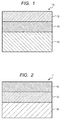
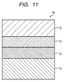
- a transfer material 1 of this embodiment includes the coloring material-receiving layer 53 configured to receive a coloring material, a transparent sheet 52, and the base material sheet 50 configured to support the coloring material-receiving layer 53 and the transparent sheet 52.
- the transfer material includes the coloring material-receiving layer on the base material sheet, and serves as an intermediate sheet upon arrangement of the coloring material-receiving layer on an image support by transfer after the printing of an image on the transfer material.
- the transfer of the coloring material-receiving layer of the transfer material onto the image support enables the formation of the image on the coloring material-receiving layer of the image support.
- the transfer material of this embodiment is a transfer material including the base material sheet 50, the transparent sheet 52, and the coloring material-receiving layer 53 like the transfer material 1 illustrated in FIG. 2 .
- the coloring material-receiving layer is a layer configured to receive the coloring material.
- the coloring material-receiving layer contains at least the inorganic fine particles and the water-soluble resin.
- the following forms are present as preferred forms of the coloring material-receiving layer: a swelling absorption-type coloring material-receiving layer configured to receive the coloring material (such as an ink) in the network structure of a water-soluble polymer; and a gap absorption-type coloring material-receiving layer configured to receive the coloring material in gaps formed by the inorganic fine particles.
- the transfer material of this embodiment includes the gap absorption-type coloring material-receiving layer formed of a composition containing at least the inorganic fine particles and the water-soluble resin.
- the gap absorption-type coloring material-receiving layer can quickly absorb the coloring material with the gaps formed by the inorganic fine particles. Therefore, upon thermal pressure bonding of the transfer material onto the image support, abrupt bumping of the coloring material is reduced, and hence such an inconvenience that the transfer material and the image support are not completely bonded to each other (adhesive property failure), and such an inconvenience that air bubbles remain in a space between the transfer material and the image support (remaining of the air bubbles) can be suppressed.
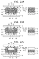
- the incorporation of the inorganic fine particles into the coloring material-receiving layer facilitates the occurrence of a crack in a gap between the inorganic fine particles as illustrated in FIGS. 23A to 23C , and hence can suppress the remaining of a burr in the end portion.
- the coloring material-receiving layer Upon formation of the coloring material-receiving layer, it is preferred to precisely control the average particle diameter of the inorganic fine particles, and the weight-average polymerization degree and saponification degree of the water-soluble resin.
- the transparency (permeability) of the coloring material-receiving layer, and an adhesive strength between the coloring material-receiving layer and the transparent sheet can be improved.
- the visibility of an image from a side closer to the transparent sheet can be improved. Therefore, even when a pigment ink that hardly permeates the coloring material-receiving layer is used as the coloring material, there is no need to increase the thickness of the coloring material-receiving layer for increasing an ink density or for causing the layer to receive a large amount of the ink. Accordingly, the thickness of the transfer material, and by extension, the entire thickness of a recorded matter can be reduced.
- the inorganic fine particles are fine particles formed of an inorganic material.
- the inorganic fine particles have a function of forming a gap configured to receive a coloring material in the coloring material-receiving layer.
- the kind of the inorganic material forming the inorganic fine particles is not particularly limited. However, an inorganic material that has a high ink-absorbing ability, is excellent in color developability, and is capable of forming a high-quality image is preferred. Examples thereof can include calcium carbonate, magnesium carbonate, kaolin, clay, talc, hydrotalcite, aluminum silicate, calcium silicate, magnesium silicate, diatomaceous earth, alumina, colloidal alumina, aluminum hydroxide, a hydrated alumina having a boehmite structure, a hydrated alumina having a pseudoboehmite structure, lithopone (a mixture of barium sulfate and zinc sulfate), and zeolite.
- an inorganic material that has a high ink-absorbing ability, is excellent in color developability, and is capable of forming a high-quality image is preferred. Examples thereof can include calcium carbonate, magnesium carbonate, kaolin, clay, talc, hydrotalcite, aluminum silicate,
- alumina fine particles formed of at least one kind of substance selected from the group consisting of alumina and a hydrated alumina are preferred.
- the hydrated alumina can include a hydrated alumina having a boehmite structure and a hydrated alumina having a pseudoboehmite structure.
- Alumina, the hydrated alumina having a boehmite structure, or the hydrated alumina having a pseudoboehmite structure is preferred because any such material can improve the transparency of the coloring material-receiving layer and the recording density of an image.
- the hydrated alumina having a boehmite structure can be obtained by adding an acid to a long-chain aluminum alkoxide to perform hydrolysis and peptization (see Japanese Patent Application Laid-Open No. S56-120508 ). Any one of an organic acid and an inorganic acid may be used in the peptization. However, nitric acid is preferably used. The use of nitric acid can improve the reaction efficiency of the hydrolysis, can provide a hydrated alumina having a controlled shape, and can provide a dispersion liquid having good dispersibility.
- the average particle diameter of the inorganic fine particles is preferably from 120 nm to 200 nm. Setting the average particle diameter to preferably 120 nm or more, more preferably 140 nm or more can improve the ink absorbability of the coloring material-receiving layer, and hence can suppress the bleeding and beading of the ink in an image after its recording. Meanwhile, setting the average particle diameter to preferably 200 nm or less, more preferably 170 nm or less can suppress light scattering due to the inorganic fine particles, and hence can improve the glossiness and transparency of the coloring material-receiving layer. In addition, the setting can increase the number of the inorganic fine particles per unit area of the coloring material-receiving layer, and hence can improve the ink absorbability. Therefore, the setting can increase the recording density of the image and can suppress the lack of luster of the image after the recording.
- known inorganic fine particles may be used as they are, or the known inorganic fine particles whose average particle diameter and polydispersity index have been adjusted with a pulverization dispersing machine or the like may be used.
- the kind of the pulverization dispersing machine is not particularly limited.
- a conventionally known pulverization dispersing machine such as a high-pressure homogenizer, an ultrasonic homogenizer, a wet media-type pulverizer (a sand mill or a ball mill), a continuous highspeed stirring-type dispersing machine, or an ultrasonic dispersing machine, can be used.
- pulverization dispersing machine can include: Manton-Gaulin homogenizer and Sonolator (each of which is manufactured by Doyei Shoji Co., Ltd.); Microfluidizer (manufactured by MIZUHO INDUSTRIAL Co., Ltd.); Nanomizer (manufactured by Tsukishima Kikai Co., Ltd.); Ultimaizer (manufactured by ITOCHU MACHINE-TECHNOS CORPORATION); PEARL MILL, GRAIN MILL, and TORNADO (each of which is manufactured by ASADA IRON WORKS Co., Ltd.); Visco Mill (manufactured by AIMEX Co., Ltd.); MIGHTY MILL, RS MILL, and S ⁇ MILL (each of which is manufactured by INOUE MFG., INC.); Ebara Milder (manufactured by EBARA CORPORATION); and FINE FLOW MILL and CAVITRON (each of which is manufactured by
- the inorganic fine particles preferably satisfy the range of the average particle diameter and have a polydispersity index (u/ ⁇ > 2 ) of from 0.01 to 0.20, and the inorganic fine particles more preferably have a polydispersity index of from 0.01 to 0.18. Setting the index within the range can keep the sizes of the particles constant, and hence can improve the glossiness and transparency of the coloring material-receiving layer. Therefore, the setting can increase the recording density of an image and can suppress the lack of luster of the image after its recording.
- the average particle diameter and polydispersity index as used herein can be determined by analyzing values measured by a dynamic light scattering method by a cumulant method described in the " Structure of Polymer (2) Scattering Experiment and Morphological Observation Chapter 1 Light Scattering" (KYORITSU SHUPPAN Co., Ltd., edited by The Society of Polymer Science, Japan ) or J. Chem. Phys., 70(B), 15 Apl., 3965 (1979 ).
- dynamic light scattering when fine particles having different particle diameters are mixed, the attenuation of a time correlation function from scattered light has a distribution.
- the average ( ⁇ >) and variance ( ⁇ ) of an attenuation rate are determined by analyzing the time correlation function by the cumulant method.
- the attenuation rate ( ⁇ ) is represented by a function of the diffusion coefficients and scattering vectors of the particles, and hence their hydrodynamic average particle diameter can be determined by using Stokes-Einstein's equation. Therefore, the polydispersity index (u/ ⁇ > 2 ) obtained by dividing the variance ( ⁇ ) of the attenuation rate by the square of its average ( ⁇ > 2 ) represents the extent to which the particle diameters vary, and means that the distribution of the particle diameters narrows as a value for the index approaches 0.
- the average particle diameter and polydispersity index defined in the present invention can be easily measured with, for example, a laser particle diameter analyzer PARIII (manufactured by Otsuka Electronics Co., Ltd.).
- One kind of the inorganic fine particles can be used alone, or two or more kinds thereof can be used as a mixture.
- the term "two or more kinds” comprehends inorganic fine particles different from each other in material itself, and inorganic fine particles different from each other in characteristics, such as an average particle diameter and a polydispersity index.
- the water-soluble resin is a resin that completely mixes with water, or has a solubility in water of 1 (g/100 g) or more, at 25°C.
- the water-soluble resin functions as a binder for binding the inorganic fine particles.
- the water-soluble resin is not particularly limited as long as the water-soluble resin satisfies the following expression (2).
- of 0.6 or more is not preferred because of the following reason: an intermolecular force between the water-soluble resin and the emulsion E1 weakens to reduce the adhesive property between the coloring material-receiving layer and the transparent sheet, and hence peeling occurs between the transparent sheet and the coloring material-receiving layer in a test, such as tape peeling. Setting the
- water-soluble resin can include: starch, gelatin, casein, and modified products thereof; a cellulose derivative, such as methylcellulose, carboxymethylcellulose, or hydroxyethylcellulose; polyvinyl alcohol (e.g., completely saponified, partially saponified, or low saponified polyvinyl alcohol) or modified products thereof (e.g., a cationically modified product, an anionically modified product, and a silanol-modified product); and resins, such as a urea-based resin, a melamine-based resin, an epoxy-based resin, an epichlorohydrin-based resin, a polyurethane-based resin, a polyethylene imine-based resin, a polyamide-based resin, a polyvinylpyrrolidone-based resin, a polyvinyl butyral-based resin, poly(meth)acrylic acid or a copolymer resin thereof, an acrylamide-based resin, a maleic anhydride-based copoly,
- polyvinyl alcohol in particular, saponified polyvinyl alcohol obtained by hydrolyzing (saponifying) polyvinyl acetate is preferred.
- the SP value of the polyvinyl alcohol is close to the SP values of PVC and PET-G. Therefore, when the water-soluble resin and the image support melt with heat at the time of the transfer, compatibility between the water-soluble resin and the image support improves, and hence the water-soluble resin is strongly bonded to the image support.
- the polyvinyl alcohol is particularly preferably used because when the PVC or the PET-G is used as the image support, the polyvinyl alcohol can improve the adhesive property (transfer performance) between the image support and the coloring material-receiving layer.
- the coloring material-receiving layer is preferably formed of a composition containing polyvinyl alcohol having a saponification degree of from 70 mol% to 100 mol%.
- the saponification degree means the percentage of the number of moles of the hydroxyl groups of the polyvinyl alcohol with respect to the total number of moles of the acetic acid groups and hydroxyl groups thereof.
- the saponification degree preferably 70 mol% or more, more preferably 86 mol% or more prevents the coloring material-receiving layer from becoming excessively hard and can impart moderate flexibility to the coloring material-receiving layer. Therefore, the foil-cutting property of the coloring material-receiving layer improves in the peeling step, and hence the occurrence of a burr in the end portion can be suppressed. In addition, the viscosity of a coating liquid containing the inorganic fine particles and the polyvinyl alcohol can be reduced. Therefore, the coating liquid is easily applied to the transparent sheet and hence the productivity of the transfer material can be improved.
- setting the saponification degree to preferably 100 mol% or less, more preferably 90 mol% or less can impart a moderate hardness to the coloring material-receiving layer.
- the adhesive strength between the transparent sheet and the coloring material-receiving layer is improved, and hence the peeling of the coloring material-receiving layer from the transparent sheet due to an insufficient adhesive strength therebetween can be suppressed.
- the setting can impart moderate hydrophilicity to the coloring material-receiving layer and hence improves the absorbability of the ink. Therefore, a high-quality image can be recorded on the coloring material-receiving layer.
- the saponified polyvinyl alcohol that satisfies the range of the saponification degree, there can be given, for example, completely saponified polyvinyl alcohol (saponification degree: from 98 mol% to 99 mol%), partially saponified polyvinyl alcohol (saponification degree: from 87 mol% to 89 mol%), and low saponified polyvinyl alcohol (saponification degree: from 78 mol% to 82 mol%). Of those, partially saponified polyvinyl alcohol is preferred.
- the coloring material-receiving layer is preferably formed of a composition containing polyvinyl alcohol having a weight-average polymerization degree of from 2,000 to 5,000.
- Setting the weight-average polymerization degree to preferably 2,000 or more, more preferably 3,000 or more can impart moderate flexibility to the coloring material-receiving layer. Therefore, the foil-cutting property of the coloring material-receiving layer improves in the peeling step, and hence the occurrence of a burr in the end portion can be suppressed. Meanwhile, setting the weight-average polymerization degree to preferably 5,000 or less, more preferably 4,500 or less can impart a moderate hardness to the coloring material-receiving layer. Thus, the adhesive strength between the transparent sheet and the coloring material-receiving layer is improved, and hence the peeling of the coloring material-receiving layer from the transparent sheet due to an insufficient adhesive strength therebetween can be suppressed.
- the setting can reduce the viscosity of the coating liquid containing the inorganic fine particles and the polyvinyl alcohol. Therefore, the coating liquid can be easily applied to the transparent sheet and hence the productivity of the transfer material can be improved.
- the pores of the coloring material-receiving layer are prevented from being filled, and hence the opening states of the pores can be satisfactorily maintained and the absorbability of the ink improves. Therefore, a high-quality image can be recorded on the coloring material-receiving layer.
- a value for the weight-average polymerization degree is calculated in conformity with a method described in JIS-K-6726.
- One kind of the water-soluble resins can be used alone, or two or more kinds thereof can be used as a mixture.
- the term "two or more kinds” comprehends water-soluble resins different from each other in characteristics, such as a saponification degree and a weight-average polymerization degree.
- the amount of the water-soluble resin is preferably set to from 3.3 parts by mass to 20 parts by mass with respect to 100 parts by mass of the inorganic fine particles. Setting the amount of the water-soluble resin to preferably 3.3 parts by mass or more, more preferably 5 parts by mass or more inhibits the occurrence of the cracking or dusting of the coloring material-receiving layer. Meanwhile, setting the amount of the water-soluble resin to preferably 20 parts by mass or less, more preferably 15 parts by mass or less improves the absorbability of the ink.
- the cationic resin to be used has a cationic atomic group (such as a quaternary ammonium) in a molecule thereof.
- the weight-average molecular weight of the cationic resin is 15,000 or less.
- the cationic resin to be used not only has a SP value close to the SP value of a resin constituting the image support but also easily melts with heat upon thermal pressure bonding of the transfer material onto the image support, and accelerates electrostatic bonding therebetween. Accordingly, the adhesive property between the image support and the coloring material-receiving layer is additionally strengthened, and hence the adhesive property (transfer performance) between the image support and the coloring material-receiving layer can be improved.
- the cationic resin electrostatically bonds to an ink that is in general negatively charged, and hence can fix the ink in the coloring material-receiving layer.
- the cationic resin having a weight-average molecular weight of 15,000 or less (1) is selected to have a SP value close to that of the image support, and hence has a high affinity for the image support, and can improve the adhesive property between the image support and the coloring material-receiving layer at the time of the transfer.
- the cationic resin to be used (2) has a low melting point and easily melts with heat at the time of the transfer, and hence additionally strengthens the adhesive property between the image support and the coloring material-receiving layer.
- the cationic resin to be used (3) has a small molecular weight, and hence many molecules of the resin can be added to the coloring material-receiving layer even when its addition amount to the coloring material-receiving layer is small. Accordingly, a cationic group capable of electrostatically bonding to the image support that is in general negatively charged can be caused to exist on the surface of the coloring material-receiving layer, and as a result, the adhesive property between the image support and the coloring material-receiving layer can be improved. Further, the resin (4) can improve the adhesive property of the coloring material-receiving layer with a resin dispersion pigment.
- the SP value of the dispersing resin of the resin dispersion pigment is close to the SP value of the cationic resin to be used. Accordingly, when the cationic resin and the dispersing resin melt with the heat at the time of the transfer, compatibility between both the resins improves and hence the resin dispersion pigment is strongly bonded to the coloring material-receiving layer. (5) The cationic resin melts with the heat at the time of the transfer to be electrostatically bonded to an emulsion of the transparent sheet in a state of being compatible therewith.
- the cationic resin is strongly bonded to the particulate emulsion E2 having a low adhesive force as well, and hence the adhesive property between the coloring material-receiving layer and the transparent sheet can be additionally improved.
- the transfer performance of the coloring material-receiving layer onto the image support improves. Therefore, the cationic resin to be used serves to improve the transfer performance of the coloring material-receiving layer onto the image support by virtue of the five effects.
- At least one kind of polymer selected from a polyallylamine (such as an allylamine-based polymer or a diallylamine-based polymer) and a urethane-based polymer is preferably used as such cationic resin.
- a polyallylamine such as an allylamine-based polymer or a diallylamine-based polymer
- a urethane-based polymer is preferably used as such cationic resin.
- a low-molecular polyallylamine can be particularly preferably used because of, for example, the following reasons: (1) the polyallylamine has a melting point as low as around 80°C and hence easily melts upon thermal pressure bonding of the transfer material onto the image support; and (2) the polyallylamine has a small molecular structure, and hence can cause many cationic groups to be present per unit area of the surface of the coloring material-receiving layer and can accelerate its electrostatic bonding to the image support.
- the polyallylamine is preferably at least one kind of polyallylamine represented by the following general formula (3).
- R 3 , R 4 , and R 5 each represent a hydrogen atom, an alkyl group, an alkenyl group, an alkanol group, an allylalkyl group, or an allylalkenyl group that may have a substituent, provided that R 3 , R 4 , and R 5 may be identical to or different from each other;
- X- represents an inorganic or organic anion; and
- n represents an integer, which indicates a polymerization degree.
- the weight-average molecular weight of the cationic resin is preferably from 1,000 to 15,000, more preferably from 1,000 to 10,000, particularly preferably from 1,000 to 5,000. Setting the average molecular weight within the range can improve the stability of the coating liquid. In addition, the number of the gaps of the coloring material-receiving layer hardly reduces and hence the absorbability of the coloring material can be maintained. Further, setting the average molecular weight of the cationic resin to 5,000 or less can distribute a larger number of cationic groups (that is, adsorption sites for performing the electrostatic bonding) on the surface of the coloring material-receiving layer to be brought into contact with the image support.
- the adhesive property (transfer performance) between the image support and the coloring material-receiving layer can be additionally improved. It should be noted that when the average molecular weight becomes larger than 15,000, the number of the cationic groups (that is, the adsorption sites for performing the electrostatic bonding) on the surface of the coloring material-receiving layer to be brought into contact with the image support reduces. Accordingly, the adhesive property (transfer performance) of the image support with the coloring material-receiving layer reduces.
- a weight-average molecular weight of less than 1,000 is not preferred because the cationic resin moves toward the inside of the coloring material-receiving layer together with the solvent of the ink at the time of printing, and hence the amount of the cationic groups distributed in the surface of the coloring material-receiving layer reduces.
- the usage amount of the cationic resin is set to preferably 0.01 mass% or more and 5 mass% or less, more preferably 0.01 mass% or more and 3 mass% or less with respect to the inorganic fine particles (such as a hydrated alumina).
- the usage amount of the cationic resin deviates from the range, the viscosity of the dispersion liquid of the inorganic fine particles or of the coating liquid obtained by adding the binder to the dispersion liquid increases, and hence the storage stability and applicability of the dispersion liquid or the coating liquid reduce in some cases.
- the melting point of the cationic resin is preferably 60°C or more and 160°C or less. Setting the melting point of the cationic resin within the range can melt the cationic resin upon thermal pressure bonding of the transfer material onto the image support, and hence can improve the adhesive property (transfer performance) between the image support and the coloring material-receiving layer.
- the thickness of the coloring material-receiving layer is not particularly limited. However, the thickness of the coloring material-receiving layer is preferably from 5 ⁇ m to 40 ⁇ m. Setting the thickness of the coloring material-receiving layer to preferably 10 ⁇ m or more, more preferably 15 ⁇ m or more can secure the absorbability of the ink and the transparency of the coloring material-receiving layer. In addition, the setting improves the absorbability of the ink and the fixability of the ink. Meanwhile, setting the thickness of the coloring material-receiving layer to preferably 40 ⁇ m or less, more preferably 20 ⁇ m or less can improve the transparency of the coloring material-receiving layer.
- the setting can improve heat conduction when thermal pressure bonding onto the image support, and hence can improve the adhesive property (transfer performance) between the image support and the coloring material-receiving layer.
- the setting facilitates the reduction of the thickness of the entirety of the recorded matter to a total thickness of 0.84 mm, which is described in JIS 6301, or less.
- the transfer material of this embodiment includes the transparent sheet 52 like the transfer material 1 illustrated in FIG. 2 .
- the transparent sheet 52 of this embodiment contains the emulsion E1 and the emulsion E2.
- the emulsion E1 and the emulsion E2 are described in more detail below.
- This embodiment is a state in which the emulsion E1 forms a film and at least the emulsion E2 remains as particles.
- the "film-forming state" of an emulsion means a state in which the emulsion is subjected to a heat treatment at a temperature equal to or more than its glass transition temperature.
- the "particle state” of an emulsion means a state in which the emulsion is not subjected to any heat treatment at a temperature equal to or more than its glass transition temperature.
- a drying temperature after the application of the emulsions is set to the glass transition temperature Tg1 of the emulsion E1 or more and less than the glass transition temperature Tg2 of the emulsion E2.
- the film states of the transparent sheet portion 980 of the portion 963 where the image support 55 and the coloring material-receiving layer are bonded to each other, and the transparent sheet portion 981 of the portion 964 where the image support and the coloring material-receiving layer are not bonded to each other can be controlled to differ from each other at the time of thermal pressure bonding. That is, at the time of the thermal pressure bonding, the heat of a heat roll is easily transferred to the transparent sheet portion 980, and hence a state in which part of the emulsion E2 turns into a film and part of its particles remain ( FIG.
- the foil-cutting property can be improved by using the two kinds of emulsions and changing the film state of the emulsion E2 through the utilization of a temperature at the time of the thermal pressure bonding.
- a heat treatment is performed at a temperature equal to or more than the Tg2 in a manufacturing process, both the emulsion E1 and the emulsion E2 are brought into states of turning into films to make it difficult for a crack to occur in the boundary portion 982 of transfer, and hence a sufficient cutting property of the end portion is not obtained.
- a heat treatment is performed at a temperature equal to or less than the Tg1, both the emulsion E1 and the emulsion E2 are brought into particle states, and hence the transparent sheet cannot be formed.
- a glass transition temperature (Tg) is such a temperature that when an amorphous solid is heated, the solid that is as hard as a crystal (has a large modulus of rigidity) and does not have flowability (its viscosity is too large to be measured) at low temperature is rapidly reduced in rigidity and viscosity in a certain narrow temperature range to be increased in flowability.
- the glass transition temperature Tg refers to a value calculated from Fox's equation based on the glass transition temperature (Tg) of a homopolymer of each monomer and the mass fraction (copolymerization ratio on a mass basis) of the monomer.
- the unit of a numerical value representing a glass transition temperature is "°C" unless otherwise stated.
- Tg of homopolymers Values described in known materials are adopted as the Tg of homopolymers. In the technology disclosed herein, the following values are specifically used as the Tg of the homopolymers. 2-Ethylhexyl acrylate -70°C n-Butyl acrylate -55°C Ethyl acrylate -22°C Methyl acrylate 8°C Methyl methacrylate 105°C Isobornyl acrylate 94°C Isobornyl methacrylate 180°C Vinyl acetate 32°C 2-Hydroxyethyl acrylate -15°C Styrene 100°C Acrylic acid 106°C Methacrylic acid 130°C
- the emulsion E1 is in a film-forming state at the time of the formation of the transparent sheet.
- the film-forming state can be established by subjecting the emulsion E1 to a heat treatment at a temperature equal to or more than the glass transition temperature Tg1. Causing the emulsion E1 to form a film can increase an area of contact with the coloring material-receiving layer, improves the adhesive property between the transparent sheet and the coloring material-receiving layer, and can perform such control that peeling does not occur between the protective layer and the coloring material-receiving layer in a test, such as tape peeling.
- the glass transition temperature Tg1 of the emulsion E1 is preferably more than 50°C and less than 90°C.
- the Tg1 is more preferably more than 55°C and less than 80°C, still more preferably more than 55°C and less than 70°C. Setting the Tg1 to preferably more than 50°C, more preferably more than 55°C increases the glass transition temperature of the emulsion E1 to harden the film portion of the transparent sheet, thereby making the portion hard to stretch.
- the film is suppressed in stretching at the time of the cutting of the end portion and the end portion can be kept beautiful, and hence the cutting property of the end portion improves.
- controlling the Tg1 within the range makes it hard for the resin to adapt to the oils and fats or sweat of a hand, and suppresses the stretching property of the film, thereby exhibiting the following effect: even when the hand is in contact with the transparent sheet, the transparent sheet is hardly brought into close contact with the hand and hence the stickiness of the transparent sheet is suppressed. Further, increasing the Tg1 strengthens a force acting between the molecular chains of the emulsion resin to make the emulsion hardly soluble in a chemical, such as an alcohol, and hence can significantly improve the chemical resistance of a recorded matter.
- setting the Tg1 to preferably less than 90°C, more preferably less than 80°C, still more preferably less than 70°C facilitates the performance of the film formation at the time of the formation of the transparent sheet, and hence can improve the adhesive property between the transparent sheet and the coloring material-receiving layer. Further, the setting alleviates the brittleness of the film and hence can prevent, for example, the peeling of the transparent sheet in a water resistance test. In addition, it is difficult to completely keep a drying temperature constant in terms of an actual manufacturing process, and hence the drying temperature varies to some extent.
- the drying temperature varies, when values for the Tg1 and the Tg2 are close to each other, excessive heat is applied at the time of an attempt to turn the emulsion E1 into a film, and hence the drying temperature may exceed the Tg2 to make it difficult to maintain the film state of the emulsion E1 and the particle state of the emulsion E2. Therefore, it is preferred that the Tg1 and the Tg2 satisfy a relationship represented by the following expression (5), and hence the Tg2 and the Tg1 differ from each other by about 10°C because even when the drying temperature varies, no excessive heat is applied, and hence the film state of the emulsion E1 and the particle state of the emulsion E2 are easily maintained.
- Tg1 When the Tg1 becomes 50°C or less, the resin adapts to the oils and fats or sweat of the hand, and hence the stickiness occurs. In addition, when the transfer material is turned into a roll shape, blocking is liable to occur. When the Tg1 becomes 90°C or more, it becomes difficult for the emulsion E1 to form a film, and hence the adhesive property between the transparent sheet and the coloring material-receiving layer reduces, and the peeling of the transparent sheet is liable to occur. Further, the film becomes brittle and hence the peeling of the transparent sheet in the water resistance test is liable to occur. Tg 2 ⁇ Tg 1 ⁇ 10
- the absolute value of a difference ⁇ SP between the SP value of the emulsion E1 of the transparent sheet and the SP value of the water-soluble resin of the coloring material-receiving layer preferably satisfies the following expression (2).
- their SP values become closer to each other, their compatibility improves, and hence the sheet and the layer show a higher adhesive property. Setting the absolute value within the range improves the compatibility of the emulsion E1 with the water-soluble resin, and shortens an intermolecular distance between the emulsion E1 that has turned into a film and the water-soluble resin.
- the setting increases an intermolecular force therebetween, improves the adhesive property between the transparent sheet and the coloring material-receiving layer, and can make it additionally difficult for peeling to occur between the protective layer and the coloring material-receiving layer in a test, such as tape peeling.
- a ⁇ SP of more than 0.6 is not preferred because of the following reason: the compatibility reduces, the intermolecular distance between the emulsion E1 that has turned into a film and the water-soluble resin lengthens, and the intermolecular force reduces, and hence a reduction in adhesive force occurs. 0 ⁇
- the SP value represents a solubility parameter and is also referred to as "Hildebrand parameter.”
- the solubility parameter is used as a measure representing an intermolecular force because in a regular solution theory, it is hypothesized that a force acting between a solvent and a solute is the intermolecular force alone.
- An actual solution is not necessarily a regular solution, but it has been empirically known that as a difference in SP value between the two components becomes smaller, a solubility becomes larger.
- the SP value is represented by the following general expression (7).
- Typical SP values are shown in Table 1.
- the SP values shown in Table 1 are transcribed from the SP values of various plastics described in " Plastic Processing Technology Handbook", June 12, 1995, edited by The Society of Polymer Science, Japan, published by Nikkan Kogyo Shimbun, Ltd., p. 1474, Table 3.20 .
- the ⁇ ei and the ⁇ vi in the expression (8) show constant numerical values given to i atoms or groups in a main molecule.
- typical examples of numerical values for ⁇ e and ⁇ v given to an atom or a group are shown in Table 2 below.
- a material for the emulsion E1 is preferably a resin, such as an acrylic resin, a vinyl acetate-based resin, a vinyl chloride-based resin, an ethylene/vinyl acetate-based resin, a polyamide resin, a polyester resin, a polyurethane resin, or a polyolefin resin, or a copolymer resin thereof.
- an acrylic resin is particularly preferably used because of the following reasons: the resin can be formed into a film at relatively low temperature; the transparency of an applied film thereof is high; and the resin has a SP value close to that of the saponified polyvinyl alcohol to be incorporated as the water-soluble resin, and hence can improve the adhesive property.
- the acrylic resin is a relatively hard resin and exhibits the following effect: the resin suppresses the stretching property of the film to improve the cutting property of the end portion.
- a (meth)acrylate alone or a copolymer using the (meth)acrylate can be used as the acrylic resin.
- Specific examples of the (meth)acrylate can include methyl (meth)acrylate, ethyl (meth)acrylate, isopropyl (meth)acrylate, n-butyl (meth)acrylate, n-hexyl (meth)acrylate, n-octyl (meth)acrylate, 2-ethylhexyl (meth)acrylate, isononyl (meth)acrylate, and lauryl (meth)acrylate.
- One kind of those (meth)acrylates can be used alone, or two or more kinds thereof can be used in combination.
- those (meth)acrylates can be used through additional polymerization with a monomer that is copolymerizable therewith.
- monomer which are described in Japanese Patent Application Laid-Open No. 2002-121515 , can include: unsaturated carboxylic acids, such as (meth) acrylic acid, crotonic acid, maleic acid, fumaric acid, and itaconic acid; monomers each having a hydroxyl group, such as hydroxylethyl (meth)acrylate, hydroxylpropyl (meth)acrylate, and hydroxylbutyl (meth)acrylate; monomers each having an alkoxy group, such as methoxyethyl (meth)acrylate and ethoxyethyl (meth)acrylate; monomers each having a glycidyl group, such as glycidyl (meth)acrylate and allyl glycidyl ether; monomers each having a nitrile group, such as (meth)acryl
- the emulsion to be used in this embodiment can be synthesized by a generally well-known technology, and a commercial material can be used.
- the Tg of the resin to be used in the emulsion can be adjusted by changing a monomer component thereof and its ratio.
- the emulsion E1 may be one kind of emulsion, or a blend of a plurality of kinds of emulsions may be used.
- the emulsion E2 is in a particle state at the time of the formation of the transparent sheet.
- the "particle state" can be established by maintaining the original particle state of the emulsion without applying any heat treatment at the glass transition temperature Tg2 of the emulsion E2 or more. Bringing the emulsion E2 into the particle state improves the cutting property of the end portion at the time of the transfer and hence can suppress the stickiness of the transparent sheet.
- the glass transition temperature Tg2 of the emulsion E2 is preferably 90°C or more and 120°C or less, more preferably from 95°C to 115°C, still more preferably from 100°C to 110°C. Setting the glass transition temperature Tg2 of the emulsion E2 to preferably 90°C or more, more preferably 95°C or more, still more preferably 100°C or more enlarges the difference in film strength between the emulsion that is incorporated into the transparent sheet portion 980 of the portion 963 where the image support 55 and the coloring material-receiving layer are bonded to each other, and that melts and softens with heat at the time of the heat transfer to be brought into a film state, and the emulsion in the particle state incorporated into the transparent sheet portion 981 of the portion 964 where the image support and the coloring material-receiving layer are not bonded to each other.
- a crack easily occurs in the boundary portion 982, and hence no burr occurs in the end portion and its foil-cutting property can be improved.
- setting the Tg2 within the range makes it hard for the resin of the emulsion E2 to stretch and to adapt to the oils and fats, and sweat of a hand, and hence can prevent the stickiness of the transparent sheet.
- setting the Tg2 within the range reduces the solubility of the emulsion in a chemical, such as an alcohol, and hence improves its chemical resistance.
- setting the glass transition temperature Tg2 of the emulsion E2 to preferably 120°C or less, more preferably 115°C or less, still more preferably 110°C or less can efficiently control a thermal energy in the thermal pressure bonding to a low energy, and hence can prevent the heat deformation of the image support due to the application of an excessive thermal energy thereto.
- setting the glass transition temperature of the polyvinyl alcohol (PVA) serving as the water-soluble resin of the coloring material-receiving layer can transfer the coloring material-receiving layer onto the image support.
- the coloring material-receiving layer is heated to about 90°C at the time of the thermal pressure bonding of the coloring material-receiving layer onto the image support.
- the transparent sheet close to a heat roll side is heated to the Tg2 or more, and hence the emulsion E2 can be turned into a film and transferred without the application of an excessive thermal energy at the time of the transfer.
- the Tg2 becomes less than 90°C, the emulsion is liable to adapt to the oils and fats or sweat of the hand, and hence the transparent sheet is liable to be sticky and its blocking is liable to occur. Further, a crack hardly occurs and hence the foil-cutting property reduces.
- the emulsion when the Tg2 becomes less than 90°C, the emulsion is liable to dissolve in a chemical, such as an alcohol, and hence its protective performance against the chemical largely reduces.
- a chemical such as an alcohol
- the Tg2 becomes more than 120°C a high energy is required as the thermal energy in the thermal pressure bonding, and hence the heat deformation of the image support due to the application of an excessive thermal energy thereto is liable to occur.
- the same polymer substance as that for the emulsion E1 can be used as a polymer substance constituting the emulsion E2 of this embodiment.
- an acrylic resin and a urethane-based resin are preferably used because a difference SP1 in SP value between the transparent sheet and the base material sheet can be controlled to 1.1 or more, and hence the peelability from the base material sheet improves.
- the emulsion E2 is particularly preferably the urethane-based resin.
- the urethane-based resin has moderate softness and hence suppresses the stickiness.
- the resin alleviates the brittleness of the film and reduces its solubility in a chemical, and hence can improve the chemical resistance, and for example, even when it is immersed in a chemical, such as an alcohol, its cracking and peeling hardly occur.
- a resin of a kind different from that of the emulsion E1 is preferably used as the emulsion E2, and the use of resins of different kinds makes it difficult for the resins to be compatible with each other, and hence facilitates the maintenance of a state in which the film and particles coexist in a state before the transfer.
- the acrylic resin is used as the emulsion E1
- the emulsion E2 is particularly preferably the urethane-based resin.
- urethane-based resin can include urethane-based resins synthesized from various combinations of polyol compounds and diisocyanate compounds listed below by polyaddition reactions.
- the urethane-based resin is not particularly limited, but is preferably a polyether urethane-based resin synthesized from a polyether-based polyol compound and a diisocyanate compound.
- the polyether urethane-based resin improves the durability of the recorded matter including water resistance because the resin hardly hydrolyzes.
- a diol containing two hydroxyl groups, or a polyol containing three or more hydroxyl groups can be used as the polyol compound without any particular limitation.
- one kind of the following polyols may be used alone, or two or more kinds thereof may be used in combination: polyols such as polyether-based, polyester-based, polycarbonate-based, acrylic, polybutadiene-based, and polyolefin-based polyols; and polyols such as a caprolactone-modified polyol, a polyester amide polyol, a polyurethane polyol, an epoxy polyol, an epoxy-modified polyol, an alkyd-modified polyol, castor oil, and a fluorine-containing polyol.
- polyether-based polyol examples include: polyhydric alcohols, such as ethylene glycol, propylene glycol, butylene glycol, tetramethylene glycol, glycerin, trimethylolpropane, pentaerythritol, sorbitol, and sucrose; aliphatic amine compounds, such as ethylenediamine; aromatic amine compounds, such as toluenediamine and diphenylmethane-4,4-diamine; and polyols each obtained by subjecting a compound having at least two or more active hydrogen groups, such as an alkanolamine, e.g., ethanolamine or diethanolamine, which serves as a starting raw material, to addition with an alkylene oxide typified by ethylene oxide, propylene oxide, butylene oxide, or polyoxytetramethylene oxide.
- polyhydric alcohols such as ethylene glycol, propylene glycol, butylene glycol, tetramethylene glycol, glycerin
- polyester-based polyol examples include: condensation polymers of at least one kind selected from ethylene glycol, propylene glycol, butanediol, pentanediol, hexanediol, glycerin, 1,1,1-trimethylolpropane, and other low-molecular polyols and at least one kind selected from glutaric acid, adipic acid, pimelic acid, suberic acid, sebacic acid, dimeric acid, and other low-molecular aliphatic carboxylic acids and oligomeric acids; and ring-opened polymers, such as propiolactone and valerolactone.
- polys except the polyether-based and polyester-based polyols there are given, for example: a polymer polyol; a polycarbonate polyol; a polybutadiene polyol; a hydrogenated polybutadiene polyol; an acrylic polyol; and low-molecular polyols, such as ethylene glycol, diethylene glycol, propylene glycol, dipropylene glycol, butanediol, pentanediol, and hexanediol.
- a polymer polyol such as ethylene glycol, diethylene glycol, propylene glycol, dipropylene glycol, butanediol, pentanediol, and hexanediol.
- the diisocyanate compound can be used without any particular limitation.
- Examples of the diisocyanate compound may include methylene diisocyanate, ethylene diisocyanate, isophorone diisocyanate, hexamethylene diisocyanate, 1,4-cyclohexane diisocyanate, 2,4-toluene diisocyanate, 2,6-toluene diisocyanate, 1,3-xylylene diisocyanate, 1,5-naphthalene diisocyanate, m-phenylene diisocyanate, p-phenylene diisocyanate, 3,3'-dimethyl-4,4'-diphenylmethane diisocyanate, 3,3'-dimethylbiphenylene diisocyanate, 4,4'-biphenylene diisocyanate, dicyclohexylmethane diisocyanate, and methylenebis(4-cyclohexyl isocyanate).
- the average particle diameter of the emulsion E2 is not particularly limited, but is preferably from 1 nm to 200 nm, more preferably from 5 nm to 150 nm, still more preferably from 10 nm to 50 nm. Setting the average particle diameter to preferably 1 nm or more, more preferably 5 nm or more, still more preferably 10 nm or more enlarges the difference in film strength between the emulsion that is incorporated into the transparent sheet portion 980 of the portion 963 where the image support 55 and the coloring material-receiving layer are bonded to each other, and that melts and softens with the heat at the time of the heat transfer to be brought into a film state, and the emulsion in the particle state incorporated into the transparent sheet portion 981 of the portion 964 where the image support and the coloring material-receiving layer are not bonded to each other.
- the emulsion E2 is maintained in the particle state and hence the particle diameter of the emulsion E2 largely affects the transparency of the transparent sheet. Setting the average particle diameter of the emulsion E2 to preferably 200 nm or less, more preferably 150 nm or less, still more preferably 50 nm or less can improve the transparency of the transparent sheet. Further, when the average particle diameter is equal to or less than the foregoing value, a fine crack easily occurs and hence the cutting property of the end portion improves.
- the average particle diameter of the emulsion E2 When the average particle diameter of the emulsion E2 is less than 1 nm, their particles are so small that the transparent sheet is brought into a state close to a film, and hence a crack hardly occurs at the time of the transfer and the foil-cutting property reduces. When the average particle diameter of the emulsion E2 is more than 200 nm, the transparency reduces.
- the ratio (E1/E2) of the emulsion E1 to the emulsion E2 preferably satisfies the following expression (1), more preferably satisfies a relationship of 5.0 ⁇ E1/E2 ⁇ 50.0, and still more preferably satisfies a relationship of 10.0 ⁇ E1/E2 ⁇ 35.0. Setting the ratio E1/E2 to preferably 65.0 or less, more preferably 50.0 or less, still more preferably 35.0 or less increases the amount of the emulsion E2.
- a crack easily occurs in the boundary portion 982, and hence no burr occurs in the end portion and its foil-cutting property can be improved.
- setting the ratio E1/E2 to preferably 3.0 or more, more preferably 5.0 or more, still more preferably 10.0 or more increases the amount of the emulsion E1.
- the film strength increases.
- an area of contact with the coloring material-receiving layer increases, and hence the adhesive property between the coloring material-receiving layer and the transparent sheet can be improved.
- setting the ratio E1/E2 within the range of from 10.0 to 35.0 can achieve all of the adhesive property, the cutting property of the end portion, and the prevention of cracking at high levels.
- the ratio E1/E2 becomes more than 65.0, the amount of the particle component reduces and the state is brought close to a film state, and hence a crack hardly occurs and the foil-cutting property is not obtained.
- the ratio E1/E2 becomes less than 3.0, the amount of the emulsion E1 serving as a binder for the emulsion E2 reduces. Accordingly, the peeling or dusting of an emulsion of the transparent sheet may occur at the time of the formation of the coloring material-receiving layer, and the coloring material-receiving layer cannot be uniformly formed. Further, the amount of the film-forming component reduces, and hence the adhesive property with the coloring material-receiving layer reduces and the peeling of the transparent sheet is liable to occur. 3.0 ⁇ E 1 / E 2 ⁇ 65.0
- the ratio (E1/E2) between the emulsions E1 and E2 becomes less than 10 (the ratio of the emulsion E2 becomes more than 9.1%)
- the transparent sheet cannot resist shrinkage at the time of the drying of the coloring material-receiving layer upon application of the coloring material-receiving layer onto the transparent sheet, and hence the cracking of the transparent sheet may be liable to occur.
- the phenomenon is peculiar to the transfer material of a type including the coloring material-receiving layer, and occurs only when an aqueous coating liquid containing a water-soluble compound and inorganic fine particles is applied onto the transparent sheet.
- the phenomenon does not occur in a transfer material formed only of a base material and a protective layer.
- a transfer material to be preferably used in an inkjet system its coloring material-receiving layer needs to be caused to absorb a large amount of an ink, and hence the thickness of the coloring material-receiving layer increases, and the coating weight and shrinkage amount at the time of the drying also increase in association with the increase. Accordingly, the cracking at the time of the application is liable to occur.
- the emulsion resin E1 having a glass transition temperature Tg1 of more than 50°C is used as an emulsion that has turned into a film in the transparent sheet in consideration of the adhesive property, the foil-cutting property, the chemical resistance, and the prevention of the stickiness, the emulsion resin hardens and becomes hard to stretch. Thus, the cracking phenomenon tends to be extremely liable to occur owing to the shrinkage.
- the transparent sheet contains the emulsions E1 and E2, the glass transition temperature Tg1 of the emulsion E1 that has turned into a film is more than 50°C, and the emulsion E2 is caused to remain as particles, it is important that the ratio between the emulsions E1 and E2 be precisely controlled.
- an emulsion may be added to the transparent sheet of this embodiment.
- an emulsion having a glass transition temperature of more than 120°C may be added.
- the addition of an emulsion having a higher glass transition temperature can reliably cause a proper amount of the particles to remain in the transparent sheet of the recorded matter even when transferring at high temperature.
- an area of contact between the base material and the transparent sheet reduces to improve its peelability from the base material, and hence its transferability can be improved.
- the addition of one more kind of emulsion in addition to the emulsions E1 and E2 increases the degree of freedom in selection of an emulsion in a film state or a particle state, and hence can impart any other function to the transparent sheet.
- the transparent sheet 52 of this embodiment When the transparent sheet 52 of this embodiment is brought into abutment with the base material sheet, such a material that the difference SP1 between the SP value of the base material sheet and the SP value of the transparent sheet satisfies the following expression (10) is preferably selected. Causing the difference SP1 between the SP value of the base material sheet and the SP value of the layer of the transfer material to be brought into abutment with the base material sheet to satisfy the relationship represented by the following expression (10) leads to the lamination of the transparent sheet and the base material sheet in a state in which an adhesive property therebetween is relatively weak.
- the transfer material of this embodiment when the transfer material of this embodiment is thermally pressure-bonded onto the image support and the base material sheet is peeled, the image recorded on the coloring material-receiving layer can be viewed as an original image through the transparent sheet.
- the transparent sheet when the transfer material is thermally pressure-bonded onto the image support, the transparent sheet functions as a protective layer for the image recorded on the coloring material-receiving layer.
- the transparent sheet means a sheet having a total light transmittance measured in conformity with JIS K 7375 of 50% or more, preferably 90% or more. Therefore, in addition to a colorless transparent sheet, for example, a semitransparent sheet and a colored transparent sheet are included in the transparent sheet.
- the thickness of the transparent sheet is not particularly limited.
- the thickness of the transparent sheet layer is preferably from 1 ⁇ m to 40 ⁇ m, more preferably from 2 ⁇ mto 30 ⁇ m, still more preferably from 4 ⁇ m to 20 ⁇ m. Setting the thickness of the transparent sheet to preferably 1 ⁇ mor more, more preferably 2 ⁇ m or more, still more preferably 4 ⁇ m or more can secure the water resistance and scratch resistance of the transparent sheet. In addition, meanwhile, setting the thickness of the transparent sheet to preferably 40 ⁇ m or less, more preferably 30 ⁇ m or less, still more preferably 20 ⁇ m or less can improve the transparency of the transparent sheet.
- the setting can improve heat conduction at the time of the thermal pressure bonding, and hence can improve the adhesive property (transfer performance) between the transparent sheet and the coloring material-receiving layer.
- the setting is preferred because when a plastic card is used as the image support, the setting facilitates the reduction of the thickness of the entirety of the recorded matter to a total thickness of 0.84 mm, which is described in JIS 6301, or less.
- the transparent sheet preferably contains a UV-cutting agent for preventing the decomposition (photodegradation) of a dye due to UV light.
- a UV-cutting agent for preventing the decomposition (photodegradation) of a dye due to UV light.
- the UV-cutting agent can include: UV absorbers, such as a benzotriazole-based compound and a benzophenone-based compound; and UV-scattering agents, such as titanium oxide and zinc oxide.
- the transfer material of this embodiment includes the base material sheet 50 like the transfer material 1 illustrated in FIG. 2 .
- the base material sheet (also referred to as "release liner” or “separator”) is a sheet body serving as a support for a releasing layer or the coloring material-receiving layer.
- a material for, and the shape of, the base material sheet such a material that the difference SP1 between the SP value of the base material sheet and the SP value of the coloring material-receiving layer satisfies the expression (10) is preferred, and such base material sheet can be, for example, a resin film.
- a resin film that has been utilized as the base material film of a conventional thermal transfer sheet can be utilized as it is.
- Resin films formed of, for example, the following resins are preferred: polyester (such as PET), nylon (aliphatic polyamide), polyimide, cellulose acetate, cellophane, polyethylene, polypropylene, polystyrene, polycarbonate, polyvinyl alcohol, polyvinyl chloride, polyvinylidene chloride, chlorinated rubber, a fluororesin, and an ionomer.
- polyester such as PET
- nylon aliphatic polyamide
- polyimide polyimide
- cellulose acetate cellophane
- polyethylene polyethylene
- polypropylene polystyrene
- polycarbonate polyvinyl alcohol
- polyvinyl chloride polyvinylidene chloride
- chlorinated rubber chlorinated rubber
- fluororesin a fluororesin
- polyvinyl alcohol is used as the water-soluble resin forming the coloring material-receiving layer and the PET film is used as the base material sheet is preferred because a difference between the SP value of the PET and the SP value of the polyvinyl alcohol or the cationic resin is relatively large, and hence a value for the SP1 can be enlarged.
- One kind of the resin films can be used alone, or two or more kinds thereof can be used as a composite or a laminate.
- the thickness of the base material sheet only needs to be appropriately determined in consideration of, for example, its material strength, and is not particularly limited.
- the thickness of the base material sheet is preferably from 5 ⁇ m to 200 ⁇ m.
- the thickness of the base material sheet is set to preferably 5 ⁇ m or more, more preferably 10 ⁇ m or more, upon lamination of the coloring material-receiving layer, the resultant laminate can be prevented from curling.
- the thickness of the transfer material is preferably 15 ⁇ m or more in order to improve the conveyability of the transfer material on a manufacturing apparatus.
- the thickness of the transfer material is preferably 30 ⁇ m or more from the viewpoint of preventing the curling of the cut sheet.
- the thickness of the base material sheet can improve heat transferability in the case of the thermal pressure bonding of the transfer material onto the image support.
- the transfer material of this embodiment may include a releasing layer 51 like the transfer material 1 illustrated in FIG. 3 .
- the releasing layer is a layer formed of a composition containing a release agent, and is arranged between the base material sheet 50 and the transparent sheet 52.
- the transfer material includes the releasing layer 51, the base material sheet 50 can be easily peeled from the transparent sheet 52.
- the releasing layer is not particularly limited, but a releasing layer described in Japanese Patent Application Laid-Open No. 2015-110321 can be preferably used.
- the transfer material of this embodiment may further include an anchor layer 59 like the transfer material 1 illustrated in FIG. 3 .
- the anchor layer 59 is arranged between the transparent sheet 52 and the coloring material-receiving layer 53.
- the adhesive property and adhesive strength between the transparent sheet and the coloring material-receiving layer can be improved, and hence the following inconvenience can be suppressed: the coloring material-receiving layer peels from the transparent sheet owing to an insufficient adhesive strength therebetween.
- the anchor layer is not particularly limited, but an anchor layer described in Japanese Patent Application Laid-Open No. 2015-110321 can be preferably used.
- the transfer material of this embodiment may further include a hologram layer 58 like the transfer material 1 illustrated in FIG. 3 .
- the hologram layer 58 is a layer having recorded thereon a three-dimensional image, and is arranged between the transparent sheet 52 and the coloring material-receiving layer 53.
- a preventing effect on the forgery of a recorded matter (such as a credit card) is imparted to the transfer material.
- the hologram layer is not particularly limited and a conventionally known hologram layer can be adopted.
- a hologram layer described in Japanese Patent Application Laid-Open No. 2015-110321 can be preferably used.
- the transfer material of this embodiment has a laminated structure in which the base material sheet 50, the transparent sheet 52, and the coloring material-receiving layer 53 are laminated in the stated order like the transfer material 1 illustrated in FIG. 2 .
- the phrase "the base material sheet, the transparent sheet, and the coloring material-receiving layer are laminated in the stated order" means that the base material sheet, the transparent sheet, and the coloring material-receiving layer are laminated in accordance with the stated order irrespective of whether or not any other layer is interposed between the base material sheet and the transparent sheet or between the transparent sheet and the coloring material-receiving layer.
- the transfer material of this embodiment preferably has a laminated structure in which the base material sheet 50, the transparent sheet 52, and the coloring material-receiving layer 53 are brought into abutment with one another like the transfer material 1 illustrated in FIG. 2 . That is, a structure in which no other layers (including sheets) are interposed between the base material sheet 50 and the transparent sheet 52, and between the transparent sheet 52 and the coloring material-receiving layer 53 is preferred. This is because of the following reason. There are strict limitations on the thicknesses of a credit card and the like each serving as an object of the recorded matter. Accordingly, the recorded matter is desirably thinned by reducing the number of layers or sheets to be laminated.
- the adhesive strength between the transparent sheet and the coloring material-receiving layer is significantly improved by precisely adjusting the weight-average polymerization degree and saponification degree of the polyvinyl alcohol in the coloring material-receiving layer, and hence there is no need to form the releasing layer or the anchor layer.
- Such construction has an advantage in that the transfer material, and by extension, the recorded matter can be thinned.
- the transfer material of this embodiment further includes the releasing layer 51, the anchor layer 59, or the hologram layer 58 like the transfer material 1 illustrated in FIG. 3
- the transfer material preferably has a laminated structure in which the coloring material-receiving layer 53, the anchor layer 59, the hologram layer 58, the transparent sheet 52, the releasing layer 51, and the base material sheet 50 are laminated in the stated order.
- the transfer material may have a roll shape or a sheet shape (cut sheet shape) in accordance with the structure of an image-recording apparatus or an apparatus for manufacturing the recorded matter.
- the coloring material-receiving layer may be arranged on an outer side or an inner side.
- the transfer material is preferably an outside-front roll-shaped transfer material rolled into a roll shape in which the coloring material-receiving layer is arranged on the outer side and the base material sheet is arranged on the inner side in order that the transfer material may be optimized for the conveying mechanism of the image-recording apparatus.
- the transfer material is preferably an inside-front roll-shaped transfer material rolled into a roll shape in which the coloring material-receiving layer is arranged on the inner side and the base material sheet is arranged on the outer side in order that dirt may be prevented from adhering to the coloring material-receiving layer.
- the outside-front and the inside-front can each be properly used in accordance with applications.
- the thickness of the base material sheet is preferably from 1.5 times to 5 times as large as the thickness of the coloring material-receiving layer.
- Setting the former thickness to a value 1.5 times or more as large as the latter thickness can prevent the transfer material of a sheet shape (cut sheet shape) from curling, and hence can improve the conveyability of the transfer material in the image-recording apparatus or the apparatus for manufacturing the recorded matter. Meanwhile, setting the former thickness to a value 5 times or less as large as the latter thickness can improve the heat transferability upon thermal pressure bonding of the transfer material onto the image support.
- the transfer material of this embodiment may be of a hot peeling type or may be of a cold peeling type.
- the hot peeling-type transfer material has the following characteristic: after the image support and the transfer material have been thermally pressure-bonded, it is optimum to peel the base material sheet in a state in which the temperature of a laminate of both the members is high.
- the cold peeling-type transfer material has the following characteristic: after the image support and the transfer material have been thermally pressure-bonded, it is optimum to peel the base material sheet in a state in which the temperature of the laminate of both the members is reduced.
- the hot peeling-type transfer material is excellent in terms of productivity because the base material sheet can be peeled immediately after the transfer material has been thermally pressure-bonded onto the image support.
- productivity can be improved by using the roll-shaped transfer material and peeling the base material sheet by a roll-to-roll process.
- the cold peeling-type transfer material the base material sheet can be peeled even after the temperature of the laminate of the image support and the transfer material obtained by thermally pressure-bonding both the members has reduced. Therefore, for example, when the transfer material having a sheet shape (cut sheet shape) is used, the transfer material is preferably the cold peeling-type transfer material because handling upon peeling of the base material sheet after the thermal pressure bonding of the image support and the transfer material becomes easy.
- the transfer material of this embodiment can be manufactured by, for example, applying a coating liquid for a transparent sheet in which the emulsion E1 and the emulsion E2 mix with each other to the base material sheet, drying (heating) the liquid to produce a laminate in which the transparent sheet is laminated on the base material sheet in a state in which the emulsion E1 in the transparent sheet forms a film and in a state in which the emulsion E2 therein remains as particles, and applying a coating liquid containing the inorganic fine particles, the water-soluble resin, and the cationic resin to the laminate in which the base material sheet and the transparent sheet are laminated in the stated order.
- the transparent sheet is obtained by: preparing the coating liquid for a transparent sheet in which the emulsion E1 and the emulsion E2 mix with each other; applying the liquid to the surface of the base material sheet; and drying (heating) the liquid to form the transparent sheet.
- An aqueous medium is preferably used as a medium for the coating liquid.
- the aqueous medium can include: water; and a mixed solvent of water and a water-soluble organic solvent.
- the water-soluble organic solvent can include: alcohols, such as methanol, ethanol, and propanol; lower alkyl ethers of polyhydric alcohols, such as ethylene glycol monomethyl ether and ethylene glycol dimethyl ether; ketones, such as acetone and methyl ethyl ketone; and ethers, such as tetrahydrofuran.
- the transparent sheet can be formed by applying a coating liquid containing an emulsion by a roll coating method, a rod bar coating method, a spray coating method, an air knife coating method, a slot die coating method, or the like, and drying the liquid.
- the coating weight of the coating liquid for a transparent sheet is set to preferably from 1 g/m 2 to 40 g/m 2 , more preferably from 2 g/m 2 to 30 g/m 2 , still more preferably from 4 g/m 2 to 20 g/m 2 in terms of a solid content. Setting the coating weight to preferably 1 g/m 2 or more, more preferably 2 g/m 2 or more, still more preferably 4 g/m 2 or more can secure the water resistance and scratch resistance of the transparent sheet. Meanwhile, setting the coating weight to preferably 40 g/m 2 or less, more preferably 30 g/m 2 or less, still more preferably 20 g/m 2 or less can improve the transparency of the transparent sheet.
- the setting can improve heat conduction at the time of the thermal pressure bonding, and hence can improve the adhesive property (transfer performance) between the transparent sheet and the coloring material-receiving layer.
- the setting is preferred because when a plastic card is used as the image support, the setting facilitates the reduction of the thickness of the entirety of the recorded matter to a total thickness of 0.84 mm, which is described in JIS 6301, or less.
- This embodiment includes, at the time of the formation of the transparent sheet, a drying (heating) step for causing the emulsion E1 to be incorporated into the transparent sheet to form a film and bringing the emulsion E2 to be incorporated into the sheet into a particle state.
- Setting a drying temperature at the time of the formation of the transparent sheet to the glass transition temperature Tg1 of the emulsion E1 or more and less than the glass transition temperature Tg2 of the emulsion E2 can produce a transparent sheet in which the emulsion E1 forms a film and the emulsion E2 remains as particles.
- both the emulsions E1 and E2 are in the states of forming the films, the peelability from the base material sheet deteriorates.
- the heating is performed at a temperature less than the Tg1 at the time of the formation of the transparent sheet, both the emulsion E1 and the emulsion E2 are brought into particle states, and hence a film is hardly formed.
- the film can be formed, its smoothness reduces and hence its sufficient adhesive property with the coloring material-receiving layer is not obtained.
- the strength of the transparent sheet significantly reduces, and hence its peeling or the like at the time of its immersion in a chemical or the like is liable to occur.
- the drying temperature at the time of the formation of the transparent sheet is preferably as high as possible within the range in terms of productivity because when the drying temperature at the time of the formation of the transparent sheet is high, applying speed can be increased.
- a base material sheet may be subjected to surface modification in advance.
- the performance of the surface modification for roughening the surface of the base material sheet improves the wettability of the base material sheet, and hence can improve its adhesive property with the transparent sheet in some cases.
- a method for the surface modification is not particularly limited. Examples thereof can include: a method involving subjecting the surface of the base material sheet to a corona discharge process or a plasma discharge process in advance; and a method involving applying an organic solvent, such as IPA or acetone, to the surface of the base material sheet. Any such surface treatment improves the binding property between the base material sheet and the transparent sheet to improve the strength, and hence can prevent such an inconvenience that the transparent sheet peels from the base material sheet.
- the transparent sheet may be used in the state of a laminate with any other layer or sheet.
- a laminated sheet in which the anchor layer, the transparent sheet, the releasing layer formed of a composition containing a release agent, and the base material sheet are sequentially laminated may be used.
- the releasing layer can be formed by: applying a coating liquid containing a resin or a wax forming the releasing layer to, for example, a resin film forming the base material sheet; and drying the liquid.
- a coating liquid containing a resin or a wax forming the releasing layer to, for example, a resin film forming the base material sheet; and drying the liquid.
- an application method there can be given conventionally known application methods, such as a gravure recording method, a screen recording method, and a reverse roll coating method involving using a gravure plate.
- the laminate in which the base material sheet and the transparent sheet are laminated may be subjected to surface modification in advance.
- the performance of surface modification for roughening the surface of the transparent sheet improves the wettability of the transparent sheet, and hence can improve its adhesive property with the coloring material-receiving layer or the anchor layer in some cases.
- a method for the surface modification is not particularly limited. Examples thereof can include: a method involving subjecting the surface of the transparent sheet to a corona discharge treatment or a plasma discharge treatment in advance; and a method involving applying an organic solvent, such as IPA or acetone, to the surface of the transparent sheet. Any such surface treatment improves a binding property between the coloring material-receiving layer and the transparent sheet to improve the strength, and hence can prevent such an inconvenience that the coloring material-receiving layer peels from the transparent sheet.
- the coloring material-receiving layer is obtained by: mixing at least the inorganic fine particles, the water-soluble resin, and the cationic resin with a proper medium to prepare a coating liquid for a coloring material-receiving layer; applying the liquid to the surface of the transparent sheet; and drying the liquid to form the coloring material-receiving layer.
- An aqueous medium is preferably used as a medium for the coating liquid.
- the aqueous medium can include: water; and a mixed solvent of water and a water-soluble organic solvent.
- the water-soluble organic solvent can include: alcohols, such as methanol, ethanol, and propanol; lower alkyl ethers of polyhydric alcohols, such as ethylene glycol monomethyl ether and ethylene glycol dimethyl ether; ketones, such as acetone and methyl ethyl ketone; and ethers, such as tetrahydrofuran.
- a coating liquid further containing a thermofusible resin is preferably used as the coating liquid.
- a material to be listed in the section of the primer layer in particular, a thermoplastic resin having a glass transition temperature of from 60°C to 160°C is preferably used as the thermofusible resin.
- a polyolefin resin or the like is preferably incorporated into the coating liquid for improving the wettability of the coating liquid and improving its binding property.
- polyethylene is preferably incorporated. Examples of the polyethylene can include low-density polyethylene (LDPE) and high-density polyethylene (HDPE). However, linear low-density polyethylene (LLDPE), polypropylene, or the like can also be used.
- a dye-sticking agent is preferably incorporated.
- the dye-sticking agent bonds to an anionic group of a dye molecule to form a salt, thereby making the dye insoluble in water. Thus, the migration of the dye can be prevented.
- Examples of the other additives can include a surfactant, a pigment dispersant, a thickener, an antifoaming agent, an ink-fixing agent, a dot adjustor, a colorant, a fluorescent brightening agent, an antioxidant, a UV absorber, an antiseptic, and a pH adjustor.
- the concentration of the inorganic fine particles in the coating liquid only needs to be appropriately determined in consideration of, for example, the applicability of the coating liquid, and is not particularly limited. However, the concentration is preferably set to from 10 mass% to 30 mass% with respect to the total mass of the coating liquid.
- the coloring material-receiving layer is formed by, for example, applying the coating liquid to the surface of the transparent sheet constituting the laminate of the base material sheet and the transparent sheet. After the application, the coating liquid is dried as required.
- the transfer material 1 having such a laminated structure in which the base material sheet 50, the transparent sheet 52, and the coloring material-receiving layer 53 are laminated in the stated order as illustrated in FIG. 2 can be obtained.
- the coating liquid needs only to be applied to the surface of the anchor layer constituting the laminated sheet.
- the transfer material 1 having such a laminated structure in which the coloring material-receiving layer 53, the anchor layer 59, the transparent sheet 52, the releasing layer 51, and the base material sheet 50 are laminated in the stated order as illustrated in FIG. 3 can be obtained.
- a conventionally known application method can be used as an application method. Examples thereof can include a blade coating method, an air knife coating method, a curtain coating method, a slot die coating method, a bar coating method, a gravure coating method, and a roll coating method.
- the coating weight of the coating liquid for a coloring material-receiving layer is preferably set to from 10 g/m 2 to 40 g/m 2 in terms of a solid content. Setting the coating weight to preferably 10 g/m 2 or more, more preferably 15 g/m 2 or more enables the formation of a coloring material-receiving layer excellent in absorbability of water in the ink. Therefore, an inconvenience such as the flow of the ink in a recorded reverse image or the bleeding of the reverse image can be suppressed. Meanwhile, when the coating weight is set to preferably 40 g/m 2 or less, more preferably 20 g/m 2 or less, the curling of the transfer material hardly occurs upon drying of the applied layer.
- the thickness of the recorded matter to be finally formed can be reduced by reducing the thickness of the coloring material-receiving layer.
- the image support is a plastic card, such as a credit card, it is effective to adopt the coating weight because the thickness of the card is strictly specified by Japanese Industrial Standards (JIS-X-6305).
- a drying temperature needs to be set to less than the glass transition temperature Tg2 of the emulsion E2.
- the drying step at the time of the formation of the transparent sheet causes the emulsion E1 to form a film and brings the emulsion E2 into a particle state at the time of the application of the coating liquid for a coloring material-receiving layer.
- the drying temperature at the time of the application for the coloring material-receiving layer becomes the Tg2 or more, the emulsion E2 forms a film, and hence both the emulsions E1 and E2 are brought into states of turning into films in the entirety of the transparent sheet. Accordingly, when the transfer material is transferred, a crack hardly occurs and hence the cutting property of the end portion reduces.
- the ratio (E1/E2) of the emulsion E1 to the emulsion E2 preferably satisfies the following expression (1), more preferably satisfies a relationship of 5.0 ⁇ E1/E2 ⁇ 50.0, and still more preferably satisfies a relationship of 10.0 ⁇ E1/E2 ⁇ 35.0.
- a crack easily occurs in the boundary portion 982, and hence no burr occurs in the end portion and its foil-cutting property can be improved.
- setting the ratio E1/E2 to preferably 3.0 or more, more preferably 5.0 or more, still more preferably 10.0 or more increases the amount of the emulsion E1.
- the ratio E1/E2 within the range of from 10.0 to 35.0 can achieve all of the adhesive property, the cutting property of the end portion, and the prevention of the cracking at high levels.
- the ratio E1/E2 becomes more than 65.0, the amount of the particle component reduces and the state is brought close to a film state, and hence a crack hardly occurs and the foil-cutting property is not obtained.
- the ratio E1/E2 becomes less than 3.0, the amount of the emulsion E1 serving as a binder for the emulsion E2 reduces. Accordingly, the peeling or dusting of an emulsion of the transparent sheet may occur at the time of the formation of the coloring material-receiving layer, and the coloring material-receiving layer cannot be uniformly formed. Further, the amount of the film-forming component reduces, and hence the adhesive property with the coloring material-receiving layer reduces and the peeling of the transparent sheet is liable to occur. 3.0 ⁇ E 1 / E 2 ⁇ 65.0
- FIG. 4 is a perspective view for schematically illustrating the transfer material.
- the transfer material is preferably such that an image is formed on the coloring material-receiving layer.
- the reverse image 72 having the following characteristic is particularly preferably recorded on the coloring material-receiving layer 53 like the transfer material 1 illustrated in FIG. 4 : the image becomes a mirror image when viewed from a side closer to the coloring material-receiving layer 53, and becomes a normal image when viewed from a side closer to the transparent sheet 52.
- the reverse image 72 is recorded on the surface of the coloring material-receiving layer 53 where the transparent sheet 52 is not laminated like the transfer material 1 illustrated in FIG. 4 .
- an image recorded by an inkjet recording system can improve the productivity and information security of a recorded matter, and can reduce a recording cost as compared to a conventional heat transfer system.
- the image may be an image formed with a dye ink, or may be an image formed with a pigment ink.
- the image is preferably an image formed with the pigment ink.
- water and a solvent in the ink hardly remain on the surface of the coloring material-receiving layer (i.e., drying becomes easy). Accordingly, a bonding failure between the image support and the transfer material (specifically the coloring material-receiving layer), and migration (movement of the ink) resulting from the water or the solvent can be effectively prevented. Further, the formation of the reverse image with the pigment ink can improve the light fastness of the reverse image.
- the pigment ink has the following characteristic in a gap absorption-type coloring material-receiving layer 64: a pigment component 63 in the pigment ink has a large particle diameter. Accordingly, the pigment component 63 does not permeate the insides of pores formed of inorganic fine particles 65 forming the coloring material-receiving layer 64, but is fixed to the recording surface of the coloring material-receiving layer 64. Further, unlike a swelling absorption-type coloring material-receiving layer, the gap absorption-type coloring material-receiving layer 64 does not swell and hence the coloring material-receiving layer 64 is kept smooth.
- a coloring material-receiving layer 67 swells owing to water in the ink, and hence unevenness occurs on the surface of the coloring material-receiving layer 67. Accordingly, its adhesive property with the image support reduces. In addition, the remaining water and solvent in the ink remain on the surface of the coloring material-receiving layer 66. Accordingly, there is a risk in that adhesiveness between the image support and the coloring material-receiving layer becomes insufficient owing to the vaporization of the remaining water and solvent in an adhering step, which is not preferred.
- the pigment component 63 in the pigment ink is fixed to the surface of the coloring material-receiving layer 64.
- a water and solvent component 62 in the ink permeate the inside of the coloring material-receiving layer 64 to undergo separation (solid-liquid separation) from the pigment component 63 on the surface.
- the surface of the pigment is brought into a dry state, and hence the bonding failure due to the vaporization of the water is prevented, and the adhesive property can be improved.
- the remaining water and solvent component 62 remain in the coloring material-receiving layer 64, and hence the pigment component 63 is not brought into contact with the remaining water and solvent component 62 again.
- a dye component 68 moves (migrates) like a dye component 69 owing to an influence of the remaining water, and hence bleeding occurs.
- a self-dispersible pigment that can be dispersed in water without any dispersant by being subjected to a surface treatment for bonding at least one kind of functional group selected from a carbonyl group, a carboxyl group, a hydroxyl group, and a sulfone group, or a salt thereof, or a resin dispersion-type pigment component obtained by covering the peripheries of pigment particles with a resin can be used as the pigment component in the pigment ink.
- the coloring material-receiving layer of the transfer material contains a cationic resin
- the pigment particles that are in general negatively charged electrostatically bond to the cationic resin to strengthen an adhesive property between the coloring material-receiving layer and the pigment ink when the coloring material-receiving layer of the transfer material contains a cationic resin, the pigment particles that are in general negatively charged electrostatically bond to the cationic resin to strengthen an adhesive property between the coloring material-receiving layer and the pigment ink.
- the resin dispersion-type pigment obtained by covering the peripheries of the pigment particles with the resin is preferably used because it improves the transfer performance in comparison with the self-dispersible pigment.
- the use of the resin dispersion-type pigment can increase a binding force between the pigment particles after the separation of an ink medium.
- water on the surface of a pigment film is substantially blocked from the water of a lower layer in the coloring material-receiving layer by the pigment film, and water supply from the lower layer is brought into a state of being substantially blocked by the film. Therefore, when the amount of the water on the surface of the pigment film is small, it can be sufficiently dried by natural drying.
- an acrylic resin such as a (meth)acrylate copolymer, is preferably used as the resin.
- the SP value of the dispersing resin is close to the SP value of, for example, a polyvinyl alcohol serving as the water-soluble resin of the coloring material-receiving layer. Accordingly, when the dispersing resin and the water-soluble resin melt with heat at the time of the transfer, compatibility between both the resins improves and hence the resin dispersion-type pigment is strongly bonded to the coloring material-receiving layer. Accordingly, even when the surface of the recorded image is covered with the pigment film, the binding property with the coloring material-receiving layer can be improved. Further, the SP value of the dispersing resin is close to the SP values of, for example, the PVC and PET-G of the image support.
- the dispersing resin and constituent components e.g., the PVC and the PET-G
- compatibility between the resin and the components improves, and hence the resin dispersion-type pigment is strongly bonded to the image support.
- the binding property with the image support can be improved. Accordingly, the transfer performance of the coloring material-receiving layer onto the image support can be improved.
- the resin for covering the peripheries of the pigment particles is preferably a (meth)acrylate-based copolymer having an acid value of from 100 mgKOH/g to 160 mgKOH/g. Setting the acid value to 100 mgKOH/g or more improves ejection stability in an inkjet recording system in which the ink is ejected by a thermal system. Meanwhile, setting the acid value to 160 mgKOH/g or less causes the resin to have hydrophobicity relative to the pigment particles, thereby improving the fixability and bleeding resistance of the ink. Therefore, the resin is suitable for the high-speed fixation and high-speed recording of the ink.
- the acid value is the amount (mg) of KOH needed for neutralizing 1 g of a resin, and can be an indicator representing the hydrophilicity of the resin. It should be noted that the acid value in this case can be determined from a composition ratio between the respective monomers forming a resin dispersant by calculation. With regard to a specific method of measuring the acid value of a pigment dispersion, however, the acid value can be determined by potentiometric titration or can be measured with, for example, Titrino (manufactured by Metrohm).
- a resin to be used in the pigment dispersion preferably has a dispersing function of satisfactorily dispersing a hydrophobic pigment in an aqueous liquid medium, and a random copolymer is used.
- a resin except the random copolymer, such as a block copolymer, is not preferred because the hydrophilicity of the pigment often becomes high and the water resistance of a printed image often becomes poor.
- An ordinary method e.g., a method disclosed in Japanese Patent No. 4956917 can be used as a method of producing the resin to be used in the pigment dispersion. It should be noted that the respective components of the pigment ink and preferred ranges of their physical properties are described in, for example, Japanese Patent Application Laid-Open No. 2015-110321 .
- the pigment ink is the so-called aqueous pigment ink.
- the pigment is dispersed in a water-soluble medium.
- the aqueous pigment ink is of a type called a pigment-resin dispersion type, and is obtained by causing a (meth)acrylate-based copolymer having a random structure to adsorb to the surface and dispersing in an aqueous medium.
- the aqueous pigment ink can be obtained by an ordinary method, e.g., a method disclosed in Japanese Patent No. 4956917 .
- Examples of the pigment can include carbon black and an organic pigment.
- One kind of the various pigments can be used alone, or two or more kinds thereof can be used in combination.
- the carbon black include carbon black pigments, such as furnace black, lamp black, acetylene black, and channel black.
- carbon black having brand names such as Raven (manufactured by Aditya Birla), Black Pearls L, Regal, Mogul L, Monarch, and Valcan (each of which is manufactured by Cabot Corporation), Color Black, Printex, and Special Black (each of which is manufactured by Evonik), and MITSUBISHI Carbon Black (manufactured by Mitsubishi Chemical Corporation) as trade names.
- the pigment is not limited thereto and conventionally known carbon black can also be used.
- Carbon black having the following physical properties is preferred: a primary particle diameter of from 10 nm to 40 nm, a specific surface area by a BET method of from 50 m 2 /g to 400 m 2 /g, a oil absorption of from 40 ml/100 g to 200 ml/100 g, a volatile content of from 0.5% to 10%, and a pH of from 2 to 9. It should be noted that the DBP absorption is measured by the JIS K 6221 A method.
- organic pigment can include: insoluble azo pigments, such as Toluidine Red, Toluidine Maroon, Hamza Yellow, Benzidine Yellow, and Pyrazolone Red; soluble azo pigments, such as Lithol Red, Helio Bordeaux, Pigment Scarlet, and Permanent Red 2B; derivatives of vat dyes, such as alizarin, indanthrone, and Thioindigo Maroon; phthalocyanine-based pigments, such as Phthalocyanine Blue and Phthalocyanine Green; quinacridone-based pigments, such as Quinacridone Red and Quinacridone Magenta; perylene-based pigments, such as Perylene Red and Perylene Scarlet; isoindolinone-based pigments, such as Isoindolinone Yellow and Isoindolinone Orange; imidazolone-based pigments, such as Benzimidazolone Yellow, Benzimidazolone Orange, and Benzimidazolone Red; pyranthro
- organic pigments can be given as examples of the organic pigments with color index (C.I.) numbers.
- the resin to be used in the pigment dispersion preferably has a dispersing function of satisfactorily dispersing a hydrophobic pigment in an aqueous liquid medium, and a random copolymer is used.
- a resin except the random copolymer, such as a block copolymer, is not preferred because the resin often raises the hydrophilicity of the pigment and is often poor in water resistance of a printed image.
- a (meth)acrylate-based copolymer is preferably used as the random copolymer.
- the (meth)acrylate-based copolymer can be obtained by copolymerizing (meth)acrylic acid, a (meth)acrylate, and a monoethylenically unsaturated monomer capable of copolymerizing with these compounds.
- (Meth)acrylic acid is, for example, acrylic acid or methacrylic acid. Of those, (meth)acrylic acid is preferably used in consideration of the fact that the coexistence range of its electrically neutral state and its anion state can be controlled to be wide.
- Examples of the (meth)acrylate can include: alkyl (meth)acrylates, such as methyl (meth)acrylate, n-butyl (meth)acrylate, 2-ethylhexyl (meth)acrylate, n-octyl (meth)acrylate, dodecyl (meth)acrylate, octadecyl (meth)acrylate, cyclohexyl (meth)acrylate, and isobornyl (meth)acrylate; hydroxyalkyl (meth)acrylates, such as 2-hydroxyethyl (meth)acrylate, 2-hydroxypropyl (meth)acrylate, and 3-hydroxypropyl (meth)acrylate; alkylene glycol mono(meth)acrylates, such as diethylene glycol mono(meth)acrylate, triethylene glycol mono(meth)acrylate, polyethylene glycol mono(meth)acrylate, propylene glycol mono(meth)acrylate, dipropylene glycol
- a styrene-based monomer can also be incorporated into the (meth)acrylate-based copolymer.
- the styrene-based monomer in this case can include styrene, ⁇ -methylstyrene, o-methylstyrene, m-methylstyrene, p-methylstyrene, p-t-butylstyrene, 4-methoxystyrene, and 4-chlorostyrene. That is, the (meth)acrylate-based copolymer is preferably a styrene-(meth)acrylic acid-based copolymer having the styrene-based monomer.
- the weight-average molecular weight (Mw) in terms of styrene preferably falls within the range of from 6,000 to 12,000, and more preferably falls within the range of from 7,000 to 9,000.
- the weight-average molecular weight is set to fall within the range, the dispersion stability of the pigment dispersion is improved and its viscosity can be set to a low value.
- the kogation of the ink in a heater portion is suppressed and hence printing can be stably performed for a long time period.
- a weight-average molecular weight of less than 6,000 is not preferred because the dispersion stability of the aqueous pigment dispersion itself reduces.
- a weight-average molecular weight of more than 12,000 is not preferred because of the following reason. There is a tendency that the viscosity of the aqueous pigment dispersion increases and its dispersibility reduces. Further, the kogation on the heater portion becomes severe, which is responsible for the occurrence of the non-ejection of an ink droplet from a nozzle tip of an inkjet printer of a thermal system.
- the pigment dispersion is prepared by covering the pigment with the (meth)acrylate-based copolymer.
- a value determined by a dynamic light scattering method in the liquid is preferably from 70 nm to 150 nm, more preferably from 80 nm to 120 nm.
- An average particle diameter of more than 150 nm is not preferred because the sedimentation of the ink is accelerated and hence the long-term dispersion stability is impaired.
- an average particle diameter of less than 70 nm is not preferred because color developability sufficient for the formation of an image and sufficient weatherability of the resultant image cannot be obtained.
- the average particle diameter can be measured by using, for example, FPAR-1000 (manufactured by Otsuka Electronics Co., Ltd., analysis by a cumulant method) or Nanotrac UPA 150EX (manufactured by Nikkiso Co., Ltd., a 50% integrated value is adopted) utilizing the scattering of laser light.
- FPAR-1000 manufactured by Otsuka Electronics Co., Ltd., analysis by a cumulant method
- Nanotrac UPA 150EX manufactured by Nikkiso Co., Ltd., a 50% integrated value is adopted
- the amount of the pigment dispersion to be added to the ink is preferably from 0.5 mass% to 10 mass%, more preferably from 1.0 mass% to 8.0 mass%, particularly preferably from 1.5 mass% to 6.0 mass% with respect to the total amount of the ink.
- the pigment concentration is less than 0.5 mass%, color developability sufficient for the formation of an image cannot be obtained.
- an addition amount of more than 10.0 mass% is not preferred because the viscosity of the aqueous pigment ink increases and hence it becomes difficult to eject the ink.
- a ratio between the pigment and the (meth)acrylate-based copolymer is preferably as follows: the amount of the (meth)acrylate-based copolymer falls within the range of from 0.2 part to 1.0 part with respect to 1 part of the pigment in terms of mass.
- an acid precipitation step is preferably incorporated.
- Acid precipitation is to precipitate the (meth)acrylate-based copolymer by the following procedure: an acidic substance is added to a liquid medium containing the pigment and the (meth)acrylate-based copolymer dissolved in an aqueous solution of a basic substance to acidify the medium, thereby returning an anionic group in the (meth)acrylate-based copolymer to a functional group before neutralization.
- a base and a salt are formed by acidifying the aqueous dispersion, which has been obtained through a dispersing step and a distilling step to be performed as required, through the addition of an acid, such as hydrochloric acid, sulfuric acid, or acetic acid.
- an acid such as hydrochloric acid, sulfuric acid, or acetic acid.
- the (meth)acrylate-based copolymer in a dissolved state is precipitated on the surface of each pigment particle.
- the performance of the step can additionally improve an interaction between the pigment and the (meth)acrylate-based copolymer.
- the pigment dispersion can be caused to take such a form that microcapsule-type composite particles are dispersed in an aqueous dispersion medium.
- the aqueous pigment dispersion can be caused to fully exhibit additionally excellent effects in terms of physical properties, such as a level attained by dispersion, a time required for the dispersion, and dispersion stability, and in terms of use suitability, such as solvent resistance.
- a filtering step of separating the precipitate, which has been obtained by improving the interaction as described above, by filtration is performed. More preferably, after the completion of the filtering step, a free polymer present in the pigment dispersion without adsorbing thereto is removed by performing a washing step of washing the precipitate. Then, a redispersing step of dispersing the residue in the aqueous medium together with the basic substance again is performed, whereby an aqueous pigment dispersion additionally excellent in dispersion stability can be obtained.
- the pigment ink is obtained by dispersing the pigment dispersion in at least a water-soluble compound.
- the kind of the water-soluble compound of this embodiment is not particularly limited, but the water-soluble compound is preferably at least one kind selected from the group consisting of a water-soluble organic solvent and a water-soluble compound that is solid at 25°C.
- water-soluble compound as used herein means a compound that freely mixes with water or has a solubility (25°C) in water of 20 g/100 g or more.
- the water-soluble compound is at least one kind selected from the group consisting of the water-soluble organic solvent and the water-soluble compound that is solid at 25°C.
- the incorporation of the water-soluble compound can prevent the vaporization of water and hence can prevent the sticking of the ink due to drying.
- water-soluble organic solvents including such alcohols, polyhydric alcohols, glycol ethers, carboxylic acid amides, heterocycles, ketones, and alkanolamines as listed below can each be used as the water-soluble compound.
- the water-soluble compound that is solid at 25°C such as urea, ethylene urea, or trimethylolpropane can be used.
- Linear alcohols each having 1 to 5 carbon atoms such as methanol, ethanol, n-propyl alcohol, isopropyl alcohol, n-butyl alcohol, sec-butyl alcohol, isobutyl alcohol, tert-butyl alcohol, and n-pentyl alcohol.
- Alkanediols such as ethylene glycol (ethanediol), propanediol (1,2- or 1,3-), butanediol (1,2-, 1,3-, or 1,4-), 1,5-pentanediol, and 1,2-hexanediol; condensates of alkanediols, such as diethylene glycol, triethylene glycol, tetraethylene glycol, dipropylene glycol, tripropylene glycol, polyethylene glycol, and polypropylene glycol; and polyhydric alcohols except the alkanediols, such as glycerin, trimethylolpropane, 1,2,6-hexanetriol, and thiodiglycol.
- alkanediols such as ethylene glycol (ethanediol), propanediol (1,2- or 1,3-), butanediol (1,2-, 1,3-, or 1,4-), 1,5-pentan
- N,N-Dimethylformamide and N,N-dimethylacetamide are N,N-Dimethylformamide and N,N-dimethylacetamide.
- Cyclic ethers such as tetrahydrofuran and dioxane
- nitrogen-containing heterocycles such as 2-pyrrolidone, N-methyl-2-pyrrolidone, and N-methylmorpholine
- sulfur-containing heterocycles such as sulfolane
- Ureas such as urea, ethyleneurea, and 1,3-dimethyl-2-imidazolidinone (N,N'-dimethylethyleneurea).
- Ketones such as acetone and methyl ethyl ketone
- keto alcohols such as 4-hydroxy-4-methyl-2-pentanone (diacetone alcohol).
- Monoethanolamine, diethanolamine, and triethanolamine Monoethanolamine, diethanolamine, and triethanolamine.
- Sulfur-containing compounds such as dimethyl sulfoxide and bishydroxyethyl sulfone.
- water-soluble organic solvents polyhydric alcohols are preferred and glycerin is more preferred. Glycerin is preferred because glycerin hardly volatilizes and has an excellent preventing effect on the sticking of the ink.
- one kind of the water-soluble organic solvents may be used alone, or two or more kinds thereof may be used as a mixture.
- glycerin and a polyhydric alcohol except glycerin or a nitrogen-containing heterocycle in combination.
- triethylene glycol or the like can be used as the polyhydric alcohol except glycerin, and 2-pyrrolidone or the like can be used as the nitrogen-containing heterocycle.
- Such mixed solvent is preferred because of its high preventing effect on the thickening of the ink.
- the content of the water-soluble organic solvent is not particularly limited. However, the content is set to preferably 5 mass% or more, more preferably 10 mass% or more, particularly preferably 15 mass% or more with respect to the total mass of the ink in order to obtain the following effect: the vaporization of the aqueous medium is prevented and hence the sticking of the ink due to drying is prevented. Meanwhile, from the viewpoints of allowing the ink to correspond to a high drive frequency and preventing the occurrence of a mold, the content is set to preferably 50 mass% or less, more preferably 40 mass% or less, particularly preferably 30 mass% or less with respect to the total mass of the ink.
- Urea, ethylene urea, or the like is preferably used as the water-soluble compound that is solid at 25°C, and ethylene urea is more preferably used.
- the content of the water-soluble compound that is solid at 25°C is not particularly limited. However, the content is set to preferably 5 mass% or more, more preferably 9 mass% or more with respect to the total mass of the ink in order to obtain the following effect: the vaporization of the aqueous medium is prevented and hence the sticking of the ink due to drying is prevented. Meanwhile, in order to prevent an inconvenience due to excessive addition of the compound, the content is set to preferably 40 mass% or less, more preferably 30 mass% or less, particularly preferably 15 mass% or less with respect to the total mass of the ink.
- a surfactant may be incorporated into the ink as required for the purpose of controlling the surface tension of the ink to arbitrarily control the bleeding degree or permeability of the ink in an image recording medium, or for the purpose of improving the wettability of the ink in a head to prevent the kogation of the ink on a heater surface and to improve the ejection of the ink.
- Such surfactant is not particularly limited, but the following surfactants can each be suitably used. It should be noted that one of the surfactants may be used alone, or two or more thereof may be used in combination.
- alkyltrimethylammonium salt a dialkyldimethylammonium chloride, and the like.
- an acetylene glycol-based surfactant, a polyoxyethylene alkyl ether, or the like is particularly preferably used because the ejection stability of the ink can be improved.
- a compound represented by the following general formula (11) (ethylene oxide adduct of 2,4,7,9-tetramethyl-5-decyne-4,7-diol) is used as the acetylene glycol-based surfactant.
- U and V each independently represent an integer of 1 or more and U+V is an integer of from 2 to 20.
- Deionized water is preferably used as water.
- the content of the water is not particularly limited. However, the content is preferably from 30 mass% to 90 mass%, more preferably from 40 mass% to 85 mass%, particularly preferably from 50 mass% to 80 mass% with respect to the total mass of the ink.
- the content is set to 30 mass% or more, the pigment and the water-soluble compound can be hydrated, and hence the agglomeration of the pigment and the water-soluble compound can be prevented.
- the content is set to 90 mass% or less, the amount of the water-soluble organic compound relatively increases.
- a volatile component such as water
- the dispersed state of the pigment can be maintained, and hence the precipitation and solidification of the pigment can be prevented.
- the ink may contain an additive except the surfactant depending on the purpose.
- additive can include a pH adjustor, a rust inhibitor, an antiseptic, an antimold agent, an antioxidant, a reduction-preventing agent, and a salt.
- a viscosity ⁇ of the ink is preferably from 1.5 mPa ⁇ s to 5.0 mPa ⁇ s, more preferably from 1.6 mPa ⁇ s to 3.5 mPa ⁇ s, particularly preferably from 1.7 mPa ⁇ s to 3.0 mPa ⁇ s. Setting the viscosity to 1.5 mPa ⁇ s or more enables the formation of a satisfactory ink droplet. Meanwhile, setting the viscosity to 5.0 mPa ⁇ s or less improves the flowability of the ink and hence improves the property by which the ink is supplied to a nozzle, and by extension, the ejection stability of the ink.
- the viscosity of the ink means a value measured in conformity with JIS Z 8803 under the condition of a temperature of 25°C with an E-type viscometer (e.g., "RE-80L Viscometer” manufactured by Toki Sangyo Co., Ltd.).
- the viscosity of the ink can be adjusted by, for example, the kind or amount of the water-soluble organic solvent as well as the kind or amount of the surfactant.
- a surface tension y of the ink is preferably from 25 mN/m to 45 mN/m. Setting the surface tension to 25 mN/m or more can maintain the meniscus of an ink ejection orifice and hence can prevent such an inconvenience that the ink flows out of the ink ejection orifice. In addition, setting the surface tension to 45 mN/m or less can optimize the rate at which the ink is absorbed in the image recording medium, and hence can prevent the inconvenience of a fixation failure due to insufficient absorption of the ink.
- the surface tension of the ink means a value measured at a temperature of 25°C with an automatic surface tension meter (e.g., "Model CBVP-Z” manufactured by Kyowa Interface Science Co., Ltd.) by a plate method involving using a platinum plate.
- the surface tension of the ink can be adjusted by, for example, the addition amount of the surfactant, and the kind and content of the water-soluble organic solvent.
- the pH of the ink is preferably from 7.5 to 10.0, more preferably from 8.5 to 9.5.
- a pH of less than 7.5 is not preferred because the dispersion stability of the pigment particles deteriorates and hence the agglomeration of the pigment particles is liable to occur.
- a pH of more than 10.0 is not preferred because of the following reason.
- the pH of the ink is so high that some members of an apparatus to be used are brought into contact with the ink to cause chemical attack. Thus, organic matter or inorganic matter is eluted in the ink, with the result that an ejection failure occurs.
- the viscosity of the ink means a value measured under the condition of a temperature of 25°C with a pH meter (e.g., D-51 manufactured by Horiba, Ltd.).
- an image is recorded on the surface of the coloring material-receiving layer in the transfer material where the transparent sheet is not laminated.
- a reverse image having the following characteristic is recorded: the image becomes a mirror image when viewed from a side closer to the coloring material-receiving layer, and becomes a normal image when viewed from a side closer to the transparent sheet.
- the reverse image 72 is recorded on the coloring material-receiving layer 53 of the transfer material 1.
- the inkjet recording system is a system involving ejecting the ink (ink droplets) from a plurality of nozzles formed on a recording head onto a transfer material to record an image.
- the kind of the inkjet recording system is not particularly limited.
- a thermal inkjet recording system involving applying a thermal energy in accordance with a driving pulse to the ink in the nozzles to form air bubbles through film boiling, and ejecting the ink droplets from the nozzles with the air bubbles is preferred.
- the inkjet recording system can be performed with an inkjet recording apparatus (inkjet printer).
- the inkjet printer is preferred because the recording head and the transfer material are not brought into contact with each other at the time of the image recording, and hence the printer can perform extremely stable image recording.
- the kind of the inkjet printer is not particularly limited. However, there is preferably used a full-line-type inkjet printer including a line head obtained by arraying many multi-nozzle heads, which are each obtained by integrating a plurality of nozzles each formed of, for example, an ink ejection orifice and an ink channel, so that the heads may be perpendicular to the conveying direction of the transfer material.
- the full-line-type inkjet printer simultaneously ejects the ink droplets from the ink ejection orifices of the plurality of nozzles in accordance with the conveyance of the transfer material to record an image. Accordingly, the printer can record a high-quality and high-resolution image at high speed. That is why the printer is preferred.
- the ejection amount of the ink of the recording head is preferably 20 pl or less. Setting the ejection amount of the ink to preferably 20 pl or less, more preferably 10 pl or less, particularly preferably 5 pl or less can control the water content of the ink in the step of thermally pressure-bonding the transfer material and the image support to a proper level. In addition, reducing the ejection amount can suppress the spread of the ink in the coloring material-receiving layer, and hence can record a thick reverse image having a sufficient density. Further, the reduction can reduce the thickness of an image layer (ink layer).
- serial head-type inkjet recording system involving sequentially conveying the transfer materials while causing the recording head to move and scan relative to a recording surface may be used.
- the serial head-type inkjet recording system has sufficient superiority over a heat transfer system in recording speed and can reduce a liquid droplet in size, and hence can easily produce a high-quality image.
- the image is preferably printed so as to have a size larger than that of the image support.
- borderless printing can be performed and hence a satisfactory image can be obtained.
- directly performing the borderless printing on the image support leads to the absorption of the ink in an edge portion, thereby deteriorating the image quality of the edge portion.
- satisfactory printing of the edge portion can be performed even by the inkjet system.
- a marking 162 for registration can be printed outside an image formation region 161 or a printing region 160 for the registration of an automatic laminating machine in the transferring step.
- an attachment position is accurate at the time of the transfer.
- the transfer material has a cut sheet shape as illustrated in FIG. 9
- attachment guides 163 are printed outside the image formation region 161 in addition to the marking 162, the attachment position at the time of the transfer can be easily adjusted.
- an ink for inkjet recording with which an image is formed is preferably dried until its water content becomes 70 mass% or less with respect to the total input amount of the ink.
- Setting the water content of the ink to preferably 70 mass% or less, more preferably 50 mass% or less suppresses abrupt vaporization of an ink component upon thermal pressure bonding of the image support and the transfer material.
- inconveniences such as a reduction in adhesive strength between the image support and the transfer material, and the remaining of air bubbles in the coloring material-receiving layer can be prevented.
- water content as used herein means the total amount of, for example, water and a nonvolatile solvent except a coloring material.
- the total input amount of the ink can be adjusted by the ink ejection amount from a recording head.
- the input amount may be limited by, for example, thinning down the number of dots at the time of image recording in advance so that the control of the water content can be easily performed.
- the drying can be performed with, for example, a heater (heat source), such as a halogen heater, or an exhaust apparatus, such as a fan.
- a heater heat source
- an exhaust apparatus such as a fan.
- natural drying may be promoted by causing a conveying path having a sufficient length to convey the image without arranging a special drying unit, such as a heater.
- the transfer material 1 after the printing preferably further includes a primer layer 56 on the surface of the coloring material-receiving layer 53.
- the primer layer 56 is a layer having an adhesive property and is arranged on the surface of the coloring material-receiving layer.
- a layer in contact with the image support is the primer layer.
- Arranging the primer layer can control a difference SP2 between the SP value of the primer layer and the SP value of the image support to the range represented by the following general expression (12), and hence can improve the adhesive property and the adhesive strength. Accordingly, the following inconvenience can be suppressed: the coloring material-receiving layer peels from the image support.
- the primer layer is not particularly limited, but a primer layer described in Japanese Patent Application Laid-Open No. 2015-110321 can be preferably used. 0 ⁇ SP 2 ⁇ 1.0
- a recorded matter is a recorded matter in which an image support, a coloring material-receiving layer having recorded thereon an image, and a transparent sheet are laminated, and the coloring material-receiving layer having recorded thereon the image and the transparent sheet are transferred from the transfer material described in the section [1].
- the recorded matter of this embodiment includes the image support 55, the coloring material-receiving layer having recorded thereon the image, and the transparent sheet like a recorded matter 73 illustrated in FIG. 1 .
- the coloring material-receiving layer and the transparent sheet are obtained by recording the image on the coloring material-receiving layer 53 of the transfer material of this embodiment and peeling a base material sheet.
- the recorded matter 73 has a laminated structure in which the image support 55, the coloring material-receiving layer 53, and the transparent sheet 52 are laminated in the stated order, the coloring material-receiving layer 53 contains inorganic fine particles and a water-soluble resin, the transparent sheet 52 contains the emulsion E1 and the emulsion E2, the emulsion E1 has a glass transition temperature Tg1 of more than 50°C and less than 90°C, the emulsion E2 has a glass transition temperature Tg2 of 90°C or more and 120°C or less, the emulsion E1 is in a state of forming a film, and the emulsion E2 is in a state of remaining as particles.
- a method of manufacturing a recorded matter is a method of manufacturing a recorded matter in which an image support, a coloring material-receiving layer having recorded thereon an image, and a transparent sheet are laminated, the method including: a step 1 of recording the image on the coloring material-receiving layer of the transfer material described in the section [1]; a step 2 of thermally pressure-bonding the transfer material in which the image has been recorded on the coloring material-receiving layer onto the image support from a side closer to the coloring material-receiving layer; and a step 3 of peeling a base material sheet from the transfer material to provide the recorded matter in which the image support, the coloring material-receiving layer having recorded thereon the image, and the transparent sheet are laminated in the stated order.
- FIG. 11 is a sectional view for schematically illustrating a laminate 84 obtained by attaching the transfer material of this embodiment to the image support 55
- FIG. 12 is a perspective view for schematically illustrating the step of peeling the base material sheet 50 from the laminate 84 illustrated in FIG. 11 to provide the recorded matter 73.
- the transfer material of this embodiment is used by being attached to the image support 55 so that the coloring material-receiving layer 53 may face the image support 55.
- the laminate 84 in which the image support 55, the coloring material-receiving layer 53, and the transparent sheet 52 are laminated in the stated order is formed.
- the reverse image recorded on the coloring material-receiving layer 53 of the transfer material is attached to the image support 55.
- the recorded matter 73 can be obtained by peeling the base material sheet 50 from the laminate as illustrated in FIG. 12 .
- the image support is an object on which the image of the transfer material is supported.
- the construction of the image support is not particularly limited. Examples thereof can include an image support using a resin as a constituent material (resin-based support) and an image support using paper as a constituent material (paper-based support).
- resin-based support can include cards made of resins, such as a credit card and an IC card.
- paper-based support can include a booklet made of paper, such as a passport, and a card made of paper.
- the resin constituting the resin-based support may be appropriately selected depending on the application of the image support and is not particularly limited.
- polyester resins such as polyethylene terephthalate, polybutylene terephthalate, and a polyethylene terephthalate/isophthalate copolymer
- polyolefin resins such as polyethylene, polypropylene, and polymethylpentene
- polyfluoroethylene-based resins such as polyvinyl fluoride, polyvinylidene fluoride, polytetrafluoroethylene, and an ethylene-tetrafluoroethylene copolymer
- aliphatic polyamide resins such as nylon 6 and nylon 6,6
- vinyl polymer resins such as polyvinyl chloride, a vinyl chloride/vinyl acetate copolymer, an ethylene/vinyl acetate copolymer, an ethylene/vinyl alcohol copolymer, polyvinyl alcohol, and vinylon
- cellulose-based resins such as polyvinyl
- the resin constituting the resin-based support may also include biodegradable resins, such as aliphatic polyester, polycarbonate, polylactic acid, polyvinyl alcohol, cellulose acetate, and polycaprolactone.
- the resin-based support needs only to contain a resin as a main constituent material, and may contain, for example, a material except the resin, such as a metal foil.
- the kind of the paper constituting the paper-based support is not particularly limited. Examples thereof can include condenser paper, glassine paper, parchment paper, paper having a high sizing degree, synthetic paper (polyolefin-based or polystyrene-based synthetic paper), woodfree paper, art paper, coated paper, cast-coated paper, wallpaper, lining paper, synthetic resin- or emulsion-impregnated paper, synthetic rubber latex-impregnated paper, paper to which a synthetic resin is internally added, cardboard, and cellulose-fiber paper.
- condenser paper glassine paper, parchment paper, paper having a high sizing degree
- synthetic paper polyolefin-based or polystyrene-based synthetic paper
- woodfree paper art paper
- coated paper coated paper
- cast-coated paper wallpaper
- lining paper synthetic resin- or emulsion-impregnated paper
- synthetic rubber latex-impregnated paper paper to which a synthetic resin is internally added
- cardboard cardboard
- cellulose-fiber paper
- the resin-based support and the paper-based support may each include, for example, embossing, a sign, an IC memory (IC chip), an optical memory, a magnetic recording layer, a recording layer for preventing forgery and falsification (such as a pearl pigment layer, a watermark recording layer, or a microcharacter), an emboss recording layer, or an IC chip-concealing layer as required.
- the resin-based support and the paper-based support may each be formed as a single-layer body formed of any such material as described above, or may each be formed as a multilayer body obtained by attaching two or more sheets or films different from each other in material or thickness.
- the thickness of the entirety of the image support is preferably from 30 ⁇ m to 800 ⁇ m.
- the thickness of the image support is set to preferably 30 ⁇ m or more, more preferably 500 ⁇ m or more, particularly preferably 650 ⁇ m or more.
- the thickness of the image support is set to preferably 800 ⁇ m or less, more preferably 770 ⁇ m or less.
- the thickness of the entirety of the recorded matter can be controlled to a total thickness of from 0.68 mm to 0.84 mm, which is described in JIS 6301.
- the recorded matter of this embodiment has a laminated structure in which the image support 55, the coloring material-receiving layer 53, and the transparent sheet 52 are laminated in the stated order like the recorded matter 73 illustrated in each of FIG. 1 and FIG. 12 .
- the image support and the transfer material are thermally pressure-bonded in a state of being brought into abutment with each other so that the image support, the coloring material-receiving layer, and the transparent sheet may be laminated in the stated order.
- the recorded matter having a laminated structure in which the image support, the coloring material-receiving layer, and the transparent sheet are laminated in the stated order is obtained.
- a temperature at the time of the thermal pressure bonding is controlled to preferably from 90°C to 160°C, more preferably from 120°C to 160°C.
- Setting the thermal pressure bonding temperature to preferably 90°C or more melts the resins in the coloring material-receiving layer, such as the cationic resin and the water-soluble resin, and a thermoplastic resin in the primer layer (or the anchor layer) to an extent sufficient for the bonding, and hence can pressure-bond the image support and the transfer material. Setting the temperature to 90°C or more can turn the emulsion E1 in the transparent sheet into a film to improve the transferability.
- setting the temperature to 120°C or more turns the emulsion E2 in the transparent sheet into a film to strengthen its bonding force with the emulsion E1 that has already been turned into a film, and hence can improve the foil-cutting property.
- setting the thermal pressure bonding temperature to preferably 160°C or less suppresses abrupt vaporization of an ink component upon thermal pressure bonding of the image support and the transfer material.
- the setting can prevent inconveniences, such as a reduction in adhesive strength between the image support and the transfer material, and the remaining of air bubbles in the coloring material-receiving layer.
- controlling the temperature within the temperature range can prevent the yellowing of the coloring material-receiving layer because the coloring material-receiving layer starts to yellow owing to heating at about 180°C.
- the film states of the transparent sheet portion 980 of the portion 963 where the image support 55 and the coloring material-receiving layer are bonded to each other, and the transparent sheet portion 981 of the portion 964 where the image support and the coloring material-receiving layer are not bonded to each other are preferably controlled to differ from each other at the time of the thermal pressure bonding. That is, at the time of the thermal pressure bonding, the transparent sheet portion 980 is brought into contact with the image support, and hence the heat of a heat roll is easily transferred to the portion. Accordingly, a state in which part of the emulsion E2 turns into a film and part of its particles remain ( FIG.
- the transfer temperature is preferably set to the vicinity of the glass transition temperature Tg2 of the emulsion E2.
- Controlling the surface temperature of the coloring material-receiving layer at the time of the thermal pressure bonding to the vicinity of the glass transition temperature Tg2 of the emulsion E2 can produce a recorded matter in a state in which the emulsion E2 turns into a film in part of the transparent sheet and part of its particles remain as illustrated in FIG. 21 .
- a state in which the particles remain in part of the transparent sheet is preferably left because of the following reason: an area of contact between the base material and the transparent sheet reduces to improve its peelability from the base material, and hence its transferability can be improved.
- the particle state of the emulsion is preferably maintained in the transparent sheet. Thereby, the stickiness at the time of a touch with a hand is prevented and hence its texture can be improved.
- the emulsion E2 can be transferred in a state of completely turning into a film as illustrated in FIG. 22 by adjusting its transfer temperature or transfer speed so that the temperature of the coloring material-receiving layer at the time of the transfer may significantly exceed the glass transition temperature of the emulsion E2.
- Bringing the emulsion E2 of the transparent sheet into a state of completely turning into a film improves the film strength and transparency, and hence can prevent the breakage of the recorded matter due to a scratch and the lackluster of its image.
- the transfer peeling step is preferably performed in a state in which the emulsion E2 is completely brought into a film state ( FIG. 23C ) at the time of the thermal pressure bonding because the foil-cutting property can be improved.
- a method for the thermal pressure bonding is not particularly limited.
- the following method is given: a laminate is obtained by laminating the transfer material on the image support, and the laminate is interposed between a pair of heat rolls and subjected to thermal pressure bonding.
- the surface temperature of each of the heat rolls is preferably set to from 100°C to 180°C.
- the laminate can be heated to from 60°C to 160°C. Setting the temperature within the temperature range establishes a state in which part of the emulsion E2 turns into a film and part of its particles remain, or a state in which the emulsion E2 of the transparent sheet completely turns into a film.
- a bonding force between the emulsion E2 that has partially or completely turned into a film and the emulsion E1 that has turned into a film in advance is strengthened, and hence the film strength of the transparent sheet can be strengthened.
- a silicone roll is preferably used as a heat roll 22 in contact with a side closer to an image support 11.
- the SP value of the silicone roll becomes around 8.7, and hence the coloring material-receiving layer is hardly adhered to the heat roll 22 even by the thermal pressure bonding of the heat roll 21 configured to heat the coloring material-receiving layer from a side closer to the base material sheet, and hence the transfer of the coloring material-receiving layer can be prevented.
- the base material sheet 50 of the resultant recorded matter is peeled, whereby the recorded matter 73 having a structure in which the image support 55, the coloring material-receiving layer 53, and the transparent sheet 52 are laminated in the stated order is obtained.
- the transparent sheet 52 is positioned in the uppermost layer to protect the reverse image 72 recorded on the coloring material-receiving layer 53 positioned on a lower layer side thereof. It should be noted that when a primer layer is used, the image support 55 is sufficiently fixed by adhesion to the coloring material-receiving layer 53 through intermediation of the primer layer.
- the peeling be immediately performed before the temperature of the laminate reduces after the thermal pressure bonding.
- the peeling is preferably performed by a peeling mechanism based on the separation claw 86 illustrated in FIG. 13 or by the peeling roll 88 illustrated in FIG. 14 .
- the hot peeling type is suitable in terms of productivity when the supply of the transfer material in the transferring step is performed by a "roll-to-roll" process.
- the peeling angle ⁇ when performing the peeling by the "roll-to-roll” process is preferably from 0° to 165°, more preferably from 0° to 90°. Setting the peeling angle ⁇ as described above can prevent a patch portion separated by the precut process of the transfer material in the precut treatment portion from peeling or being turned up casually during the running of a printer.
- the peeling angle ⁇ is an angle illustrated in the figure but is not limited thereto.
- laminating machines of a two-roll type and a four-roll type may be used.
- a laminating machine of a four-roll type is preferably used because as compared to a laminating machine of a two-roll type, heat at the time of the thermal pressure bonding can be easily transferred, and hence the transferring and peeling steps can be easily performed.
- the printing positions of a lower-surface transfer material 92 and an upper-surface transfer material 94 on a film are preferably shifted from each other as illustrated in FIG. 15 .
- bonding between coloring material-receiving layers having the same SP value in heat roll transfer can be prevented, and hence the printed matters can be simultaneously transferred onto the front and back surfaces of the image support.
- the base material sheet can be easily peeled with a peeling portion 90.
- An image-recording apparatus includes: a supplying portion configured to feed the transfer material described in the section [1] to a conveying path; and a recording portion configured to apply a coloring material to the coloring material-receiving layer of the transfer material fed to the conveying path to record an image.
- An apparatus for manufacturing a recorded matter is an apparatus for manufacturing the recorded matter described in the section [2], the apparatus including: the image-recording apparatus described in the section [4]; an image support-supplying portion configured to feed an image support to a conveying path; an adhering portion configured to allow a transfer material to adhere to the image support fed to the conveying path; and a peeling portion configured to peel a base material sheet from the transfer material.
- FIG. 16 is a side view for schematically illustrating a construction example of a manufacturing apparatus for manufacturing the recorded matter of this embodiment (hereinafter sometimes referred to as "manufacturing apparatus").
- the manufacturing apparatus 25 includes: a supplying portion 4 configured to feed the transfer material 1 that has a roll shape and is rolled so that its coloring material-receiving layer may be arranged on its outer surface to a conveying path; and a recording portion 6 configured to directly eject an aqueous ink containing, for example, a coloring material, water, and a nonvolatile organic solvent onto the transfer material 1 fed to the conveying path to record a reverse image.
- a supplying portion 4 configured to feed the transfer material 1 that has a roll shape and is rolled so that its coloring material-receiving layer may be arranged on its outer surface to a conveying path
- a recording portion 6 configured to directly eject an aqueous ink containing, for example, a coloring material, water, and a nonvolatile organic solvent onto the transfer material 1 fed to the conveying path to record a reverse image.
- the manufacturing apparatus 25 includes: a drying portion 7 configured to vaporize water in the transfer material 1 having applied thereto the ink to improve its adhesiveness to the image support 11; a fan 10 configured to prevent dew condensation in the machine due to the vaporized water; and a precut treatment portion 5 configured to perform a precut treatment on the transfer material 1 having recorded thereon the reverse image in the recording portion 6.
- the manufacturing apparatus 25 includes: a preheating portion 19 configured to heat the image support 11 to improve its adhesiveness to the transfer material 1; an adhesion portion 29 configured to allow the coloring material-receiving layer having recorded thereon the reverse image and a transparent sheet to adhere to the image support 11; a decurling portion 150 configured to correct the curling of the image support 11 after the adhesion; a peeling portion 151 configured to peel a base material sheet; an image-reversing portion 152 configured to reverse the image support 11 upon performance of duplex printing; and a discharge portion 26 configured to accumulate the discharged image support 11 having recorded thereon the reverse image.
- the supplying portion 4 rotates the transfer material 1 that has a roll shape and is rolled so that the coloring material-receiving layer may be arranged on its outer surface in a direction indicated by the arrow in the figure, and feeds the transfer material 1 to the recording portion 6.
- the transfer material 1 is guided by a guide plate 27, and is sandwiched between a grip roller 3 and a nip roller 2, and is hence conveyed in a flat state to the recording portion 6.
- the recording portion 6 records the reverse image on the coloring material-receiving layer of the transfer material 1. After that, the transfer material 1 passes the drying portion 7. The drying portion 7 vaporizes, for example, water in the ink forming the reverse image and the fan 10 exhausts the vaporized water. Thus, the transfer material 1 in which the reverse image has been recorded on the coloring material-receiving layer is obtained. At this time, marking printing is also performed. Next, the transfer material 1 is subjected to the detection of the position of a marking by a sensor portion 31, and is subjected to the precut treatment in the precut treatment portion 5.
- the image support-supplying portion 12 is configured to supply the image support 11 to the preheating portion 19 one by one.
- the preheating portion 19 is configured to heat the image support 11 for improving the adhesiveness to the transfer material 1. Further, the registration guide 14 performs registration between the image support 11 and the transfer material 1. After that, the image support 11 is laminated on the transfer material 1.
- the laminate of the image support 11 and the transfer material 1 is conveyed to the adhesion portion 29.
- the adhesion portion 29 includes the pair of heat rolls 21 and 22.
- the image support 11 and the transfer material 1 are thermally pressure-bonded upon passage of the laminate through the pair of heat rolls 21 and 22.
- the laminate of the image support 11 and the transfer material 1 is conveyed to the decurling portion 150, and its curling is corrected. Further, the base material sheet and the releasing layer constituting the transfer material 1 are peeled in the peeling portion 151, and are rolled around a take-up roll 24.
- the image support is reversed by the image-reversing portion 152 and the image support is fed back to the registration guide 14.
- a back surface image is similarly printed on the coloring material-receiving layer transferred onto the image support that has been fed back.
- back surface printing is performed through the steps in the adhesion portion 29, the decurling portion 150, and the peeling portion 151 as in front surface printing. Through such operations, the recorded matter in which the transfer material 1 has been thermally pressure-bonded onto the image support 11 can be obtained.
- a manufacturing apparatus 25 (image-forming/recording apparatus) is connected to a controller 41 through a network 47.
- the manufacturing apparatus 25 can be connected to the controller 41 not through the network 47 but through, for example, a serial port, a parallel port, or a USB port.
- the manufacturing apparatus 25 includes, for example, the recording portion, the drying portion, the precut treatment portion, the adhesion portion, the decurling portion, the peeling portion, and the image-reversing portion.
- a CPU is included in the recording portion, and is connected to the recording portion, the drying portion, the precut treatment portion, the preheating portion, the adhesion portion, the decurling portion, the peeling portion, and the image-reversing portion.
- the CPU is configured to control the operations of the recording portion, the drying portion, the precut treatment portion, the preheating portion, the adhesion portion, the decurling portion, the peeling portion, and the image-reversing portion.
- the network 47 is a network such as the Internet or a local area network (LAN), and may be a wired network or a wireless network.
- the controller 41 is a computer configured to control the manufacturing apparatus 25.
- a controlling portion 44, a display portion 45, an input-output portion 46, a storage portion 42, and a communication portion 43 are connected to one another through a system bus 48.
- a digital camera and a drive apparatus configured to read image data or the like are connected to the controller 41 in some cases.
- a plate-making apparatus or the like is connected to the controller 41 in some cases.
- the controlling portion 44 includes, for example, a central processing unit (CPU), a random access memory (RAM), and a read only memory (ROM).
- the CPU calls a program stored in, for example, the recording portion or the ROM to a work memory region on the RAM and executes the program, and performs arithmetic processing and operation control to control the entire system.
- the ROM is a nonvolatile memory, and permanently holds a program, data, and the like.
- the RAM is a volatile memory, and temporarily holds a program, data, and the like.
- the display portion 45 is, for example, a display apparatus including: a display device, such as a CRT monitor or a liquid crystal panel; and a logic circuit (such as a video adapter) for realizing the video function of a computer in cooperation with the display device.
- a display device such as a CRT monitor or a liquid crystal panel
- a logic circuit such as a video adapter
- the input-output portion 46 is a portion configured to perform the input and output of data.
- An input portion configured to perform the input of data is, for example, a keyboard, a pointing device such as a mouse, or a ten key.
- An operating instruction, a movement directive, data input, maintenance, and the like can be performed by a user on the controller 41 through such input portion.
- the input-output portion 46 is connected to, for example, a scanner and a drive apparatus (not shown), and transmits data input from any such external apparatus to the controlling portion 44 or outputs data to the external apparatus.
- the storage portion 42 is an apparatus configured to store data, and examples thereof include a magnetic disk, a memory, and an optical disk apparatus.
- the program to be executed by the controlling portion 44, data necessary for the execution of the program, an operating system (OS), and the like are stored in the storage portion 42.
- OS operating system
- a pattern to be recorded by the recording portion 6 of the manufacturing apparatus 25 can be stored in the storage portion 42.
- the communication portion 43 is a communication interface configured to mediate communication between the controller 41 and the network 47, and includes, for example, a communication-controlling apparatus and a communication port. It should be noted that a personal computer or the like can be used instead of the controller 41.
- FIG. 18 is a block diagram for illustrating the construction of a control system arranged in the recording portion 6 illustrated in FIG. 16 .
- Recorded data or a command transmitted from a host PC 120 is received by a CPU 100 through an interface controller 102.
- the CPU 100 is an arithmetic processing unit configured to govern general control, such as the reception of the recorded data of the recording portion, a recording operation, and the handling of a recording medium.
- the CPU 100 develops image data on each color component of the recorded data into a bit map in an image memory 106.
- the CPU 100 drives a capping motor 122 and a head up-and-down motor 118 through an output port 114 and a motor-driving portion 116 so that the respective recording heads 22K, 22C, 22M, and 22Y may leave their capping positions (standby positions) to move to their recording positions (image-forming positions).
- the position of the transfer material conveyed at a constant speed is detected by the sensor portion 31 (tip-detecting sensor) for determining the timing at which the ejection of an ink onto the transfer material is started (recording timing).
- the CPU 100 sequentially reads out recorded data on the corresponding colors from the image memory 106 in synchronization with the conveyance of the transfer material, and transmits the data that has been read out to the respective recording heads 22K, 22C, 22M, and 22Y through a recording head-controlling circuit 112.
- ejection energy-generating elements arranged in the respective nozzles of the recording heads are driven in accordance with the recorded data, and ink droplets are ejected from the nozzles by the driven ejection energy-generating elements.
- the ejected ink droplets impinge on the coloring material-receiving layer (ink-receiving portion) of the transfer material at a position facing the recording heads to form dots.
- a desired image is formed by a set of the dots.
- the operation of the CPU 100 is performed based on a processing program stored in the program ROM 104.
- a processing program, a table, and the like corresponding to a control flow are stored in the program ROM 104.
- the work RAM 108 is used as a working memory.
- the flow chart is performed by the CPU 100 illustrated in FIG. 18 .
- the CPU of the recording portion judges whether or not the recorded data is transmitted by the controller through the network or the various ports (Step S101).
- the CPU starts the supply of an unrecorded transfer material from the supplying portion (Step S102).
- the sensor portion detects the transfer material.
- the sensor portion does not detect the transfer material (is turned off (YES of Step S103))
- a recording operation on the transfer material by the recording portion is started (Step S104).
- the drying portion performs a drying treatment for vaporizing excess water from the transfer material recorded by the recording portion (Step S106). After that, the transfer material is conveyed to the precut treatment portion and is subjected to the precut treatment.
- Step S107 when the recorded data is transmitted to the CPU (YES of Step S107), the image support is fed from the image support-supplying portion to the preheating portion (Step S108). After that, in order to improve the adhesiveness of the transfer material recorded by the recording portion, a preheating treatment by the preheating portion is performed (Step S110).
- the registration between the image support and the transfer material is started in the registration guide (Step S111), and the step proceeds to a subsequent step at the time point when the registration with the transfer material is completed (Step S113).
- Step S112 is YES, the image support is mounted on the transfer material, and the transfer material and the image support are bonded to each other by the adhesion portion (Step S115).
- the base material of the transfer material is peeled with a portion precut in the precut treatment portion as a starting point, whereby the recorded matter (final recorded matter) is mounted on the discharge portion (Step S116).
- the transparent sheet adheres to the recorded matter so as to sandwich the coloring material-receiving layer, and hence the recorded matter realizes excellent image quality and has a strong fastness property.
- the position of the transfer material 1 is detected and each portion is controlled based on the result of the detection.
- a reflection- or transmission-type optical sensor is used in marking detection.
- a precut treatment involving making a notch in part of the coloring material-receiving layer and the transparent sheet from a side closer to the coloring material-receiving layer may be performed.
- the transparent sheet can be beautifully cut with the notch as a starting point. Therefore, a strong protective layer formed of a transparent sheet having a uniform thickness can be formed, and hence sufficient durability is imparted to the reverse image formed on the coloring material-receiving layer.
- a preferred precut treatment is, for example, a method described in Japanese Patent Application Laid-Open No. 2015-110321 .
- An inkjet system image-forming apparatus configured to eject an ink (ink droplets) from a plurality of nozzles formed in a recording head onto a transfer material to form an image
- the following technology has been known as a technology for ejecting the ink droplets from the nozzles: a thermal energy according to a driving pulse is supplied to the ink in the nozzles to form air bubbles through film boiling, and the ink droplets are ejected from the nozzles with the air bubbles.
- a large number of ink droplets according to an image to be formed are ejected from the nozzles onto the transfer material, whereby the image is formed on the transfer material.
- a full-line-type inkjet printer uses a line head obtained by arraying many multi-nozzle heads, which are each obtained by integrating a plurality of nozzles each formed of, for example, an ink ejection orifice and an ink channel, so that the heads may be perpendicular to the conveying direction of the transfer material in order to increase an image recording speed.
- the full-line-type inkjet printer simultaneously ejects the ink from the ink ejection orifices of the plurality of nozzles in accordance with the conveyance of the transfer material to record an image.
- the full-line-type inkjet printer can satisfy the following requirements which a current printer needs to satisfy: a high-resolution image in image-quality is formed at high speed and printing can be performed at the same speed as that at the time of the transfer.
- the inkjet printer has an advantage in that extremely stable image recording can be performed because each recording head and the transfer material are out of contact with each other at the time of the image recording.
- the guide plate 27 is present in the course where the transfer material 1 is conveyed to the recording portion 6 while being sandwiched between the grip roller 3 and the nip roller 2.
- the transfer material 1 passes a portion above, and is guided by, the guide plate 27 to enter the recording portion 6.
- the recording portion 6 uses four recording heads formed of K, C, M, and Y inks as main constituent elements.
- the four recording heads eject the inks in accordance with image data, and eject ink droplets toward the coloring material-receiving layer arranged on the transfer material 1 to form an image.
- a unit configured to control or exhaust an air flow in the apparatus may be needed for the ink component that has vaporized at that time.
- the reverse image recorded on the coloring material-receiving layer on the transfer material 1 by the recording portion 6 is passed through a gap between the drying portion 7 and the guide plate 27, water serving as a main component for the ink in the image recorded on the receiving layer or a slight amount of a volatile solvent component in the ink is vaporized by the drying portion 7 having a vaporizing function by a heat source based on a halogen or a material equivalent thereto and wind, or a combination of the two.
- the air flow and an exhaust air are controlled by the fan 10 in order that a vaporized gas may be prevented from, for example, undergoing dew condensation in the machine.
- a saturated vapor pressure on the surface of the coloring material-receiving layer is improved, and hence the drying is accelerated in some cases.
- the water content (total amount of, for example, water and a nonvolatile solvent except the coloring material) of the ink in the coloring material-receiving layer is controlled to preferably 70% or less, more preferably 50% or less with respect to the total input amount of the ink by water control.
- the case where the content of water remaining in the ink is more than 70% is not preferred because there is a risk in that an inconvenience, such as insufficient adhesiveness or partial remaining of air bubbles in the coloring material-receiving layer, occurs owing to abrupt vaporization of the ink component or the ink remaining on the surface layer of the receiving layer, though the risk varies depending on the thickness of the coloring material-receiving layer.
- the total input amount of the ink can be set to a proper input amount by, for example, limiting the input amount through, for example, the thinning-down of the number of dots at the time of the image formation in advance so that the water control may be appropriately performed, though the proper input amount varies depending on the ejection amount of a head.
- the image is formed on the coloring material-receiving layer on the transfer material 1 in the recording portion 6, and then the transfer material 1 is guided to the portion above the guide plate 27 to move to the adhesion portion 29 including the two heat rolls 21 and 22.
- the image support 11 is placed in the form of a sheet-like sheet on the image support-supplying portion 12, its position is corrected by the registration guide 14, and the image support is supplied in accordance with the conveyance of the transfer material 1.
- the image support 11 is fed from a lower portion of the image support-supplying portion 12 in order to prevent the adhesion of dirt to the transfer surface of the image support 11 and the contamination of the image support 11 from a rubber roll at the time of its pickup.
- the transfer material 1 and the image support 11 are conveyed to a gap between the heat rolls 21 and 22 while being superimposed on each other so that the coloring material-receiving layer of the transfer material 1 having formed thereon the image and the primer layer of the image support 11 may be brought into abutment with each other, followed by the heating of the transfer material and the image support.
- the image support 11 and the transfer material 1 having formed thereon the image bond to each other.
- the base material sheet is peeled from the transfer material 1.
- the transparent sheet adheres onto the image support 11 together with the coloring material-receiving layer having formed thereon the image is established.
- the transparent sheet is positioned as a protective film in the uppermost layer and the image is formed below the protective film.
- the temperature at the time of the transfer is set to fall within the range of the vaporization temperature of the ink or less because the occurrence of abrupt vaporization of the water in the ink at the time of the transfer causes an adhesion failure, or partial remaining of air bubbles in the receiving layer.
- the heating of the coloring material-receiving layer at the time of the transfer is performed by thermal transfer not from the side of a thick image support, such as a plastic card, but mainly from the base material sheet side of the transfer material.
- the maximum temperature which the coloring material-receiving layer reaches at the time of the adhering step only needs to be controlled so as not to exceed the vaporization temperature of the water as a main component of the ink.
- the surface temperature of each heat roll upon bonding of the transfer material 1 and the image support 11 only needs to be such a temperature that air bubbles are not formed between the transfer material 1 and the image support 11 by the vaporization of the water.
- the surface temperature of the heat roll can be controlled so as to be higher than the ordinary vaporization temperature of water, specifically to from 100°C to 180°C.
- heating in a closed space causes an increase in boiling point due to an increase in pressure, and hence the vaporization temperature of water increases in the coloring material-receiving layer sandwiched between the primer layer and the transparent sheet layer. Accordingly, the surface temperature can be controlled to even higher temperature in consideration of the adhesive property and foil-cutting property.
- the surface of the image support (a card or the like) is moderately heated in the preheating portion 19 before the adhesion of the transfer material 1.
- an excessive increase in temperature of the coloring material-receiving layer on the transfer material 1 due to heating can be controlled.
- the curling of the image support 11 is corrected in the decurling portion 150, and the curling of the image support 11 is corrected to be flat.
- the correction of the curling of the image support can be performed by sandwiching the image support 11 between a heating plate and a supporting plate facing the heating plate while the image support 11 is hot.
- the base material sheet portion of the transfer material 1 that has passed the adhesion portion 29 is rolled on the take-up roll 24 side after a region except the image-forming region has been peeled by the precut treatment, and the image supports 11 having formed thereon images are conveyed to the discharge portion 26 and accumulated one by one.
- the manufacturing apparatus 25 preferably includes the image-reversing portion 152 as illustrated in FIG. 16 .
- the recorded matter after the peeling is reversed by the reversing apparatus, and the reversed recorded matter is fed back to the registration guide 14 in order that back surface printing may be performed.
- the transfer material is also fed back.
- the same treatments as those of front surface printing are performed in the recording portion, the adhesion portion, the decurling portion, and the peeling portion, whereby an image is formed on the back surface of the recorded matter as well.
- FIG. 1 is an illustration of the construction of the recorded matter 73. As illustrated in FIG. 1 , the recorded matter 73 brings together excellent image quality and a strong fastness property because the transparent sheet 52 adheres so that the coloring material-receiving layer 53 may be sandwiched between the image support 55 and the transparent sheet 52.
- an apparatus obtained by mounting the transfer material on a manufacturing apparatus described in Japanese Patent Application Laid-Open No. 2015-110321 can be used as the manufacturing apparatus.
- a construction in which a printer portion and a transferring portion are independent of each other is also permitted.
- a known apparatus may be used as each of the printer portion and the transferring portion.
- a transfer material includes at least a transparent sheet and a coloring material-receiving layer on a base material
- the control of the ink water content of the coloring material-receiving layer and temperature control at the time of adhesion are performed in the step of allowing the transfer material to adhere to an image support.
- the adhesive property between the transparent sheet of the transfer material and the image support is improved, and hence a recorded matter excellent in various kinds of durability, such as weatherability, water resistance, chemical resistance, and gas resistance, can be provided.
- a transparent sheet, a transfer material, and a recorded matter were manufactured by the following method.
- a first reaction vessel made of glass was provided with a stirring machine, a reflux condenser, a temperature gauge, and a nitrogen gas-introducing tube.
- 6 g of AQUALON RN-30 (manufactured by DKS Co., Ltd.) serving as a nonionic emulsifying agent 6 g of an anionic emulsifying agent AQUALON HS-30 (manufactured by DKS Co., Ltd.), 130.0 g of methyl methacrylate, 5.0 g of ethyl acrylate, and 5.0 g of methacrylic acid were used, and these materials and 275 g of water were loaded into the reaction vessel and stirred to prepare a mixture having a total amount of 427.0 g.
- a hydrated alumina A having a boehmite structure (pseudoboehmite structure) (trade name: "Disperal HP14,” manufactured by Sasol) was added to pure water (79.6 parts), and 0.4 part of acetic acid was further added to perform a peptization treatment.
- a 20% hydrated alumina dispersion liquid was obtained.
- the average particle diameter of hydrated alumina fine particles in the hydrated alumina dispersion liquid was 140 nm.
- 0.3 part of boric acid was added to the dispersion liquid to provide a boric acid-added hydrated alumina dispersion liquid.
- Polyvinyl alcohol (trade name: "PVA235,” manufactured by KURARAY Co., Ltd.) was dissolved in ion-exchanged water to prepare an aqueous solution of polyvinyl alcohol having a solid matter content of 8%. It should be noted that the polyvinyl alcohol had a weight-average polymerization degree of 3,500, a saponification degree of from 87 mol% to 89 mol%, and a SP value of 9.4.
- Example 1 a transfer material of Example 1 including a gap absorption-type coloring material-receiving layer was manufactured.
- the coating liquid was applied with a die coater at an application speed of 5 m/min so that its coating weight after the drying became 10 g/m 2 .
- a drying temperature was set to 60°C.
- the transfer material was turned into a roll-shaped transfer material by being rolled into a roll shape in which the coloring material-receiving layer was arranged on an outer side and the base material sheet was arranged on an inner side.
- the thickness of the coloring material-receiving layer was 10 ⁇ m.
- Example 1 60 Percent solid printing was performed on the resultant transfer material with a pigment ink by using the manufacturing apparatus (manufacturing apparatus 25 illustrated in the drawings).
- the transfer material was thermally pressure-bonded onto an image support, and then the base material sheet was peeled.
- a method of preparing the pigment ink is described later.
- a print module having a line head mounted thereon (trade name: "PM-200Z", manufactured by Canon Finetech Inc.) was used as the recording portion 6 of the manufacturing apparatus 25, and a card made of vinyl chloride (trade name: "C-4002", manufactured by Evolis) was used as the image support.
- the thermal pressure bonding was performed under the conditions of a temperature of 160°C, a pressure of 3.9 kg/cm, and a conveying speed of 50 mm/sec. A peeling angle upon peeling of the base material sheet was set to 90°. The difference SP2 between the SP value of the coloring material-receiving layer and the SP value of the image support was 0.1.
- 1,000 Parts of methyl ethyl ketone was loaded into a reaction vessel provided with a stirring apparatus, a dropping apparatus, a temperature sensor, and a reflux apparatus including a nitrogen-introducing apparatus in an upper portion thereof, and the reaction vessel was purged with nitrogen while the methyl ethyl ketone was stirred. While a nitrogen atmosphere in the reaction vessel was maintained, a temperature in the vessel was increased to 80°C.
- BLEMMER TGL manufactured by Nippon Oil & Fats Co., Ltd.
- the resultant mixed liquid was passed through a dispersing apparatus filled with zirconia beads each having a diameter of 0.3 mm, and was dispersed for 4 hours by a circulation system. It should be noted that the temperature of the dispersion liquid was held at 40°C or less.
- a flow channel between the mixing tank and the dispersing apparatus was washed with 10,000 parts of water, and the washing liquid and the dispersion liquid were mixed to provide a diluted dispersion liquid.
- the resultant diluted dispersion liquid was loaded into a distilling apparatus, and the total amount of methyl ethyl ketone and part of water were removed by distillation. Thus, a concentrated dispersion liquid was obtained. While the concentrated dispersion liquid left standing to cool to room temperature was stirred, 2% hydrochloric acid was dropped to the dispersion liquid to adjust its pH to 4.5. After that, the solid matter of the resultant was filtered out with a Nutsche-type filtering apparatus and washed with water.
- the resultant solid matter (cake) was loaded into a container and water was added. After that, the mixture was redispersed with a dispersion stirring machine and the pH of the resultant was adjusted to 9.5 with a 25% aqueous solution of potassium hydroxide. After that, coarse particles were removed with a centrifugal separator at 6,000 G over 30 minutes, and then the nonvolatile content of the remainder was adjusted. Thus, an aqueous cyan pigment dispersion (pigment content: 14%, acid value: 110) was obtained.
- An aqueous black pigment dispersion, an aqueous magenta pigment dispersion, or an aqueous yellow pigment dispersion was obtained in the same manner as in the aqueous cyan pigment dispersion except that the phthalocyanine-based blue pigment was changed to a carbon black-based black pigment, a quinacridone-based magenta pigment, or a diazo-based yellow pigment.
- aqueous pigment dispersion and respective components shown in Table 3 were loaded into a container so as to achieve the composition shown in Table 3 (total: 100 parts), and were stirred with a propeller stirring machine for 30 minutes or more. After that, the mixture was filtered with a filter having a pore diameter of 0.2 ⁇ m (manufactured by Nihon Pall Ltd.) to prepare a pigment ink.
- AE-100 in Table 3 represents an adduct of acetylene glycol with 10 mol of ethylene oxide (trade name: "Acetylenol E100", manufactured by Kawaken Fine Chemicals Co., Ltd.).
- a transfer material and a recorded matter were obtained in the same manner as in Example 1 except that the ratio (E1/E2) of the emulsion E1 to the emulsion E2 was changed to 30.9.
- a transfer material and a recorded matter were obtained in the same manner as in Example 1 except that the emulsion aqueous solution 2 was changed to SUPERFLEX 130 manufactured by DKS Co., Ltd. (Tg: 101°C, resin solid content: 35.0%).
- An emulsion aqueous solution 3 (Tg: 40°C, resin solid content: 45.0%) was synthesized by exactly the same method as that of the emulsion aqueous solution 2 except that 55 g of 2-hydroxyethylhexyl acrylate, 30.0 g of methyl acrylate, 50.0 g of methyl methacrylate, and 10.0 g of acrylic acid were used. Particles dispersed in the solution had an average particle diameter of 80 nm. The
- An emulsion aqueous solution 4 (Tg: 78°C, resin solid content: 45.0%) was synthesized by exactly the same method as that of the emulsion aqueous solution 2 except that 100.0 g of methyl methacrylate, 20.0 g of ethyl acrylate, 10.0 g of 2-hydroxyethylhexyl acrylate, and 5.0 g of methacrylic acid were used. Particles dispersed in the solution had an average particle diameter of 80 nm. The
- An emulsion aqueous solution 5 (Tg: 51°C, resin solid content: 45.0%) was synthesized by exactly the same method as that of the emulsion aqueous solution 2 except that 50.0 g of methyl acrylate, 5.0 g of ethyl acrylate, 40.0 g of methyl methacrylate, and 5.0 g of methacrylic acid were used. Particles dispersed in the solution had an average particle diameter of 80 nm. The
- An emulsion aqueous solution 6 (Tg: 90°C, resin solid content: 35.0%) was synthesized by exactly the same method as that of the emulsion aqueous solution 2 except that 20.0 g of methyl acrylate, 115.0 g of ethyl acrylate, 5.0 g of 2-hydroxyl acrylate, and 10.0 g of methacrylic acid were used. Particles dispersed in the solution had an average particle diameter of 80 nm. The
- An emulsion aqueous solution 7 (Tg: 59°C, resin solid content: 45.0%) was synthesized by exactly the same method as that of the emulsion aqueous solution 2 except that 50.0 g of methyl methacrylate, 35.0 g of 2-hydroxyl acrylate, and 5.0 g of methacrylic acid were used. Particles dispersed in the solution had an average particle diameter of 80 nm. The
- a transfer material and a recorded matter were obtained in the same manner as in Example 1 except that: the J352D was changed to the emulsion aqueous solution 5; and the ratio E1/E2 was changed to 3.0.
- a transfer material and a recorded matter were obtained in the same manner as in Example 1 except that: the J352D was changed to the emulsion aqueous solution 4; and the ratio E1/E2 was changed to 3.0.
- a transfer material and a recorded matter were obtained in the same manner as in Example 1 except that: the emulsion aqueous solution 2 was changed to the emulsion aqueous solution 6; and the ratio E1/E2 was changed to 3.0.
- a transfer material and a recorded matter were obtained in the same manner as in Example 1 except that: the J352D was changed to the emulsion aqueous solution 7; and the ratio E1/E2 was changed to 3.0.
- a transfer material and a recorded matter were obtained in the same manner as in Example 1 except that the ratio E1/E2 was changed to 3.0.
- a transfer material and a recorded matter were obtained in the same manner as in Example 1 except that the ratio E1/E2 was changed to 63.0.
- a transfer material and a recorded matter were obtained in the same manner as in Example 1 except that: the J352D was changed to VINYBLAN 603 manufactured by Nisshin Chemical Co., Ltd. (Tg: 60°C, vinyl chloride-based emulsion,
- 0.2, resin solid content: 50%); and the ratio E1/E2 was changed to 3.0.
- a transfer material and a recorded matter were obtained in the same manner as in Example 1 except that: the J352D was changed to Vylonal MD 1245 manufactured by Toyobo Co., Ltd. (Tg: 61°C, polyester-based emulsion,
- 1.3, resin solid content: 30%); and the ratio E1/E2 was changed to 3.0.
- a transfer material and a recorded matter were obtained in the same manner as in Example 1 except that the ratio E1/E2 was changed to 1.3.
- a transfer material and a recorded matter were obtained in the same manner as in Example 1 except that the ratio E1/E2 was changed to 127.3.
- a transfer material and a recorded matter were obtained in the same manner as in Example 1 except that the transfer temperature was changed to 95°C.
- a transfer material and a recorded matter were obtained in the same manner as in Example 1 except that 1 part of HYDRAN CP-7050 manufactured by DIC Corporation (Tg: 190°C, solid content concentration: 25 mass%) was added.
- a transfer material and a recorded matter were obtained in the same manner as in Example 1 except that a laminated sheet was produced by applying only the J352D.
- a transfer material and a recorded matter were obtained in the same manner as in Example 1 except that: a laminated sheet was produced by applying only the emulsion aqueous solution 2; and the drying temperature at the time of the formation of the transparent sheet and at the time of the formation of the coloring material-receiving layer was changed to 120°C.
- a transfer material and a recorded matter were obtained in the same manner as in Example 1 except that: the drying temperature at the time of the formation of the transparent sheet was changed to 120°C; and the ratio E1/E2 was changed to 3.0.
- a transfer material and a recorded matter were obtained in the same manner as in Example 1 except that: the drying temperature at the time of the formation of the coloring material-receiving layer was changed to 120°C; and the ratio E1/E2 was changed to 3.0.
- a transfer material and a recorded matter were obtained in the same manner as in Example 1 except that: the J352D was changed to the emulsion aqueous solution 3; and the ratio E1/E2 was changed to 3.0.
- a transfer material and a recorded matter were obtained in the same manner as in Example 1 except that: the J352D was changed to the emulsion aqueous solution 6; and the ratio E1/E2 was changed to 3.0.
- a transfer material and a recorded matter were obtained in the same manner as in Example 1 except that: the emulsion aqueous solution 2 was changed to the emulsion aqueous solution 4; and the ratio E1/E2 was changed to 3.0.
- the state of the transparent sheet was evaluated by visually observing the surface of the transferred recorded matter. A 5-millimeter square notch was made in the recorded matter with a cutter, Cellotape (trademark) was attached to the surface of the transparent sheet, and the state of the transparent sheet upon vigorous peeling of the tape while a load of 500 g/cm 2 was applied was evaluated. The results are shown in Table 4 to Table 6.
- a sticking property test was performed by using each of the recorded matters of Examples or Comparative Examples. The extent to which the recorded matter stuck to a hand when the recorded matter was touched with the hand was evaluated as the sticking property of the recorded matter. The results are shown in Table 4 to Table 6.
- the transfer material has a laminated structure in which a base material sheet, a transparent sheet, and a coloring material-receiving layer are laminated in the stated order, in which: the coloring material-receiving layer contains inorganic fine particles and a water-soluble resin; the transparent sheet contains at least two kinds of emulsions including an emulsion E1 and an emulsion E2; and the emulsion E1 has a glass transition temperature Tg1 of more than 50°C and less than 90°C, the emulsion E2 has a glass transition temperature Tg2 of 90°C or more and 120°C or less, and at least the emulsion E2 remains in a particle state in the transparent sheet.
Landscapes
- Physics & Mathematics (AREA)
- Optics & Photonics (AREA)
- Fluid Mechanics (AREA)
- Engineering & Computer Science (AREA)
- Mechanical Engineering (AREA)
- Ink Jet Recording Methods And Recording Media Thereof (AREA)
- Thermal Transfer Or Thermal Recording In General (AREA)
- Decoration By Transfer Pictures (AREA)
- Ink Jet (AREA)
- Laminated Bodies (AREA)
Applications Claiming Priority (3)
| Application Number | Priority Date | Filing Date | Title |
|---|---|---|---|
| JP2015076846 | 2015-04-03 | ||
| JP2015239720 | 2015-12-08 | ||
| JP2016020177A JP6144789B1 (ja) | 2015-04-03 | 2016-02-04 | 転写材、記録物、記録物の製造方法、画像記録装置及び記録物の製造装置 |
Publications (3)
| Publication Number | Publication Date |
|---|---|
| EP3075558A2 true EP3075558A2 (fr) | 2016-10-05 |
| EP3075558A3 EP3075558A3 (fr) | 2016-11-09 |
| EP3075558B1 EP3075558B1 (fr) | 2020-06-17 |
Family
ID=55661252
Family Applications (1)
| Application Number | Title | Priority Date | Filing Date |
|---|---|---|---|
| EP16162543.9A Not-in-force EP3075558B1 (fr) | 2015-04-03 | 2016-03-29 | Matériau de transfert, matière enregistrée, procédé de fabrication de matière enregistrée, appareil d'enregistrement d'images et appareil de fabrication de matière enregistrée |
Country Status (3)
| Country | Link |
|---|---|
| US (2) | US10071566B2 (fr) |
| EP (1) | EP3075558B1 (fr) |
| CN (2) | CN106042701B (fr) |
Cited By (1)
| Publication number | Priority date | Publication date | Assignee | Title |
|---|---|---|---|---|
| CN108878355A (zh) * | 2017-05-09 | 2018-11-23 | 株式会社迪思科 | 加工方法 |
Families Citing this family (17)
| Publication number | Priority date | Publication date | Assignee | Title |
|---|---|---|---|---|
| US10071566B2 (en) * | 2015-04-03 | 2018-09-11 | Canon Finetech Nisca Inc. | Transfer material, recorded matter, method of manufacturing recorded matter, image-recording apparatus, and apparatus for manufacturing recorded matter |
| US10947398B2 (en) * | 2016-05-02 | 2021-03-16 | Ricoh Company, Ltd. | White ink, printed matter, method of printing, and device for printing |
| CN106585154B (zh) * | 2016-11-15 | 2018-10-16 | 苏州吉谷新材料有限公司 | 高光泽度热升华转印纸 |
| CN106626858A (zh) * | 2016-12-08 | 2017-05-10 | 苏州吉谷新材料有限公司 | 快干型热升华转印膜 |
| CN106700731A (zh) * | 2016-12-15 | 2017-05-24 | 苏州吉谷新材料有限公司 | 热升华转印膜 |
| CN106626859A (zh) * | 2016-12-15 | 2017-05-10 | 苏州吉谷新材料有限公司 | 热升华转印纸 |
| CN106881970A (zh) * | 2017-02-16 | 2017-06-23 | 苏州吉谷新材料有限公司 | 粘性热升华转印纸 |
| CN106965585A (zh) * | 2017-02-16 | 2017-07-21 | 苏州吉谷新材料有限公司 | 瞬干转印纸 |
| CN110431021A (zh) * | 2017-03-03 | 2019-11-08 | 柯达阿拉里斯股份有限公司 | 具有导电染料接收层的热图像接收器元件 |
| CN107150493A (zh) * | 2017-05-12 | 2017-09-12 | 平顶山学院 | 一种美术冷转印系统及其方法 |
| CN111836725A (zh) * | 2018-03-30 | 2020-10-27 | 富士胶片株式会社 | 预处理液、油墨组、图像记录物、图像记录用基材、图像记录用基材的制造方法及图像记录方法 |
| US11001080B2 (en) * | 2018-04-06 | 2021-05-11 | Canon Kabushiki Kaisha | Ink jet recording method of ejecting an aqueous ink having a certain dynamic surface tension |
| CN111038079B (zh) * | 2018-10-12 | 2021-11-19 | 浙江森马服饰股份有限公司 | 一种水性无胶边弹力烫画工艺 |
| JP6917017B2 (ja) * | 2019-02-26 | 2021-08-11 | 大日本印刷株式会社 | 熱転写シート |
| CN110626088A (zh) * | 2019-09-30 | 2019-12-31 | 安徽创研新材料有限公司 | 一种高弹性硅橡胶刻字膜及其制备方法 |
| CN112060795A (zh) * | 2020-09-14 | 2020-12-11 | 海宁光圣晶体材料有限公司 | 一种环保pva水转印膜生产工艺 |
| CN118952783B (zh) * | 2024-07-30 | 2026-04-24 | 海南现代彩印包装有限公司 | 一种特种塑胶铝箔复合纸及其制备方法 |
Citations (11)
| Publication number | Priority date | Publication date | Assignee | Title |
|---|---|---|---|---|
| JPS56120508A (en) | 1980-02-19 | 1981-09-21 | Chiyoda Chem Eng & Constr Co Ltd | Manufacture of porous inorganic oxide |
| JPS62238791A (ja) | 1986-04-11 | 1987-10-19 | Dainippon Printing Co Ltd | 物品の装飾方法 |
| JPH08207450A (ja) | 1995-02-06 | 1996-08-13 | Lintec Corp | 熱転写シートおよび熱転写体ならびに熱転写方法 |
| JP2000238439A (ja) | 1999-02-19 | 2000-09-05 | Dainippon Printing Co Ltd | 中間転写記録媒体及び画像形成方法 |
| JP2002121515A (ja) | 2000-08-11 | 2002-04-26 | Canon Inc | ラミネートフィルム及びこのラミネートフィルムを用いたラミネート方法 |
| JP2003211761A (ja) | 2002-01-17 | 2003-07-29 | Dainippon Printing Co Ltd | 画像形成プリンタ |
| JP2006517871A (ja) | 2003-01-13 | 2006-08-03 | ファーゴ・エレクトロニクス・インコーポレーテッド | インク受容カード基材 |
| JP2007051271A (ja) | 2005-07-21 | 2007-03-01 | Nitto Denko Corp | 粘着剤組成物、両面粘着テープ、接着方法及び携帯用電子機器 |
| JP2008044130A (ja) | 2006-08-11 | 2008-02-28 | Dainippon Printing Co Ltd | 印刷加工装置 |
| JP4956917B2 (ja) | 2005-03-22 | 2012-06-20 | Dic株式会社 | 水性顔料分散体および水性顔料記録液 |
| JP2015110321A (ja) | 2013-08-09 | 2015-06-18 | キヤノンファインテック株式会社 | 記録媒体、記録物およびこれらの製造方法 |
Family Cites Families (27)
| Publication number | Priority date | Publication date | Assignee | Title |
|---|---|---|---|---|
| US4923848A (en) | 1986-04-11 | 1990-05-08 | Dai Nippon Insatsu Kabushiki Kaisha | Image formation on objective bodies |
| US5707925A (en) | 1986-04-11 | 1998-01-13 | Dai Nippon Insatsu Kabushiki Kaisha | Image formation on objective bodies |
| US5318943A (en) * | 1991-05-27 | 1994-06-07 | Dai Nippon Printing Co., Ltd. | Thermal transfer image receiving sheet |
| US5766398A (en) * | 1993-09-03 | 1998-06-16 | Rexam Graphics Incorporated | Ink jet imaging process |
| US5798179A (en) * | 1996-07-23 | 1998-08-25 | Kimberly-Clark Worldwide, Inc. | Printable heat transfer material having cold release properties |
| JP3197826B2 (ja) * | 1996-08-05 | 2001-08-13 | フジコピアン株式会社 | 熱転写記録媒体 |
| JPH11245521A (ja) * | 1998-02-27 | 1999-09-14 | Kao Corp | 熱転写記録媒体 |
| JP2001080294A (ja) | 1999-09-20 | 2001-03-27 | Ricoh Co Ltd | 転写シート及びそれを用いた画像形成方法並びに転写方法 |
| JP2001105747A (ja) * | 1999-10-14 | 2001-04-17 | Dainippon Printing Co Ltd | 熱転写染料受像シート及び受容層転写シート |
| EP1179436B1 (fr) | 2000-08-11 | 2012-03-14 | Canon Kabushiki Kaisha | Film de stratification et procédé de stratification l'utilisant |
| US6979141B2 (en) | 2001-03-05 | 2005-12-27 | Fargo Electronics, Inc. | Identification cards, protective coatings, films, and methods for forming the same |
| US20020127042A1 (en) | 2001-03-05 | 2002-09-12 | Klinefelter Gary M. | Printer with reverse image sheet |
| US6881704B2 (en) * | 2001-07-25 | 2005-04-19 | Dai Nippon Printing Co., Ltd. | Thermal transfer image-receiving sheet |
| JP2003080823A (ja) | 2001-09-10 | 2003-03-19 | Mitsubishi Paper Mills Ltd | インクジェット記録用転写媒体及び製造方法 |
| JP2003211593A (ja) | 2002-01-21 | 2003-07-29 | Canon Inc | 印画像面のラミネート部材、それを用いた印画物の製造方法および該方法により得られた印画物 |
| JP2004174965A (ja) | 2002-11-28 | 2004-06-24 | Canon Inc | ラミネートフィルムおよびラミネート印画物 |
| JP2004284310A (ja) | 2003-03-25 | 2004-10-14 | Iwatsu Electric Co Ltd | インクジェット画像形成方法及び熱転写フイルム |
| CN101316717B (zh) | 2005-12-02 | 2011-03-30 | 三菱树脂株式会社 | 记录材料以及印刷品的制造方法 |
| JP5249083B2 (ja) * | 2009-02-25 | 2013-07-31 | 花王株式会社 | 染料受容層用分散液 |
| JP5634227B2 (ja) | 2009-12-08 | 2014-12-03 | キヤノン株式会社 | 記録媒体の製造方法、記録媒体 |
| JP5057255B2 (ja) * | 2010-03-01 | 2012-10-24 | 大日本印刷株式会社 | 熱転写受像シートとその製造方法 |
| JP6044121B2 (ja) | 2012-06-01 | 2016-12-14 | 富士ゼロックス株式会社 | 画像転写シート、および画像記録体 |
| US8895221B2 (en) * | 2012-06-08 | 2014-11-25 | Kodak Alaris Inc. | Thermal image receiver elements prepared using aqueous formulations |
| JP5633592B2 (ja) * | 2013-03-22 | 2014-12-03 | 大日本印刷株式会社 | 保護層転写シート、及び中間転写媒体 |
| US10252557B2 (en) | 2014-10-24 | 2019-04-09 | Canon Finetech Nisca Inc. | Transfer material, image support with coloring material-receiving layer and recorded matter, and manufacturing methods and manufacturing apparatus for the same |
| US9902139B2 (en) | 2015-03-30 | 2018-02-27 | Canon Finetech Nisca, Inc. | Heat sealable printing sheet |
| US10071566B2 (en) * | 2015-04-03 | 2018-09-11 | Canon Finetech Nisca Inc. | Transfer material, recorded matter, method of manufacturing recorded matter, image-recording apparatus, and apparatus for manufacturing recorded matter |
-
2016
- 2016-03-22 US US15/077,083 patent/US10071566B2/en active Active
- 2016-03-29 EP EP16162543.9A patent/EP3075558B1/fr not_active Not-in-force
- 2016-04-01 CN CN201610202560.4A patent/CN106042701B/zh not_active Expired - Fee Related
- 2016-04-01 CN CN201910147855.XA patent/CN109849500B/zh not_active Expired - Fee Related
-
2018
- 2018-07-23 US US16/042,295 patent/US10265970B2/en not_active Expired - Fee Related
Patent Citations (11)
| Publication number | Priority date | Publication date | Assignee | Title |
|---|---|---|---|---|
| JPS56120508A (en) | 1980-02-19 | 1981-09-21 | Chiyoda Chem Eng & Constr Co Ltd | Manufacture of porous inorganic oxide |
| JPS62238791A (ja) | 1986-04-11 | 1987-10-19 | Dainippon Printing Co Ltd | 物品の装飾方法 |
| JPH08207450A (ja) | 1995-02-06 | 1996-08-13 | Lintec Corp | 熱転写シートおよび熱転写体ならびに熱転写方法 |
| JP2000238439A (ja) | 1999-02-19 | 2000-09-05 | Dainippon Printing Co Ltd | 中間転写記録媒体及び画像形成方法 |
| JP2002121515A (ja) | 2000-08-11 | 2002-04-26 | Canon Inc | ラミネートフィルム及びこのラミネートフィルムを用いたラミネート方法 |
| JP2003211761A (ja) | 2002-01-17 | 2003-07-29 | Dainippon Printing Co Ltd | 画像形成プリンタ |
| JP2006517871A (ja) | 2003-01-13 | 2006-08-03 | ファーゴ・エレクトロニクス・インコーポレーテッド | インク受容カード基材 |
| JP4956917B2 (ja) | 2005-03-22 | 2012-06-20 | Dic株式会社 | 水性顔料分散体および水性顔料記録液 |
| JP2007051271A (ja) | 2005-07-21 | 2007-03-01 | Nitto Denko Corp | 粘着剤組成物、両面粘着テープ、接着方法及び携帯用電子機器 |
| JP2008044130A (ja) | 2006-08-11 | 2008-02-28 | Dainippon Printing Co Ltd | 印刷加工装置 |
| JP2015110321A (ja) | 2013-08-09 | 2015-06-18 | キヤノンファインテック株式会社 | 記録媒体、記録物およびこれらの製造方法 |
Non-Patent Citations (5)
| Title |
|---|
| "Plastic Processing Technology Handbook", 12 June 1995, NIKKAN KOGYO SHIMBUN, LTD., article "Table 3.20.", pages: 1474 |
| "Polymer Handbook, 3rd ed.", 1989, JOHN WILEY & SONS, INC |
| J. CHEM. PHYS., vol. 70, no. 15, 1979, pages 3965 |
| POLYMER ENG. SCI., vol. 14, no. 2, 1974, pages 148 - 154 |
| THE SOCIETY OF POLYMER SCIENCE: "Structure of Polymer (2) Scattering Experiment and Morphological Observation", KYORITSU SHUPPAN CO., LTD., article "Chapter 1 Light Scattering" |
Cited By (2)
| Publication number | Priority date | Publication date | Assignee | Title |
|---|---|---|---|---|
| CN108878355A (zh) * | 2017-05-09 | 2018-11-23 | 株式会社迪思科 | 加工方法 |
| CN108878355B (zh) * | 2017-05-09 | 2023-12-15 | 株式会社迪思科 | 加工方法 |
Also Published As
| Publication number | Publication date |
|---|---|
| CN109849500B (zh) | 2020-12-29 |
| US10265970B2 (en) | 2019-04-23 |
| US10071566B2 (en) | 2018-09-11 |
| US20160288535A1 (en) | 2016-10-06 |
| CN106042701B (zh) | 2019-05-28 |
| CN106042701A (zh) | 2016-10-26 |
| EP3075558A3 (fr) | 2016-11-09 |
| CN109849500A (zh) | 2019-06-07 |
| US20180345685A1 (en) | 2018-12-06 |
| EP3075558B1 (fr) | 2020-06-17 |
Similar Documents
| Publication | Publication Date | Title |
|---|---|---|
| US10265970B2 (en) | Recorded matter | |
| EP3328659B1 (fr) | Impression sur des substrats imperméables à l'eau avec des encres à base d'eau | |
| US9902139B2 (en) | Heat sealable printing sheet | |
| EP3398789B1 (fr) | Matériau de transfert, matériau imprimé et procédé de fabrication d'un matériau imprimé | |
| JP6105083B2 (ja) | 熱可塑性樹脂フィルム、ラベル付き中空成型容器、粘着フィルム及びラベル | |
| WO2017013984A1 (fr) | Agent de prérevêtement pour jet d'encre et procédé de formation d'image utilisant celui-ci | |
| JP2019104193A (ja) | 積層体及びそれを用いた包装体 | |
| EP3012113B1 (fr) | Matériau de transfert, support d'image avec couche réceptrice de matériau colorant et matière enregistrée et procédés de fabrication et appareil de fabrication pour celui-ci | |
| JP7180476B2 (ja) | インク | |
| JP6228615B2 (ja) | ヒートシール可能な記録シート | |
| EP1415824B1 (fr) | Procede de creation d'image | |
| JP7516927B2 (ja) | インクジェット記録液セットおよび当該インクジェット記録液セットを用いる画像形成方法 | |
| JP2023507643A (ja) | インクジェットインクおよびプライマー流体セット | |
| JP6247074B2 (ja) | インクジェット記録方法 | |
| JP7528575B2 (ja) | 前処理液、当該前処理液を含むインクジェット記録液セットおよび画像形成方法 | |
| JP6144789B1 (ja) | 転写材、記録物、記録物の製造方法、画像記録装置及び記録物の製造装置 | |
| JP2017105036A (ja) | 転写材、記録物、それらの製造装置および製造方法 | |
| WO2019044673A1 (fr) | Procédé de formation d'image à jet d'encre | |
| JP2023011181A (ja) | インクジェットインク組成物及び記録方法 | |
| JP6144744B2 (ja) | 転写材、色材受容層付き画像支持体および記録物、並びにこれらの製造方法および製造装置 | |
| WO2022158339A1 (fr) | Procédé d'impression à jet d'encre | |
| JP7592929B1 (ja) | インクジェット印刷物の製造方法 | |
| JP7708177B2 (ja) | インクセット及びインクジェット記録方法 | |
| JP2018079588A (ja) | 転写材、記録物、記録物の製造方法、および記録物の製造装置 |
Legal Events
| Date | Code | Title | Description |
|---|---|---|---|
| PUAI | Public reference made under article 153(3) epc to a published international application that has entered the european phase |
Free format text: ORIGINAL CODE: 0009012 |
|
| AK | Designated contracting states |
Kind code of ref document: A2 Designated state(s): AL AT BE BG CH CY CZ DE DK EE ES FI FR GB GR HR HU IE IS IT LI LT LU LV MC MK MT NL NO PL PT RO RS SE SI SK SM TR |
|
| AX | Request for extension of the european patent |
Extension state: BA ME |
|
| PUAL | Search report despatched |
Free format text: ORIGINAL CODE: 0009013 |
|
| AK | Designated contracting states |
Kind code of ref document: A3 Designated state(s): AL AT BE BG CH CY CZ DE DK EE ES FI FR GB GR HR HU IE IS IT LI LT LU LV MC MK MT NL NO PL PT RO RS SE SI SK SM TR |
|
| AX | Request for extension of the european patent |
Extension state: BA ME |
|
| RIC1 | Information provided on ipc code assigned before grant |
Ipc: B41M 5/52 20060101ALI20161006BHEP Ipc: B41M 5/025 20060101AFI20161006BHEP Ipc: B41M 5/50 20060101ALN20161006BHEP |
|
| STAA | Information on the status of an ep patent application or granted ep patent |
Free format text: STATUS: REQUEST FOR EXAMINATION WAS MADE |
|
| 17P | Request for examination filed |
Effective date: 20170509 |
|
| RAP1 | Party data changed (applicant data changed or rights of an application transferred) |
Owner name: CANON FINETECH NISCA INC. |
|
| STAA | Information on the status of an ep patent application or granted ep patent |
Free format text: STATUS: EXAMINATION IS IN PROGRESS |
|
| 17Q | First examination report despatched |
Effective date: 20181205 |
|
| GRAP | Despatch of communication of intention to grant a patent |
Free format text: ORIGINAL CODE: EPIDOSNIGR1 |
|
| STAA | Information on the status of an ep patent application or granted ep patent |
Free format text: STATUS: GRANT OF PATENT IS INTENDED |
|
| RIC1 | Information provided on ipc code assigned before grant |
Ipc: B41M 5/52 20060101ALI20200113BHEP Ipc: B41M 5/50 20060101ALN20200113BHEP Ipc: B41M 5/025 20060101AFI20200113BHEP |
|
| INTG | Intention to grant announced |
Effective date: 20200130 |
|
| GRAS | Grant fee paid |
Free format text: ORIGINAL CODE: EPIDOSNIGR3 |
|
| GRAA | (expected) grant |
Free format text: ORIGINAL CODE: 0009210 |
|
| STAA | Information on the status of an ep patent application or granted ep patent |
Free format text: STATUS: THE PATENT HAS BEEN GRANTED |
|
| AK | Designated contracting states |
Kind code of ref document: B1 Designated state(s): AL AT BE BG CH CY CZ DE DK EE ES FI FR GB GR HR HU IE IS IT LI LT LU LV MC MK MT NL NO PL PT RO RS SE SI SK SM TR |
|
| REG | Reference to a national code |
Ref country code: GB Ref legal event code: FG4D |
|
| RIN1 | Information on inventor provided before grant (corrected) |
Inventor name: SUMIKAWA, YUSUKE Inventor name: TSUTSUI, TAKAHIRO |
|
| REG | Reference to a national code |
Ref country code: CH Ref legal event code: EP |
|
| REG | Reference to a national code |
Ref country code: IE Ref legal event code: FG4D |
|
| REG | Reference to a national code |
Ref country code: DE Ref legal event code: R096 Ref document number: 602016038077 Country of ref document: DE |
|
| REG | Reference to a national code |
Ref country code: AT Ref legal event code: REF Ref document number: 1280852 Country of ref document: AT Kind code of ref document: T Effective date: 20200715 |
|
| PG25 | Lapsed in a contracting state [announced via postgrant information from national office to epo] |
Ref country code: SE Free format text: LAPSE BECAUSE OF FAILURE TO SUBMIT A TRANSLATION OF THE DESCRIPTION OR TO PAY THE FEE WITHIN THE PRESCRIBED TIME-LIMIT Effective date: 20200617 Ref country code: GR Free format text: LAPSE BECAUSE OF FAILURE TO SUBMIT A TRANSLATION OF THE DESCRIPTION OR TO PAY THE FEE WITHIN THE PRESCRIBED TIME-LIMIT Effective date: 20200918 Ref country code: NO Free format text: LAPSE BECAUSE OF FAILURE TO SUBMIT A TRANSLATION OF THE DESCRIPTION OR TO PAY THE FEE WITHIN THE PRESCRIBED TIME-LIMIT Effective date: 20200917 Ref country code: FI Free format text: LAPSE BECAUSE OF FAILURE TO SUBMIT A TRANSLATION OF THE DESCRIPTION OR TO PAY THE FEE WITHIN THE PRESCRIBED TIME-LIMIT Effective date: 20200617 Ref country code: LT Free format text: LAPSE BECAUSE OF FAILURE TO SUBMIT A TRANSLATION OF THE DESCRIPTION OR TO PAY THE FEE WITHIN THE PRESCRIBED TIME-LIMIT Effective date: 20200617 |
|
| REG | Reference to a national code |
Ref country code: LT Ref legal event code: MG4D |
|
| REG | Reference to a national code |
Ref country code: NL Ref legal event code: MP Effective date: 20200617 |
|
| PG25 | Lapsed in a contracting state [announced via postgrant information from national office to epo] |
Ref country code: HR Free format text: LAPSE BECAUSE OF FAILURE TO SUBMIT A TRANSLATION OF THE DESCRIPTION OR TO PAY THE FEE WITHIN THE PRESCRIBED TIME-LIMIT Effective date: 20200617 Ref country code: RS Free format text: LAPSE BECAUSE OF FAILURE TO SUBMIT A TRANSLATION OF THE DESCRIPTION OR TO PAY THE FEE WITHIN THE PRESCRIBED TIME-LIMIT Effective date: 20200617 Ref country code: LV Free format text: LAPSE BECAUSE OF FAILURE TO SUBMIT A TRANSLATION OF THE DESCRIPTION OR TO PAY THE FEE WITHIN THE PRESCRIBED TIME-LIMIT Effective date: 20200617 Ref country code: BG Free format text: LAPSE BECAUSE OF FAILURE TO SUBMIT A TRANSLATION OF THE DESCRIPTION OR TO PAY THE FEE WITHIN THE PRESCRIBED TIME-LIMIT Effective date: 20200917 |
|
| REG | Reference to a national code |
Ref country code: AT Ref legal event code: MK05 Ref document number: 1280852 Country of ref document: AT Kind code of ref document: T Effective date: 20200617 |
|
| PG25 | Lapsed in a contracting state [announced via postgrant information from national office to epo] |
Ref country code: NL Free format text: LAPSE BECAUSE OF FAILURE TO SUBMIT A TRANSLATION OF THE DESCRIPTION OR TO PAY THE FEE WITHIN THE PRESCRIBED TIME-LIMIT Effective date: 20200617 Ref country code: AL Free format text: LAPSE BECAUSE OF FAILURE TO SUBMIT A TRANSLATION OF THE DESCRIPTION OR TO PAY THE FEE WITHIN THE PRESCRIBED TIME-LIMIT Effective date: 20200617 |
|
| PG25 | Lapsed in a contracting state [announced via postgrant information from national office to epo] |
Ref country code: IT Free format text: LAPSE BECAUSE OF FAILURE TO SUBMIT A TRANSLATION OF THE DESCRIPTION OR TO PAY THE FEE WITHIN THE PRESCRIBED TIME-LIMIT Effective date: 20200617 Ref country code: RO Free format text: LAPSE BECAUSE OF FAILURE TO SUBMIT A TRANSLATION OF THE DESCRIPTION OR TO PAY THE FEE WITHIN THE PRESCRIBED TIME-LIMIT Effective date: 20200617 Ref country code: AT Free format text: LAPSE BECAUSE OF FAILURE TO SUBMIT A TRANSLATION OF THE DESCRIPTION OR TO PAY THE FEE WITHIN THE PRESCRIBED TIME-LIMIT Effective date: 20200617 Ref country code: EE Free format text: LAPSE BECAUSE OF FAILURE TO SUBMIT A TRANSLATION OF THE DESCRIPTION OR TO PAY THE FEE WITHIN THE PRESCRIBED TIME-LIMIT Effective date: 20200617 Ref country code: PT Free format text: LAPSE BECAUSE OF FAILURE TO SUBMIT A TRANSLATION OF THE DESCRIPTION OR TO PAY THE FEE WITHIN THE PRESCRIBED TIME-LIMIT Effective date: 20201019 Ref country code: SM Free format text: LAPSE BECAUSE OF FAILURE TO SUBMIT A TRANSLATION OF THE DESCRIPTION OR TO PAY THE FEE WITHIN THE PRESCRIBED TIME-LIMIT Effective date: 20200617 Ref country code: ES Free format text: LAPSE BECAUSE OF FAILURE TO SUBMIT A TRANSLATION OF THE DESCRIPTION OR TO PAY THE FEE WITHIN THE PRESCRIBED TIME-LIMIT Effective date: 20200617 Ref country code: CZ Free format text: LAPSE BECAUSE OF FAILURE TO SUBMIT A TRANSLATION OF THE DESCRIPTION OR TO PAY THE FEE WITHIN THE PRESCRIBED TIME-LIMIT Effective date: 20200617 |
|
| PG25 | Lapsed in a contracting state [announced via postgrant information from national office to epo] |
Ref country code: SK Free format text: LAPSE BECAUSE OF FAILURE TO SUBMIT A TRANSLATION OF THE DESCRIPTION OR TO PAY THE FEE WITHIN THE PRESCRIBED TIME-LIMIT Effective date: 20200617 Ref country code: PL Free format text: LAPSE BECAUSE OF FAILURE TO SUBMIT A TRANSLATION OF THE DESCRIPTION OR TO PAY THE FEE WITHIN THE PRESCRIBED TIME-LIMIT Effective date: 20200617 Ref country code: IS Free format text: LAPSE BECAUSE OF FAILURE TO SUBMIT A TRANSLATION OF THE DESCRIPTION OR TO PAY THE FEE WITHIN THE PRESCRIBED TIME-LIMIT Effective date: 20201017 |
|
| REG | Reference to a national code |
Ref country code: DE Ref legal event code: R097 Ref document number: 602016038077 Country of ref document: DE |
|
| PLBE | No opposition filed within time limit |
Free format text: ORIGINAL CODE: 0009261 |
|
| STAA | Information on the status of an ep patent application or granted ep patent |
Free format text: STATUS: NO OPPOSITION FILED WITHIN TIME LIMIT |
|
| PG25 | Lapsed in a contracting state [announced via postgrant information from national office to epo] |
Ref country code: DK Free format text: LAPSE BECAUSE OF FAILURE TO SUBMIT A TRANSLATION OF THE DESCRIPTION OR TO PAY THE FEE WITHIN THE PRESCRIBED TIME-LIMIT Effective date: 20200617 |
|
| 26N | No opposition filed |
Effective date: 20210318 |
|
| PG25 | Lapsed in a contracting state [announced via postgrant information from national office to epo] |
Ref country code: SI Free format text: LAPSE BECAUSE OF FAILURE TO SUBMIT A TRANSLATION OF THE DESCRIPTION OR TO PAY THE FEE WITHIN THE PRESCRIBED TIME-LIMIT Effective date: 20200617 |
|
| PG25 | Lapsed in a contracting state [announced via postgrant information from national office to epo] |
Ref country code: MC Free format text: LAPSE BECAUSE OF FAILURE TO SUBMIT A TRANSLATION OF THE DESCRIPTION OR TO PAY THE FEE WITHIN THE PRESCRIBED TIME-LIMIT Effective date: 20200617 |
|
| REG | Reference to a national code |
Ref country code: CH Ref legal event code: PL |
|
| REG | Reference to a national code |
Ref country code: BE Ref legal event code: MM Effective date: 20210331 |
|
| PG25 | Lapsed in a contracting state [announced via postgrant information from national office to epo] |
Ref country code: LI Free format text: LAPSE BECAUSE OF NON-PAYMENT OF DUE FEES Effective date: 20210331 Ref country code: LU Free format text: LAPSE BECAUSE OF NON-PAYMENT OF DUE FEES Effective date: 20210329 Ref country code: CH Free format text: LAPSE BECAUSE OF NON-PAYMENT OF DUE FEES Effective date: 20210331 Ref country code: IE Free format text: LAPSE BECAUSE OF NON-PAYMENT OF DUE FEES Effective date: 20210329 |
|
| PGFP | Annual fee paid to national office [announced via postgrant information from national office to epo] |
Ref country code: GB Payment date: 20220203 Year of fee payment: 7 Ref country code: DE Payment date: 20220203 Year of fee payment: 7 |
|
| PGFP | Annual fee paid to national office [announced via postgrant information from national office to epo] |
Ref country code: FR Payment date: 20220209 Year of fee payment: 7 |
|
| PG25 | Lapsed in a contracting state [announced via postgrant information from national office to epo] |
Ref country code: BE Free format text: LAPSE BECAUSE OF NON-PAYMENT OF DUE FEES Effective date: 20210331 |
|
| PG25 | Lapsed in a contracting state [announced via postgrant information from national office to epo] |
Ref country code: HU Free format text: LAPSE BECAUSE OF FAILURE TO SUBMIT A TRANSLATION OF THE DESCRIPTION OR TO PAY THE FEE WITHIN THE PRESCRIBED TIME-LIMIT; INVALID AB INITIO Effective date: 20160329 |
|
| PG25 | Lapsed in a contracting state [announced via postgrant information from national office to epo] |
Ref country code: CY Free format text: LAPSE BECAUSE OF FAILURE TO SUBMIT A TRANSLATION OF THE DESCRIPTION OR TO PAY THE FEE WITHIN THE PRESCRIBED TIME-LIMIT Effective date: 20200617 |
|
| REG | Reference to a national code |
Ref country code: DE Ref legal event code: R119 Ref document number: 602016038077 Country of ref document: DE |
|
| GBPC | Gb: european patent ceased through non-payment of renewal fee |
Effective date: 20230329 |
|
| PG25 | Lapsed in a contracting state [announced via postgrant information from national office to epo] |
Ref country code: GB Free format text: LAPSE BECAUSE OF NON-PAYMENT OF DUE FEES Effective date: 20230329 |
|
| PG25 | Lapsed in a contracting state [announced via postgrant information from national office to epo] |
Ref country code: GB Free format text: LAPSE BECAUSE OF NON-PAYMENT OF DUE FEES Effective date: 20230329 Ref country code: FR Free format text: LAPSE BECAUSE OF NON-PAYMENT OF DUE FEES Effective date: 20230331 Ref country code: DE Free format text: LAPSE BECAUSE OF NON-PAYMENT OF DUE FEES Effective date: 20231003 |
|
| PG25 | Lapsed in a contracting state [announced via postgrant information from national office to epo] |
Ref country code: MK Free format text: LAPSE BECAUSE OF FAILURE TO SUBMIT A TRANSLATION OF THE DESCRIPTION OR TO PAY THE FEE WITHIN THE PRESCRIBED TIME-LIMIT Effective date: 20200617 |
|
| PG25 | Lapsed in a contracting state [announced via postgrant information from national office to epo] |
Ref country code: MT Free format text: LAPSE BECAUSE OF FAILURE TO SUBMIT A TRANSLATION OF THE DESCRIPTION OR TO PAY THE FEE WITHIN THE PRESCRIBED TIME-LIMIT Effective date: 20200617 |
|
| PG25 | Lapsed in a contracting state [announced via postgrant information from national office to epo] |
Ref country code: TR Free format text: LAPSE BECAUSE OF FAILURE TO SUBMIT A TRANSLATION OF THE DESCRIPTION OR TO PAY THE FEE WITHIN THE PRESCRIBED TIME-LIMIT Effective date: 20200617 |