EP3075593A1 - Procede de dechargement d'un accumulateur d'energie electrique de vehicule automobile - Google Patents
Procede de dechargement d'un accumulateur d'energie electrique de vehicule automobile Download PDFInfo
- Publication number
- EP3075593A1 EP3075593A1 EP16000668.0A EP16000668A EP3075593A1 EP 3075593 A1 EP3075593 A1 EP 3075593A1 EP 16000668 A EP16000668 A EP 16000668A EP 3075593 A1 EP3075593 A1 EP 3075593A1
- Authority
- EP
- European Patent Office
- Prior art keywords
- energy store
- inverter
- discharge
- discharging
- phase winding
- Prior art date
- Legal status (The legal status is an assumption and is not a legal conclusion. Google has not performed a legal analysis and makes no representation as to the accuracy of the status listed.)
- Granted
Links
Images


Classifications
-
- B—PERFORMING OPERATIONS; TRANSPORTING
- B60—VEHICLES IN GENERAL
- B60L—PROPULSION OF ELECTRICALLY-PROPELLED VEHICLES; SUPPLYING ELECTRIC POWER FOR AUXILIARY EQUIPMENT OF ELECTRICALLY-PROPELLED VEHICLES; ELECTRODYNAMIC BRAKE SYSTEMS FOR VEHICLES IN GENERAL; MAGNETIC SUSPENSION OR LEVITATION FOR VEHICLES; MONITORING OPERATING VARIABLES OF ELECTRICALLY-PROPELLED VEHICLES; ELECTRIC SAFETY DEVICES FOR ELECTRICALLY-PROPELLED VEHICLES
- B60L3/00—Electric devices on electrically-propelled vehicles for safety purposes; Monitoring operating variables, e.g. speed, deceleration or energy consumption
- B60L3/04—Cutting off the power supply under fault conditions
-
- H—ELECTRICITY
- H02—GENERATION; CONVERSION OR DISTRIBUTION OF ELECTRIC POWER
- H02M—APPARATUS FOR CONVERSION BETWEEN AC AND AC, BETWEEN AC AND DC, OR BETWEEN DC AND DC, AND FOR USE WITH MAINS OR SIMILAR POWER SUPPLY SYSTEMS; CONVERSION OF DC OR AC INPUT POWER INTO SURGE OUTPUT POWER; CONTROL OR REGULATION THEREOF
- H02M1/00—Details of apparatus for conversion
- H02M1/32—Means for protecting converters other than automatic disconnection
- H02M1/322—Means for rapidly discharging a capacitor of the converter for protecting electrical components or for preventing electrical shock
-
- H—ELECTRICITY
- H02—GENERATION; CONVERSION OR DISTRIBUTION OF ELECTRIC POWER
- H02M—APPARATUS FOR CONVERSION BETWEEN AC AND AC, BETWEEN AC AND DC, OR BETWEEN DC AND DC, AND FOR USE WITH MAINS OR SIMILAR POWER SUPPLY SYSTEMS; CONVERSION OF DC OR AC INPUT POWER INTO SURGE OUTPUT POWER; CONTROL OR REGULATION THEREOF
- H02M7/00—Conversion of AC power input into DC power output; Conversion of DC power input into AC power output
- H02M7/42—Conversion of DC power input into AC power output without possibility of reversal
- H02M7/44—Conversion of DC power input into AC power output without possibility of reversal by static converters
- H02M7/48—Conversion of DC power input into AC power output without possibility of reversal by static converters using discharge tubes with control electrode or semiconductor devices with control electrode
- H02M7/53—Conversion of DC power input into AC power output without possibility of reversal by static converters using discharge tubes with control electrode or semiconductor devices with control electrode using devices of a triode or transistor type requiring continuous application of a control signal
- H02M7/537—Conversion of DC power input into AC power output without possibility of reversal by static converters using discharge tubes with control electrode or semiconductor devices with control electrode using devices of a triode or transistor type requiring continuous application of a control signal using semiconductor devices only, e.g. single switched pulse inverters
- H02M7/5387—Conversion of DC power input into AC power output without possibility of reversal by static converters using discharge tubes with control electrode or semiconductor devices with control electrode using devices of a triode or transistor type requiring continuous application of a control signal using semiconductor devices only, e.g. single switched pulse inverters in a bridge configuration
Definitions
- the invention relates to a method for discharging an energy store for electrical energy, which is provided for supplying an electrical machine of a motor vehicle.
- the invention relates to such a method for discharging the electrical energy store to a predetermined turn-off voltage.
- additional electric traction energy storage devices are used, which are provided for supplying an electric machine in the drive train.
- Such an additional energy storage device is often designed as a lithium-ion battery or as an ultra-capacitor storage (also referred to as ultracap for short).
- ultra-capacitor storage also referred to as ultracap for short.
- Such additional energy storage are also often arranged in a sub-board network (island grid) with increased nominal voltage, which is coupled via a DC-DC converter (DC / DC converter) to the conventional electrical system.
- DC-DC converter DC / DC converter
- Another way to discharge the additional energy storage would therefore be to transfer a partial energy of the additional energy storage when switching off the island grid on the DC-DC converter (DC / DC converter) in the conventional electrical system.
- the conventional 12 V or 24 V battery in Mildhybrid-, hybrid and electric vehicles also usually has a high state of charge, so that they are not the energy of the additional energy storage when parking the vehicle so that this approach does not allow reliable discharge. This possibility of discharging is also eliminated if no energy bridge between the sub-board network and the conventional electrical system is provided.
- the object of the invention is in particular to provide such a method, with which a cost-effective way is provided to safely discharge the electrical energy storage to a predetermined Abstellschreib.
- the invention is based on the technical knowledge that a cost-effective and variable possibility for discharging an electrical energy store to a predetermined parking state by means of a reluctance machine, in particular a switched reluctance machine can be provided.
- Switched reluctance machines are also referred to by the abbreviation SRM, which is derived from the English term "switched reluctance motor".
- the reluctance machines may, for example, have a different number of teeth on the rotor and the stator, with stator teeth being wound with magnetic coils.
- the magnetic coils are alternately switched on and off so that the teeth on the rotor move in the direction of the energized magnetic coils or the stator teeth become.
- the next switching phase then switched to magnetic coils of other stator teeth, so that they cause the rotor to continue rotation.
- the successive switching phases of the magnetic coils used thus ensure overall that the rotor is set in rotation.
- a switched reluctance (SR) machine is wound using concentrated windings, i. H. Windings concentrated on protruding motor poles.
- concentrated windings i. H. Windings concentrated on protruding motor poles.
- the phase windings of an SR machine are substantially free of any magnetic coupling, so that high currents in one winding do not magnetically induce high currents in adjacent phase windings.
- the invention exploits this characteristic magnetic independence of the phases of switched reluctance machines as the basis for discharging the energy store according to the invention.
- the approach according to the invention is based on using an existing phase inductance, preferably when the reluctance machine is at a standstill, as a discharge resistor, for which purpose the phase inductance (s) is / are selected whose rotor position is such that the resulting magnetic field is energized when the reluctance current is applied Phase inductance develops no force large enough to move the engine, the drivetrain or the entire vehicle. Thus, a risk of unwanted acceleration can be avoided.
- a method for discharging an energy store for electrical energy intended to supply an electric machine of a motor vehicle the electric machine being a switched reluctance machine whose phase windings are designated by an inverter, also referred to as an inverter.
- the reluctance machine is preferably designed in three phases, but may also have more phases.
- the discharging process is activated, in which the energy store is discharged to a predetermined stop state via the reluctance machine.
- at least one phase winding is energized as a discharge resistor, in which a magnetic field generated by a discharge current develops no force or torque that is large enough to move the drive train or the motor vehicle.
- the method according to the invention is particularly advantageous in vehicles or powertrain concepts in which a reluctance machine is or is intended to be used for other considerations.
- an already existing component in the form of the reluctance machine and its existing functionalities can be used to inexpensively provide a discharge functionality.
- the current flow for the discharge process can be controlled by appropriate control of the (power) switch of the inverter.
- An energy store for electrical energy is also referred to below as an electrical energy store or short energy store.
- phase winding can be selected for energization with the discharge current at which the discharge current generates the lowest effective torque, so that movement of the rotor is avoided when the phase winding is energized.
- the lowest effective torque is known to produce that phase winding of the reluctance machine where the rotor is in a position of least or minimum magnetic reluctance, or maximum or maximum inductance. For example, if a rotor pole is exactly aligned with a stator pole, then the machine is in the aligned position. When current flows in the corresponding stator pole winding, no torque is generated because the rotor is in a position of maximum inductance and, hence, minimal magnetic reluctance.
- phase winding can from the various phase windings by means of a motor position sensor, z. B. a rotor position sensor can be determined. Alternatively, however, a sensorless selection of the phase winding can also take place, analogously to known sensorless control methods based on the stator current or the torque.
- At least two phase windings of the reluctance machine can be energized as discharge resistors simultaneously or successively during the discharging or for discharging the energy store. Since the course of the force generated by the magnetic field generated by a current-energized phase winding is exponential depending on the rotational position, there are, for. For example, in an at least three-phase reluctance machine in addition to the phase winding with minimal magnetic reluctance still at least one other phase winding, which can be energized without a torque is generated, which can move the engine or the vehicle.
- An energization of two Phaseninduktstreeten for discharging the energy storage has the advantage that the heat loss during the discharge process in the Phasenindukttechniken that serve as discharge, can be distributed over two phase strands, so that excessive heating of the switch of the phase strand can be better avoided.
- the direction of the discharge current is reversed by a phase winding during the discharge of the energy store.
- each of the parallel phase branches of the inverter for driving one phase winding each comprises a full-bridge circuit comprising two high-side switches and two low-side switches, with one not for each high-side and low-side switch controllable semiconductor switching element in the form of a freewheeling diode is connected in anti-parallel.
- the reversal of the direction of the discharge current through a phase winding during the discharge process again offers the advantage that heat loss arising during the discharge process can be better distributed in the electronics, specifically according to this variant to the individual switches of the phase strand.
- the entire discharge process takes place over only one phase winding in one current direction, only two components, depending on the current direction, the right high-side switch and the left low-side switch or the left high-side switch and the right low Side switch, thermally loaded.
- the current direction is reversed one or more times during discharge, the thermal load can be distributed to all switches of the phase strand.
- a reversal of the current direction is known to have no effect on the direction of the torque generated in the reluctance machine.
- the switching of the current direction within a phase winding and / or the switching to a second phase inductance, as described above, can preferably take place as a function of a control variable which is a measure of the heat loss resulting from the discharge current.
- a control variable which is a measure of the heat loss resulting from the discharge current. Examples of the control variable could be the temperature of the switches of the inverter or a duration and magnitude of the discharge current. If the control variable exceeds a predetermined threshold, then the current direction and / or the energized phase winding can be changed.
- the parallel phase branches of the inverter for driving a respective phase winding by a first series connection of a high-side switch with a freewheeling diode and a second series connection of a freewheeling diode with be formed a low-side switch, ie be formed by two asymmetric half-bridges per strand.
- the switching transistor of the first series circuit is connected to the positive pole and the switching transistor of the second series circuit is connected to the negative pole of a DC voltage source.
- the freewheeling diodes are poled in reverse direction with respect to the polarity of the DC voltage source. According to this variant, a reversal of the current direction during the discharge process is not possible.
- a further aspect of the invention provides that a first activation condition for activating a discharging process is fulfilled when an actual charging voltage of the energy accumulator is greater than a predetermined threshold value, which is specified as a target Abstellbrief, and the motor vehicle has been turned off.
- the monitoring of the actual charging voltage is usually an existing functionality in vehicles with hybridized powertrain, so that no additional sensors are needed.
- the parking of the vehicle can be detected, for example, by the locking of the vehicle, the switching off of the ignition and / or by other suitable parameters, from which it can be deduced that the driver has parked the vehicle and probably a re-driving operation is not imminent.
- the predetermined AbstellSullivan is reached when the charging voltage of the energy storage has dropped to the predetermined threshold (target Abstellschreib).
- target Abstelltent For example only, for a cell of an ultracaps having a maximum charge voltage of 2.7V, a target cutoff voltage per cell of 2V may be specified. In this aspect of the invention is thus checked when parking the vehicle, if the energy storage must be discharged, and thereby prevents the energy storage unused stored in a state of high charging voltage and the service life is impaired.
- a second activation condition for activating a discharge process can be specified, which is then fulfilled when an error occurs in the energy storage, for.
- the predetermined AbstellMap is reached when the energy storage has been completely discharged.
- a discharge process can be initiated for safety reasons to avoid in the event of an error unsafe driving or further damage or to suspend the service worker during service or maintenance work no risk of high voltage.
- An error in the energy storage can be determined by the known per se diagnostic diagnostic functionality, which is usually in conventional Traction energy storage can be used.
- the display of service or maintenance work can be displayed, for example, by using the on-board diagnostic interface, by pressing a discharge button or by unloading the energy storage device.
- the discharge current is set to a first variable when the first activation condition is satisfied by means of a control unit of the inverter and set to a second value when the second activation condition is satisfied, the first size being smaller than the second size.
- the control unit of the inverter By means of the control unit of the inverter, the current intensity of the current flow through the phase winding can be controlled by appropriate control of the semiconductor switches of the phase phases of the inverter.
- the size of the discharging current for the discharging operation can be controlled and varied to adjust the speed of discharging depending on the activation condition or purpose of the discharging operation. With a conventional passive discharge resistor this would not be possible.
- the unloading process preferably takes place when the vehicle is at a standstill and / or when the vehicle is parked, ie at a state where the rotor of the reluctance machine is not rotating. According to a further embodiment variant of the method, however, this is carried out during a driving operation of the vehicle.
- the discharge process can be activated during operation of the reluctance machine, z. B. in the case of a safety-critical error case.
- control unit of the inverter is adapted to perform a pulsed discharge, in which the phase windings of the reluctance machine are energized pulsed successively, wherein in each case that phase winding is energized with a discharge current of the energy storage, which currently generates the smallest torque.
- each of the phase winding is energized by short-circuiting of the high-side switch and low-side switch of the associated phase branch, which generates the smallest torque in the energized state or in which the rotor is in a position with minimal magnetic reluctance.
- the switches of the inverter are preferably designed as semiconductor switches, more preferably as power MOSFETs.
- the reluctance machine can be designed as a starter generator.
- the energy store for electrical energy may be a lithium-ion storage or a capacitor storage, in particular an ultra-cap storage.
- the motor vehicle may be a motor vehicle designed as a mild hybrid, hybrid or electric vehicle, in particular such a commercial vehicle.
- the invention further relates to a motor vehicle, in particular a utility vehicle, with a control device, in particular a control unit for the inverter of the reluctance machine, which is configured to carry out the method according to the invention.
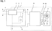
- FIG. 1 shows in the form of a schematic block diagram, an arrangement of components of a hybrid powertrain in a part of the electrical system 1 of a motor vehicle, in particular a commercial vehicle.
- the sub-board network 1 is connected in a conventional manner via a DC / DC converter 4 with a conventional electrical system 2, in which there are various consumers and a conventional battery.
- the sub-board network 1 can be operated, for example, with an increased low-voltage voltage in comparison to the main on-board network 2.
- an electrical energy store 5 in the form of an ultracap memory and an inverter (inverter) 10 and a switched reluctance machine 20 are arranged.
- the box marked with the reference numeral 3 is intended to denote no further component, but only the overall arrangement of DC-DC converter 4 and energy storage device 5.
- the reluctance machine 20 serves as a starter generator and can be operated both by motor and generator. During engine operation, the reluctance machine is supplied with energy from the energy store 5 via the inverter 10. In generator operation, the electrical energy generated by the reluctance machine can be stored by the energy store 5.
- the reluctance machine 20 is embodied in the exemplary embodiment as a three-phase reluctance motor 21. Each phase winding U, V, W of the reluctance motor 21 is guided with its positive and negative terminal 24 to the outside and connected to the inverter 10.
- the reluctance machine 20 further includes a rotor position sensor 22 and a temperature sensor 24. The measured values of the rotor position sensor 22 and the temperature sensor 24 are transmitted to the inverter 10 via signal lines 23.
- U H and U L denote the two potentials of the applied DC voltage.
- the supercap-memory 5 comprises, in a manner known per se, a control unit 5c with power electronics, which regulates the energy flows into and out of the supercap-memory cell module 5a.
- the supercap memory cell module can be disconnected from the onboard power supply 1 via an optional switch 5b.
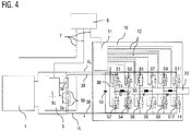
- the inverter 10 determines the power and mode of operation of the reluctance machine 20, and is driven by a vehicle controller 6 in accordance with the power demand to the reluctance machine 20.
- the vehicle controller 6 is connected via a control line 7 to a microcontroller 11 of the inverter and also via further control lines 7 with the DC-DC converter 4 and the control unit 5c of the energy store. 5
- the microcontroller 11 of the inverter drives the three phase windings U, V, and W of the reluctance machine by means of controllable semiconductor switches S in the form of circuit breakers.
- controllable semiconductor switches S in the form of circuit breakers.
- the in FIG. 2 illustrated embodiment of the inverter 10 twelve switches S (S1 to S12) on.
- An intermediate circuit capacitor 13 serves as a suppression capacity and is connected to the operating voltage between U H and U L.
- the DC link capacitor 13 can of course also be arranged outside of the inverter 10.
- Each of the parallel three phase branches of the inverter 10 for driving a respective phase winding U, V, or W comprises two high-side switches S1 and S3 or S5 and S7 or S9 and S11 and two low-side switches S2 and S4 or S6 and S8 or S10 and S12.
- an uncontrollable semiconductor switching element in the form of a freewheeling diode 14 is connected in anti-parallel.
- the switches S1 to S12 are designed as power MOSFETs and are controlled by the microcontroller 11 in each case via the control lines 12 at its gate, which represents the control input.
- the microcontroller 11 switches the semiconductor switches S1 and S4 to passage, so that a current flows through the phase winding U. If the semiconductor switches S1 and S4 are then switched off again by the microcontroller 11, a discharge current of the phase winding (not that of the energy store) flows through the freewheeling diodes 14 of the switches S2 and S3. An energization of the phase winding U in the reverse direction is also possible. For this purpose, the semiconductor switches S3 and S2 are switched to passage. The discharge current of the phase winding (not that of the energy store) then flows through the freewheeling diodes 14 of the switches S1 and S4.
- the energization of the phase windings V and W takes place analogously via the respective switches of the associated phase branches.
- the electric machine 20 is designed in the illustrated embodiment, three-phase, but may also have more than three phases, wherein for each phase in each case the phase strands, as described above, are provided in the inverter 10.
- phase branches of the inverter 10 of the type described above is known per se.
- FIG. 3 a flowchart of a method for discharging the energy storage to a stop state according to an embodiment of the invention described.
- step S1 the predetermined activation conditions for a discharge operation of the ultracap memory 5 are continuously monitored and their fulfillment is checked (step S2).
- two different activation conditions for activating the discharge process are predetermined, so that in two independent cases, a discharge process can be triggered.
- a first activation condition ensures that the Ultracap memory 5 is automatically discharged to a predetermined Abstelldepth if the vehicle is turned off and then if an actual charging voltage of the energy storage is greater than the predetermined target Abstellschreib.
- the vehicle controller 6 thus checks whether the vehicle has been turned off, ie, by evaluating suitable parameters, it is checked whether the driver has parked the vehicle and probably a renewed driving operation is not imminent. This can be z. B. can be detected by means of a lock of the vehicle. If a shutdown has been detected, the vehicle controller 6 further checks whether the actual charging voltage of the ultracap memory 5 is greater than the desired Abstellschreib.
- the ultra-cap memory 5 may have a memory module of 20 cells each with 2.7 V of maximum charging voltage. When parked, however, the cells should be charged with a maximum of 2 V in order to improve the service life.
- the current charging voltage of the ultracap memory 5 is continuously transmitted from the control unit 5c to the vehicle controller 6 and can then be compared with the target Abstellschreib.
- the first activation condition is met when the actual charging voltage of the parked vehicle is above the target Abstellbrief, so that in this case in step S3, one of the phase windings U, V or W is selected, which is energized for the discharge process.
- phase winding is determined in which the rotor is in a position with the smallest or minimum magnetic reluctance or maximum or maximum inductance.
- This phase winding generates when energized with the discharge current, the lowest effective torque, so that movement of the rotor is energized when energized the phase winding is avoided and this phase winding or inductance can be used as a discharge resistor without the reluctance machine generates an effective torque.
- step S4 the determined phase winding is used as a discharge resistor for the discharge current. If, for example, the phase U has been determined in step S3, the microcontroller 11 switches the semiconductor switches S1 and S4 to passage so that a discharge current flows through the phase winding U, which in FIG. 4 through line 30, which shows the discharge current. A discharge current could also flow in the opposite direction through the phase winding U. For this purpose, then the semiconductor switches S3 and S2 must be switched to passage. In contrast to the normal operation of the reluctance machine, the current supply generates no torque and no movement of the machine.
- the discharging process is terminated when the actual charging voltage has dropped to the desired Abstellbrief.
- the unloading process can also be started when a second activation condition is met.
- This second activation conditions initiates a complete discharge of the energy storage, if an error occurs in the energy storage, eg. As a failure of a cell of the energy storage, is diagnosed or performing service or maintenance is displayed, as already described above.
- the discharge process is again analogous to the steps S3 and S4.
Landscapes
- Engineering & Computer Science (AREA)
- Life Sciences & Earth Sciences (AREA)
- Sustainable Development (AREA)
- Sustainable Energy (AREA)
- Power Engineering (AREA)
- Transportation (AREA)
- Mechanical Engineering (AREA)
- Electric Propulsion And Braking For Vehicles (AREA)
- Control Of Electric Motors In General (AREA)
Applications Claiming Priority (1)
| Application Number | Priority Date | Filing Date | Title |
|---|---|---|---|
| DE102015004309.9A DE102015004309A1 (de) | 2015-04-01 | 2015-04-01 | Verfahren zum Entladen eines elektrischen Energiespeichers eies Kraftfahrzeugs |
Publications (2)
| Publication Number | Publication Date |
|---|---|
| EP3075593A1 true EP3075593A1 (fr) | 2016-10-05 |
| EP3075593B1 EP3075593B1 (fr) | 2023-01-04 |
Family
ID=55589637
Family Applications (1)
| Application Number | Title | Priority Date | Filing Date |
|---|---|---|---|
| EP16000668.0A Active EP3075593B1 (fr) | 2015-04-01 | 2016-03-18 | Procede de dechargement d'un accumulateur d'energie electrique de vehicule automobile |
Country Status (4)
| Country | Link |
|---|---|
| EP (1) | EP3075593B1 (fr) |
| DE (1) | DE102015004309A1 (fr) |
| HU (1) | HUE061243T2 (fr) |
| PL (1) | PL3075593T3 (fr) |
Cited By (1)
| Publication number | Priority date | Publication date | Assignee | Title |
|---|---|---|---|---|
| CN111731102A (zh) * | 2020-06-28 | 2020-10-02 | 德尔福科技(苏州)有限公司 | 一种基于直流电压反馈控制的电机绕组主动放电控制方法 |
Citations (5)
| Publication number | Priority date | Publication date | Assignee | Title |
|---|---|---|---|---|
| DE4235138A1 (de) * | 1992-10-19 | 1994-04-21 | Kiepe Bahn Elektrik Gmbh | Einrichtung zur Schutzentladung von Gleichspannungskondensatoren in Stromrichteranlagen |
| JPH0970196A (ja) * | 1995-08-31 | 1997-03-11 | Toyota Motor Corp | インバータ内部蓄電手段の放電装置 |
| US20040008530A1 (en) * | 2002-06-05 | 2004-01-15 | Kabushiki Kaisha Toshiba | Inverter control device and electric vehicle thereof |
| WO2008138864A1 (fr) * | 2007-05-14 | 2008-11-20 | Siemens Aktiengesellschaft | Procédé et dispositif de fonctionnement d'une unité de commande pour commander une machine électrique |
| EP2769868A2 (fr) * | 2013-02-25 | 2014-08-27 | Fairfield Manufacturing Company, Inc. | Système électrique hybride |
-
2015
- 2015-04-01 DE DE102015004309.9A patent/DE102015004309A1/de not_active Withdrawn
-
2016
- 2016-03-18 PL PL16000668.0T patent/PL3075593T3/pl unknown
- 2016-03-18 HU HUE16000668A patent/HUE061243T2/hu unknown
- 2016-03-18 EP EP16000668.0A patent/EP3075593B1/fr active Active
Patent Citations (5)
| Publication number | Priority date | Publication date | Assignee | Title |
|---|---|---|---|---|
| DE4235138A1 (de) * | 1992-10-19 | 1994-04-21 | Kiepe Bahn Elektrik Gmbh | Einrichtung zur Schutzentladung von Gleichspannungskondensatoren in Stromrichteranlagen |
| JPH0970196A (ja) * | 1995-08-31 | 1997-03-11 | Toyota Motor Corp | インバータ内部蓄電手段の放電装置 |
| US20040008530A1 (en) * | 2002-06-05 | 2004-01-15 | Kabushiki Kaisha Toshiba | Inverter control device and electric vehicle thereof |
| WO2008138864A1 (fr) * | 2007-05-14 | 2008-11-20 | Siemens Aktiengesellschaft | Procédé et dispositif de fonctionnement d'une unité de commande pour commander une machine électrique |
| EP2769868A2 (fr) * | 2013-02-25 | 2014-08-27 | Fairfield Manufacturing Company, Inc. | Système électrique hybride |
Cited By (1)
| Publication number | Priority date | Publication date | Assignee | Title |
|---|---|---|---|---|
| CN111731102A (zh) * | 2020-06-28 | 2020-10-02 | 德尔福科技(苏州)有限公司 | 一种基于直流电压反馈控制的电机绕组主动放电控制方法 |
Also Published As
| Publication number | Publication date |
|---|---|
| EP3075593B1 (fr) | 2023-01-04 |
| PL3075593T3 (pl) | 2023-03-06 |
| HUE061243T2 (hu) | 2023-06-28 |
| DE102015004309A1 (de) | 2016-10-06 |
Similar Documents
| Publication | Publication Date | Title |
|---|---|---|
| DE10050383B4 (de) | Hybridfahrzeug und Verfahren zur Erzeugung einer Antriebskraft eines Hybridfahrzeugs | |
| EP2588340B1 (fr) | Procédé pour faire fonctionner une machine électrique au moins triphasée faisant office de mécanisme d'entraînement dans un véhicule automobile et appareil de commande pour onduleur | |
| DE102014203030B4 (de) | Verfahren zum gesteuerten Verbinden mehrerer Bordnetzzweige eines Fahrzeugs, Steuereinheit zur Ausführung des Verfahrens sowie Fahrzeugbordnetz | |
| DE102010001250B4 (de) | Elektrisches Bordnetz sowie Verfahren zum Betreiben eines elektrischen Bordnetzes | |
| EP3083320B1 (fr) | Appareil et procede pour faire fonctionner une machine électrique | |
| EP2528766B1 (fr) | Système de batterie pour véhicules micro-hybrides à consommateurs de forte puissance | |
| WO2007085566A1 (fr) | Procédé pour couper une machine électrique en cas de défaillance | |
| EP3067240B1 (fr) | Procede d'alimentation en tension d'un reseau de bord d'un vehicule automobile | |
| DE102017207886A1 (de) | Steuereinheit und Verfahren zum Ansteuern einer Wechselrichterschaltung für einen Permanentmagnet-Synchronmotor | |
| WO2011009789A1 (fr) | Dispositif de commande pour une machine électrique, et procédé de mise en uvre du dispositif de commande | |
| WO2012048939A2 (fr) | Procédé de surveillance du mode de charge d'un accumulateur d'énergie dans un véhicule et système de charge servant à charger un accumulateur d'énergie dans un véhicule | |
| WO2013143847A2 (fr) | Système d'accumulation d'énergie équipé d'éléments refroidisseurs et procédé de refroidissement d'éléments accumulateurs d'énergie | |
| DE102017108396A1 (de) | Fehlerabschaltsteuerung einer elektrischen maschine in einem fahrzeug oder anderen gleichstromdrehmomentsystemen | |
| WO2012072311A1 (fr) | Procédé et dispositif pour faire fonctionner une machine électrique commandée par un onduleur en cas de perturbation | |
| DE102017206497B4 (de) | Ladevorrichtung und Verfahren zum Laden eines elektrischen Energiespeichers eines Fahrzeugs, sowie Kraftfahrzeug | |
| WO2015172924A1 (fr) | Dispositif et procédé pour charger deux accumulateurs d'énergie | |
| EP2528767B1 (fr) | Système de batterie pour véhicules micro-hybrides à consommateurs de forte puissance | |
| WO2018087073A1 (fr) | Réseau de bord de véhicule automobile pour un véhicule à propulsion électrique et procédé permettant de faire fonctionner un réseau de bord de véhicule automobile | |
| DE102022113800B4 (de) | Verfahren zum Betrieb einer elektrischen Maschine, insbesondere in einem Kraftfahrzeug, und Kraftfahrzeug | |
| EP2840253B1 (fr) | Réseau de bord pour un véhicule automobile et véhicule avec un tel réseau de bord | |
| DE102021129144B4 (de) | Verfahren zum Betreiben einer elektrischen Schaltungsanordnung, elektrische Schaltung und Kraftfahrzeug | |
| DE102013201909A1 (de) | Energiespeichereinrichtung und Verfahren zum Ansteuern einer Energiespeichereinrichtung bei einem Kommunikationsausfall | |
| EP3075593B1 (fr) | Procede de dechargement d'un accumulateur d'energie electrique de vehicule automobile | |
| EP2552727B1 (fr) | Onduleur pour une machine électrique et procédé pour faire fonctionner un onduleur pour une machine électrique | |
| DE112018002059T5 (de) | Rotierende-Elektrische-Maschinen-Steuerungsvorrichtung und Leistungsquellensystem |
Legal Events
| Date | Code | Title | Description |
|---|---|---|---|
| PUAI | Public reference made under article 153(3) epc to a published international application that has entered the european phase |
Free format text: ORIGINAL CODE: 0009012 |
|
| AK | Designated contracting states |
Kind code of ref document: A1 Designated state(s): AL AT BE BG CH CY CZ DE DK EE ES FI FR GB GR HR HU IE IS IT LI LT LU LV MC MK MT NL NO PL PT RO RS SE SI SK SM TR |
|
| AX | Request for extension of the european patent |
Extension state: BA ME |
|
| STAA | Information on the status of an ep patent application or granted ep patent |
Free format text: STATUS: REQUEST FOR EXAMINATION WAS MADE |
|
| 17P | Request for examination filed |
Effective date: 20170404 |
|
| RBV | Designated contracting states (corrected) |
Designated state(s): AL AT BE BG CH CY CZ DE DK EE ES FI FR GB GR HR HU IE IS IT LI LT LU LV MC MK MT NL NO PL PT RO RS SE SI SK SM TR |
|
| RAP1 | Party data changed (applicant data changed or rights of an application transferred) |
Owner name: MAN TRUCK & BUS SE |
|
| STAA | Information on the status of an ep patent application or granted ep patent |
Free format text: STATUS: EXAMINATION IS IN PROGRESS |
|
| 17Q | First examination report despatched |
Effective date: 20201001 |
|
| GRAP | Despatch of communication of intention to grant a patent |
Free format text: ORIGINAL CODE: EPIDOSNIGR1 |
|
| STAA | Information on the status of an ep patent application or granted ep patent |
Free format text: STATUS: GRANT OF PATENT IS INTENDED |
|
| INTG | Intention to grant announced |
Effective date: 20220310 |
|
| GRAJ | Information related to disapproval of communication of intention to grant by the applicant or resumption of examination proceedings by the epo deleted |
Free format text: ORIGINAL CODE: EPIDOSDIGR1 |
|
| STAA | Information on the status of an ep patent application or granted ep patent |
Free format text: STATUS: EXAMINATION IS IN PROGRESS |
|
| GRAS | Grant fee paid |
Free format text: ORIGINAL CODE: EPIDOSNIGR3 |
|
| STAA | Information on the status of an ep patent application or granted ep patent |
Free format text: STATUS: GRANT OF PATENT IS INTENDED |
|
| GRAP | Despatch of communication of intention to grant a patent |
Free format text: ORIGINAL CODE: EPIDOSNIGR1 |
|
| INTC | Intention to grant announced (deleted) | ||
| INTG | Intention to grant announced |
Effective date: 20220808 |
|
| GRAA | (expected) grant |
Free format text: ORIGINAL CODE: 0009210 |
|
| STAA | Information on the status of an ep patent application or granted ep patent |
Free format text: STATUS: THE PATENT HAS BEEN GRANTED |
|
| AK | Designated contracting states |
Kind code of ref document: B1 Designated state(s): AL AT BE BG CH CY CZ DE DK EE ES FI FR GB GR HR HU IE IS IT LI LT LU LV MC MK MT NL NO PL PT RO RS SE SI SK SM TR |
|
| REG | Reference to a national code |
Ref country code: GB Ref legal event code: FG4D Free format text: NOT ENGLISH |
|
| REG | Reference to a national code |
Ref country code: DE Ref legal event code: R096 Ref document number: 502016015515 Country of ref document: DE |
|
| REG | Reference to a national code |
Ref country code: CH Ref legal event code: EP |
|
| REG | Reference to a national code |
Ref country code: AT Ref legal event code: REF Ref document number: 1541703 Country of ref document: AT Kind code of ref document: T Effective date: 20230115 |
|
| REG | Reference to a national code |
Ref country code: IE Ref legal event code: FG4D Free format text: LANGUAGE OF EP DOCUMENT: GERMAN |
|
| REG | Reference to a national code |
Ref country code: NL Ref legal event code: FP |
|
| REG | Reference to a national code |
Ref country code: SE Ref legal event code: TRGR |
|
| REG | Reference to a national code |
Ref country code: LT Ref legal event code: MG9D |
|
| REG | Reference to a national code |
Ref country code: HU Ref legal event code: AG4A Ref document number: E061243 Country of ref document: HU |
|
| PG25 | Lapsed in a contracting state [announced via postgrant information from national office to epo] |
Ref country code: RS Free format text: LAPSE BECAUSE OF FAILURE TO SUBMIT A TRANSLATION OF THE DESCRIPTION OR TO PAY THE FEE WITHIN THE PRESCRIBED TIME-LIMIT Effective date: 20230104 Ref country code: PT Free format text: LAPSE BECAUSE OF FAILURE TO SUBMIT A TRANSLATION OF THE DESCRIPTION OR TO PAY THE FEE WITHIN THE PRESCRIBED TIME-LIMIT Effective date: 20230504 Ref country code: NO Free format text: LAPSE BECAUSE OF FAILURE TO SUBMIT A TRANSLATION OF THE DESCRIPTION OR TO PAY THE FEE WITHIN THE PRESCRIBED TIME-LIMIT Effective date: 20230404 Ref country code: LV Free format text: LAPSE BECAUSE OF FAILURE TO SUBMIT A TRANSLATION OF THE DESCRIPTION OR TO PAY THE FEE WITHIN THE PRESCRIBED TIME-LIMIT Effective date: 20230104 Ref country code: LT Free format text: LAPSE BECAUSE OF FAILURE TO SUBMIT A TRANSLATION OF THE DESCRIPTION OR TO PAY THE FEE WITHIN THE PRESCRIBED TIME-LIMIT Effective date: 20230104 Ref country code: HR Free format text: LAPSE BECAUSE OF FAILURE TO SUBMIT A TRANSLATION OF THE DESCRIPTION OR TO PAY THE FEE WITHIN THE PRESCRIBED TIME-LIMIT Effective date: 20230104 Ref country code: ES Free format text: LAPSE BECAUSE OF FAILURE TO SUBMIT A TRANSLATION OF THE DESCRIPTION OR TO PAY THE FEE WITHIN THE PRESCRIBED TIME-LIMIT Effective date: 20230104 |
|
| PG25 | Lapsed in a contracting state [announced via postgrant information from national office to epo] |
Ref country code: IS Free format text: LAPSE BECAUSE OF FAILURE TO SUBMIT A TRANSLATION OF THE DESCRIPTION OR TO PAY THE FEE WITHIN THE PRESCRIBED TIME-LIMIT Effective date: 20230504 Ref country code: GR Free format text: LAPSE BECAUSE OF FAILURE TO SUBMIT A TRANSLATION OF THE DESCRIPTION OR TO PAY THE FEE WITHIN THE PRESCRIBED TIME-LIMIT Effective date: 20230405 Ref country code: FI Free format text: LAPSE BECAUSE OF FAILURE TO SUBMIT A TRANSLATION OF THE DESCRIPTION OR TO PAY THE FEE WITHIN THE PRESCRIBED TIME-LIMIT Effective date: 20230104 |
|
| REG | Reference to a national code |
Ref country code: DE Ref legal event code: R097 Ref document number: 502016015515 Country of ref document: DE |
|
| PG25 | Lapsed in a contracting state [announced via postgrant information from national office to epo] |
Ref country code: SM Free format text: LAPSE BECAUSE OF FAILURE TO SUBMIT A TRANSLATION OF THE DESCRIPTION OR TO PAY THE FEE WITHIN THE PRESCRIBED TIME-LIMIT Effective date: 20230104 Ref country code: RO Free format text: LAPSE BECAUSE OF FAILURE TO SUBMIT A TRANSLATION OF THE DESCRIPTION OR TO PAY THE FEE WITHIN THE PRESCRIBED TIME-LIMIT Effective date: 20230104 Ref country code: MC Free format text: LAPSE BECAUSE OF FAILURE TO SUBMIT A TRANSLATION OF THE DESCRIPTION OR TO PAY THE FEE WITHIN THE PRESCRIBED TIME-LIMIT Effective date: 20230104 Ref country code: EE Free format text: LAPSE BECAUSE OF FAILURE TO SUBMIT A TRANSLATION OF THE DESCRIPTION OR TO PAY THE FEE WITHIN THE PRESCRIBED TIME-LIMIT Effective date: 20230104 Ref country code: DK Free format text: LAPSE BECAUSE OF FAILURE TO SUBMIT A TRANSLATION OF THE DESCRIPTION OR TO PAY THE FEE WITHIN THE PRESCRIBED TIME-LIMIT Effective date: 20230104 Ref country code: CZ Free format text: LAPSE BECAUSE OF FAILURE TO SUBMIT A TRANSLATION OF THE DESCRIPTION OR TO PAY THE FEE WITHIN THE PRESCRIBED TIME-LIMIT Effective date: 20230104 |
|
| REG | Reference to a national code |
Ref country code: CH Ref legal event code: PL |
|
| PLBE | No opposition filed within time limit |
Free format text: ORIGINAL CODE: 0009261 |
|
| STAA | Information on the status of an ep patent application or granted ep patent |
Free format text: STATUS: NO OPPOSITION FILED WITHIN TIME LIMIT |
|
| PG25 | Lapsed in a contracting state [announced via postgrant information from national office to epo] |
Ref country code: SK Free format text: LAPSE BECAUSE OF FAILURE TO SUBMIT A TRANSLATION OF THE DESCRIPTION OR TO PAY THE FEE WITHIN THE PRESCRIBED TIME-LIMIT Effective date: 20230104 |
|
| REG | Reference to a national code |
Ref country code: BE Ref legal event code: MM Effective date: 20230331 |
|
| 26N | No opposition filed |
Effective date: 20231005 |
|
| GBPC | Gb: european patent ceased through non-payment of renewal fee |
Effective date: 20230404 |
|
| PG25 | Lapsed in a contracting state [announced via postgrant information from national office to epo] |
Ref country code: LU Free format text: LAPSE BECAUSE OF NON-PAYMENT OF DUE FEES Effective date: 20230318 |
|
| REG | Reference to a national code |
Ref country code: IE Ref legal event code: MM4A |
|
| PG25 | Lapsed in a contracting state [announced via postgrant information from national office to epo] |
Ref country code: GB Free format text: LAPSE BECAUSE OF NON-PAYMENT OF DUE FEES Effective date: 20230404 |
|
| PG25 | Lapsed in a contracting state [announced via postgrant information from national office to epo] |
Ref country code: SI Free format text: LAPSE BECAUSE OF FAILURE TO SUBMIT A TRANSLATION OF THE DESCRIPTION OR TO PAY THE FEE WITHIN THE PRESCRIBED TIME-LIMIT Effective date: 20230104 Ref country code: LI Free format text: LAPSE BECAUSE OF NON-PAYMENT OF DUE FEES Effective date: 20230331 Ref country code: IE Free format text: LAPSE BECAUSE OF NON-PAYMENT OF DUE FEES Effective date: 20230318 Ref country code: GB Free format text: LAPSE BECAUSE OF NON-PAYMENT OF DUE FEES Effective date: 20230404 Ref country code: CH Free format text: LAPSE BECAUSE OF NON-PAYMENT OF DUE FEES Effective date: 20230331 |
|
| PG25 | Lapsed in a contracting state [announced via postgrant information from national office to epo] |
Ref country code: BE Free format text: LAPSE BECAUSE OF NON-PAYMENT OF DUE FEES Effective date: 20230331 |
|
| REG | Reference to a national code |
Ref country code: AT Ref legal event code: MM01 Ref document number: 1541703 Country of ref document: AT Kind code of ref document: T Effective date: 20230318 |
|
| PG25 | Lapsed in a contracting state [announced via postgrant information from national office to epo] |
Ref country code: AT Free format text: LAPSE BECAUSE OF NON-PAYMENT OF DUE FEES Effective date: 20230318 |
|
| PG25 | Lapsed in a contracting state [announced via postgrant information from national office to epo] |
Ref country code: AT Free format text: LAPSE BECAUSE OF NON-PAYMENT OF DUE FEES Effective date: 20230318 |
|
| PG25 | Lapsed in a contracting state [announced via postgrant information from national office to epo] |
Ref country code: BG Free format text: LAPSE BECAUSE OF FAILURE TO SUBMIT A TRANSLATION OF THE DESCRIPTION OR TO PAY THE FEE WITHIN THE PRESCRIBED TIME-LIMIT Effective date: 20230104 |
|
| PG25 | Lapsed in a contracting state [announced via postgrant information from national office to epo] |
Ref country code: BG Free format text: LAPSE BECAUSE OF FAILURE TO SUBMIT A TRANSLATION OF THE DESCRIPTION OR TO PAY THE FEE WITHIN THE PRESCRIBED TIME-LIMIT Effective date: 20230104 |
|
| PG25 | Lapsed in a contracting state [announced via postgrant information from national office to epo] |
Ref country code: CY Free format text: LAPSE BECAUSE OF FAILURE TO SUBMIT A TRANSLATION OF THE DESCRIPTION OR TO PAY THE FEE WITHIN THE PRESCRIBED TIME-LIMIT; INVALID AB INITIO Effective date: 20160318 |
|
| PGFP | Annual fee paid to national office [announced via postgrant information from national office to epo] |
Ref country code: SE Payment date: 20260323 Year of fee payment: 11 |
|
| PGFP | Annual fee paid to national office [announced via postgrant information from national office to epo] |
Ref country code: DE Payment date: 20260320 Year of fee payment: 11 |
|
| PGFP | Annual fee paid to national office [announced via postgrant information from national office to epo] |
Ref country code: IT Payment date: 20260320 Year of fee payment: 11 |
|
| PGFP | Annual fee paid to national office [announced via postgrant information from national office to epo] |
Ref country code: NL Payment date: 20260323 Year of fee payment: 11 Ref country code: HU Payment date: 20260309 Year of fee payment: 11 |
|
| PGFP | Annual fee paid to national office [announced via postgrant information from national office to epo] |
Ref country code: FR Payment date: 20260323 Year of fee payment: 11 |
|
| PGFP | Annual fee paid to national office [announced via postgrant information from national office to epo] |
Ref country code: TR Payment date: 20260306 Year of fee payment: 11 |
|
| PGFP | Annual fee paid to national office [announced via postgrant information from national office to epo] |
Ref country code: PL Payment date: 20260305 Year of fee payment: 11 |