EP3076020A1 - Pompe à eau électrique à écoulement variable régulé à ressort - Google Patents
Pompe à eau électrique à écoulement variable régulé à ressort Download PDFInfo
- Publication number
- EP3076020A1 EP3076020A1 EP16161763.4A EP16161763A EP3076020A1 EP 3076020 A1 EP3076020 A1 EP 3076020A1 EP 16161763 A EP16161763 A EP 16161763A EP 3076020 A1 EP3076020 A1 EP 3076020A1
- Authority
- EP
- European Patent Office
- Prior art keywords
- rotor unit
- electric water
- pump
- water pump
- impeller
- Prior art date
- Legal status (The legal status is an assumption and is not a legal conclusion. Google has not performed a legal analysis and makes no representation as to the accuracy of the status listed.)
- Granted
Links
Images



Classifications
-
- F—MECHANICAL ENGINEERING; LIGHTING; HEATING; WEAPONS; BLASTING
- F04—POSITIVE - DISPLACEMENT MACHINES FOR LIQUIDS; PUMPS FOR LIQUIDS OR ELASTIC FLUIDS
- F04D—NON-POSITIVE-DISPLACEMENT PUMPS
- F04D13/00—Pumping installations or systems
- F04D13/02—Units comprising pumps and their driving means
- F04D13/06—Units comprising pumps and their driving means the pump being electrically driven
- F04D13/0606—Canned motor pumps
-
- F—MECHANICAL ENGINEERING; LIGHTING; HEATING; WEAPONS; BLASTING
- F01—MACHINES OR ENGINES IN GENERAL; ENGINE PLANTS IN GENERAL; STEAM ENGINES
- F01P—COOLING OF MACHINES OR ENGINES IN GENERAL; COOLING OF INTERNAL-COMBUSTION ENGINES
- F01P3/00—Liquid cooling
- F01P3/20—Cooling circuits not specific to a single part of engine or machine
-
- F—MECHANICAL ENGINEERING; LIGHTING; HEATING; WEAPONS; BLASTING
- F01—MACHINES OR ENGINES IN GENERAL; ENGINE PLANTS IN GENERAL; STEAM ENGINES
- F01P—COOLING OF MACHINES OR ENGINES IN GENERAL; COOLING OF INTERNAL-COMBUSTION ENGINES
- F01P7/00—Controlling of coolant flow
- F01P7/14—Controlling of coolant flow the coolant being liquid
- F01P7/16—Controlling of coolant flow the coolant being liquid by thermostatic control
- F01P7/164—Controlling of coolant flow the coolant being liquid by thermostatic control by varying pump speed
-
- F—MECHANICAL ENGINEERING; LIGHTING; HEATING; WEAPONS; BLASTING
- F04—POSITIVE - DISPLACEMENT MACHINES FOR LIQUIDS; PUMPS FOR LIQUIDS OR ELASTIC FLUIDS
- F04D—NON-POSITIVE-DISPLACEMENT PUMPS
- F04D13/00—Pumping installations or systems
- F04D13/02—Units comprising pumps and their driving means
- F04D13/06—Units comprising pumps and their driving means the pump being electrically driven
-
- F—MECHANICAL ENGINEERING; LIGHTING; HEATING; WEAPONS; BLASTING
- F04—POSITIVE - DISPLACEMENT MACHINES FOR LIQUIDS; PUMPS FOR LIQUIDS OR ELASTIC FLUIDS
- F04D—NON-POSITIVE-DISPLACEMENT PUMPS
- F04D13/00—Pumping installations or systems
- F04D13/02—Units comprising pumps and their driving means
- F04D13/06—Units comprising pumps and their driving means the pump being electrically driven
- F04D13/0686—Mechanical details of the pump control unit
-
- F—MECHANICAL ENGINEERING; LIGHTING; HEATING; WEAPONS; BLASTING
- F04—POSITIVE - DISPLACEMENT MACHINES FOR LIQUIDS; PUMPS FOR LIQUIDS OR ELASTIC FLUIDS
- F04D—NON-POSITIVE-DISPLACEMENT PUMPS
- F04D15/00—Control, e.g. regulation, of pumps, pumping installations or systems
- F04D15/0027—Varying behaviour or the very pump
-
- F—MECHANICAL ENGINEERING; LIGHTING; HEATING; WEAPONS; BLASTING
- F04—POSITIVE - DISPLACEMENT MACHINES FOR LIQUIDS; PUMPS FOR LIQUIDS OR ELASTIC FLUIDS
- F04D—NON-POSITIVE-DISPLACEMENT PUMPS
- F04D15/00—Control, e.g. regulation, of pumps, pumping installations or systems
- F04D15/0027—Varying behaviour or the very pump
- F04D15/0033—By-passing by increasing clearance between impeller and its casing
-
- F—MECHANICAL ENGINEERING; LIGHTING; HEATING; WEAPONS; BLASTING
- F04—POSITIVE - DISPLACEMENT MACHINES FOR LIQUIDS; PUMPS FOR LIQUIDS OR ELASTIC FLUIDS
- F04D—NON-POSITIVE-DISPLACEMENT PUMPS
- F04D15/00—Control, e.g. regulation, of pumps, pumping installations or systems
- F04D15/0027—Varying behaviour or the very pump
- F04D15/0038—Varying behaviour or the very pump by varying the effective cross-sectional area of flow through the rotor
-
- F—MECHANICAL ENGINEERING; LIGHTING; HEATING; WEAPONS; BLASTING
- F04—POSITIVE - DISPLACEMENT MACHINES FOR LIQUIDS; PUMPS FOR LIQUIDS OR ELASTIC FLUIDS
- F04D—NON-POSITIVE-DISPLACEMENT PUMPS
- F04D29/00—Details, component parts, or accessories
- F04D29/04—Shafts or bearings, or assemblies thereof
- F04D29/042—Axially shiftable rotors
-
- F—MECHANICAL ENGINEERING; LIGHTING; HEATING; WEAPONS; BLASTING
- F04—POSITIVE - DISPLACEMENT MACHINES FOR LIQUIDS; PUMPS FOR LIQUIDS OR ELASTIC FLUIDS
- F04D—NON-POSITIVE-DISPLACEMENT PUMPS
- F04D29/00—Details, component parts, or accessories
- F04D29/18—Rotors
- F04D29/22—Rotors specially for centrifugal pumps
- F04D29/2261—Rotors specially for centrifugal pumps with special measures
-
- F—MECHANICAL ENGINEERING; LIGHTING; HEATING; WEAPONS; BLASTING
- F04—POSITIVE - DISPLACEMENT MACHINES FOR LIQUIDS; PUMPS FOR LIQUIDS OR ELASTIC FLUIDS
- F04D—NON-POSITIVE-DISPLACEMENT PUMPS
- F04D29/00—Details, component parts, or accessories
- F04D29/40—Casings; Connections of working fluid
- F04D29/42—Casings; Connections of working fluid for radial or helico-centrifugal pumps
- F04D29/426—Casings; Connections of working fluid for radial or helico-centrifugal pumps especially adapted for liquid pumps
-
- F—MECHANICAL ENGINEERING; LIGHTING; HEATING; WEAPONS; BLASTING
- F01—MACHINES OR ENGINES IN GENERAL; ENGINE PLANTS IN GENERAL; STEAM ENGINES
- F01P—COOLING OF MACHINES OR ENGINES IN GENERAL; COOLING OF INTERNAL-COMBUSTION ENGINES
- F01P3/00—Liquid cooling
- F01P2003/001—Cooling liquid
-
- F—MECHANICAL ENGINEERING; LIGHTING; HEATING; WEAPONS; BLASTING
- F01—MACHINES OR ENGINES IN GENERAL; ENGINE PLANTS IN GENERAL; STEAM ENGINES
- F01P—COOLING OF MACHINES OR ENGINES IN GENERAL; COOLING OF INTERNAL-COMBUSTION ENGINES
- F01P2050/00—Applications
- F01P2050/22—Motor-cars
-
- F—MECHANICAL ENGINEERING; LIGHTING; HEATING; WEAPONS; BLASTING
- F05—INDEXING SCHEMES RELATING TO ENGINES OR PUMPS IN VARIOUS SUBCLASSES OF CLASSES F01-F04
- F05D—INDEXING SCHEME FOR ASPECTS RELATING TO NON-POSITIVE-DISPLACEMENT MACHINES OR ENGINES, GAS-TURBINES OR JET-PROPULSION PLANTS
- F05D2270/00—Control
- F05D2270/40—Type of control system
- F05D2270/42—Type of control system passive or reactive, e.g. using large wind vanes
Definitions
- the present disclosure relates generally to water pumps for motor vehicles. More specifically, the present disclosure relates to a variable flow electric water pump equipped with an axially-moveable rotor/impeller assembly.
- water pumps are typically used in motor vehicles as part of a thermal management system for pumping a liquid coolant to facilitate heat transfer between the coolant and the internal combustion engine during vehicle warm-up and operation.
- a centrifugal water pump having a rotary pump member, such as an impeller is configured to draw the coolant into an axial inlet and discharge the coolant through a radial discharge outlet.
- the impeller is fixed to an impeller shaft that is rotatably driven (via an accessory drive system) by the crankshaft of the engine.
- the impeller speed is directly proportional to the engine speed.
- it is known to permit limited axial displacement of the impeller within the pump chamber.
- U.S. Patent No. 7,789,049 discloses a water pump having an axially-moveable impeller that is spline mounted to the engine-driven shaft, and an electromagnetic actuator operable to control axial movement of the impeller between extended and retracted positions along the shaft so as to variably regulate the fluid flow characteristic between the fluid inlet and the discharge outlet.
- U.S. Patent No. 5,800,120 discloses a water pump having a shaft-driven impeller equipped with axially-moveable blades, the position of which is controlled via a hydraulic actuator.
- electric water pumps include an electric motor having a stationary stator and a rotor that is drivingly coupled to the impeller.
- Examples of electric water pumps are disclosed in commonly-owned U.S. Publication No. US2013/0259720 titled “Electric Water Pump With Stator Cooling” and U.S. Publication No. US2014/0017073 titled “Submerged Rotor Electric Water Pump with Structural Wetsleeve", the entire disclosures of which are incorporated herein by reference.
- the rotor/impeller assembly is located in a low flow position relative to the stator assembly when rotated at low rotor speeds and in a high flow position relative to the stator assembly when rotated at high rotor speeds.
- the rotor/impeller assembly is normally biased toward its low flow position by a mechanical biasing arrangement disposed between the rotor unit and a stationary member within a pump housing. Movement of the rotor/impeller assembly from its low flow position toward its high flow position is a result of a pressure differential ( ⁇ P) generated between upper (i.e. outer) and lower (i.e. inner) portions of the impeller and which is a function of the rotary speed of the rotor/impeller assembly.
- ⁇ P pressure differential
- the rotor/impeller assembly is normally located in its low flow position by a magnetic biasing arrangement provided by an axially-offset magnetic field between the stator assembly and the rotor unit that is established by rotor magnets having an increased length in the direction of the impeller so as to provide a centering relationship with the stator assembly during low speed operation.
- the present disclosure is directed to a variable flow electric water pump for use in an engine coolant system of a motor vehicle comprising: a pump housing defining a fluid chamber and a motor chamber, the fluid chamber including a fluid inlet and a discharge outlet for providing a flow of a coolant through the fluid chamber; an electric motor disposed in the motor chamber and including a stationary stator assembly and a rotor unit having a rotor shaft supported for rotation about a longitudinal axis and at least partially extending into the fluid chamber; an impeller fixed for rotation with the rotor shaft and disposed within the fluid chamber and being operable to pump the coolant from the fluid inlet to the discharge outlet; and a biasing arrangement operable for normally locating the rotor unit in a first position axially offset relative to the stator assembly for locating the impeller in a retracted position within the fluid chamber so as to provide a low flow characteristic between the fluid inlet and the discharge outlet when the impeller is rotatable driven by the rotor shaft at a low impeller speed
- variable flow electric water pump of the present disclosure is further operable when the impeller is rotatably driven at a higher impeller speed to forcibly move the impeller to an extended position within the fluid chamber, in opposition to the preload exerted by biasing arrangement, for causing the rotor unit to be located in a second position axially aligned with the stator assembly.
- the variable flow electric water pump of the present disclosure can be equipped with a mechanical biasing arrangement configured to normally exert a biasing force on the rotor unit selected to bias the rotor unit toward its first position.
- the mechanical biasing arrangement can include a mechanical biasing member, such as one or more spring members, disposed between an upper portion of the rotor unit and a stationary member or portion of the pump housing.
- variable flow electric water pump of the present disclosure can optionally be equipped with a magnetic biasing arrangement configured to normally locate the rotor unit in its first position.
- variable flow electric water pump of the present disclosure can further include an interface formed in the pump housing between the fluid inlet and the discharge outlet defining a flange surface.
- the impeller can be configured to include an outer rim surfaced aligned with the flange surface such that a first larger clearance gap is established therebetween when the impeller is located in its retracted position.
- the first larger clearance gap functions to establish a low flow characteristic when the impeller is driven at the low impeller speeds by the electric motor.
- a second smaller clearance gap is established when the impeller is located in its extended position so as to create a high flow characteristic when the impeller is driven by the electric motor at the high impeller speeds.
- the present disclosure relates to an electric pump and, more particularly, to an electric water pump of the type applicable and well-suited for use and installation in motor vehicles for pumping a liquid coolant through an engine cooling system.
- an electric pump and, more particularly, to an electric water pump of the type applicable and well-suited for use and installation in motor vehicles for pumping a liquid coolant through an engine cooling system.
- teachings provided herein are considered to be adaptable to any other electric pump required to move a medium (i.e. air, water, coolant, oil, etc.) within a pumping system requiring a variable flow capability.
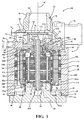
- Pump 10 generally includes a pump housing 12, an electric motor 14, and a pump unit 16.
- Pump housing 12 is shown in this non-limiting example to include a cylindrical outer housing 18, a first or bottom cap 20, and a second or top cap 22.
- Outer housing 18 is generally cup-shaped and includes an open end section 24 to which bottom cap 20 is secured, and an end plate section 26 to which top cap 22 is secured.
- End plate section 26 of outer housing 18 is formed to define a raised annular rim 28 extending from a planar mounting surface 30.
- a central pump pocket 32 is formed in rim 28 and is aligned on the longitudinal axis "A" of pump 10.
- a pair of internal annular bosses 34 and 36 also extend from end plate section 26 of outer housing 18 and are aligned with the longitudinal axis.
- a thorough bore 38 extends between pump pocket 32 and a bearing pocket 40 associated with annular boss 34.
- Bottom cap 20 is configured, in this non-limiting example, to include an annular rim 44 extending from a planar mounting surface 46, and an elongated cylindrical hub 48, both of which are concentric with the longitudinal axis.
- End section 24 of outer housing 18 includes an inner diameter wall surface 50 configured to be pressed against an outer diameter surface 52 of annular rim 44.
- End section 24 also includes a planar end surface 54 configured to engage mounting surface 46 on bottom cap 20. While not specifically shown, a suitable fastening arrangement is provided to secure bottom cap 20 to outer housing 18 so as to define an internal motor chamber 56.
- a blind bore 58 is formed in hub 48 and further defines a bearing pocket 60.
- Top cap 22 is shown, in this non-limiting example, configured to include an axially-extending tubular section 64 defining a fluid inlet 66, a radially-extending tubular section 68 defining a fluid discharge outlet 70, and a volute section 72 defining an impeller cavity 74 in fluid communication with fluid inlet 66 and discharge outlet 70.
- An interface 76 is formed in top cap 22 between fluid inlet 66 and impeller cavity 74 and includes a first flange surface 78 and a second flange surface 80.
- Top cap 22 includes a stepped flange section 82 configured to enclose a portion of raised rim 28 on end plate section 26 of outer housing 18.
- Top cap 22 also includes a planar inner mounting surface 84 configured to engage outer mounting surface 30 on outer housing 18. Suitable fasteners, such as a plurality of bolts 86, are provided for securely connecting top cap 22 to outer housing 18.
- electric motor 14 is generally shown, in this non-limiting example, to include a stator assembly 90, a rotor unit 92, and a sleeve 94.
- Sleeve 94 has a first end section 96 engaging end plate section 26 of outer housing 18, a second end section 98 surrounding a portion of hub 48 on bottom cap 20, and an elongated intermediate sleeve section 100 therebetween.
- An O-ring seal 102 is provided between annular rim 36 of end plate section 26 and first end section 96 of sleeve 94.
- Sleeve 94 is configured to delineate motor chamber 56 into a toroidal stator cavity 56A and a cylindrical rotor cavity 56B.
- Stator assembly 90 is located within stator cavity 56A and is configured to be non-moveable (i.e. stationary) therein.
- Rotor unit 92 is located within rotor cavity 56B and is configured to be both rotatable and axially moveable therein, as will be detailed hereinafter with greater specificity.
- Stator assembly 90 includes, in this non-limiting example, a coil winding 106 and a plurality or stack of plates 108 retained on a stator cage 110.
- Stator cage 110 in non-moveably mounted to outer housing 18 and/or sleeve 94 within stator cavity 56A.
- Rotor unit 92 is shown, in this non-limiting example, to include a rotor shaft 114 and a plurality of circumferentially-aligned permanent magnets 116 retained by or encapsulated in a rotor shell 118.
- An annular magnetic air gap 120 is established between intermediate sleeve segment 100 of sleeve 94 and rotor unit 92.
- the components of rotor unit 92 are fixed to rotor shaft 114 for common rotation about the longitudinal axis.
- a first or lower end portion 114A of rotor shaft 114 is disposed in blind bore 58 formed in bottom cap 20 and is supported for rotary and axial movement therein by a first or lower guide bushing 122 retained in bearing pocket 60.
- a second or upper end portion 114B of rotor shaft 114 extends through throughbore 38 and into impeller cavity 74. End portion 114B of rotor shaft 114 is supported for rotary and axial movement by a second or upper guide bushing 124 retained in bearing pocket 40 formed in annular boss 34.
- Pump unit 16 is shown, in this non-limiting example, to include a rotary pump member, such as an impeller 126, that is rigidly fixed to second end portion 114B of rotor shaft 114 for rotation within pump pocket 32.
- Impeller 126 is configured to include a central hub segment 128, a first or lower rim segment 130 extending radially from hub segment 128, a second or upper rim segment 132, and a plurality of contoured impeller blades 134 extending between lower rim segment 130 and upper rim segment 132.
- the actual number of impeller blades 134 and their particular contoured configuration i.e. profile, shape, thickness, etc.
- Upper rim segment 132 is configured to define a first rim surface 136 that is generally aligned with first flange surface 78 of volute interface 76, and define a second rim surface 138 that is generally aligned with second flange surface 80.
- a rotor/impeller assembly 150 (comprised of rotor unit 92, rotor shaft 114 and impeller 126) is moveable axially with respect to stator assembly 90 and inlet/volute interface 76 to provide a means for varying the flow characteristics of pump 10.
- FIGS. 1 and 2 further illustrate pump 10 to include a mechanical biasing arrangement 152 acting between rotor unit 92 and a stationary component or portion of pump housing 12.
- mechanical biasing arrangement 152 is shown, in the non-limiting example, to include a thrust washer 154 fixed to annular boss 34 (or abutting guide bushing 124) and a biasing member 156 acting between thrust washer 154 and an upper portion of rotor unit 92.
- biasing member 156 is a helical coil spring surrounding rotor shaft 114 and configured to apply a predefined spring load (i.e. "preload") on rotor unit 92 for normally biasing rotor unit 92 toward a first position within rotor cavity 56B, as shown in FIG. 1 .
- preload a predefined spring load
- rotor unit 92 is axially offset relative to stator assembly 90. Since impeller 126 is fixed via rotor shaft 114 to rotor unit 92, impeller 126 is located in a "retracted” position when rotor unit 92 is located in its first position.
- rotor/impeller assembly 150 is defined to be located in a "low flow” position within pump 10.
- a small clearance "X 1 " is established between a lower surface 140 of impeller hub 128 and a bottom surface 142 of impeller pocket 32.
- a large clearance "Y 1 " is established between corresponding interface surfaces 78, 80 and impeller rim surfaces 136, 138.
- the preload provided by biasing member 156 is selected to establish this offset relationship shown in FIG. 1 between stator assembly 90 and rotor unit 92 when the rotor shaft speeds are low so as to increase the clearance gap "Y" between impeller 126 and volute interface 76 to intentionally provide decreased pump efficiency and reduced flow.
- FIG. 2 illustrates pump 10 when rotor shaft 114 is driven at a higher rotary speed.
- impeller 126 when impeller 126 is rotated at higher speeds, a fluid pressure differential across impellor 126 acts to compress biasing member 156 which permits axial movement of rotor/impeller assembly 150 to a "high-flow" position ( FIG. 2 ).
- rotor/impeller assembly 150 With rotor/impeller assembly 150 located in its high flow position, rotor unit 92 is located in a second position relative to stator assembly 90 and impeller 126 is located in an "extended" position relative to volute interface 76.
- rotor unit 92 In its second position, rotor unit 92 is axially aligned with stator assembly 90 such that a large clearance "X 2 " is established between lower surface 140 of impeller hub 128 and bottom surface 142 of impeller pocket 32 while, concomitantly, a small clearance "Y 2 " is established between corresponding interface surfaces 78, 80 and impeller rim surfaces 136, 138.
- the counterforce generated to oppose and overcome the preload of biasing member 156 is a result of the pressure differential ( ⁇ P) generated when impeller 126 is rotated at higher speed.
- FIG. 3 provides a graphical illustration of the flow vs speed characteristics for a conventional electric water pump with a fixed rotor/impeller assembly (see line 160) in comparison to pump 10 of the present disclosure (see line 162). What is evident is that the reduced efficiency provided by spring-biasing rotary/impeller assembly 150 to its low flow position ( FIG. 1 ) results in reduced flow rates (LPM) at lower pump speeds.
- LPM reduced flow rates
- the illustration further illustrates that upon movement of rotor/impeller assembly 150 to its high flow position ( FIG. 2 ), the flow vs. speed characteristics of pump 10 tend to align with those of the conventional pump, identified in this non-limiting example as point "P".
- the present disclosure provides a unique and non-obvious variant of an electric water pump 10 that is configured to generate lower flow at low rotor speeds as well as generate high flow at higher rotor speeds. It is contemplated that the preload applied by biasing member 156 to rotor unit 92 can be calibrated based on pump speed so as to maintain rotor/impeller assembly 150 in its low flow position until increased pumping efficiency is required.
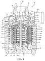
- pump 10' does not rely on spring-biasing arrangement 152 to provide axial movement of rotor/impeller assembly 150', but rather utilizes a magnetic biasing arrangement 152' provided by an axially-offset magnetic field arrangement between rotor unit 92' and stator assembly 90.
- rotor unit 92' is shown equipped with a plurality of elongated magnets 116' having extended end segments 116A extending axially outwardly from the top portion of rotor unit 92'.
- stator assembly 90 As shown in FIG. 4 , so as to locate rotor/impeller assembly 150' in the low flow position establishing clearance X 1 , and Y 1 , similar to those clearances associated with pump 10 of FIG. 1 .
- rotor unit 92' is located in its first position relative to stator assembly 90 and impeller 126 is located in its retracted position relative to volute interface 76 when rotor/impeller assembly 150 is in its low flow position.
- This "self-centering" action at low rotor speeds is caused by the centering behavior of the magnetic flux associated with the generated magnetic field.
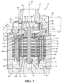
- FIG. 5 illustrates pump 10' when rotor unit 92' is driven at a higher speed which causes the pressure differential ( ⁇ P) across impeller 126 to forcibly move rotor/impeller assembly 150' in an upward direction to its second or extended position, thereby establishing clearances X 2 , Y 2 similar to pump 10 of FIG 2 .
- rotor unit 92' is located in its second position relative to stator assembly 90 while impeller 126 is located in its extended position relative to volute interface 76.
- pump 10' provides a magnetic biasing arrangement as an option to the mechanical biasing arrangement associated with pump 10.
- Line “B” in FIG. 5 identifies the stator's center magnetic field aligned with the rotor's center magnetic field.
- the clearance "D” in FIG. 4 identifies an example amount of magnetic offset between the rotor's center magnetic field and the stator's center magnetic field.
- pump 10 was illustrated to include a helical coil spring as biasing member 156
- biasing member 156 those skilled in the art recognize that other types and/or combinations of biasing devices configured to normally bias rotor/impeller assembly 150 to its low flow position during low speed/low flow operation can be employed.
- a combination of the spring-biased arrangement 152 of FIGS. 1 and 2 can be integrated with the magnetic field arrangement 152' of FIGS. 4 and 5 to provide a hybrid variant of yet another embodiment of an electric water pump that is within the anticipated scope of this disclosure.
- controller device which functions to control operation of electric motor 12 and the rotational speed of impeller 126.
- the controller device may include an electronic circuit board (ECB) electrically connected to stator assembly 90 and which can be mounted within pump housing 18.
- EEB electronic circuit board
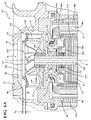
- FIGS. 6A and 6B another alternative embodiment of an electric water pump 10" is shown which is generally similar to electric water pump 10 of FIGS. 1 and 2 with the exception that impeller 126" now includes a molded-in sleeve 170 within which end portion 114B of rotor shaft 114 is pressed into.
- mechanical biasing arrangement 152" now includes a plurality of stacked wave or spring washers 172, such as Belleville washers, surrounding rotor shaft 114 and being disposed between a top portion of rotor unit 92 and thrust washer 154.
- the structure and function of water pump 10" is generally similar to that of water pump 10.
Landscapes
- Engineering & Computer Science (AREA)
- Mechanical Engineering (AREA)
- General Engineering & Computer Science (AREA)
- Chemical & Material Sciences (AREA)
- Combustion & Propulsion (AREA)
- Structures Of Non-Positive Displacement Pumps (AREA)
Applications Claiming Priority (1)
| Application Number | Priority Date | Filing Date | Title |
|---|---|---|---|
| US201562140854P | 2015-03-31 | 2015-03-31 |
Publications (2)
| Publication Number | Publication Date |
|---|---|
| EP3076020A1 true EP3076020A1 (fr) | 2016-10-05 |
| EP3076020B1 EP3076020B1 (fr) | 2020-12-30 |
Family
ID=55588147
Family Applications (1)
| Application Number | Title | Priority Date | Filing Date |
|---|---|---|---|
| EP16161763.4A Active EP3076020B1 (fr) | 2015-03-31 | 2016-03-22 | Pompe à eau électrique à écoulement variable régulé à ressort |
Country Status (3)
| Country | Link |
|---|---|
| US (2) | US20160290340A1 (fr) |
| EP (1) | EP3076020B1 (fr) |
| CN (1) | CN106015021B (fr) |
Cited By (2)
| Publication number | Priority date | Publication date | Assignee | Title |
|---|---|---|---|---|
| WO2019210955A1 (fr) | 2018-05-03 | 2019-11-07 | Pierburg Pump Technology Gmbh | Moteur électrique |
| CN113982737A (zh) * | 2021-11-17 | 2022-01-28 | 李燕莉 | 一种汽车水泵 |
Families Citing this family (12)
| Publication number | Priority date | Publication date | Assignee | Title |
|---|---|---|---|---|
| KR101812033B1 (ko) * | 2016-11-03 | 2018-01-25 | 뉴모텍(주) | 전이상태에서 발생하는 소음을 방지할 수 있는 온수 순환 펌프 |
| KR101874493B1 (ko) * | 2017-03-17 | 2018-07-05 | 명화공업주식회사 | 워터펌프 |
| JP6572267B2 (ja) * | 2017-07-24 | 2019-09-04 | ファナック株式会社 | 制限移動可能な軸を備えるモータ及び工作機械 |
| US10426145B2 (en) * | 2018-01-02 | 2019-10-01 | Shenzhen Honya Aquarium Equipments Manufacturer Co., Ltd. | Wave-making pump with novel directional structure |
| CN109162929A (zh) * | 2018-07-27 | 2019-01-08 | 湖南山水节能科技股份有限公司 | 离心泵 |
| US11459958B2 (en) * | 2019-03-22 | 2022-10-04 | Pratt & Whitney Canada Corp. | Rotodynamic pump having a body defining a body cavity with a first and second housing portion defining a portion of an impeller cavity and disposed within the body cavity wherein the body cavity extends at least in part around the second housing portion and the housing portions defining an impeller clearance |
| EP4140021A1 (fr) * | 2020-04-22 | 2023-03-01 | Stanadyne LLC | Actionneur et soupape de recirculation des gaz d'échappement (rge) compacte |
| DE102021207404A1 (de) * | 2021-07-13 | 2023-01-19 | Robert Bosch Gesellschaft mit beschränkter Haftung | Pumpenvorrichtung, insbesondere Magnetkupplungspumpenvorrichtung |
| CN114001036B (zh) * | 2021-10-25 | 2022-09-16 | 华中科技大学 | 一种微型水力悬浮机械泵及其装配方法 |
| US12104618B2 (en) | 2022-10-31 | 2024-10-01 | Hewlett Packard Enterprise Development Lp | Axial pump with adjustable impeller |
| DE102024136044B3 (de) | 2024-12-04 | 2026-04-23 | Schaeffler Technologies AG & Co. KG | Flüssigkeitsfördervorrichtung, Sensorreinigungsvorrichtung und Fahrzeug |
| US12474093B1 (en) * | 2025-05-23 | 2025-11-18 | Sencera Energy, Inc. | Stirling device |
Citations (6)
| Publication number | Priority date | Publication date | Assignee | Title |
|---|---|---|---|---|
| DE2510787A1 (de) * | 1975-03-08 | 1976-09-16 | Vaillant Joh Kg | Pumpe |
| US5800120A (en) | 1995-11-07 | 1998-09-01 | A. W. Chesterton Co. | Pump impeller with adjustable blades |
| US7789049B2 (en) | 2008-07-14 | 2010-09-07 | Honda Motor Co., Ltd. | Variable capacity water pump via electromagnetic control |
| US20130259720A1 (en) | 2010-08-25 | 2013-10-03 | Kyle D. Mills | Electric Water Pump With Stator Cooling |
| US20140017073A1 (en) | 2012-07-16 | 2014-01-16 | Magna Powertrain Of America, Inc. | Submerged rotor electric water pump with structural wetsleeve |
| EP2818725A1 (fr) * | 2013-06-27 | 2014-12-31 | Grundfos Holding A/S | Pompe centrifuge avec roue à aubes déplaçable axialement et obturable |
Family Cites Families (11)
| Publication number | Priority date | Publication date | Assignee | Title |
|---|---|---|---|---|
| DE1634729U (de) | 1950-02-10 | 1952-02-21 | Daimler Benz Ag | Drallblende fuer ladegeblaese von brennkaftmaschinen, insbesondere von fahrzeugmotoren. |
| US3918831A (en) | 1974-02-08 | 1975-11-11 | Chandler Evans Inc | Centrifugal pump with variable impeller |
| JPS62228699A (ja) * | 1986-03-31 | 1987-10-07 | Aisin Seiki Co Ltd | ウオ−タポンプ |
| US4828454A (en) | 1986-06-06 | 1989-05-09 | The United States Of America As Represented By The Secretary Of The Navy | Variable capacity centrifugal pump |
| DE102005056199A1 (de) * | 2005-11-25 | 2006-10-12 | Audi Ag | Pumpe für ein flüssiges Medium, insbesondere Kühlmittelpumpe, sowie Stellelement für eine solche Pumpe |
| WO2011069109A2 (fr) * | 2009-12-03 | 2011-06-09 | Richard Wampler | Cœur artificiel total |
| CN201723528U (zh) * | 2010-04-22 | 2011-01-26 | 浙江新时空水务有限公司 | 一种液体余压能量回收器 |
| US8888931B2 (en) * | 2010-12-14 | 2014-11-18 | General Electric Company | Dishwasher pump inlet macerator system |
| KR101874070B1 (ko) * | 2010-12-16 | 2018-07-03 | 바우뮐러 뉘른베르크 게엠베하 | 전기기기, 특히 펌프장치의 전기기기 |
| DE102014212022B4 (de) * | 2013-07-08 | 2016-06-09 | Magna Powertrain Bad Homburg GmbH | Pumpe |
| CN104421166A (zh) * | 2013-08-30 | 2015-03-18 | 刘讯岐 | 超高效液冷电机泵 |
-
2016
- 2016-03-22 EP EP16161763.4A patent/EP3076020B1/fr active Active
- 2016-03-24 US US15/079,123 patent/US20160290340A1/en not_active Abandoned
- 2016-03-29 CN CN201610187002.5A patent/CN106015021B/zh active Active
-
2019
- 2019-01-18 US US16/251,444 patent/US10760577B2/en active Active
Patent Citations (6)
| Publication number | Priority date | Publication date | Assignee | Title |
|---|---|---|---|---|
| DE2510787A1 (de) * | 1975-03-08 | 1976-09-16 | Vaillant Joh Kg | Pumpe |
| US5800120A (en) | 1995-11-07 | 1998-09-01 | A. W. Chesterton Co. | Pump impeller with adjustable blades |
| US7789049B2 (en) | 2008-07-14 | 2010-09-07 | Honda Motor Co., Ltd. | Variable capacity water pump via electromagnetic control |
| US20130259720A1 (en) | 2010-08-25 | 2013-10-03 | Kyle D. Mills | Electric Water Pump With Stator Cooling |
| US20140017073A1 (en) | 2012-07-16 | 2014-01-16 | Magna Powertrain Of America, Inc. | Submerged rotor electric water pump with structural wetsleeve |
| EP2818725A1 (fr) * | 2013-06-27 | 2014-12-31 | Grundfos Holding A/S | Pompe centrifuge avec roue à aubes déplaçable axialement et obturable |
Cited By (2)
| Publication number | Priority date | Publication date | Assignee | Title |
|---|---|---|---|---|
| WO2019210955A1 (fr) | 2018-05-03 | 2019-11-07 | Pierburg Pump Technology Gmbh | Moteur électrique |
| CN113982737A (zh) * | 2021-11-17 | 2022-01-28 | 李燕莉 | 一种汽车水泵 |
Also Published As
| Publication number | Publication date |
|---|---|
| US10760577B2 (en) | 2020-09-01 |
| US20160290340A1 (en) | 2016-10-06 |
| CN106015021B (zh) | 2020-08-07 |
| CN106015021A (zh) | 2016-10-12 |
| US20190162190A1 (en) | 2019-05-30 |
| EP3076020B1 (fr) | 2020-12-30 |
Similar Documents
| Publication | Publication Date | Title |
|---|---|---|
| US10760577B2 (en) | Spring regulated variable flow electric water pump | |
| US6669439B2 (en) | Variable flow impeller-type water pump with movable shroud | |
| US7789049B2 (en) | Variable capacity water pump via electromagnetic control | |
| US8887888B2 (en) | Integrated viscous clutch | |
| AU2016333789B2 (en) | Morning sickness valve system for viscous clutch | |
| JP2017127183A (ja) | 電動モータで駆動される液体ポンプ | |
| AU2020348637A1 (en) | High-efficiency and low-noise automobile electronic water pump | |
| CN117461245A (zh) | 用于与负载点相关地冷却电机的转子的冷却系统 | |
| EP3091233A1 (fr) | Pompe à eau électrique | |
| US10731654B2 (en) | Coolant pump for an internal combustion engine | |
| US9273674B2 (en) | Device and method for the defined longitudinal shifting of an adjusting device, which rotates along in a drive shaft | |
| EP3078861A1 (fr) | Compresseur centrifuge actionné électriquement à étages multiples | |
| CN114001036B (zh) | 一种微型水力悬浮机械泵及其装配方法 | |
| US20110164995A1 (en) | Fluid pump | |
| US8506238B2 (en) | Water pump with housing/impeller to enhance seal performance | |
| JP4944837B2 (ja) | 可変容量流体ポンプ | |
| KR20120054537A (ko) | 펌프 | |
| CN118922645A (zh) | 具有前装式电磁线圈的粘性离合器、用于粘性离合器的模块化阀和前轮毂子组件及制造方法 | |
| JP2009515086A (ja) | 液体ポンプ | |
| US12018690B2 (en) | Variable mechanical automotive coolant pump | |
| JP2964218B2 (ja) | 給水ポンプ | |
| JP2009515085A (ja) | 流体ポンプ | |
| US20060067811A1 (en) | Impeller with an abradable tip | |
| JP2011122481A (ja) | 液体ポンプ |
Legal Events
| Date | Code | Title | Description |
|---|---|---|---|
| PUAI | Public reference made under article 153(3) epc to a published international application that has entered the european phase |
Free format text: ORIGINAL CODE: 0009012 |
|
| AK | Designated contracting states |
Kind code of ref document: A1 Designated state(s): AL AT BE BG CH CY CZ DE DK EE ES FI FR GB GR HR HU IE IS IT LI LT LU LV MC MK MT NL NO PL PT RO RS SE SI SK SM TR |
|
| AX | Request for extension of the european patent |
Extension state: BA ME |
|
| STAA | Information on the status of an ep patent application or granted ep patent |
Free format text: STATUS: REQUEST FOR EXAMINATION WAS MADE |
|
| 17P | Request for examination filed |
Effective date: 20170117 |
|
| RBV | Designated contracting states (corrected) |
Designated state(s): AL AT BE BG CH CY CZ DE DK EE ES FI FR GB GR HR HU IE IS IT LI LT LU LV MC MK MT NL NO PL PT RO RS SE SI SK SM TR |
|
| STAA | Information on the status of an ep patent application or granted ep patent |
Free format text: STATUS: EXAMINATION IS IN PROGRESS |
|
| 17Q | First examination report despatched |
Effective date: 20180403 |
|
| RAP1 | Party data changed (applicant data changed or rights of an application transferred) |
Owner name: MAGNA POWERTRAIN FPC LIMITED PARTNERSHIP |
|
| GRAP | Despatch of communication of intention to grant a patent |
Free format text: ORIGINAL CODE: EPIDOSNIGR1 |
|
| STAA | Information on the status of an ep patent application or granted ep patent |
Free format text: STATUS: GRANT OF PATENT IS INTENDED |
|
| INTG | Intention to grant announced |
Effective date: 20200814 |
|
| INTG | Intention to grant announced |
Effective date: 20200814 |
|
| GRAS | Grant fee paid |
Free format text: ORIGINAL CODE: EPIDOSNIGR3 |
|
| GRAA | (expected) grant |
Free format text: ORIGINAL CODE: 0009210 |
|
| STAA | Information on the status of an ep patent application or granted ep patent |
Free format text: STATUS: THE PATENT HAS BEEN GRANTED |
|
| AK | Designated contracting states |
Kind code of ref document: B1 Designated state(s): AL AT BE BG CH CY CZ DE DK EE ES FI FR GB GR HR HU IE IS IT LI LT LU LV MC MK MT NL NO PL PT RO RS SE SI SK SM TR |
|
| REG | Reference to a national code |
Ref country code: GB Ref legal event code: FG4D |
|
| REG | Reference to a national code |
Ref country code: RO Ref legal event code: EPE |
|
| REG | Reference to a national code |
Ref country code: AT Ref legal event code: REF Ref document number: 1350203 Country of ref document: AT Kind code of ref document: T Effective date: 20210115 |
|
| REG | Reference to a national code |
Ref country code: DE Ref legal event code: R096 Ref document number: 602016050482 Country of ref document: DE |
|
| REG | Reference to a national code |
Ref country code: IE Ref legal event code: FG4D |
|
| PG25 | Lapsed in a contracting state [announced via postgrant information from national office to epo] |
Ref country code: NO Free format text: LAPSE BECAUSE OF FAILURE TO SUBMIT A TRANSLATION OF THE DESCRIPTION OR TO PAY THE FEE WITHIN THE PRESCRIBED TIME-LIMIT Effective date: 20210330 Ref country code: RS Free format text: LAPSE BECAUSE OF FAILURE TO SUBMIT A TRANSLATION OF THE DESCRIPTION OR TO PAY THE FEE WITHIN THE PRESCRIBED TIME-LIMIT Effective date: 20201230 Ref country code: FI Free format text: LAPSE BECAUSE OF FAILURE TO SUBMIT A TRANSLATION OF THE DESCRIPTION OR TO PAY THE FEE WITHIN THE PRESCRIBED TIME-LIMIT Effective date: 20201230 Ref country code: GR Free format text: LAPSE BECAUSE OF FAILURE TO SUBMIT A TRANSLATION OF THE DESCRIPTION OR TO PAY THE FEE WITHIN THE PRESCRIBED TIME-LIMIT Effective date: 20210331 |
|
| REG | Reference to a national code |
Ref country code: DE Ref legal event code: R082 Ref document number: 602016050482 Country of ref document: DE Representative=s name: HOFFMANN - EITLE PATENT- UND RECHTSANWAELTE PA, DE Ref country code: DE Ref legal event code: R081 Ref document number: 602016050482 Country of ref document: DE Owner name: HANON SYSTEMS EFP CANADA LTD., CONCORD, CA Free format text: FORMER OWNER: MAGNA POWERTRAIN FPC LIMITED PARTNERSHIP, AURORA, ONTARIO, CA |
|
| PG25 | Lapsed in a contracting state [announced via postgrant information from national office to epo] |
Ref country code: BG Free format text: LAPSE BECAUSE OF FAILURE TO SUBMIT A TRANSLATION OF THE DESCRIPTION OR TO PAY THE FEE WITHIN THE PRESCRIBED TIME-LIMIT Effective date: 20210330 Ref country code: LV Free format text: LAPSE BECAUSE OF FAILURE TO SUBMIT A TRANSLATION OF THE DESCRIPTION OR TO PAY THE FEE WITHIN THE PRESCRIBED TIME-LIMIT Effective date: 20201230 Ref country code: SE Free format text: LAPSE BECAUSE OF FAILURE TO SUBMIT A TRANSLATION OF THE DESCRIPTION OR TO PAY THE FEE WITHIN THE PRESCRIBED TIME-LIMIT Effective date: 20201230 |
|
| REG | Reference to a national code |
Ref country code: NL Ref legal event code: MP Effective date: 20201230 |
|
| PG25 | Lapsed in a contracting state [announced via postgrant information from national office to epo] |
Ref country code: HR Free format text: LAPSE BECAUSE OF FAILURE TO SUBMIT A TRANSLATION OF THE DESCRIPTION OR TO PAY THE FEE WITHIN THE PRESCRIBED TIME-LIMIT Effective date: 20201230 |
|
| REG | Reference to a national code |
Ref country code: LT Ref legal event code: MG9D |
|
| PG25 | Lapsed in a contracting state [announced via postgrant information from national office to epo] |
Ref country code: SK Free format text: LAPSE BECAUSE OF FAILURE TO SUBMIT A TRANSLATION OF THE DESCRIPTION OR TO PAY THE FEE WITHIN THE PRESCRIBED TIME-LIMIT Effective date: 20201230 Ref country code: PT Free format text: LAPSE BECAUSE OF FAILURE TO SUBMIT A TRANSLATION OF THE DESCRIPTION OR TO PAY THE FEE WITHIN THE PRESCRIBED TIME-LIMIT Effective date: 20210430 Ref country code: NL Free format text: LAPSE BECAUSE OF FAILURE TO SUBMIT A TRANSLATION OF THE DESCRIPTION OR TO PAY THE FEE WITHIN THE PRESCRIBED TIME-LIMIT Effective date: 20201230 Ref country code: CZ Free format text: LAPSE BECAUSE OF FAILURE TO SUBMIT A TRANSLATION OF THE DESCRIPTION OR TO PAY THE FEE WITHIN THE PRESCRIBED TIME-LIMIT Effective date: 20201230 Ref country code: EE Free format text: LAPSE BECAUSE OF FAILURE TO SUBMIT A TRANSLATION OF THE DESCRIPTION OR TO PAY THE FEE WITHIN THE PRESCRIBED TIME-LIMIT Effective date: 20201230 Ref country code: LT Free format text: LAPSE BECAUSE OF FAILURE TO SUBMIT A TRANSLATION OF THE DESCRIPTION OR TO PAY THE FEE WITHIN THE PRESCRIBED TIME-LIMIT Effective date: 20201230 |
|
| PG25 | Lapsed in a contracting state [announced via postgrant information from national office to epo] |
Ref country code: PL Free format text: LAPSE BECAUSE OF FAILURE TO SUBMIT A TRANSLATION OF THE DESCRIPTION OR TO PAY THE FEE WITHIN THE PRESCRIBED TIME-LIMIT Effective date: 20201230 |
|
| PG25 | Lapsed in a contracting state [announced via postgrant information from national office to epo] |
Ref country code: IS Free format text: LAPSE BECAUSE OF FAILURE TO SUBMIT A TRANSLATION OF THE DESCRIPTION OR TO PAY THE FEE WITHIN THE PRESCRIBED TIME-LIMIT Effective date: 20210430 |
|
| REG | Reference to a national code |
Ref country code: DE Ref legal event code: R097 Ref document number: 602016050482 Country of ref document: DE |
|
| PG25 | Lapsed in a contracting state [announced via postgrant information from national office to epo] |
Ref country code: AL Free format text: LAPSE BECAUSE OF FAILURE TO SUBMIT A TRANSLATION OF THE DESCRIPTION OR TO PAY THE FEE WITHIN THE PRESCRIBED TIME-LIMIT Effective date: 20201230 Ref country code: MC Free format text: LAPSE BECAUSE OF FAILURE TO SUBMIT A TRANSLATION OF THE DESCRIPTION OR TO PAY THE FEE WITHIN THE PRESCRIBED TIME-LIMIT Effective date: 20201230 |
|
| REG | Reference to a national code |
Ref country code: CH Ref legal event code: PL |
|
| PLBE | No opposition filed within time limit |
Free format text: ORIGINAL CODE: 0009261 |
|
| STAA | Information on the status of an ep patent application or granted ep patent |
Free format text: STATUS: NO OPPOSITION FILED WITHIN TIME LIMIT |
|
| GBPC | Gb: european patent ceased through non-payment of renewal fee |
Effective date: 20210330 |
|
| PG25 | Lapsed in a contracting state [announced via postgrant information from national office to epo] |
Ref country code: DK Free format text: LAPSE BECAUSE OF FAILURE TO SUBMIT A TRANSLATION OF THE DESCRIPTION OR TO PAY THE FEE WITHIN THE PRESCRIBED TIME-LIMIT Effective date: 20201230 Ref country code: ES Free format text: LAPSE BECAUSE OF FAILURE TO SUBMIT A TRANSLATION OF THE DESCRIPTION OR TO PAY THE FEE WITHIN THE PRESCRIBED TIME-LIMIT Effective date: 20201230 |
|
| 26N | No opposition filed |
Effective date: 20211001 |
|
| REG | Reference to a national code |
Ref country code: AT Ref legal event code: PC Ref document number: 1350203 Country of ref document: AT Kind code of ref document: T Owner name: HANON SYSTEMS EFP CANADA LTD., CA Effective date: 20211102 |
|
| REG | Reference to a national code |
Ref country code: BE Ref legal event code: MM Effective date: 20210331 |
|
| PG25 | Lapsed in a contracting state [announced via postgrant information from national office to epo] |
Ref country code: GB Free format text: LAPSE BECAUSE OF NON-PAYMENT OF DUE FEES Effective date: 20210330 Ref country code: IE Free format text: LAPSE BECAUSE OF NON-PAYMENT OF DUE FEES Effective date: 20210322 Ref country code: LU Free format text: LAPSE BECAUSE OF NON-PAYMENT OF DUE FEES Effective date: 20210322 Ref country code: LI Free format text: LAPSE BECAUSE OF NON-PAYMENT OF DUE FEES Effective date: 20210331 Ref country code: CH Free format text: LAPSE BECAUSE OF NON-PAYMENT OF DUE FEES Effective date: 20210331 |
|
| PG25 | Lapsed in a contracting state [announced via postgrant information from national office to epo] |
Ref country code: SI Free format text: LAPSE BECAUSE OF FAILURE TO SUBMIT A TRANSLATION OF THE DESCRIPTION OR TO PAY THE FEE WITHIN THE PRESCRIBED TIME-LIMIT Effective date: 20201230 |
|
| PG25 | Lapsed in a contracting state [announced via postgrant information from national office to epo] |
Ref country code: IS Free format text: LAPSE BECAUSE OF FAILURE TO SUBMIT A TRANSLATION OF THE DESCRIPTION OR TO PAY THE FEE WITHIN THE PRESCRIBED TIME-LIMIT Effective date: 20210430 |
|
| PG25 | Lapsed in a contracting state [announced via postgrant information from national office to epo] |
Ref country code: BE Free format text: LAPSE BECAUSE OF NON-PAYMENT OF DUE FEES Effective date: 20210331 |
|
| PG25 | Lapsed in a contracting state [announced via postgrant information from national office to epo] |
Ref country code: HU Free format text: LAPSE BECAUSE OF FAILURE TO SUBMIT A TRANSLATION OF THE DESCRIPTION OR TO PAY THE FEE WITHIN THE PRESCRIBED TIME-LIMIT; INVALID AB INITIO Effective date: 20160322 |
|
| PG25 | Lapsed in a contracting state [announced via postgrant information from national office to epo] |
Ref country code: CY Free format text: LAPSE BECAUSE OF FAILURE TO SUBMIT A TRANSLATION OF THE DESCRIPTION OR TO PAY THE FEE WITHIN THE PRESCRIBED TIME-LIMIT Effective date: 20201230 |
|
| P01 | Opt-out of the competence of the unified patent court (upc) registered |
Effective date: 20230615 |
|
| PG25 | Lapsed in a contracting state [announced via postgrant information from national office to epo] |
Ref country code: SM Free format text: LAPSE BECAUSE OF FAILURE TO SUBMIT A TRANSLATION OF THE DESCRIPTION OR TO PAY THE FEE WITHIN THE PRESCRIBED TIME-LIMIT Effective date: 20201230 |
|
| PG25 | Lapsed in a contracting state [announced via postgrant information from national office to epo] |
Ref country code: MK Free format text: LAPSE BECAUSE OF FAILURE TO SUBMIT A TRANSLATION OF THE DESCRIPTION OR TO PAY THE FEE WITHIN THE PRESCRIBED TIME-LIMIT Effective date: 20201230 |
|
| PG25 | Lapsed in a contracting state [announced via postgrant information from national office to epo] |
Ref country code: MT Free format text: LAPSE BECAUSE OF FAILURE TO SUBMIT A TRANSLATION OF THE DESCRIPTION OR TO PAY THE FEE WITHIN THE PRESCRIBED TIME-LIMIT Effective date: 20201230 |
|
| REG | Reference to a national code |
Ref country code: AT Ref legal event code: UEP Ref document number: 1350203 Country of ref document: AT Kind code of ref document: T Effective date: 20201230 |
|
| PGFP | Annual fee paid to national office [announced via postgrant information from national office to epo] |
Ref country code: FR Payment date: 20251231 Year of fee payment: 11 |
|
| PGFP | Annual fee paid to national office [announced via postgrant information from national office to epo] |
Ref country code: DE Payment date: 20260102 Year of fee payment: 11 |
|
| PGFP | Annual fee paid to national office [announced via postgrant information from national office to epo] |
Ref country code: AT Payment date: 20260225 Year of fee payment: 11 |
|
| PGFP | Annual fee paid to national office [announced via postgrant information from national office to epo] |
Ref country code: RO Payment date: 20260213 Year of fee payment: 11 Ref country code: IT Payment date: 20260220 Year of fee payment: 11 |
|
| PGFP | Annual fee paid to national office [announced via postgrant information from national office to epo] |
Ref country code: TR Payment date: 20260318 Year of fee payment: 11 |