EP3076105A2 - Accumulateur de froid et système de refroidissement - Google Patents
Accumulateur de froid et système de refroidissement Download PDFInfo
- Publication number
- EP3076105A2 EP3076105A2 EP16155238.5A EP16155238A EP3076105A2 EP 3076105 A2 EP3076105 A2 EP 3076105A2 EP 16155238 A EP16155238 A EP 16155238A EP 3076105 A2 EP3076105 A2 EP 3076105A2
- Authority
- EP
- European Patent Office
- Prior art keywords
- coolant
- cooling
- arrangement
- line
- conduit
- Prior art date
- Legal status (The legal status is an assumption and is not a legal conclusion. Google has not performed a legal analysis and makes no representation as to the accuracy of the status listed.)
- Granted
Links
Images

Classifications
-
- F—MECHANICAL ENGINEERING; LIGHTING; HEATING; WEAPONS; BLASTING
- F25—REFRIGERATION OR COOLING; COMBINED HEATING AND REFRIGERATION SYSTEMS; HEAT PUMP SYSTEMS; MANUFACTURE OR STORAGE OF ICE; LIQUEFACTION SOLIDIFICATION OF GASES
- F25D—REFRIGERATORS; COLD ROOMS; ICE-BOXES; COOLING OR FREEZING APPARATUS NOT OTHERWISE PROVIDED FOR
- F25D16/00—Devices using a combination of a cooling mode associated with refrigerating machinery with a cooling mode not associated with refrigerating machinery
-
- F—MECHANICAL ENGINEERING; LIGHTING; HEATING; WEAPONS; BLASTING
- F25—REFRIGERATION OR COOLING; COMBINED HEATING AND REFRIGERATION SYSTEMS; HEAT PUMP SYSTEMS; MANUFACTURE OR STORAGE OF ICE; LIQUEFACTION SOLIDIFICATION OF GASES
- F25D—REFRIGERATORS; COLD ROOMS; ICE-BOXES; COOLING OR FREEZING APPARATUS NOT OTHERWISE PROVIDED FOR
- F25D3/00—Devices using other cold materials; Devices using cold-storage bodies
- F25D3/005—Devices using other cold materials; Devices using cold-storage bodies combined with heat exchangers
-
- F—MECHANICAL ENGINEERING; LIGHTING; HEATING; WEAPONS; BLASTING
- F25—REFRIGERATION OR COOLING; COMBINED HEATING AND REFRIGERATION SYSTEMS; HEAT PUMP SYSTEMS; MANUFACTURE OR STORAGE OF ICE; LIQUEFACTION SOLIDIFICATION OF GASES
- F25D—REFRIGERATORS; COLD ROOMS; ICE-BOXES; COOLING OR FREEZING APPARATUS NOT OTHERWISE PROVIDED FOR
- F25D2303/00—Details of devices using other cold materials; Details of devices using cold-storage bodies
- F25D2303/08—Devices using cold storage material, i.e. ice or other freezable liquid
- F25D2303/082—Devices using cold storage material, i.e. ice or other freezable liquid disposed in a cold storage element not forming part of a container for products to be cooled, e.g. ice pack or gel accumulator
- F25D2303/0822—Details of the element
Definitions
- the cooling system has at least one cooling machine, which is designed to cool the coolant and is coupled to the line system of the cooling system.
- Cold storage are known from the prior art, which are designed for example as an ice storage.
- the coolant is passed through the ice storage via a line arrangement.
- the coolant which has been cooled by a refrigerator, is guided in a first direction through the ice storage and fed to a cooling device with a consumer. Subsequently, the coolant is supplied from the consumer back to the chiller, wherein the process is repeated.
- the coolant can be passed through a further line arrangement opposite through the ice storage, wherein the further line arrangement is arranged so that it leads over the consumer heated coolant through the ice storage.
- the ice contained in the ice storage absorbs the heat contained in the refrigerant, so that the refrigerant is cooled and can be supplied to the consumer again.
- the known from the prior art ice storage are designed so that an optimal regeneration of the ice storage occurs. Accordingly, the line assemblies within the ice storage are arranged so that the coolant flows through the ice storage vertically.
- the coolant Since set in the ice storage certain temperature layers, but no optimal cooling of the coolant can be achieved. Especially with vertically extending line arrangements, the coolant passes through different temperature layers within the ice storage.
- the arrangement of the second line arrangement makes it possible that the coolant is not passed over a plurality of temperature layers within the cold storage, but is guided only substantially within a range having a certain temperature or a certain temperature range. Due to the vertical arrangement of the first line arrangement can be carried out on these a loading and regeneration of the cold storage, as known from the prior art.
- the horizontal arrangement of the second conduit arrangement makes it possible to guide a heated coolant within the range of the fluid, which has, for example, 0 degrees Celsius.
- the guided in the second conduit arrangement coolant is not passed through other temperature ranges of the fluid and can thereby assume substantially the temperature of the area in which the second conduit arrangement extends.
- the second line arrangement may be arranged in further embodiments in an upper region of the storage space.
- a certain temperature arises in the upper region of the cold accumulator, for example an ice accumulator. This temperature is maintained over a wide operating range of the cold accumulator, regardless of whether or not ice has formed within the cold accumulator. This makes it possible to cool the coolant at a certain temperature even when the cold storage is not or not fully loaded. Because the second line arrangement is arranged in the upper region of the storage space, the coolant does not have to be conducted over a plurality of temperature ranges within the storage space.
- the cold storage may have a third line arrangement which is arranged in the storage space, wherein the third line arrangement is arranged such that coolant passed through the third line arrangement flows through the cold store vertically and opposite to the flow direction of the coolant guided in the first line arrangement.
- the third line arrangement By means of the third line arrangement, a further cooling of the coolant can be achieved, whereby a targeted defrosting is possible analogously to the ice stores known from the prior art.
- the cold storage may also have a plurality of mutually parallel second line arrangements in other embodiments.
- the conduit arrangements can be arranged at different distances from each other within the storage space, so that the coolant can be cooled at different temperatures.
- the area in which is arranged a first line arrangement of the second line arrangements is a temperature between 0 and 3 degrees Celsius.
- a second line arrangement of the second line arrangements can be arranged, for example, in a temperature range between 3 and 4 degrees Celsius and a third line arrangement of the second line arrangements can be arranged in a temperature range between 4 and 5 degrees Celsius.
- the second line arrangements can be connected via valves or other coupling devices to a flow of a cooling system.
- both the first line arrangement and the at least one second line arrangement have in their respective flow sections a speed-controlled pump which regulates the coolant flow in the respective line arrangements.
- a speed-controlled pump can also be arranged in the third line arrangement.
- the first line arrangement, the second line arrangement and / or the third line arrangement may have at least one heat exchanger and / or helically extending line sections.
- the heat exchangers and / or helical line sections provide a large transition surface for heat transfer between the fluid stored in the cold accumulator and the coolant. As a result, the cooling of the coolant can be further improved. In addition, it is possible to load the cold storage faster.
- the fluid received in the storage space may in other embodiments be water.
- a brine for example, a water-glycol mixture may also be performed in the line sections.
- defined temperature ranges are often established.
- the water in the bottom area of the cold storage at a temperature of 4 degrees Celsius, since at this temperature, the water has its highest density. In the upper area, the water usually has 0 degrees Celsius. If, in a conventional embodiment of the cold accumulator, cooling of the coolant would then be carried out via vertically extending line arrangements, it would be almost impossible-depending on the return temperature of the coolant-to bring the sols carried in the lines to 0 degrees Celsius.
- the coolant is also guided through areas within the cold accumulator, which are warmer than 0 degrees Celsius.
- the coolant may However, be brought selectively to a temperature of 0 degrees Celsius, since the coolant is passed through the second line arrangement, for example, only in the upper region within the cold storage.
- the above-mentioned temperature distribution is particularly independent of whether the ice storage is almost completely loaded or almost completely discharged.
- a defined cooling of the coolant can be achieved over a wide load state of the cold accumulator.
- memory elements can be accommodated in other embodiments, which consist of a phase change material or have a phase change material.
- a phase change material for example, water or again a brine can be used.
- Such storage elements may be plates with openings, wherein both the fluid and water can flow through the openings and the line arrangements are guided.
- the storage elements may also be balls filled with phase change material.
- the cold storage is designed as an ice storage.
- the ice storage is cooled for loading via the first conduit arrangement. This results in the formation of ice in the water, with defined temperature ranges set within the ice storage.
- the first line arrangement, the second line arrangement and / or the third line arrangement can be coupled via valves to the flow or the return of the cooling system.
- the first line arrangement, the second line arrangement and the third line arrangement have in their respective flow lines a pump via which the coolant is conducted from the flow line or return line of the cooling system through the cold storage becomes.
- valves can be dispensed with in such embodiments.
- About the pump is controlled whether a loading of the cold storage or cooling of the cooling device is to be performed on the cold storage.
- the coolant is led out of the return line via the second line arrangement through the cold storage, when the chiller does not perform cooling of the coolant.
- this also means that the chiller will no longer be operated or must be operated when the cooling of the coolant takes place via the second line arrangement.
- the chiller may be, for example, a heat pump. If the heat pump clocked less strong or not be actively operated over a longer period of time, the coolant can be performed only through the second line arrangement through the cold storage and thus cause cooling of the cooling device. The cooled via the second line arrangement and the cold storage coolant is thereby coupled to the heat pump heat exchanger, which connects the return of the cooling system, in particular the cooling device, with the flow of the cooling system, in particular the cooling device passes. The coolant then has a temperature which is usually below the temperature prevailing in the return. A measuring device detects the temperature, which is detected by a control and control unit that switching on the heat pump is not required because the temperature in the return is below a threshold.
- the cooled coolant is supplied via the flow of the cooling device or the cooling system to the heat exchanger of the cooling device and heated. From the heat exchanger, the coolant is again guided through the second line arrangement through the cold storage and cooled. This process can be carried out until the temperature rises, for example, in the upper region of the cold storage and thus also the temperature in the return of the cooling system or the cooling device.
- a sensor arrangement detects an increase in temperature and activates the heat pump so that the heat exchanger of the heat pump, the coolant is brought to a certain temperature.
- the designated control and control unit then deactivates the arranged in the flow of the second line arrangement pump and activated in the flow of the first line arrangement arranged pump so that the cooled via the heat pump coolant flows through the first line arrangement and thus cools the cold storage and then via the cold storage in the flow of the cooling device or the cooling system is introduced and passes to the heat exchanger of the cooling device.
- the pumps arranged in the cooling system may preferably be speed-controlled pumps. This makes it easy to control the operation of the pumps and to set different mass flows.
- valves can be dispensed with via the control of the pumps.
- the cooling device can be a cooling rack which is provided for receiving and cooling goods such as dairy products, meat, poultry and / or fruit and vegetables.
- the coolant is cooled by the heat pump and thereby also the cold storage, preferably a water-filled ice storage, cooled, ie loaded.
- the cold storage preferably a water-filled ice storage, cooled, ie loaded.
- the low cooling power that is then required can be provided via the cold storage, wherein as stated above, the coolant is guided via the second line arrangement.
- the temperature rise is detected by a sensor arrangement and transmitted to a control and regulating device, which then activates the heat pump again.
- the heat pump can be operated until the cold storage is completely loaded.
- the cooling of the cooling device can take place essentially via the cold storage.
- the coolant is guided within the cooling circuit of the cooling device or the cooling system via the second line arrangement.
- the second line arrangement can be arranged in the upper region of the cold storage, and especially in water as a fluid for the cold storage, the temperature in the upper region of the cold storage over a wide load state of the cold storage remains constant, can provide optimal and long-lasting cooling.
- Fig. 1 shows a schematic representation of an ice storage 10 of a first embodiment.
- the ice storage 10 has a housing 12.
- the housing 12 in addition to indicated side walls and a bottom element and a ceiling element.
- the ceiling element is in Fig. 1 not shown.
- a fluid 16 is received in the ice storage 10.
- the fluid 16 is preferably water.
- the water may be mixed with other additives to influence certain properties of the water or to achieve certain properties of the fluid 16.
- the housing 12 surrounds a storage space 14, in which a first line arrangement 18, a second line arrangement 20 and a third line arrangement 22 are arranged.
- the first Conduit assembly 18 is arranged so that a guided via the first conduit arrangement 18 coolant flows through the storage space 14 and thus the fluid 16 in the direction shown.
- the coolant guided in the first line arrangement 18 flows through two heat exchangers 30 vertically, wherein the coolant can also be guided over sections of the first line arrangement 18 parallel to the floor. If the coolant is passed through the ice storage 10 via the first line arrangement 18, a defined formation of ice in the storage space 14 occurs. Via the third line arrangement 22, a coolant can be guided in the opposite direction through the storage space 14 of the ice store 10.
- the first line arrangement is connected to a flow of a cooling system, so that cooled coolant flows through the ice storage 10 in order to charge it, ie to cool it.
- the guided through the ice storage 10 coolant absorbs heat.
- a heated coolant through the third line assembly 22 through the ice storage 10 is performed.
- the heated coolant within the conduit of the third conduit arrangement 22 releases heat to the fluid 16 or to the fluid 16 that has become ice, wherein the coolant guided in the third conduit arrangement 22 cools.
- heat exchangers 34 are provided in the third conduit arrangement 22, which provide a large heat transfer surface.
- the third line arrangement 22 is connected downstream of a consumer in the return of a cooling system.
- a defined loading of an ice storage and a defined regeneration i. H. Melting of the ice
- the first line arrangement and the third line arrangement are formed in conventional ice storage so that the coolant guided therein flows vertically through the ice storage. If the refrigeration stored in the ice storage is to be used to cool a coolant, it is passed through the ice storage 10 via the third line arrangement 22. Due to the different temperature layers in the areas 24, 26 and 28, however, the coolant can not be optimally cooled. This is because the coolant is also guided by temperature zones within the storage space 14 of the ice storage 10, which are above a desired coolant temperature.
- ice storage 10 is for optimal cooling of a coolant in the return of a cooling system a second conduit arrangement 20 is arranged.
- the second conduit arrangement 20, like the third conduit arrangement 22, is arranged in the return of a cooling system and can be flowed through by a heated coolant coming from a consumer in the cooling system.
- the second conduit arrangement 20 is arranged and configured such that the coolant, which is guided through the second conduit arrangement 20, flows through the upper area 24 horizontally. In this area, the water or fluid 16 has a temperature of 0 degrees Celsius.
- the coolant guided in the second conduit arrangement 20 can be cooled down more, since the coolant does not pass through different temperature layers.
- the second conduit assembly 20 may also include a heat exchanger 32 that provides a large transfer surface for heat transfer.
- the heat exchangers 30, 32 and 34 may be formed differently.
- these heat exchangers 30, 32 and 34 are formed by line sections which extend helically over the entire surface of a side wall or over the base surface of the housing 12.
- Fig. 2 shows a second embodiment of an ice storage 10.
- the in Fig. 2 shown embodiment of the ice storage 10 is different from that in Fig. 1 shown ice storage in that 14 storage elements 16 are arranged in the storage space.
- the storage elements 16 have a plastic shell in which a brine is received.
- the brine serves as a phase change material and stores cold, which is transmitted through the guided in the first conduit assembly 18 coolant.
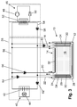
- Fig. 3 shows an exemplary embodiment of a cooling system with an ice storage 10.
- the cooling system has a heat pump 46, which is provided for cooling a coolant.
- the heat pump 46 has a compressor 48 and an expansion valve 50.
- the construction and operation of a heat pump 46 are known in the art. Therefore, this will not be discussed further.
- the cooling device 38 may be a cooling rack, which is set up for receiving goods in a supermarket.
- the goods include, for example, meat, sausages, poultry and / or fruits and vegetables.
- the cooling device 38 has a cooling unit 40.
- the cooling unit 40 has a heat exchanger 42, here in the example a plate-shaped heat exchanger 42, and a fan 44. Air is passed via the fan 44 via the heat exchanger 42, whereby the air cools. The cooled air is then circulated within the cooling device 38. Furthermore, side walls of the cooling device 38, which surround a goods space, can be cooled via the heat exchanger 42.
- the heat exchanger 52 is connected to a flow 54 and a return 56 of the cooling device 38.
- a pump 58 is arranged, which serves as a feed pump for transporting the guided in the cooling system coolant.
- the pump 58 is in particular a speed-controlled pump.
- the pump 58 is disposed in the part of the cooling system which the coolant can supply a plurality of cooling devices 38.
- Fig. 3 only a single cooling device 38 is shown and therefore the cooling circuit consisting of the flow 54 and from the return 56 made simple. In further embodiments, however, a plurality of cooling devices 38 connected in parallel can be provided.
- the coolant is then guided in each case in a flow of the corresponding cooling means 38.
- the returns of the respective cooling devices 38 are then connected to one another via a common return line.
- the flow 54 of the cooling system is equal to the flow 54 of the cooling device 38 and the return 56 of the cooling system equal to the return 56 of the cooling device 38.
- the cooling device 38 has a decentralized pump 62, which is also provided as a speed-controlled pump for delivering coolant. It can be controlled via the pump 62, which amount of coolant is to be supplied to the cooling unit 40.
- the pump 62 controls the mass flow of the coolant within the cooling device 38.
- the pump 58 regulates the mass flow within the cooling system.
- a cooling device 38 could be dispensed with such an embodiment, for example, the pump 58.
- the pump 62 provides on-demand coolant supply to the cooling unit 40.
- the flow 54 has a parallel flow path for the coolant formed by the first conduit assembly 18.
- a pump 60 is arranged in the lead of the line assembly 18.
- the pump 60 is also a speed controlled pump and controls the mass flow and flow of the coolant through the first one Line arrangement 18.
- the ice storage 10 is designed accordingly as the in Fig. 1 Ice storage shown.
- a coolant is cooled by the heat pump 46 and thereby also the coolant guided in the cooling system.
- the coolant in the flow 54 and in the return 56 is circulated.
- the pump 60 is active and leads coolant through the first line assembly 18 through the ice storage 18, so that there is a charge of the ice storage 10.
- the flow rate of coolant can be additionally increased via the pump 62.
- the coolant, which is conveyed via the pump 58, is divided into two flow paths.
- a second conduit arrangement 20 and a third conduit arrangement 22 are arranged parallel to the return 56.
- a pump 66 is arranged in the flow of the second line arrangement 20.
- a pump 64 is arranged in the flow of the third line arrangement 22.
- the pumps 60, 64 and 66 are also speed controlled pumps and regulate the amount of refrigerant which is passed through the second conduit assembly 20 and through the third conduit assembly 22, respectively.
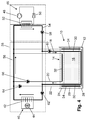
- Fig. 4 shows the cooling system of Fig. 3 in a first mode.
- the arrows indicate the flow direction of the coolant.
- the cooled via the heat pump 46 coolant is supplied within the flow 54 via the pump 58 and the pump 60 of the first conduit assembly 18.
- the distribution of the coolant flow is dependent on the delivery rate of the individual pumps 58, 60 and 62. If the delivery rate of the pump 62 were significantly higher than the delivery rate of the pump 60, a parallel flow through the bridged line section in the supply line 54 could also occur.
- Fig. 4 shows the cooling system of Fig. 3 in a first mode.
- the arrows indicate the flow direction of the coolant.
- the cooled via the heat pump 46 coolant is supplied within the flow 54 via the pump 58 and the pump 60 of the first conduit assembly 18.
- the distribution of the coolant flow is dependent on the delivery rate of the individual pumps 58, 60 and 62. If the delivery rate of the pump 62 were significantly higher than the delivery rate of the pump 60, a parallel
- the coolant flows through the first line arrangement 18 and cools the fluid 16 received in the storage space 14. Subsequently, the coolant is supplied via the pump 62 to the cooling unit 40 and via the return 56 to the heat exchanger 52. About the heat exchanger 52, the coolant is cooled again.
- the coolant circulated in the supply line 54 and in the return line 56 for cooling the cooling unit 40 is not cooled via the heat exchanger 52 but via the "cold" stored in the ice storage device 10.
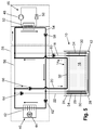
- the pump 60 is deactivated, so that no more coolant flows through the first line arrangement 18.
- the coolant, which has been heated via the cooling unit 40 is guided in the return line 56 via the second line arrangement 20 through the upper region 24 of the ice store 10.
- the pump 66 is activated and thus promotes the heated coolant in the return line 56 via the ice storage 10.
- the coolant which was cooled in the ice storage 10, flows back via the heat exchanger 52 and the feed line 54 directly to the cooling unit 40. Since the cooling takes place via the ice storage 10, the coolant in the return upstream of the heat exchanger 52 already has the required temperature, so that the heat pump 56 does not have to be operated to to cool the coolant.
- the return 56 may be provided a temperature measuring device which detects the temperature of the coolant.
- the cooling system has measuring devices for detecting the temperature of the coolant at further points. This information is forwarded to a control unit for controlling the overall refrigeration system and / or subordinate control and regulation units, such as for the cooling device 38. These then control the coolant delivery by controlling the pumps 58, 60, 62, 64 and 66.
- the heat pump 46 is reactivated and the coolant is cooled by the heat exchanger 52. Accordingly, then the pumps 60 and 66 are controlled so that the coolant is supplied via the pump 60 of the first line assembly 18 so that the ice storage 10 can be loaded and the pump 66 is deactivated so that no heated coolant flows through the second line assembly 20 in the return 56 ,
- the flow of the coolant within the line assemblies 18, 20 and 22 and in the flow 54 and 56 can be done solely by controlling the speed of the pump 60, 62, 64 and 66.
- Cooling device 38 shown additionally has a third line arrangement 22.
- the function of the third conduit arrangement 22 has already been described with reference to FIG Fig. 1 described. Therefore, the third line arrangement 22 is to be regarded as optional.
- the function of the third line arrangement 22 can also be assumed via the second line arrangement 20 alone.
- a third conduit arrangement 22 may be provided to provide a defined regeneration, as already described in the prior art, can be performed.
- the arrangement of the second conduit arrangement 20 in the upper region 24 within the ice storage 10 makes it possible to bring the coolant in the second operating mode essentially to the temperature which the fluid 16 has in the region 24.
- the coolant would also flow through the areas 26 and 28, which have higher temperatures than the area 24.
- the coolant is not cooled as much as it would be necessary for cooling the cooling unit 40.
- a larger amount of refrigerant is passed through an ice storage, resulting in faster discharge of the ice storage and reduces the cycle times of heat pumps, which significantly increases energy costs.
- a clocking of a heat pump, cooling of the cooling unit 40, and cooling of the fluid 16 stored in the ice storage 10 and the intervals between the times of turning on the heat pump 46 can be reduced.
- the cooling system described herein enables a cooling device 38 to be cooled inexpensively and efficiently.
- the ice storage 10 may be loaded when the cost of power to operate the heat pump 46 is low. This can be the case, for example, at night. A cheap electricity tariff can also prevail during the day at certain times. Decisive for this is sometimes the electricity supply generated by renewable energies.
- the day is then on the in Fig. 5 shown Switched mode so that the heat pump is inactive. This can be done until the temperature in the return 56 upstream of the heat exchanger 52 exceeds a threshold.
- the in Fig. 5 shown operating mode are maintained at night.
- refrigeration devices 38 for supermarkets for refrigerating goods have closure devices with a roller blind.
- the roller blind is shut down at night, so that the goods space is closed and a lower heat transfer between the environment of the cooling device 38 and the goods space occurs.
- the coolant may be cooled to 0 degrees by passing it through the area 24 over the second conduit assembly 20.
- a larger heat transfer between the environment and the goods space takes place.
- new goods are always used in the cooling device 38, so that a larger cooling is required.
- a coolant can be brought to a lower temperature, wherein the in Fig. 4 shown operating mode can be used.
- a third conduit assembly 22 may be dispensed with.
- An essential component is the second line arrangement 20, which extends horizontally in the upper region 24 of the storage space 14 and is located substantially within a temperature layer. This can be done by the second line arrangement 20 guided coolant are brought to a defined temperature and does not flow through different temperature stratifications.
Landscapes
- Engineering & Computer Science (AREA)
- Chemical & Material Sciences (AREA)
- Combustion & Propulsion (AREA)
- Physics & Mathematics (AREA)
- Mechanical Engineering (AREA)
- Thermal Sciences (AREA)
- General Engineering & Computer Science (AREA)
- Devices That Are Associated With Refrigeration Equipment (AREA)
Priority Applications (1)
| Application Number | Priority Date | Filing Date | Title |
|---|---|---|---|
| PL16155238T PL3076105T3 (pl) | 2015-03-30 | 2016-02-11 | System chłodzenia |
Applications Claiming Priority (2)
| Application Number | Priority Date | Filing Date | Title |
|---|---|---|---|
| DE102015104901 | 2015-03-30 | ||
| DE102015117948.2A DE102015117948B4 (de) | 2015-03-30 | 2015-10-21 | Kältespeicher und Kühlsystem |
Publications (3)
| Publication Number | Publication Date |
|---|---|
| EP3076105A2 true EP3076105A2 (fr) | 2016-10-05 |
| EP3076105A3 EP3076105A3 (fr) | 2016-12-07 |
| EP3076105B1 EP3076105B1 (fr) | 2021-11-24 |
Family
ID=55359427
Family Applications (1)
| Application Number | Title | Priority Date | Filing Date |
|---|---|---|---|
| EP16155238.5A Active EP3076105B1 (fr) | 2015-03-30 | 2016-02-11 | Système de refroidissement |
Country Status (4)
| Country | Link |
|---|---|
| EP (1) | EP3076105B1 (fr) |
| DK (1) | DK3076105T3 (fr) |
| ES (1) | ES2905089T3 (fr) |
| PL (1) | PL3076105T3 (fr) |
Family Cites Families (7)
| Publication number | Priority date | Publication date | Assignee | Title |
|---|---|---|---|---|
| US4787444A (en) * | 1983-12-19 | 1988-11-29 | Countryman James H | Heating and cooling system |
| US5944089A (en) * | 1994-05-26 | 1999-08-31 | Roland; Russel Anthony | Thermal storage systems for buildings |
| JPH11183012A (ja) * | 1997-12-22 | 1999-07-06 | Shinsei Reizou Kogyo Kk | オープンショーケース、冷蔵庫等の冷蔵方法 |
| JP3402271B2 (ja) * | 1999-07-12 | 2003-05-06 | ダイキン工業株式会社 | 冷凍装置 |
| US6216486B1 (en) * | 1999-09-24 | 2001-04-17 | Baltimore Aircoil Company, Inc. | Ice storage coil arrangement |
| FR2984470A1 (fr) * | 2011-12-16 | 2013-06-21 | Cheikh Moncef Ben | Systeme de climatisation par stockage de froid a l'energie solaire |
| DE202012103715U1 (de) * | 2012-09-27 | 2012-12-14 | Viessmann Kältetechnik AG | Einrichtung zur Bestimmung des Ladezustands eines thermischen Speichers |
-
2016
- 2016-02-11 DK DK16155238.5T patent/DK3076105T3/da active
- 2016-02-11 EP EP16155238.5A patent/EP3076105B1/fr active Active
- 2016-02-11 PL PL16155238T patent/PL3076105T3/pl unknown
- 2016-02-11 ES ES16155238T patent/ES2905089T3/es active Active
Non-Patent Citations (1)
| Title |
|---|
| None |
Also Published As
| Publication number | Publication date |
|---|---|
| EP3076105A3 (fr) | 2016-12-07 |
| EP3076105B1 (fr) | 2021-11-24 |
| ES2905089T3 (es) | 2022-04-07 |
| DK3076105T3 (da) | 2022-02-14 |
| PL3076105T3 (pl) | 2022-04-04 |
Similar Documents
| Publication | Publication Date | Title |
|---|---|---|
| EP3619483B1 (fr) | Meuble frigorifique avec reservoir, systeme de refroidissement et procede de commande d'un meuble frigorifique avec reservoir | |
| EP3355717B1 (fr) | Installation et procédé pour la pasteurisation de produits alimentaires | |
| DE10361645B4 (de) | Kühlsystem zum Kühlen von wärmeerzeugenden Einrichtungen in einem Flugzeug | |
| DE60204065T2 (de) | Aufbewahrungsgerät, insbesondere für verderbliche Waren bei einer vorgewählten Temperatur | |
| DE112007002526T5 (de) | Temperatursteuersystem mit Wärmetauschermodulen mit indirekter Expansionskühlung und innenliegender elektrischer Beheizung | |
| DE102010041951A1 (de) | Kältegerät mit einem Kältespeicher | |
| DE102015117948B4 (de) | Kältespeicher und Kühlsystem | |
| EP2713130B1 (fr) | Accumulateur thermique pour installations de refroidissement | |
| DE19735584C2 (de) | Doppelwandige Kühlzelle | |
| EP3635318B1 (fr) | Système de régulateur thermique à changement d'état avec un régulateur thermique à changement d'état et procédé pour faire fonctionner un système de régulateur thermique à changement d'état | |
| EP3587968B1 (fr) | Système fluidique | |
| DE202012103715U1 (de) | Einrichtung zur Bestimmung des Ladezustands eines thermischen Speichers | |
| EP3076111B1 (fr) | Système fluidique et procédé de commande d'un système fluidique | |
| EP3076105B1 (fr) | Système de refroidissement | |
| DE202012103718U1 (de) | Einrichtung zur Bestimmung des Ladezustands eines segmentierten thermischen Speichers | |
| EP3076109B1 (fr) | Systeme de refroidissement et procede de fonctionnement du systeme de refroidissement | |
| DE102006061155A1 (de) | Kältegerät | |
| EP2126486B1 (fr) | Appareil frigorifique | |
| EP2713120A2 (fr) | Accumulateur thermique pour chambre de refroidissement accessibles | |
| EP3076108B1 (fr) | Dispositif frigorifique et procede de fonctionnement d'un dispositif frigorifique | |
| EP2713121A2 (fr) | Dispositif de refroidissement pour un mode de refroidissement partiellement sans courant | |
| DE102012207682A1 (de) | Haushaltskältegerät mit drei Temperaturerfassungssensoren und Verfahren zum Betreiben eines Haushaltskältegeräts | |
| DE102012207686A1 (de) | Haushaltskältegerät mit zwei kühlbaren Innenräumen und jeweils einem Kältespeicher | |
| CH674133A5 (fr) | ||
| DE102016203461A1 (de) | Mischgetränk-Erzeugungsgerät, Haushaltskältegerät mit einem derartigen Mischgetränk-Erzeugungsgerät sowie Verfahren zum Zubereiten eines Mischgetränks |
Legal Events
| Date | Code | Title | Description |
|---|---|---|---|
| PUAI | Public reference made under article 153(3) epc to a published international application that has entered the european phase |
Free format text: ORIGINAL CODE: 0009012 |
|
| AK | Designated contracting states |
Kind code of ref document: A2 Designated state(s): AL AT BE BG CH CY CZ DE DK EE ES FI FR GB GR HR HU IE IS IT LI LT LU LV MC MK MT NL NO PL PT RO RS SE SI SK SM TR |
|
| AX | Request for extension of the european patent |
Extension state: BA ME |
|
| PUAL | Search report despatched |
Free format text: ORIGINAL CODE: 0009013 |
|
| AK | Designated contracting states |
Kind code of ref document: A3 Designated state(s): AL AT BE BG CH CY CZ DE DK EE ES FI FR GB GR HR HU IE IS IT LI LT LU LV MC MK MT NL NO PL PT RO RS SE SI SK SM TR |
|
| AX | Request for extension of the european patent |
Extension state: BA ME |
|
| RIC1 | Information provided on ipc code assigned before grant |
Ipc: F25D 16/00 20060101ALI20161031BHEP Ipc: F25D 3/00 20060101AFI20161031BHEP |
|
| STAA | Information on the status of an ep patent application or granted ep patent |
Free format text: STATUS: REQUEST FOR EXAMINATION WAS MADE |
|
| 17P | Request for examination filed |
Effective date: 20170607 |
|
| RBV | Designated contracting states (corrected) |
Designated state(s): AL AT BE BG CH CY CZ DE DK EE ES FI FR GB GR HR HU IE IS IT LI LT LU LV MC MK MT NL NO PL PT RO RS SE SI SK SM TR |
|
| STAA | Information on the status of an ep patent application or granted ep patent |
Free format text: STATUS: EXAMINATION IS IN PROGRESS |
|
| 17Q | First examination report despatched |
Effective date: 20190910 |
|
| RAP1 | Party data changed (applicant data changed or rights of an application transferred) |
Owner name: VIESSMANN REFRIGERATION SOLUTIONS GMBH |
|
| GRAP | Despatch of communication of intention to grant a patent |
Free format text: ORIGINAL CODE: EPIDOSNIGR1 |
|
| STAA | Information on the status of an ep patent application or granted ep patent |
Free format text: STATUS: GRANT OF PATENT IS INTENDED |
|
| INTG | Intention to grant announced |
Effective date: 20210629 |
|
| GRAS | Grant fee paid |
Free format text: ORIGINAL CODE: EPIDOSNIGR3 |
|
| GRAA | (expected) grant |
Free format text: ORIGINAL CODE: 0009210 |
|
| STAA | Information on the status of an ep patent application or granted ep patent |
Free format text: STATUS: THE PATENT HAS BEEN GRANTED |
|
| AK | Designated contracting states |
Kind code of ref document: B1 Designated state(s): AL AT BE BG CH CY CZ DE DK EE ES FI FR GB GR HR HU IE IS IT LI LT LU LV MC MK MT NL NO PL PT RO RS SE SI SK SM TR |
|
| REG | Reference to a national code |
Ref country code: GB Ref legal event code: FG4D Free format text: NOT ENGLISH |
|
| REG | Reference to a national code |
Ref country code: DE Ref legal event code: R096 Ref document number: 502016014175 Country of ref document: DE |
|
| REG | Reference to a national code |
Ref country code: AT Ref legal event code: REF Ref document number: 1450157 Country of ref document: AT Kind code of ref document: T Effective date: 20211215 |
|
| REG | Reference to a national code |
Ref country code: IE Ref legal event code: FG4D Free format text: LANGUAGE OF EP DOCUMENT: GERMAN |
|
| REG | Reference to a national code |
Ref country code: DK Ref legal event code: T3 Effective date: 20220210 |
|
| REG | Reference to a national code |
Ref country code: NO Ref legal event code: T2 Effective date: 20211124 |
|
| REG | Reference to a national code |
Ref country code: FI Ref legal event code: FGE Ref country code: NL Ref legal event code: FP |
|
| REG | Reference to a national code |
Ref country code: SE Ref legal event code: TRGR |
|
| REG | Reference to a national code |
Ref country code: LT Ref legal event code: MG9D |
|
| REG | Reference to a national code |
Ref country code: ES Ref legal event code: FG2A Ref document number: 2905089 Country of ref document: ES Kind code of ref document: T3 Effective date: 20220407 |
|
| PG25 | Lapsed in a contracting state [announced via postgrant information from national office to epo] |
Ref country code: RS Free format text: LAPSE BECAUSE OF FAILURE TO SUBMIT A TRANSLATION OF THE DESCRIPTION OR TO PAY THE FEE WITHIN THE PRESCRIBED TIME-LIMIT Effective date: 20211124 Ref country code: LT Free format text: LAPSE BECAUSE OF FAILURE TO SUBMIT A TRANSLATION OF THE DESCRIPTION OR TO PAY THE FEE WITHIN THE PRESCRIBED TIME-LIMIT Effective date: 20211124 Ref country code: BG Free format text: LAPSE BECAUSE OF FAILURE TO SUBMIT A TRANSLATION OF THE DESCRIPTION OR TO PAY THE FEE WITHIN THE PRESCRIBED TIME-LIMIT Effective date: 20220224 |
|
| PG25 | Lapsed in a contracting state [announced via postgrant information from national office to epo] |
Ref country code: IS Free format text: LAPSE BECAUSE OF FAILURE TO SUBMIT A TRANSLATION OF THE DESCRIPTION OR TO PAY THE FEE WITHIN THE PRESCRIBED TIME-LIMIT Effective date: 20220324 Ref country code: PT Free format text: LAPSE BECAUSE OF FAILURE TO SUBMIT A TRANSLATION OF THE DESCRIPTION OR TO PAY THE FEE WITHIN THE PRESCRIBED TIME-LIMIT Effective date: 20220324 Ref country code: LV Free format text: LAPSE BECAUSE OF FAILURE TO SUBMIT A TRANSLATION OF THE DESCRIPTION OR TO PAY THE FEE WITHIN THE PRESCRIBED TIME-LIMIT Effective date: 20211124 Ref country code: HR Free format text: LAPSE BECAUSE OF FAILURE TO SUBMIT A TRANSLATION OF THE DESCRIPTION OR TO PAY THE FEE WITHIN THE PRESCRIBED TIME-LIMIT Effective date: 20211124 Ref country code: GR Free format text: LAPSE BECAUSE OF FAILURE TO SUBMIT A TRANSLATION OF THE DESCRIPTION OR TO PAY THE FEE WITHIN THE PRESCRIBED TIME-LIMIT Effective date: 20220225 |
|
| PG25 | Lapsed in a contracting state [announced via postgrant information from national office to epo] |
Ref country code: SM Free format text: LAPSE BECAUSE OF FAILURE TO SUBMIT A TRANSLATION OF THE DESCRIPTION OR TO PAY THE FEE WITHIN THE PRESCRIBED TIME-LIMIT Effective date: 20211124 Ref country code: SK Free format text: LAPSE BECAUSE OF FAILURE TO SUBMIT A TRANSLATION OF THE DESCRIPTION OR TO PAY THE FEE WITHIN THE PRESCRIBED TIME-LIMIT Effective date: 20211124 Ref country code: RO Free format text: LAPSE BECAUSE OF FAILURE TO SUBMIT A TRANSLATION OF THE DESCRIPTION OR TO PAY THE FEE WITHIN THE PRESCRIBED TIME-LIMIT Effective date: 20211124 Ref country code: EE Free format text: LAPSE BECAUSE OF FAILURE TO SUBMIT A TRANSLATION OF THE DESCRIPTION OR TO PAY THE FEE WITHIN THE PRESCRIBED TIME-LIMIT Effective date: 20211124 Ref country code: CZ Free format text: LAPSE BECAUSE OF FAILURE TO SUBMIT A TRANSLATION OF THE DESCRIPTION OR TO PAY THE FEE WITHIN THE PRESCRIBED TIME-LIMIT Effective date: 20211124 |
|
| REG | Reference to a national code |
Ref country code: DE Ref legal event code: R097 Ref document number: 502016014175 Country of ref document: DE |
|
| PG25 | Lapsed in a contracting state [announced via postgrant information from national office to epo] |
Ref country code: MC Free format text: LAPSE BECAUSE OF FAILURE TO SUBMIT A TRANSLATION OF THE DESCRIPTION OR TO PAY THE FEE WITHIN THE PRESCRIBED TIME-LIMIT Effective date: 20211124 |
|
| PLBE | No opposition filed within time limit |
Free format text: ORIGINAL CODE: 0009261 |
|
| STAA | Information on the status of an ep patent application or granted ep patent |
Free format text: STATUS: NO OPPOSITION FILED WITHIN TIME LIMIT |
|
| PG25 | Lapsed in a contracting state [announced via postgrant information from national office to epo] |
Ref country code: LU Free format text: LAPSE BECAUSE OF NON-PAYMENT OF DUE FEES Effective date: 20220211 Ref country code: AL Free format text: LAPSE BECAUSE OF FAILURE TO SUBMIT A TRANSLATION OF THE DESCRIPTION OR TO PAY THE FEE WITHIN THE PRESCRIBED TIME-LIMIT Effective date: 20211124 |
|
| 26N | No opposition filed |
Effective date: 20220825 |
|
| PG25 | Lapsed in a contracting state [announced via postgrant information from national office to epo] |
Ref country code: SI Free format text: LAPSE BECAUSE OF FAILURE TO SUBMIT A TRANSLATION OF THE DESCRIPTION OR TO PAY THE FEE WITHIN THE PRESCRIBED TIME-LIMIT Effective date: 20211124 |
|
| PG25 | Lapsed in a contracting state [announced via postgrant information from national office to epo] |
Ref country code: IE Free format text: LAPSE BECAUSE OF NON-PAYMENT OF DUE FEES Effective date: 20220211 |
|
| P01 | Opt-out of the competence of the unified patent court (upc) registered |
Effective date: 20230512 |
|
| PG25 | Lapsed in a contracting state [announced via postgrant information from national office to epo] |
Ref country code: HU Free format text: LAPSE BECAUSE OF FAILURE TO SUBMIT A TRANSLATION OF THE DESCRIPTION OR TO PAY THE FEE WITHIN THE PRESCRIBED TIME-LIMIT; INVALID AB INITIO Effective date: 20160211 |
|
| PGFP | Annual fee paid to national office [announced via postgrant information from national office to epo] |
Ref country code: ES Payment date: 20240301 Year of fee payment: 9 Ref country code: NL Payment date: 20240222 Year of fee payment: 9 |
|
| PGFP | Annual fee paid to national office [announced via postgrant information from national office to epo] |
Ref country code: AT Payment date: 20240226 Year of fee payment: 9 |
|
| PG25 | Lapsed in a contracting state [announced via postgrant information from national office to epo] |
Ref country code: MK Free format text: LAPSE BECAUSE OF FAILURE TO SUBMIT A TRANSLATION OF THE DESCRIPTION OR TO PAY THE FEE WITHIN THE PRESCRIBED TIME-LIMIT Effective date: 20211124 Ref country code: CY Free format text: LAPSE BECAUSE OF FAILURE TO SUBMIT A TRANSLATION OF THE DESCRIPTION OR TO PAY THE FEE WITHIN THE PRESCRIBED TIME-LIMIT Effective date: 20211124 |
|
| PGFP | Annual fee paid to national office [announced via postgrant information from national office to epo] |
Ref country code: FI Payment date: 20240220 Year of fee payment: 9 Ref country code: DE Payment date: 20231129 Year of fee payment: 9 Ref country code: GB Payment date: 20240221 Year of fee payment: 9 Ref country code: CH Payment date: 20240301 Year of fee payment: 9 |
|
| PGFP | Annual fee paid to national office [announced via postgrant information from national office to epo] |
Ref country code: SE Payment date: 20240222 Year of fee payment: 9 Ref country code: PL Payment date: 20240129 Year of fee payment: 9 Ref country code: NO Payment date: 20240220 Year of fee payment: 9 Ref country code: IT Payment date: 20240227 Year of fee payment: 9 Ref country code: FR Payment date: 20240227 Year of fee payment: 9 Ref country code: DK Payment date: 20240222 Year of fee payment: 9 Ref country code: BE Payment date: 20240222 Year of fee payment: 9 |
|
| PG25 | Lapsed in a contracting state [announced via postgrant information from national office to epo] |
Ref country code: MT Free format text: LAPSE BECAUSE OF FAILURE TO SUBMIT A TRANSLATION OF THE DESCRIPTION OR TO PAY THE FEE WITHIN THE PRESCRIBED TIME-LIMIT Effective date: 20211124 |
|
| REG | Reference to a national code |
Ref country code: DE Ref legal event code: R119 Ref document number: 502016014175 Country of ref document: DE |
|
| REG | Reference to a national code |
Ref country code: DK Ref legal event code: EBP Effective date: 20250228 |
|
| REG | Reference to a national code |
Ref country code: SE Ref legal event code: EUG Ref country code: CH Ref legal event code: PL |
|
| REG | Reference to a national code |
Ref country code: NL Ref legal event code: MM Effective date: 20250301 |
|
| PG25 | Lapsed in a contracting state [announced via postgrant information from national office to epo] |
Ref country code: FI Free format text: LAPSE BECAUSE OF NON-PAYMENT OF DUE FEES Effective date: 20250211 |
|
| PG25 | Lapsed in a contracting state [announced via postgrant information from national office to epo] |
Ref country code: NO Free format text: LAPSE BECAUSE OF NON-PAYMENT OF DUE FEES Effective date: 20250228 |
|
| REG | Reference to a national code |
Ref country code: AT Ref legal event code: MM01 Ref document number: 1450157 Country of ref document: AT Kind code of ref document: T Effective date: 20250211 |
|
| PG25 | Lapsed in a contracting state [announced via postgrant information from national office to epo] |
Ref country code: AT Free format text: LAPSE BECAUSE OF NON-PAYMENT OF DUE FEES Effective date: 20250211 |
|
| PG25 | Lapsed in a contracting state [announced via postgrant information from national office to epo] |
Ref country code: CH Free format text: LAPSE BECAUSE OF NON-PAYMENT OF DUE FEES Effective date: 20250228 |
|
| GBPC | Gb: european patent ceased through non-payment of renewal fee |
Effective date: 20250211 |
|
| PG25 | Lapsed in a contracting state [announced via postgrant information from national office to epo] |
Ref country code: NL Free format text: LAPSE BECAUSE OF NON-PAYMENT OF DUE FEES Effective date: 20250301 |
|
| REG | Reference to a national code |
Ref country code: BE Ref legal event code: MM Effective date: 20250228 |
|
| PG25 | Lapsed in a contracting state [announced via postgrant information from national office to epo] |
Ref country code: TR Free format text: LAPSE BECAUSE OF FAILURE TO SUBMIT A TRANSLATION OF THE DESCRIPTION OR TO PAY THE FEE WITHIN THE PRESCRIBED TIME-LIMIT Effective date: 20211124 |
|
| PG25 | Lapsed in a contracting state [announced via postgrant information from national office to epo] |
Ref country code: DE Free format text: LAPSE BECAUSE OF NON-PAYMENT OF DUE FEES Effective date: 20250902 |
|
| PG25 | Lapsed in a contracting state [announced via postgrant information from national office to epo] |
Ref country code: GB Free format text: LAPSE BECAUSE OF NON-PAYMENT OF DUE FEES Effective date: 20250211 |
|
| PG25 | Lapsed in a contracting state [announced via postgrant information from national office to epo] |
Ref country code: DK Free format text: LAPSE BECAUSE OF NON-PAYMENT OF DUE FEES Effective date: 20250228 |
|
| PG25 | Lapsed in a contracting state [announced via postgrant information from national office to epo] |
Ref country code: IT Free format text: LAPSE BECAUSE OF NON-PAYMENT OF DUE FEES Effective date: 20250211 Ref country code: FR Free format text: LAPSE BECAUSE OF NON-PAYMENT OF DUE FEES Effective date: 20250228 |
|
| PG25 | Lapsed in a contracting state [announced via postgrant information from national office to epo] |
Ref country code: BE Free format text: LAPSE BECAUSE OF NON-PAYMENT OF DUE FEES Effective date: 20250228 |
|
| REG | Reference to a national code |
Ref country code: ES Ref legal event code: FD2A Effective date: 20260327 |
|
| PG25 | Lapsed in a contracting state [announced via postgrant information from national office to epo] |
Ref country code: ES Free format text: LAPSE BECAUSE OF NON-PAYMENT OF DUE FEES Effective date: 20250212 |
|
| PG25 | Lapsed in a contracting state [announced via postgrant information from national office to epo] |
Ref country code: PL Free format text: LAPSE BECAUSE OF NON-PAYMENT OF DUE FEES Effective date: 20250211 |