EP3076105A2 - Kältespeicher und kühlsystem - Google Patents
Kältespeicher und kühlsystem Download PDFInfo
- Publication number
- EP3076105A2 EP3076105A2 EP16155238.5A EP16155238A EP3076105A2 EP 3076105 A2 EP3076105 A2 EP 3076105A2 EP 16155238 A EP16155238 A EP 16155238A EP 3076105 A2 EP3076105 A2 EP 3076105A2
- Authority
- EP
- European Patent Office
- Prior art keywords
- coolant
- cooling
- arrangement
- line
- conduit
- Prior art date
- Legal status (The legal status is an assumption and is not a legal conclusion. Google has not performed a legal analysis and makes no representation as to the accuracy of the status listed.)
- Granted
Links
Images

Classifications
-
- F—MECHANICAL ENGINEERING; LIGHTING; HEATING; WEAPONS; BLASTING
- F25—REFRIGERATION OR COOLING; COMBINED HEATING AND REFRIGERATION SYSTEMS; HEAT PUMP SYSTEMS; MANUFACTURE OR STORAGE OF ICE; LIQUEFACTION SOLIDIFICATION OF GASES
- F25D—REFRIGERATORS; COLD ROOMS; ICE-BOXES; COOLING OR FREEZING APPARATUS NOT OTHERWISE PROVIDED FOR
- F25D16/00—Devices using a combination of a cooling mode associated with refrigerating machinery with a cooling mode not associated with refrigerating machinery
-
- F—MECHANICAL ENGINEERING; LIGHTING; HEATING; WEAPONS; BLASTING
- F25—REFRIGERATION OR COOLING; COMBINED HEATING AND REFRIGERATION SYSTEMS; HEAT PUMP SYSTEMS; MANUFACTURE OR STORAGE OF ICE; LIQUEFACTION SOLIDIFICATION OF GASES
- F25D—REFRIGERATORS; COLD ROOMS; ICE-BOXES; COOLING OR FREEZING APPARATUS NOT OTHERWISE PROVIDED FOR
- F25D3/00—Devices using other cold materials; Devices using cold-storage bodies
- F25D3/005—Devices using other cold materials; Devices using cold-storage bodies combined with heat exchangers
-
- F—MECHANICAL ENGINEERING; LIGHTING; HEATING; WEAPONS; BLASTING
- F25—REFRIGERATION OR COOLING; COMBINED HEATING AND REFRIGERATION SYSTEMS; HEAT PUMP SYSTEMS; MANUFACTURE OR STORAGE OF ICE; LIQUEFACTION SOLIDIFICATION OF GASES
- F25D—REFRIGERATORS; COLD ROOMS; ICE-BOXES; COOLING OR FREEZING APPARATUS NOT OTHERWISE PROVIDED FOR
- F25D2303/00—Details of devices using other cold materials; Details of devices using cold-storage bodies
- F25D2303/08—Devices using cold storage material, i.e. ice or other freezable liquid
- F25D2303/082—Devices using cold storage material, i.e. ice or other freezable liquid disposed in a cold storage element not forming part of a container for products to be cooled, e.g. ice pack or gel accumulator
- F25D2303/0822—Details of the element
Definitions
- the cooling system has at least one cooling machine, which is designed to cool the coolant and is coupled to the line system of the cooling system.
- Cold storage are known from the prior art, which are designed for example as an ice storage.
- the coolant is passed through the ice storage via a line arrangement.
- the coolant which has been cooled by a refrigerator, is guided in a first direction through the ice storage and fed to a cooling device with a consumer. Subsequently, the coolant is supplied from the consumer back to the chiller, wherein the process is repeated.
- the coolant can be passed through a further line arrangement opposite through the ice storage, wherein the further line arrangement is arranged so that it leads over the consumer heated coolant through the ice storage.
- the ice contained in the ice storage absorbs the heat contained in the refrigerant, so that the refrigerant is cooled and can be supplied to the consumer again.
- the known from the prior art ice storage are designed so that an optimal regeneration of the ice storage occurs. Accordingly, the line assemblies within the ice storage are arranged so that the coolant flows through the ice storage vertically.
- the coolant Since set in the ice storage certain temperature layers, but no optimal cooling of the coolant can be achieved. Especially with vertically extending line arrangements, the coolant passes through different temperature layers within the ice storage.
- the arrangement of the second line arrangement makes it possible that the coolant is not passed over a plurality of temperature layers within the cold storage, but is guided only substantially within a range having a certain temperature or a certain temperature range. Due to the vertical arrangement of the first line arrangement can be carried out on these a loading and regeneration of the cold storage, as known from the prior art.
- the horizontal arrangement of the second conduit arrangement makes it possible to guide a heated coolant within the range of the fluid, which has, for example, 0 degrees Celsius.
- the guided in the second conduit arrangement coolant is not passed through other temperature ranges of the fluid and can thereby assume substantially the temperature of the area in which the second conduit arrangement extends.
- the second line arrangement may be arranged in further embodiments in an upper region of the storage space.
- a certain temperature arises in the upper region of the cold accumulator, for example an ice accumulator. This temperature is maintained over a wide operating range of the cold accumulator, regardless of whether or not ice has formed within the cold accumulator. This makes it possible to cool the coolant at a certain temperature even when the cold storage is not or not fully loaded. Because the second line arrangement is arranged in the upper region of the storage space, the coolant does not have to be conducted over a plurality of temperature ranges within the storage space.
- the cold storage may have a third line arrangement which is arranged in the storage space, wherein the third line arrangement is arranged such that coolant passed through the third line arrangement flows through the cold store vertically and opposite to the flow direction of the coolant guided in the first line arrangement.
- the third line arrangement By means of the third line arrangement, a further cooling of the coolant can be achieved, whereby a targeted defrosting is possible analogously to the ice stores known from the prior art.
- the cold storage may also have a plurality of mutually parallel second line arrangements in other embodiments.
- the conduit arrangements can be arranged at different distances from each other within the storage space, so that the coolant can be cooled at different temperatures.
- the area in which is arranged a first line arrangement of the second line arrangements is a temperature between 0 and 3 degrees Celsius.
- a second line arrangement of the second line arrangements can be arranged, for example, in a temperature range between 3 and 4 degrees Celsius and a third line arrangement of the second line arrangements can be arranged in a temperature range between 4 and 5 degrees Celsius.
- the second line arrangements can be connected via valves or other coupling devices to a flow of a cooling system.
- both the first line arrangement and the at least one second line arrangement have in their respective flow sections a speed-controlled pump which regulates the coolant flow in the respective line arrangements.
- a speed-controlled pump can also be arranged in the third line arrangement.
- the first line arrangement, the second line arrangement and / or the third line arrangement may have at least one heat exchanger and / or helically extending line sections.
- the heat exchangers and / or helical line sections provide a large transition surface for heat transfer between the fluid stored in the cold accumulator and the coolant. As a result, the cooling of the coolant can be further improved. In addition, it is possible to load the cold storage faster.
- the fluid received in the storage space may in other embodiments be water.
- a brine for example, a water-glycol mixture may also be performed in the line sections.
- defined temperature ranges are often established.
- the water in the bottom area of the cold storage at a temperature of 4 degrees Celsius, since at this temperature, the water has its highest density. In the upper area, the water usually has 0 degrees Celsius. If, in a conventional embodiment of the cold accumulator, cooling of the coolant would then be carried out via vertically extending line arrangements, it would be almost impossible-depending on the return temperature of the coolant-to bring the sols carried in the lines to 0 degrees Celsius.
- the coolant is also guided through areas within the cold accumulator, which are warmer than 0 degrees Celsius.
- the coolant may However, be brought selectively to a temperature of 0 degrees Celsius, since the coolant is passed through the second line arrangement, for example, only in the upper region within the cold storage.
- the above-mentioned temperature distribution is particularly independent of whether the ice storage is almost completely loaded or almost completely discharged.
- a defined cooling of the coolant can be achieved over a wide load state of the cold accumulator.
- memory elements can be accommodated in other embodiments, which consist of a phase change material or have a phase change material.
- a phase change material for example, water or again a brine can be used.
- Such storage elements may be plates with openings, wherein both the fluid and water can flow through the openings and the line arrangements are guided.
- the storage elements may also be balls filled with phase change material.
- the cold storage is designed as an ice storage.
- the ice storage is cooled for loading via the first conduit arrangement. This results in the formation of ice in the water, with defined temperature ranges set within the ice storage.
- the first line arrangement, the second line arrangement and / or the third line arrangement can be coupled via valves to the flow or the return of the cooling system.
- the first line arrangement, the second line arrangement and the third line arrangement have in their respective flow lines a pump via which the coolant is conducted from the flow line or return line of the cooling system through the cold storage becomes.
- valves can be dispensed with in such embodiments.
- About the pump is controlled whether a loading of the cold storage or cooling of the cooling device is to be performed on the cold storage.
- the coolant is led out of the return line via the second line arrangement through the cold storage, when the chiller does not perform cooling of the coolant.
- this also means that the chiller will no longer be operated or must be operated when the cooling of the coolant takes place via the second line arrangement.
- the chiller may be, for example, a heat pump. If the heat pump clocked less strong or not be actively operated over a longer period of time, the coolant can be performed only through the second line arrangement through the cold storage and thus cause cooling of the cooling device. The cooled via the second line arrangement and the cold storage coolant is thereby coupled to the heat pump heat exchanger, which connects the return of the cooling system, in particular the cooling device, with the flow of the cooling system, in particular the cooling device passes. The coolant then has a temperature which is usually below the temperature prevailing in the return. A measuring device detects the temperature, which is detected by a control and control unit that switching on the heat pump is not required because the temperature in the return is below a threshold.
- the cooled coolant is supplied via the flow of the cooling device or the cooling system to the heat exchanger of the cooling device and heated. From the heat exchanger, the coolant is again guided through the second line arrangement through the cold storage and cooled. This process can be carried out until the temperature rises, for example, in the upper region of the cold storage and thus also the temperature in the return of the cooling system or the cooling device.
- a sensor arrangement detects an increase in temperature and activates the heat pump so that the heat exchanger of the heat pump, the coolant is brought to a certain temperature.
- the designated control and control unit then deactivates the arranged in the flow of the second line arrangement pump and activated in the flow of the first line arrangement arranged pump so that the cooled via the heat pump coolant flows through the first line arrangement and thus cools the cold storage and then via the cold storage in the flow of the cooling device or the cooling system is introduced and passes to the heat exchanger of the cooling device.
- the pumps arranged in the cooling system may preferably be speed-controlled pumps. This makes it easy to control the operation of the pumps and to set different mass flows.
- valves can be dispensed with via the control of the pumps.
- the cooling device can be a cooling rack which is provided for receiving and cooling goods such as dairy products, meat, poultry and / or fruit and vegetables.
- the coolant is cooled by the heat pump and thereby also the cold storage, preferably a water-filled ice storage, cooled, ie loaded.
- the cold storage preferably a water-filled ice storage, cooled, ie loaded.
- the low cooling power that is then required can be provided via the cold storage, wherein as stated above, the coolant is guided via the second line arrangement.
- the temperature rise is detected by a sensor arrangement and transmitted to a control and regulating device, which then activates the heat pump again.
- the heat pump can be operated until the cold storage is completely loaded.
- the cooling of the cooling device can take place essentially via the cold storage.
- the coolant is guided within the cooling circuit of the cooling device or the cooling system via the second line arrangement.
- the second line arrangement can be arranged in the upper region of the cold storage, and especially in water as a fluid for the cold storage, the temperature in the upper region of the cold storage over a wide load state of the cold storage remains constant, can provide optimal and long-lasting cooling.
- Fig. 1 shows a schematic representation of an ice storage 10 of a first embodiment.
- the ice storage 10 has a housing 12.
- the housing 12 in addition to indicated side walls and a bottom element and a ceiling element.
- the ceiling element is in Fig. 1 not shown.
- a fluid 16 is received in the ice storage 10.
- the fluid 16 is preferably water.
- the water may be mixed with other additives to influence certain properties of the water or to achieve certain properties of the fluid 16.
- the housing 12 surrounds a storage space 14, in which a first line arrangement 18, a second line arrangement 20 and a third line arrangement 22 are arranged.
- the first Conduit assembly 18 is arranged so that a guided via the first conduit arrangement 18 coolant flows through the storage space 14 and thus the fluid 16 in the direction shown.
- the coolant guided in the first line arrangement 18 flows through two heat exchangers 30 vertically, wherein the coolant can also be guided over sections of the first line arrangement 18 parallel to the floor. If the coolant is passed through the ice storage 10 via the first line arrangement 18, a defined formation of ice in the storage space 14 occurs. Via the third line arrangement 22, a coolant can be guided in the opposite direction through the storage space 14 of the ice store 10.
- the first line arrangement is connected to a flow of a cooling system, so that cooled coolant flows through the ice storage 10 in order to charge it, ie to cool it.
- the guided through the ice storage 10 coolant absorbs heat.
- a heated coolant through the third line assembly 22 through the ice storage 10 is performed.
- the heated coolant within the conduit of the third conduit arrangement 22 releases heat to the fluid 16 or to the fluid 16 that has become ice, wherein the coolant guided in the third conduit arrangement 22 cools.
- heat exchangers 34 are provided in the third conduit arrangement 22, which provide a large heat transfer surface.
- the third line arrangement 22 is connected downstream of a consumer in the return of a cooling system.
- a defined loading of an ice storage and a defined regeneration i. H. Melting of the ice
- the first line arrangement and the third line arrangement are formed in conventional ice storage so that the coolant guided therein flows vertically through the ice storage. If the refrigeration stored in the ice storage is to be used to cool a coolant, it is passed through the ice storage 10 via the third line arrangement 22. Due to the different temperature layers in the areas 24, 26 and 28, however, the coolant can not be optimally cooled. This is because the coolant is also guided by temperature zones within the storage space 14 of the ice storage 10, which are above a desired coolant temperature.
- ice storage 10 is for optimal cooling of a coolant in the return of a cooling system a second conduit arrangement 20 is arranged.
- the second conduit arrangement 20, like the third conduit arrangement 22, is arranged in the return of a cooling system and can be flowed through by a heated coolant coming from a consumer in the cooling system.
- the second conduit arrangement 20 is arranged and configured such that the coolant, which is guided through the second conduit arrangement 20, flows through the upper area 24 horizontally. In this area, the water or fluid 16 has a temperature of 0 degrees Celsius.
- the coolant guided in the second conduit arrangement 20 can be cooled down more, since the coolant does not pass through different temperature layers.
- the second conduit assembly 20 may also include a heat exchanger 32 that provides a large transfer surface for heat transfer.
- the heat exchangers 30, 32 and 34 may be formed differently.
- these heat exchangers 30, 32 and 34 are formed by line sections which extend helically over the entire surface of a side wall or over the base surface of the housing 12.
- Fig. 2 shows a second embodiment of an ice storage 10.
- the in Fig. 2 shown embodiment of the ice storage 10 is different from that in Fig. 1 shown ice storage in that 14 storage elements 16 are arranged in the storage space.
- the storage elements 16 have a plastic shell in which a brine is received.
- the brine serves as a phase change material and stores cold, which is transmitted through the guided in the first conduit assembly 18 coolant.
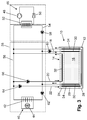
- Fig. 3 shows an exemplary embodiment of a cooling system with an ice storage 10.
- the cooling system has a heat pump 46, which is provided for cooling a coolant.
- the heat pump 46 has a compressor 48 and an expansion valve 50.
- the construction and operation of a heat pump 46 are known in the art. Therefore, this will not be discussed further.
- the cooling device 38 may be a cooling rack, which is set up for receiving goods in a supermarket.
- the goods include, for example, meat, sausages, poultry and / or fruits and vegetables.
- the cooling device 38 has a cooling unit 40.
- the cooling unit 40 has a heat exchanger 42, here in the example a plate-shaped heat exchanger 42, and a fan 44. Air is passed via the fan 44 via the heat exchanger 42, whereby the air cools. The cooled air is then circulated within the cooling device 38. Furthermore, side walls of the cooling device 38, which surround a goods space, can be cooled via the heat exchanger 42.
- the heat exchanger 52 is connected to a flow 54 and a return 56 of the cooling device 38.
- a pump 58 is arranged, which serves as a feed pump for transporting the guided in the cooling system coolant.
- the pump 58 is in particular a speed-controlled pump.
- the pump 58 is disposed in the part of the cooling system which the coolant can supply a plurality of cooling devices 38.
- Fig. 3 only a single cooling device 38 is shown and therefore the cooling circuit consisting of the flow 54 and from the return 56 made simple. In further embodiments, however, a plurality of cooling devices 38 connected in parallel can be provided.
- the coolant is then guided in each case in a flow of the corresponding cooling means 38.
- the returns of the respective cooling devices 38 are then connected to one another via a common return line.
- the flow 54 of the cooling system is equal to the flow 54 of the cooling device 38 and the return 56 of the cooling system equal to the return 56 of the cooling device 38.
- the cooling device 38 has a decentralized pump 62, which is also provided as a speed-controlled pump for delivering coolant. It can be controlled via the pump 62, which amount of coolant is to be supplied to the cooling unit 40.
- the pump 62 controls the mass flow of the coolant within the cooling device 38.
- the pump 58 regulates the mass flow within the cooling system.
- a cooling device 38 could be dispensed with such an embodiment, for example, the pump 58.
- the pump 62 provides on-demand coolant supply to the cooling unit 40.
- the flow 54 has a parallel flow path for the coolant formed by the first conduit assembly 18.
- a pump 60 is arranged in the lead of the line assembly 18.
- the pump 60 is also a speed controlled pump and controls the mass flow and flow of the coolant through the first one Line arrangement 18.
- the ice storage 10 is designed accordingly as the in Fig. 1 Ice storage shown.
- a coolant is cooled by the heat pump 46 and thereby also the coolant guided in the cooling system.
- the coolant in the flow 54 and in the return 56 is circulated.
- the pump 60 is active and leads coolant through the first line assembly 18 through the ice storage 18, so that there is a charge of the ice storage 10.
- the flow rate of coolant can be additionally increased via the pump 62.
- the coolant, which is conveyed via the pump 58, is divided into two flow paths.
- a second conduit arrangement 20 and a third conduit arrangement 22 are arranged parallel to the return 56.
- a pump 66 is arranged in the flow of the second line arrangement 20.
- a pump 64 is arranged in the flow of the third line arrangement 22.
- the pumps 60, 64 and 66 are also speed controlled pumps and regulate the amount of refrigerant which is passed through the second conduit assembly 20 and through the third conduit assembly 22, respectively.
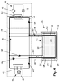
- Fig. 4 shows the cooling system of Fig. 3 in a first mode.
- the arrows indicate the flow direction of the coolant.
- the cooled via the heat pump 46 coolant is supplied within the flow 54 via the pump 58 and the pump 60 of the first conduit assembly 18.
- the distribution of the coolant flow is dependent on the delivery rate of the individual pumps 58, 60 and 62. If the delivery rate of the pump 62 were significantly higher than the delivery rate of the pump 60, a parallel flow through the bridged line section in the supply line 54 could also occur.
- Fig. 4 shows the cooling system of Fig. 3 in a first mode.
- the arrows indicate the flow direction of the coolant.
- the cooled via the heat pump 46 coolant is supplied within the flow 54 via the pump 58 and the pump 60 of the first conduit assembly 18.
- the distribution of the coolant flow is dependent on the delivery rate of the individual pumps 58, 60 and 62. If the delivery rate of the pump 62 were significantly higher than the delivery rate of the pump 60, a parallel
- the coolant flows through the first line arrangement 18 and cools the fluid 16 received in the storage space 14. Subsequently, the coolant is supplied via the pump 62 to the cooling unit 40 and via the return 56 to the heat exchanger 52. About the heat exchanger 52, the coolant is cooled again.
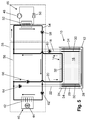
- the coolant circulated in the supply line 54 and in the return line 56 for cooling the cooling unit 40 is not cooled via the heat exchanger 52 but via the "cold" stored in the ice storage device 10.
- the pump 60 is deactivated, so that no more coolant flows through the first line arrangement 18.
- the coolant, which has been heated via the cooling unit 40 is guided in the return line 56 via the second line arrangement 20 through the upper region 24 of the ice store 10.
- the pump 66 is activated and thus promotes the heated coolant in the return line 56 via the ice storage 10.
- the coolant which was cooled in the ice storage 10, flows back via the heat exchanger 52 and the feed line 54 directly to the cooling unit 40. Since the cooling takes place via the ice storage 10, the coolant in the return upstream of the heat exchanger 52 already has the required temperature, so that the heat pump 56 does not have to be operated to to cool the coolant.
- the return 56 may be provided a temperature measuring device which detects the temperature of the coolant.
- the cooling system has measuring devices for detecting the temperature of the coolant at further points. This information is forwarded to a control unit for controlling the overall refrigeration system and / or subordinate control and regulation units, such as for the cooling device 38. These then control the coolant delivery by controlling the pumps 58, 60, 62, 64 and 66.
- the heat pump 46 is reactivated and the coolant is cooled by the heat exchanger 52. Accordingly, then the pumps 60 and 66 are controlled so that the coolant is supplied via the pump 60 of the first line assembly 18 so that the ice storage 10 can be loaded and the pump 66 is deactivated so that no heated coolant flows through the second line assembly 20 in the return 56 ,
- the flow of the coolant within the line assemblies 18, 20 and 22 and in the flow 54 and 56 can be done solely by controlling the speed of the pump 60, 62, 64 and 66.
- Cooling device 38 shown additionally has a third line arrangement 22.
- the function of the third conduit arrangement 22 has already been described with reference to FIG Fig. 1 described. Therefore, the third line arrangement 22 is to be regarded as optional.
- the function of the third line arrangement 22 can also be assumed via the second line arrangement 20 alone.
- a third conduit arrangement 22 may be provided to provide a defined regeneration, as already described in the prior art, can be performed.
- the arrangement of the second conduit arrangement 20 in the upper region 24 within the ice storage 10 makes it possible to bring the coolant in the second operating mode essentially to the temperature which the fluid 16 has in the region 24.
- the coolant would also flow through the areas 26 and 28, which have higher temperatures than the area 24.
- the coolant is not cooled as much as it would be necessary for cooling the cooling unit 40.
- a larger amount of refrigerant is passed through an ice storage, resulting in faster discharge of the ice storage and reduces the cycle times of heat pumps, which significantly increases energy costs.
- a clocking of a heat pump, cooling of the cooling unit 40, and cooling of the fluid 16 stored in the ice storage 10 and the intervals between the times of turning on the heat pump 46 can be reduced.
- the cooling system described herein enables a cooling device 38 to be cooled inexpensively and efficiently.
- the ice storage 10 may be loaded when the cost of power to operate the heat pump 46 is low. This can be the case, for example, at night. A cheap electricity tariff can also prevail during the day at certain times. Decisive for this is sometimes the electricity supply generated by renewable energies.
- the day is then on the in Fig. 5 shown Switched mode so that the heat pump is inactive. This can be done until the temperature in the return 56 upstream of the heat exchanger 52 exceeds a threshold.
- the in Fig. 5 shown operating mode are maintained at night.
- refrigeration devices 38 for supermarkets for refrigerating goods have closure devices with a roller blind.
- the roller blind is shut down at night, so that the goods space is closed and a lower heat transfer between the environment of the cooling device 38 and the goods space occurs.
- the coolant may be cooled to 0 degrees by passing it through the area 24 over the second conduit assembly 20.
- a larger heat transfer between the environment and the goods space takes place.
- new goods are always used in the cooling device 38, so that a larger cooling is required.
- a coolant can be brought to a lower temperature, wherein the in Fig. 4 shown operating mode can be used.
- a third conduit assembly 22 may be dispensed with.
- An essential component is the second line arrangement 20, which extends horizontally in the upper region 24 of the storage space 14 and is located substantially within a temperature layer. This can be done by the second line arrangement 20 guided coolant are brought to a defined temperature and does not flow through different temperature stratifications.
Landscapes
- Engineering & Computer Science (AREA)
- Chemical & Material Sciences (AREA)
- Combustion & Propulsion (AREA)
- Physics & Mathematics (AREA)
- Mechanical Engineering (AREA)
- Thermal Sciences (AREA)
- General Engineering & Computer Science (AREA)
- Devices That Are Associated With Refrigeration Equipment (AREA)
Abstract
Description
- Es werden ein Kältespeicher und ein Kühlsystem beschrieben, wobei in dem Kältespeicher ein Fluid aufgenommen ist, das über ein Kühlmittel gekühlt werden kann. Das Kühlsystem weist hierzu mindestens eine Kältemaschine auf, die zum Kühlen des Kühlmittels ausgebildet und mit dem Leitungssystem des Kühlsystems gekoppelt ist.
- Aus dem Stand der Technik sind Kältespeicher bekannt, die beispielsweise als Eisspeicher ausgebildet sind. In den Eisspeichern ist Wasser aufgenommen, welches über ein Kühlmittel gekühlt werden kann. Hierzu wird über eine Leitungsanordnung das Kühlmittel durch den Eisspeicher geführt. Beispielsweise wird das Kühlmittel, das über eine Kältemaschine gekühlt wurde, in einer ersten Richtung durch den Eisspeicher geführt und einer Kühleinrichtung mit einem Verbraucher zugeführt. Anschließend wird das Kühlmittel von dem Verbraucher wieder der Kältemaschine zugeführt, wobei der Vorgang wiederholt wird. Um ein Kühlen ohne die Kältemaschine durchzuführen, kann das Kühlmittel über eine weitere Leitungsanordnung entgegengesetzt durch den Eisspeicher geführt werden, wobei die weitere Leitungsanordnung so angeordnet ist, dass sie über den Verbraucher erwärmtes Kühlmittel durch den Eisspeicher führt. Das in dem Eisspeicher enthaltene Eis nimmt die in dem Kühlmittel enthaltene Wärme auf, sodass das Kühlmittel gekühlt wird und dem Verbraucher wieder zugeführt werden kann.
- Die aus dem Stand der Technik bekannten Eisspeicher sind so ausgebildet, dass eine optimale Regeneration des Eisspeichers auftritt. Entsprechend sind die Leitungsanordnungen innerhalb des Eisspeichers so angeordnet, dass das Kühlmittel den Eisspeicher vertikal durchströmt.
- Da sich im Eisspeicher bestimmte Temperaturschichten einstellen, kann jedoch keine optimale Kühlung des Kühlmittels erreicht werden. Insbesondere bei vertikal verlaufenden Leitungsanordnungen durchläuft das Kühlmittel verschiedene Temperaturschichten innerhalb des Eisspeichers.
- Es ist daher Aufgabe, einen Eisspeicher sowie ein Kühlsystem mit einem Eisspeicher anzugeben, wobei neben einer Regeneration des Eisspeichers eine verbesserte Kühlung eines Kühlmittels durchführbar ist.
- Die Aufgabe wird durch einen Kältespeicher mit den in Anspruch 1 angegebenen technischen Merkmalen und durch ein Kühlsystem mit den in Anspruch 10 angegebenen technischen Merkmalen gelöst. Vorteilhafte Weiterbildungen sind in Unteransprüchen im Detail angegeben.
- Ein Kältespeicher, der die vorstehend genannte Aufgabe löst, weist mindestens auf
- ein Gehäuse, das einen Speicherraum umgibt, wobei in dem Speicherraum ein Fluid aufgenommen ist,
- eine erste Leitungsanordnung, die in dem Speicherraum angeordnet ist, wobei die erste Leitungsanordnung so angeordnet ist, dass über die erste Leitungsanordnung geführtes Kühlmittel den Kältespeicher vertikal durchströmt, und
- eine zweite Leitungsanordnung, die in dem Speicherraum angeordnet ist, wobei die zweite Leitungsanordnung so angeordnet ist, dass über die zweite Leitungsanordnung geführtes Kühlmittel den Kältespeicher horizontal durchströmt.
- Die Anordnung der zweiten Leitungsanordnung ermöglicht es, dass das Kühlmittel nicht über mehrere Temperaturschichten innerhalb des Kältespeichers geführt wird, sondern nur im Wesentlichen innerhalb eines Bereichs geführt ist, der eine bestimmte Temperatur oder einen bestimmten Temperaturbereich aufweist. Aufgrund der vertikalen Anordnung der ersten Leitungsanordnung kann über diese eine Beladung und Regeneration des Kältespeichers, wie aus dem Stand der Technik bekannt, durchgeführt werden. Die horizontale Anordnung der zweiten Leitungsanordnung erlaubt es, ein erwärmtes Kühlmittel innerhalb des Bereichs des Fluids zu führen, welches beispielsweise 0 Grad Celsius aufweist. Das in der zweiten Leitungsanordnung geführte Kühlmittel wird nicht durch weitere Temperaturbereiche des Fluids geführt und kann hierdurch im Wesentlichen die Temperatur des Bereichs annehmen, in welchem die zweite Leitungsanordnung verläuft.
- Die zweite Leitungsanordnung kann in weiteren Ausführungsformen in einem oberen Bereich des Speicherraums angeordnet sein. In Abhängigkeit des verwendeten Fluids stellt sich in dem oberen Bereich des Kältespeichers, bspw. eines Eisspeichers, eine bestimmte Temperatur ein. Diese Temperatur wird über einen weiten Betriebsbereich des Kältespeichers beibehalten, unabhängig davon ob sich innerhalb des Kältespeichers Eis gebildet hat oder nicht. Dadurch ist es möglich, das Kühlmittel mit einer bestimmten Temperatur auch dann zu kühlen, wenn der Kältespeicher nicht oder nicht vollständig beladen ist. Dadurch, dass die zweite Leitungsanordnung im oberen Bereich des Speicherraums angeordnet ist, muss das Kühlmittel auch nicht über mehrere Temperaturbereiche innerhalb des Speicherraums geführt werden.
- Der Kältespeicher kann in weiteren Ausführungen eine dritte Leitungsanordnung aufweisen, die in dem Speicherraum angeordnet ist, wobei die dritte Leitungsanordnung so angeordnet ist, dass über die dritte Leitungsanordnung geführtes Kühlmittel den Kältespeicher vertikal und entgegengesetzt der Strömungsrichtung des in der ersten Leitungsanordnung geführten Kühlmittels durchströmt. Über die dritte Leitungsanordnung kann eine weitere Kühlung des Kühlmittels erreicht werden, wobei analog zu den aus dem Stand der Technik bekannten Eisspeichern ein gezieltes Abtauen möglich ist.
- Der Kältespeicher kann in weiteren Ausführungen auch mehrere parallel zueinander verlaufende zweite Leitungsanordnungen aufweisen. Die Leitungsanordnungen können in verschiedenen Abständen zueinander innerhalb des Speicherraums angeordnet sein, sodass das Kühlmittel mit verschiedenen Temperaturen gekühlt werden kann. Beispielsweise weist der Bereich, in welcher eine erste Leitungsanordnung der zweiten Leitungsanordnungen angeordnet ist eine Temperatur zwischen 0 und 3 Grad Celsius auf. Eine zweite Leitungsanordnung der zweiten Leitungsanordnungen kann beispielweise in einem Temperaturbereich zwischen 3 und 4 Grad Celsius angeordnet und eine dritte Leitungsanordnung der zweiten Leitungsanordnungen kann in einem Temperaturbereich zwischen 4 und 5 Grad Celsius angeordnet sein. Die zweiten Leitungsanordnungen können über Ventile oder andere Koppeleinrichtungen mit einem Vorlauf eines Kühlsystems verbunden sein. In Abhängigkeit der benötigten Kühlung, kann das Kühlmittel dann durch eine der zweiten Leitungsanordnungen geführt werden, um das Kühlmittel auf eine entsprechende Temperatur zu bringen. Vorzugsweise weisen sowohl die erste Leitungsanordnung als auch die mindestens eine zweite Leitungsanordnung in ihren jeweiligen Vorlaufabschnitten eine drehzahlgesteuerte Pumpe auf, die den Kühlmittelstrom in den jeweiligen Leitungsanordnungen regelt. Entsprechend kann auch in der dritten Leitungsanordnung eine drehzahlgesteuerte Pumpe angeordnet sein.
- Die erste Leitungsanordnung, die zweite Leitungsanordnung und/oder die dritte Leitungsanordnung können mit einem Kühlkreislauf verbindbar sein, in dem mindestens ein Wärmetauscher angeordnet ist, wobei
- die erste Leitungsanordnung in Kühlmittelströmungsrichtung vor dem mindestens einen Wärmetauscher im Vorlauf des Kühlkreislaufs angeordnet ist,
- die zweite Leitungsanordnung in Kühlmittelströmungsrichtung nach dem mindestens einen Wärmetauscher im Rücklauf des Kühlkreislaufs angeordnet ist, und/oder
- die dritte Leitungsanordnung in Kühlmittelströmungsrichtung nach dem mindestens einen Wärmetauscher im Rücklauf des Kühlkreislaufs angeordnet ist.
- Die erste Leitungsanordnung, die zweite Leitungsanordnung und/oder die dritte Leitungsanordnung können mindestens einen Wärmetauscher und/oder wendelförmig verlaufende Leitungsabschnitte aufweisen. Die Wärmetauscher und/oder wendelförmigen Leitungsabschnitte bieten eine große Übergangsfläche für einen Wärmeübergang zwischen dem in dem Kältespeicher aufgenommenen Fluid und dem Kühlmittel. Hierdurch kann die Kühlung des Kühlmittels weiter verbessert werden. Zudem ist es möglich, den Kältespeicher schneller zu beladen.
- Das in dem Speicherraum aufgenommene Fluid kann in weiteren Ausführungsformen Wasser sein. Als Kühlmittel kann ferner eine Sole, z.B. ein Wasser-Glykol-Gemisch, in den Leitungsabschnitten geführt sein. Bei einem mit Wasser gefüllten Speicherraum des Kältespeichers stellen sich oftmals definierte Temperaturbereiche ein. So weist das Wasser im Bodenbereich des Kältespeichers eine Temperatur von 4 Grad Celsius auf, da bei dieser Temperatur das Wasser seine höchste Dichte hat. Im oberen Bereich weist das Wasser in der Regel 0 Grad Celsius auf. Würde nun bei einer konventionellen Ausbildung des Kältespeichers ein Kühlen des Kühlmittels über vertikal verlaufende Leitungsanordnungen durchgeführt werden, ist es nahezu unmöglich - in Abhängigkeit der Rücklauftemperatur des Kühlmittels - die in den Leitungen geführte Sole auf 0 Grad Celsius zu bringen. Dies liegt insbesondere daran, dass das Kühlmittel auch durch Bereiche innerhalb des Kältespeichers geführt wird, die wärmer als 0 Grad Celsius sind. Bei der hierin beschriebenen technischen Leere kann das Kühlmittel jedoch gezielt auf eine Temperatur von 0 Grad Celsius gebracht werden, da das Kühlmittel über die zweite Leitungsanordnung beispielsweise nur im oberen Bereich innerhalb des Kältespeichers geführt wird. Die vorstehend genannte Temperaturverteilung stellt sich insbesondere unabhängig davon ein, ob der Eisspeicher fast vollständig beladen oder fast vollständig entladen ist. Vorteilhafterweise kann daher über einen weiten Beladungszustand des Kältespeichers eine definierte Kühlung des Kühlmittels erreicht werden.
- In dem Speicherraum können in weiteren Ausführungsformen Speicherelemente aufgenommen sein, die aus einem Phasenwechselmaterial bestehen oder ein Phasenwechselmaterial aufweisen. Als Phasenwechselmaterial kann beispielweise Wasser oder ebenfalls wieder eine Sole verwendet werden. Solche Speicherelemente können Platten mit Öffnungen sein, wobei über die Öffnungen sowohl das Fluid bzw. Wasser strömen kann als auch die Leitungsanordnungen geführt sind. Ferner können die Speicherelemente auch mit Phasenwechselmaterial gefüllte Kugeln sein.
- In weiteren Ausführungen ist der Kältespeicher als Eisspeicher ausgebildet. Der Eisspeicher wird zum Beladen über die erste Leitungsanordnung gekühlt. Hierbei kommt es zur Eisbildung des Wassers, wobei sich definierte Temperaturbereiche innerhalb des Eisspeichers einstellen.
- Die Aufgabe wird auch durch ein Kühlsystem mit mindestens einem Kältespeicher der vorstehend beschriebenen Varianten, mindestens einer Kühleinrichtung mit mindestens einem Wärmetauscher zum Kühlen von in einem Warenraum aufgenommenen Waren und mindestens einer Kältemaschine zum Kühlen des in dem Kühlkreislauf geführten Kühlmittels gelöst, wobei
- die erste Leitungsanordnung mit dem Vorlauf des Kühlsystems gekoppelt ist,
- die zweite Leitungsanordnung mit dem Rücklauf des Kühlsystems gekoppelt ist, und/oder
- die dritte Leitungsanordnung mit dem Rücklauf des Kühlsystems gekoppelt ist, und
- zum Beladen des Kältespeichers das Kühlmittel über die erste Leitungsanordnung geführt wird,
- zum Kühlen der Kühleinrichtung das Kühlmittel über die zweite Leitungsanordnung und/oder die dritte Leitungsanordnung geführt wird, und
- zum Kühlen der Kühleinrichtung das Kühlmittel über die zweite Leitungsanordnung geführt wird, wenn die Kältemaschine keine Kühlung des Kühlmittels durchführt.
- Die erste Leitungsanordnung, die zweite Leitungsanordnung und/oder die dritte Leitungsanordnung können über Ventile mit dem Vorlauf bzw. dem Rücklauf des Kühlsystems gekoppelt sein. In alternativen Ausführungsformen weisen die erste Leitungsanordnung, die zweite Leitungsanordnung und die dritte Leitungsanordnung in ihren jeweiligen Vorlaufleitungen eine Pumpe auf, über welche das Kühlmittel von der Vorlauf- bzw. Rücklaufleitung des Kühlsystems durch den Kältespeicher geleitet wird. Dementsprechend kann in solchen Ausführungen auf Ventile verzichtet werden. Über die Pumpen wird gesteuert, ob ein Beladen des Kältespeichers oder ein Kühlen der Kühleinrichtung über den Kältespeicher durchgeführt werden soll. Insbesondere wird das Kühlmittel aus dem Rücklauf über die zweite Leitungsanordnung durch den Kältespeicher geführt, wenn die Kältemaschine keine Kühlung des Kühlmittels durchführt. Dies bedeutet aber auch, dass die Kältemaschine nicht mehr betrieben werden wird oder betrieben werden muss, wenn die Kühlung des Kühlmittels über die zweite Leitungsanordnung erfolgt.
- Die Kältemaschine kann beispielsweise eine Wärmepumpe sein. Soll die Wärmepumpe weniger stark takten oder über einen längeren Zeitraum nicht aktiv betrieben werden, so kann das Kühlmittel nur über die zweite Leitungsanordnung durch den Kältespeicher geführt werden und damit eine Kühlung der Kühleinrichtung bewirken. Das über die zweite Leitungsanordnung und den Kältespeicher gekühlte Kühlmittel wird dabei einem mit der Wärmepumpe gekoppelten Wärmetauscher, der den Rücklauf des Kühlsystems, insbesondere der Kühleinrichtung, mit dem Vorlauf des Kühlsystems, insbesondere der Kühleinrichtung, verbindet, vorbeigeführt. Das Kühlmittel weist dann eine Temperatur auf, die gewöhnlich unterhalb der Temperatur liegt, die im Rücklauf vorherrscht. Eine Messeinrichtung erfasst die Temperatur, wobei über eine Regel- und Steuereinheit erkannt wird, dass ein Einschalten der Wärmepumpe nicht erforderlich ist, da die Temperatur im Rücklauf unterhalb eines Schwellenwertes liegt. Über den Wärmetauscher, der mit der Wärmepumpe gekoppelt ist, wird das gekühlte Kühlmittel über den Vorlauf der Kühleinrichtung bzw. des Kühlsystems dem Wärmetauscher der Kühleinrichtung zugeführt und erwärmt. Von dem Wärmetauscher wird das Kühlmittel wieder über die zweite Leitungsanordnung durch den Kältespeicher geführt und gekühlt. Dieser Ablauf kann so lange durchgeführt werden, bis die Temperatur beispielsweise im oberen Bereich des Kältespeichers und damit auch die Temperatur im Rücklauf des Kühlsystems bzw. der Kühleinrichtung ansteigt. Eine Sensoranordnung erfasst ein Ansteigen der Temperatur und aktiviert die Wärmepumpe, sodass über den Wärmetauscher der Wärmepumpe das Kühlmittel auf eine bestimmte Temperatur gebracht wird. Die dafür vorgesehene Regel- und Steuereinheit deaktiviert dann die im Vorlauf der zweiten Leitungsanordnung angeordnete Pumpe und aktiviert die im Vorlauf der ersten Leitungsanordnung angeordnete Pumpe, sodass das über die Wärmepumpe gekühlte Kühlmittel die erste Leitungsanordnung durchströmt und damit den Kältespeicher kühlt und über den Kältespeicher dann in den Vorlauf der Kühleinrichtung bzw. des Kühlsystems eingebracht wird und zu dem Wärmetauscher der Kühleinrichtung gelangt.
- Die in dem Kühlsystem angeordneten Pumpen können vorzugsweise drehzahlgesteuerte Pumpen sein. Hierüber lässt sich der Betrieb der Pumpen einfach regeln und verschiedene Massenströme einstellen. Insbesondere kann über die Steuerung der Pumpen auch auf Ventile verzichtet werden.
- Bei der Kühleinrichtung kann es sich beispielsweise um ein Kühlregal handeln, welches zur Aufnahme und Kühlung von Waren, wie beispielsweise Molkereiprodukte, Fleisch, Geflügel und/oder Obst und Gemüse, vorgesehen ist. In einem regulären Betrieb wird das Kühlmittel über die Wärmepumpe gekühlt und dabei auch der Kältespeicher, vorzugsweise ein mit Wasser gefüllter Eisspeicher, gekühlt d.h. beladen. In einem Nachtbetrieb, wobei für die Kühleinrichtung eine Art Rollo heruntergefahren wird, welches den Warenraum der Kühleinrichtung verschließt, liegt ein geringerer Kühlbedarf vor. Die geringe Kühlleistung, die dann benötigt wird, kann über den Kältespeicher bereitgestellt werden, wobei wie vorstehend angegeben das Kühlmittel über die zweite Leitungsanordnung geführt wird. Steigt die Temperatur im Rücklauf des Kühlsystems bzw. der Kühleinrichtung, wird der Temperaturanstieg über eine Sensoranordnung erfasst und einer Steuer- und Regeleinrichtung übermittelt, welche die Wärmepumpe dann wieder aktiviert. Alternativ oder zusätzlich dazu kann auch nachts, wenn günstiger Strom verfügbar ist, die Wärmepumpe so lange betrieben werden, bis der Kältespeicher vollständig beladen ist. Anschließend kann in einem Tagbetrieb, wenn die Stromkosten deutlich höher sind, die Kühlung der Kühleinrichtung im Wesentlichen über den Kältespeicher erfolgen. Hierzu wird das Kühlmittel innerhalb des Kühlkreislaufs der Kühleinrichtung bzw. des Kühlsystems über die zweite Leitungsanordnung geführt. Dadurch, dass die zweite Leitungsanordnung im oberen Bereich des Kältespeichers angeordnet sein kann, und vor allem bei Wasser als Fluid für den Kältespeicher die Temperatur im oberen Bereich des Kältespeichers über einen weiten Beladungszustand des Kältespeichers konstant bleibt, lässt sich eine optimale und langanhaltende Kühlung bereitstellen.
- Weitere Vorteile, Merkmale sowie Ausgestaltungsmöglichkeiten ergeben sich aus der nachfolgenden Figurenbeschreibung von nicht einschränkend zu verstehenden Ausführungsbeispielen.
- In den Zeichnungen zeigt:
- Fig. 1
- eine schematische Darstellung eines Eisspeichers;
- Fig. 2
- eine weitere schematische Darstellung eines Eispeichers mit Speicherelementen;
- Fig. 3
- eine schematische Ansicht eines Kühlsystems;
- Fig. 4
- eine schematische Ansicht des Kühlsystems von
Fig. 3 in einem ersten Betriebszustand; und - Fig. 5
- eine schematische Darstellung des Kühlsystems von
Fig. 3 in einem zweiten Betriebszustand. - In den Zeichnungen mit gleichen Bezugszeichen versehene Teile entsprechen im Wesentlichen einander, sofern nichts anderes angegeben ist. Ferner wird darauf verzichtet, Bestandteile zu beschreiben, welche nicht Wesentlich zum Verständnis der hierin offenbarten technischen Leere sind.
-
Fig. 1 zeigt eine schematische Darstellung eines Eisspeichers 10 einer ersten Ausführungsform. Der Eisspeicher 10 weist ein Gehäuse 12 auf. Das Gehäuse 12 weist neben angedeuteten Seitenwänden und einem Bodenelement auch ein Deckenelement auf. Das Deckenelement ist inFig. 1 nicht dargestellt. In dem Eisspeicher 10 ist ein Fluid 16 aufgenommen. Das Fluid 16 ist vorzugsweise Wasser. Dem Wasser können weitere Zusätze beigemischt sein, um bestimmte Eigenschaften des Wassers zu beeinflussen oder bestimmte Eigenschaften des Fluid 16 zu erreichen. - Das Gehäuse 12 umgibt einen Speicherraum 14, in dem eine erste Leitungsanordnung 18, eine zweite Leitungsanordnung 20 und eine dritte Leitungsanordnung 22 angeordnet sind. Die erste Leitungsanordnung 18 ist so angeordnet, dass ein über die erste Leitungsanordnung 18 geführtes Kühlmittel den Speicherraum 14 und damit das Fluid 16 in der dargestellten Richtung durchströmt. Das in der ersten Leitungsanordnung 18 geführte Kühlmittel durchströmt zwei Wärmetauscher 30 vertikal, wobei das Kühlmittel auch über Abschnitte der ersten Leitungsanordnung 18 parallel zum Boden geführt sein kann. Wird das Kühlmittel über die erste Leitungsanordnung 18 durch den Eisspeicher 10 geführt, kommt es zu einer definierten Eisbildung im Speicherraum 14. Über die dritte Leitungsanordnung 22 kann ein Kühlmittel in entgegengesetzter Richtung durch den Speicherraum 14 des Eisspeichers 10 geführt werden. Beispielsweise ist die erste Leitungsanordnung mit einem Vorlauf eines Kühlsystems verbunden, sodass gekühltes Kühlmittel den Eisspeicher 10 durchströmt um diesen aufzuladen, d. h. abzukühlen. Hierbei nimmt das durch den Eisspeicher 10 geführte Kühlmittel Wärme auf. Zum Entladen des Eisspeichers 10 bzw. wenn die in dem Eisspeicher 10 gespeicherte Kälte zum Kühlen eines Verbrauchers in dem Kühlsystem verwendet werden soll, wird ein erwärmtes Kühlmittel über die dritte Leitungsanordnung 22 durch den Eisspeicher 10 geführt. Das erwärmte Kühlmittel innerhalb der Leitung der dritten Leitungsanordnung 22 gibt Wärme an das Fluid 16 bzw. an das zu Eis gewordene Fluid 16 ab, wobei das in der dritten Leitungsanordnung 22 geführte Kühlmittel abkühlt. Hierzu sind Wärmetauscher 34 in der dritten Leitungsanordnung 22 vorgesehen, die eine große Wärmeübergangsfläche bereitstellen. Die dritte Leitungsanordnung 22 ist im Rücklauf eines Kühlsystems einem Verbraucher nachgeschaltet.
- Bei dem Eisspeicher 10 stellen sich verschiedene Temperaturschichtungen ein. Da Wasser bei 4 Grad Celsius die größte Dichte aufweist, hat das Fluid 16 im Bereich 28 eine Temperatur von 4 Grad Celsius. Im oberen Bereich 24 weist das Fluid 16 bzw. Wasser eine Temperatur von 0 Grad Celsius auf. Im mittleren Bereich 26 stellen sich weitere Temperaturschichtungen ein.
- Bei einem konventionellen Eisspeicher mit lediglich einer ersten Leitungsanordnung 18 und einer dritten Leitungsanordnung 22 kann ein definiertes Beladen eines Eisspeichers und ein definiertes Regenerieren, d. h. Abschmelzen des Eises, durchgeführt werden. Dementsprechend sind die erste Leitungsanordnung und die dritte Leitungsanordnung bei konventionellen Eisspeichern so ausgebildet, dass das darin geführte Kühlmittel den Eisspeicher vertikal durchströmt. Soll die in dem Eisspeicher gespeicherte Kälte zum Kühlen eines Kühlmittels verwendet werden, wird diese über die dritte Leitungsanordnung 22 durch den Eisspeicher 10 geführt. Aufgrund der verschiedenen Temperaturschichten in den Bereichen 24, 26 und 28 kann das Kühlmittel jedoch nicht optimal gekühlt werden. Dies liegt daran, dass das Kühlmittel auch durch Temperaturzonen innerhalb des Speicherraums 14 des Eisspeichers 10 geführt wird, die über einer gewünschten Kühlmitteltemperatur liegen. Grund hierfür ist die vertikale Anordnung der ersten Leitungsanordnung 18 und der dritten Leitungsanordnung 22. Jedoch ist die Ausbildung der ersten Leitungsanordnung 18 und die Ausbildung der dritten Leitungsanordnung 22, d. h. die vertikale Ausrichtung, vorteilhaft, um ein definiertes Beladen des Eisspeichers 10 und ein definiertes Regenerieren des Eisspeichers 10 zu erreichen.
- Bei dem in
Fig. 1 gezeigten Eisspeicher 10 ist für ein optimales Kühlen eines Kühlmittels im Rücklauf eines Kühlsystems eine zweite Leitungsanordnung 20 angeordnet. Die zweite Leitungsanordnung 20 ist wie die dritte Leitungsanordnung 22 im Rücklauf eines Kühlsystems angeordnet und kann von einem erwärmten Kühlmittel, das von einem Verbraucher im Kühlsystem kommt, durchströmt werden. Jedoch ist die zweite Leitungsanordnung 20 so angeordnet und ausgebildet, dass das Kühlmittel, welches durch die zweite Leitungsanordnung 20 geführt wird, den oberen Bereich 24 horizontal durchströmt. In diesem Bereich weist das Wasser bzw. Fluid 16 eine Temperatur von 0 Grad Celsius auf. Anders als bei einer Durchströmung der dritten Leitungsanordnung 22 kann das in der zweiten Leitungsanordnung 20 geführte Kühlmittel stärker herabgekühlt werden, da das Kühlmittel nicht verschiedene Temperaturschichten durchläuft. Die zweite Leitungsanordnung 20 kann ebenfalls einen Wärmetauscher 32 aufweisen, der eine große Übertragungsfläche für einen Wärmeübergang bereitstellt. - Die Wärmetauscher 30, 32 und 34 können verschieden ausgebildet sein. Beispielsweise sind diese Wärmetauscher 30, 32 und 34 durch Leitungsabschnitte gebildet, die sich wendelförmig über die gesamte Fläche einer Seitenwand oder über die Grundfläche des Gehäuses 12 erstrecken.
-
Fig. 2 zeigt eine zweite Ausführungsform eines Eisspeichers 10. Die inFig. 2 gezeigte Ausbildung des Eisspeichers 10 unterscheidet sich von dem inFig. 1 gezeigten Eisspeicher darin, dass in dem Speicherraum 14 Speicherelemente 16 angeordnet sind. Die Speicherelemente 16 weisen eine Kunststoffhülle auf, in welcher eine Sole aufgenommen ist. Die Sole dient als Phasenwechselmaterial und speichert Kälte, welche durch das in der ersten Leitungsanordnung 18 geführte Kühlmittel übertragen wird. -
Fig. 3 zeigt eine beispielhafte Ausführung eines Kühlsystems mit einem Eisspeicher 10. Das Kühlsystem weist eine Wärmepumpe 46 auf, die zum Kühlen eines Kühlmittels vorgesehen ist. Die Wärmepumpe 46 weist einen Verdichter 48 sowie ein Expansionsventil 50 auf. Der Aufbau und der Betrieb einer Wärmepumpe 46 sind aus dem Stand der Technik bekannt. Daher wird hierauf nicht weiter eingegangen. - Über einen Wärmetauscher 52 wird die Kälte des über die Wärmepumpe 46 gekühlten Kühlmittels auf ein Kühlmittel übertragen, das zur Kühlung einer Kühleinrichtung 38 dient. Die Kühleinrichtung 38 kann ein Kühlregal sein, welches zur Aufnahme von Waren in einem Supermarkt aufgestellt ist. Die Waren umfassen beispielsweise Fleisch, Wurst, Geflügel und/oder Obst und Gemüse. Zur Kühlung der darin aufgenommenen Waren weist die Kühleinrichtung 38 eine Kühleinheit 40 auf. Die Kühleinheit 40 weist einen Wärmetauscher 42, hier in dem Beispiel ein plattenförmiger Wärmetauscher 42, und einen Ventilator 44 auf. Über den Ventilator 44 wird Luft über den Wärmetauscher 42 geführt, wodurch die Luft abkühlt. Die abgekühlte Luft wird dann innerhalb der Kühleinrichtung 38 umgewälzt. Ferner können über den Wärmetauscher 42 auch Seitenwände der Kühleinrichtung 38, welche einen Warenraum umgeben, gekühlt werden.
- Der Wärmetauscher 52 ist mit einem Vorlauf 54 und einem Rücklauf 56 der Kühleinrichtung 38 verbunden. Im Vorlauf 54 ist eine Pumpe 58 angeordnet, die als Förderpumpe zum Transport des in dem Kühlsystem geführten Kühlmittels dient. Die Pumpe 58 ist insbesondere eine drehzahlgesteuerte Pumpe. Ferner ist die Pumpe 58 in dem Teil des Kühlsystems angeordnet, welcher das Kühlmittel einer Vielzahl von Kühleinrichtungen 38 zuführen kann. In
Fig. 3 ist nur eine einzige Kühleinrichtung 38 dargestellt und daher der Kühlkreislauf bestehend aus dem Vorlauf 54 und aus dem Rücklauf 56 einfach ausgeführt. In weiteren Ausführungsformen können jedoch mehrere parallel geschaltete Kühleinrichtungen 38 vorgesehen sein. Über die Pumpe 58 wird dann das Kühlmittel jeweils in einen Vorlauf der entsprechenden Kühleinrichtungen 38 geführt. Ferner sind dann die Rückläufe der jeweiligen Kühleinrichtungen 38 über eine gemeinsame Rückführleitung miteinander verbunden. - Bezugnehmend auf das Ausführungsbeispiel von
Fig. 3 ist der Vorlauf 54 des Kühlsystems gleich der Vorlauf 54 der Kühleinrichtung 38 und der Rücklauf 56 des Kühlsystems gleich der Rücklauf 56 der Kühleinrichtung 38. Die Kühleinrichtung 38 weist eine dezentral angeordnete Pumpe 62 auf, die ebenfalls als drehzahlgesteuerte Pumpe zum Fördern von Kühlmittel vorgesehen ist. Über die Pumpe 62 kann gesteuert werden, welche Menge an Kühlmittel der Kühleinheit 40 zugeführt werden soll. Die Pumpe 62 regelt den Massenstrom des Kühlmittels innerhalb der Kühleinrichtung 38. Die Pumpe 58 regelt den Massenstrom innerhalb des Kühlsystems. Da jedoch inFig. 3 nur eine Kühleinrichtung 38 vorgesehen ist, könnte bei einer solchen Ausführung beispielsweise auf die Pumpe 58 verzichtet werden. - Die Pumpe 62 ermöglicht eine bedarfsabhängige Kühlmittelzufuhr zu der Kühleinheit 40. Der Vorlauf 54 weist einen parallelen Strömungsweg für das Kühlmittel auf, der durch die erste Leitungsanordnung 18 gebildet ist. Im Vorlauf der Leitungsanordnung 18 ist eine Pumpe 60 angeordnet. Die Pumpe 60 ist ebenso eine drehzahlgesteuerte Pumpe und regelt den Massenstrom und den Durchfluss des Kühlmittels durch die erste Leitungsanordnung 18. Der Eisspeicher 10 ist entsprechend so ausgebildet, wie der in
Fig. 1 gezeigte Eisspeicher. - In einer ersten Betriebsart wird über die Wärmepumpe 46 ein Kühlmittel gekühlt und dadurch auch das in dem Kühlsystem geführte Kühlmittel. Über die Pumpen 58 und 62 wird das Kühlmittel im Vorlauf 54 und im Rücklauf 56 umgewälzt. Zusätzlich ist die Pumpe 60 aktiv und führt Kühlmittel über die erste Leitungsanordnung 18 durch den Eisspeicher 18, sodass es zu einer Aufladung des Eisspeichers 10 kommt. Im Abschnitt des Vorlaufs 54, welcher der ersten Leitungsanordnung 18 nachgeschaltet ist, kommt es zu einer geringen Temperaturerhöhung des Kühlmittels. Um für die Kühleinheit 40 dennoch eine ausreichende Kühlleistung bereitstellen zu können, kann über die Pumpe 62 die Fördermenge von Kühlmittel zusätzlich erhöht werden. Das Kühlmittel, welches über die Pumpe 58 gefördert wird, teilt sich dabei in zwei Strömungswege auf.
- Im Rücklauf 56 sind parallel zum Rücklauf 56 eine zweite Leitungsanordnung 20 und eine dritte Leitungsanordnung 22 angeordnet. Im Vorlauf der zweiten Leitungsanordnung 20 ist eine Pumpe 66 angeordnet. Im Vorlauf der dritten Leitungsanordnung 22 ist eine Pumpe 64 angeordnet. Die Pumpen 60, 64 und 66 sind ebenfalls drehzahlgesteuerte Pumpen und regeln die Menge an Kühlmittel, welches durch die zweite Leitungsanordnung 20 bzw. durch die dritte Leitungsanordnung 22 geführt wird.
-
Fig. 4 zeigt das Kühlsystem vonFig. 3 in einer ersten Betriebsart. Die Pfeile zeigen die Durchflussrichtung des Kühlmittels an. Das über die Wärmepumpe 46 gekühlte Kühlmittel wird innerhalb des Vorlaufs 54 über die Pumpe 58 und die Pumpe 60 der ersten Leitungsanordnung 18 zugeführt. Hierbei ist anzumerken, dass neben einer parallelen Durchströmung der Leitungsanordnung 18 zu dem Vorlauf 54 auch eine Umlenkung des Kühlmittelstroms, wie inFig. 4 gezeigt, erreicht werden kann. Die Aufteilung des Kühlmittelstroms ist abhängig von der Förderleistung der einzelnen Pumpen 58, 60 und 62. Wäre die Förderleistung der Pumpe 62 deutlich höher als die Förderleistung der Pumpe 60, so könnte sich auch eine parallele Durchströmung des überbrückten Leitungsabschnitts im Vorlauf 54 einstellen. InFig. 4 durchströmt das Kühlmittel die erste Leitungsanordnung 18 und kühlt das in dem Speicherraum 14 aufgenommene Fluid 16. Anschließend wird das Kühlmittel über die Pumpe 62 der Kühleinheit 40 und über den Rücklauf 56 dem Wärmetauscher 52 zugeführt. Über den Wärmetauscher 52 wird das Kühlmittel wieder abgekühlt. - In einer zweiten Betriebsart, die in
Fig. 5 gezeigt ist, wird das im Vorlauf 54 und im Rücklauf 56 umgewälzte Kühlmittel zum Kühlen der Kühleinheit 40 nicht über den Wärmetauscher 52 gekühlt, sondern über die in dem Eisspeicher 10 gespeicherte "Kälte". Hierzu wird die Pumpe 60 deaktiviert, so dass kein Kühlmittel mehr die erste Leitungsanordnung 18 durchströmt. Ferner wird das über die Kühleinheit 40 erwärmte Kühlmittel im Rücklauf 56 über die zweite Leitungsanordnung 20 durch den oberen Bereich 24 des Eisspeichers 10 geführt. Hierzu wird die Pumpe 66 aktiviert und fördert damit das erwärmte Kühlmittel im Rücklauf 56 über den Eisspeicher 10. Anschließend strömt das Kühlmittel, welches im Eisspeicher 10 gekühlt wurde, wieder über den Wärmetauscher 52 und die Vorlaufleitung 54 direkt zu der Kühleinheit 40. Da die Kühlung über den Eisspeicher 10 erfolgt, weist das Kühlmittel im Rücklauf vor dem Wärmetauscher 52 bereits die geforderte Temperatur auf, sodass die Wärmepumpe 56 nicht mehr betrieben werden muss, um das Kühlmittel zu kühlen. In dem Rücklauf 56 kann eine Temperaturmesseinrichtung vorgesehen sein, welche die Temperatur des Kühlmittels erfasst. Ferner weist das Kühlsystem an weiteren Stellen Messeinrichtungen zum Erfassen der Temperatur des Kühlmittels auf. Diese Informationen werden an eine Steuer- und Regeleinheit zur Steuerung des Gesamt-Kühlsystems und/oder an untergeordnete Steuer- und Regeleinheiten, wie zum Beispiel für die Kühleinrichtung 38, weitergeleitet. Diese regeln dann die Kühlmittelförderung durch Steuern der Pumpen 58, 60, 62, 64 und 66. Überschreitet die Temperatur im Rücklauf 56 einen bestimmten Schwellenwert, so wird die Wärmepumpe 46 wieder aktiviert und das Kühlmittel über den Wärmetauscher 52 gekühlt. Dementsprechend werden dann die Pumpen 60 und 66 so angesteuert, dass das Kühlmittel über die Pumpe 60 der ersten Leitungsanordnung 18 zugeführt wird, damit der Eisspeicher 10 beladen werden kann und die Pumpe 66 deaktiviert, damit kein erwärmtes Kühlmittel im Rücklauf 56 die zweite Leitungsanordnung 20 durchströmt. - Die Strömung des Kühlmittels innerhalb der Leitungsanordnungen 18, 20 und 22 sowie im Vorlauf 54 und 56 kann allein über eine Ansteuerung der Drehzahl der Pumpen 60, 62, 64 und 66 erfolgen.
- Die in
Fig. 3 bis 5 gezeigte Kühleinrichtung 38 weist zusätzlich eine dritte Leitungsanordnung 22 auf. Die Funktion der dritten Leitungsanordnung 22 wurde bereits mit Bezug aufFig. 1 beschrieben. Daher ist die dritte Leitungsanordnung 22 als optional anzusehen. Die Funktion der dritten Leitungsanordnung 22 kann auch allein über die zweite Leitungsanordnung 20 übernommen werden. Jedoch kann auch eine dritte Leitungsanordnung 22 vorgesehen sein, um ein definiertes Regenerieren, wie bereits im Stand der Technik beschrieben, durchgeführt werden kann. - Die Anordnung der zweiten Leitungsanordnung 20 im oberen Bereich 24 innerhalb des Eisspeichers 10 ermöglicht es, das Kühlmittel in der zweiten Betriebsart im Wesentlichen auf die Temperatur zu bringen, die das Fluid 16 im Bereich 24 aufweist. Würde zum Kühlen des Kühlmittels im Rücklauf 56 dieses nur über die dritte Leitungsanordnung 22 geführt werden, so würde das Kühlmittel auch durch die Bereiche 26 und 28 strömen, welche höhere Temperaturen aufweisen als der Bereich 24. Dadurch wird das Kühlmittel nicht so stark gekühlt, wie es zum Kühlen der Kühleinheit 40 notwendig wäre. Als Folge dessen wird im Stand der Technik eine größere Menge an Kühlmittel durch einen Eisspeicher geleitet, was zu einem schnelleren Entladen des Eisspeichers führt und die Taktzeiten von Wärmepumpen verringert, was die Energiekosten deutlich erhöht. Bei der hierin beschriebenen Ausbildung des Eisspeichers 10 kann jedoch ein Takten einer Wärmepumpe, zum Kühlen der Kühleinheit 40 und zum Kühlen des in dem Eisspeichers 10 aufgenommenen Fluids 16 bzw. die Abstände zwischen den Einschaltzeitpunkten der Wärmepumpe 46 reduziert werden.
- Das hierin beschriebene Kühlsystem ermöglicht es, eine Kühleinrichtung 38 kostengünstig und effizient zu kühlen. Beispielweise kann der Eisspeicher 10 dann beladen werden, wenn die Kosten für die Stromversorgung für den Betrieb der Wärmepumpe 46 gering sind. Dies kann beispielsweise nachts der Fall sein. Ein günstiger Stromtarif kann aber auch tagsüber zu bestimmten Zeiten vorherrschen. Maßgeblich ist hierfür mitunter das über durch erneuerbare Energien erzeugte Stromangebot. Tagsüber wird dann auf die in
Fig. 5 gezeigte Betriebsart umgeschaltet, sodass die Wärmepumpe inaktiv ist. Dies kann so lange durchgeführt werden, bis die Temperatur im Rücklauf 56 vor dem Wärmetauscher 52 einen Schwellenwert überschreitet. - Alternativ kann auch die in
Fig. 5 gezeigte Betriebsart nachts aufrechterhalten werden. Insbesondere Kühleinrichtungen 38 für Supermärkte zum Kühlen von Waren weisen Verschlusseinrichtungen mit einem Rollo auf. Das Rollo wird nachts heruntergefahren, sodass der Warenraum verschlossen ist und ein geringerer Wärmeübergang zwischen der Umgebung der Kühleinrichtung 38 und dem Warenraum auftritt. Um eine konstante Temperatur im Warenraum und eine konstante Kerntemperatur der darin aufgenommenen Waren aufrechtzuerhalten, kann beispielsweise das Kühlmittel auf 0 Grad abgekühlt werden, indem es durch den Bereich 24 über die zweite Leitungsanordnung 20 geführt wird. - In einem Tagbetrieb mit einem geöffneten Rollo findet ein größerer Wärmeübergang zwischen der Umgebung und dem Warenraum statt. Zudem werden immer wieder neue Waren in die Kühleinrichtung 38 eingesetzt, sodass eine größere Kühlung erforderlich ist. Hierzu kann ein Kühlmittel auf eine geringere Temperatur gebracht werden, wobei die in
Fig. 4 gezeigte Betriebsart verwendet werden kann. - Bei sämtlichen hierin beschriebenen Eisspeichern 10 kann auf eine dritte Leitungsanordnung 22 verzichtet werden. Wesentlicher Bestandteil ist die zweite Leitungsanordnung 20, die sich horizontal im oberen Bereich 24 des Speicherraums 14 erstreckt und sich im Wesentlichen innerhalb einer Temperaturschicht befindet. Hierbei kann das durch die zweite Leitungsanordnung 20 geführte Kühlmittel auf eine definierte Temperatur gebracht werden und durchströmt nicht verschiedene Temperaturschichtungen.
-
- 10
- Eisspeicher
- 12
- Gehäuse
- 14
- Speicherraum
- 16
- Fluid
- 18
- Leitungsanordnung
- 20
- Leitungsanordnung
- 22
- Leitungsanordnung
- 24
- Bereich
- 26
- Bereich
- 28
- Bereich
- 30
- Wärmetauscher
- 32
- Wärmetauscher
- 34
- Wärmetauscher
- 36
- Speicherelement
- 38
- Kühleinrichtung
- 40
- Kühleinheit
- 42
- Wärmetauscher
- 44
- Ventilator
- 46
- Wärmepumpe
- 48
- Verdichter
- 50
- Expansionsventil
- 52
- Wärmetauscher
- 54
- Vorlauf
- 56
- Rücklauf
- 58
- Pumpe
- 60
- Pumpe
- 62
- Pumpe
- 64
- Pumpe
- 66
- Pumpe
Claims (10)
- Kältespeicher, mindestens aufweisend- ein Gehäuse (12), das einen Speicherraum (14) umgibt, wobei in dem Speicherraum (14) ein Fluid (16) aufgenommen ist,- eine erste Leitungsanordnung (18), die in dem Speicherraum (14) angeordnet ist, wobei die erste Leitungsanordnung (18) so angeordnet ist, das über die erste Leitungsanordnung (18) geführtes Kühlmittel den Kältespeicher vertikal durchströmt,- eine zweite Leitungsanordnung (20), die in dem Speicherraum (14) angeordnet ist, wobei die zweite Leitungsanordnung (20) so angeordnet ist, das über die zweite Leitungsanordnung (20) geführtes Kühlmittel den Kältespeicher horizontal durchströmt.
- Kältespeicher nach Anspruch 1, wobei die zweite Leitungsanordnung (20) in einem oberen Bereich (24) des Speicherraums (14) angeordnet ist.
- Kältespeicher nach Anspruch 1 oder 2, aufweisend eine dritte Leitungsanordnung (22), die in dem Speicherraum (14) angeordnet ist, wobei die dritte Leitungsanordnung (22) so angeordnet ist, das über die dritte Leitungsanordnung (22) geführtes Kühlmittel den Kältespeicher vertikal und entgegengesetzt zur Strömungsrichtung des in der ersten Leitungsanordnung (18) geführten Kühlmittels durchströmt.
- Kältespeicher nach einem der Ansprüche 1 bis 3, aufweisend mehrere parallel zueinander verlaufende zweite Leitungsanordnungen (20).
- Kältespeicher nach einem der Ansprüche 1 bis 4, wobei die erste Leitungsanordnung (18), die zweite Leitungsanordnung (20) und/oder die dritte Leitungsanordnung (22) mit einem Kühlkreislauf verbindbar sind, in dem mindestens ein Wärmetauscher (42) angeordnet ist, wobei- die erste Leitungsanordnung (18) in Kühlmittelströmungsrichtung vor dem mindestens einen Wärmetauscher (42) im Vorlauf (54) des Kühlkreislaufs angeordnet ist,- die zweite Leitungsanordnung (20) in Kühlmittelströmungsrichtung nach dem mindestens einen Wärmetaucher (42) im Rücklauf (56) des Kühlkreislaufs angeordnet ist, und/oder- die dritte Leitungsanordnung (22) in Kühlmittelströmungsrichtung nach dem mindestens einen Wärmetauscher (42) im Rücklauf (56) des Kühlkreislaufs angeordnet ist.
- Kältespeicher nach einem der Ansprüche 1 bis 5, wobei die erste Leitungsanordnung (18), die zweite Leitungsanordnung (20) und/oder die dritte Leitungsanordnung (22) mindestens einen Wärmetauscher (30; 32; 34) und/oder wendelförmig verlaufende Leitungsabschnitte aufweisen.
- Kältespeicher nach einem der Ansprüche 1 bis 6, wobei das in dem Speicherraum (14) aufgenommene Fluid (16) Wasser ist.
- Kältespeicher nach einem der Ansprüche 1 bis 7, wobei in dem Speicherraum (14) Speicherelemente (36) aufgenommen sind, die aus einem Phasenwechselmaterial bestehen oder ein Phasenwechselmaterial aufweisen.
- Kältespeicher nach einem der Ansprüche 1 bis 8, wobei der Kältespeicher als Eisspeicher (10) ausgebildet ist.
- Kühlsystem mit mindestens einem Kältespeicher nach einem der Ansprüche 1 bis 9, mindestens einer Kühleinrichtung (38) mit mindestens einem Wärmetauscher (42) zum Kühlen von in einem Warenraum aufgenommenen Waren und mindestens einer Kältemaschine zum Kühlen des in dem Kühlkreislauf geführten Kühlmittels, wobei- die erste Leitungsanordnung (18) mit dem Vorlauf (54) des Kühlsystems gekoppelt ist,- die zweite Leitungsanordnung (20) mit dem Rücklauf (56) des Kühlsystems gekoppelt ist, und/oder- die dritte Leitungsanordnung (22) mit dem Rücklauf (56) des Kühlsystems gekoppelt ist, undwobei- zum Beladen des Kältespeichers das Kühlmittel über die erste Leitungsanordnung (18) geführt wird,- zum Kühlen der Kühleinrichtung (38) das Kühlmittel über die zweite Leitungsanordnung (20) und/oder die dritte Leitungsanordnung (22) geführt wird, und- zum Kühlen der Kühleinrichtung (38) das Kühlmittel über die zweite Leitungsanordnung (20) geführt wird, wenn die Kältemaschine keine Kühlung des Kühlmittels durchführt.
Priority Applications (1)
| Application Number | Priority Date | Filing Date | Title |
|---|---|---|---|
| PL16155238T PL3076105T3 (pl) | 2015-03-30 | 2016-02-11 | System chłodzenia |
Applications Claiming Priority (2)
| Application Number | Priority Date | Filing Date | Title |
|---|---|---|---|
| DE102015104901 | 2015-03-30 | ||
| DE102015117948.2A DE102015117948B4 (de) | 2015-03-30 | 2015-10-21 | Kältespeicher und Kühlsystem |
Publications (3)
| Publication Number | Publication Date |
|---|---|
| EP3076105A2 true EP3076105A2 (de) | 2016-10-05 |
| EP3076105A3 EP3076105A3 (de) | 2016-12-07 |
| EP3076105B1 EP3076105B1 (de) | 2021-11-24 |
Family
ID=55359427
Family Applications (1)
| Application Number | Title | Priority Date | Filing Date |
|---|---|---|---|
| EP16155238.5A Active EP3076105B1 (de) | 2015-03-30 | 2016-02-11 | Kühlsystem |
Country Status (4)
| Country | Link |
|---|---|
| EP (1) | EP3076105B1 (de) |
| DK (1) | DK3076105T3 (de) |
| ES (1) | ES2905089T3 (de) |
| PL (1) | PL3076105T3 (de) |
Family Cites Families (7)
| Publication number | Priority date | Publication date | Assignee | Title |
|---|---|---|---|---|
| US4787444A (en) * | 1983-12-19 | 1988-11-29 | Countryman James H | Heating and cooling system |
| US5944089A (en) * | 1994-05-26 | 1999-08-31 | Roland; Russel Anthony | Thermal storage systems for buildings |
| JPH11183012A (ja) * | 1997-12-22 | 1999-07-06 | Shinsei Reizou Kogyo Kk | オープンショーケース、冷蔵庫等の冷蔵方法 |
| JP3402271B2 (ja) * | 1999-07-12 | 2003-05-06 | ダイキン工業株式会社 | 冷凍装置 |
| US6216486B1 (en) * | 1999-09-24 | 2001-04-17 | Baltimore Aircoil Company, Inc. | Ice storage coil arrangement |
| FR2984470A1 (fr) * | 2011-12-16 | 2013-06-21 | Cheikh Moncef Ben | Systeme de climatisation par stockage de froid a l'energie solaire |
| DE202012103715U1 (de) * | 2012-09-27 | 2012-12-14 | Viessmann Kältetechnik AG | Einrichtung zur Bestimmung des Ladezustands eines thermischen Speichers |
-
2016
- 2016-02-11 DK DK16155238.5T patent/DK3076105T3/da active
- 2016-02-11 EP EP16155238.5A patent/EP3076105B1/de active Active
- 2016-02-11 PL PL16155238T patent/PL3076105T3/pl unknown
- 2016-02-11 ES ES16155238T patent/ES2905089T3/es active Active
Non-Patent Citations (1)
| Title |
|---|
| None |
Also Published As
| Publication number | Publication date |
|---|---|
| EP3076105A3 (de) | 2016-12-07 |
| EP3076105B1 (de) | 2021-11-24 |
| ES2905089T3 (es) | 2022-04-07 |
| DK3076105T3 (da) | 2022-02-14 |
| PL3076105T3 (pl) | 2022-04-04 |
Similar Documents
| Publication | Publication Date | Title |
|---|---|---|
| EP3619483B1 (de) | Kühlmöbel mit speicher, kühlsystem und verfahren zum steuern eines kühlmöbels mit einem speicher | |
| EP3355717B1 (de) | Anlage und verfahren für die pasteurisierung von lebensmitteln | |
| DE10361645B4 (de) | Kühlsystem zum Kühlen von wärmeerzeugenden Einrichtungen in einem Flugzeug | |
| DE60204065T2 (de) | Aufbewahrungsgerät, insbesondere für verderbliche Waren bei einer vorgewählten Temperatur | |
| DE112007002526T5 (de) | Temperatursteuersystem mit Wärmetauschermodulen mit indirekter Expansionskühlung und innenliegender elektrischer Beheizung | |
| DE102010041951A1 (de) | Kältegerät mit einem Kältespeicher | |
| DE102015117948B4 (de) | Kältespeicher und Kühlsystem | |
| EP2713130B1 (de) | Thermischer Speicher für Kälteanlagen | |
| DE19735584C2 (de) | Doppelwandige Kühlzelle | |
| EP3635318B1 (de) | Latentwärmespeichersystem mit einem latentwärmespeicher und verfahren zum betreiben eines latentwärmespeichersystems | |
| EP3587968B1 (de) | Fluidsystem | |
| DE202012103715U1 (de) | Einrichtung zur Bestimmung des Ladezustands eines thermischen Speichers | |
| EP3076111B1 (de) | Fluidsystem und verfahren zum steuern eines fluidsystems | |
| EP3076105B1 (de) | Kühlsystem | |
| DE202012103718U1 (de) | Einrichtung zur Bestimmung des Ladezustands eines segmentierten thermischen Speichers | |
| EP3076109B1 (de) | Kühlsystem und verfahren zum betreiben des kühlsystems | |
| DE102006061155A1 (de) | Kältegerät | |
| EP2126486B1 (de) | Kältegerät | |
| EP2713120A2 (de) | Thermischer Speicher für begehbare Kühlräume | |
| EP3076108B1 (de) | Kühleinrichtung und verfahren zum betreiben einer kühleinrichtung | |
| EP2713121A2 (de) | Kühleinrichtung für zeitweise stromlosen Kühlbetrieb | |
| DE102012207682A1 (de) | Haushaltskältegerät mit drei Temperaturerfassungssensoren und Verfahren zum Betreiben eines Haushaltskältegeräts | |
| DE102012207686A1 (de) | Haushaltskältegerät mit zwei kühlbaren Innenräumen und jeweils einem Kältespeicher | |
| CH674133A5 (de) | ||
| DE102016203461A1 (de) | Mischgetränk-Erzeugungsgerät, Haushaltskältegerät mit einem derartigen Mischgetränk-Erzeugungsgerät sowie Verfahren zum Zubereiten eines Mischgetränks |
Legal Events
| Date | Code | Title | Description |
|---|---|---|---|
| PUAI | Public reference made under article 153(3) epc to a published international application that has entered the european phase |
Free format text: ORIGINAL CODE: 0009012 |
|
| AK | Designated contracting states |
Kind code of ref document: A2 Designated state(s): AL AT BE BG CH CY CZ DE DK EE ES FI FR GB GR HR HU IE IS IT LI LT LU LV MC MK MT NL NO PL PT RO RS SE SI SK SM TR |
|
| AX | Request for extension of the european patent |
Extension state: BA ME |
|
| PUAL | Search report despatched |
Free format text: ORIGINAL CODE: 0009013 |
|
| AK | Designated contracting states |
Kind code of ref document: A3 Designated state(s): AL AT BE BG CH CY CZ DE DK EE ES FI FR GB GR HR HU IE IS IT LI LT LU LV MC MK MT NL NO PL PT RO RS SE SI SK SM TR |
|
| AX | Request for extension of the european patent |
Extension state: BA ME |
|
| RIC1 | Information provided on ipc code assigned before grant |
Ipc: F25D 16/00 20060101ALI20161031BHEP Ipc: F25D 3/00 20060101AFI20161031BHEP |
|
| STAA | Information on the status of an ep patent application or granted ep patent |
Free format text: STATUS: REQUEST FOR EXAMINATION WAS MADE |
|
| 17P | Request for examination filed |
Effective date: 20170607 |
|
| RBV | Designated contracting states (corrected) |
Designated state(s): AL AT BE BG CH CY CZ DE DK EE ES FI FR GB GR HR HU IE IS IT LI LT LU LV MC MK MT NL NO PL PT RO RS SE SI SK SM TR |
|
| STAA | Information on the status of an ep patent application or granted ep patent |
Free format text: STATUS: EXAMINATION IS IN PROGRESS |
|
| 17Q | First examination report despatched |
Effective date: 20190910 |
|
| RAP1 | Party data changed (applicant data changed or rights of an application transferred) |
Owner name: VIESSMANN REFRIGERATION SOLUTIONS GMBH |
|
| GRAP | Despatch of communication of intention to grant a patent |
Free format text: ORIGINAL CODE: EPIDOSNIGR1 |
|
| STAA | Information on the status of an ep patent application or granted ep patent |
Free format text: STATUS: GRANT OF PATENT IS INTENDED |
|
| INTG | Intention to grant announced |
Effective date: 20210629 |
|
| GRAS | Grant fee paid |
Free format text: ORIGINAL CODE: EPIDOSNIGR3 |
|
| GRAA | (expected) grant |
Free format text: ORIGINAL CODE: 0009210 |
|
| STAA | Information on the status of an ep patent application or granted ep patent |
Free format text: STATUS: THE PATENT HAS BEEN GRANTED |
|
| AK | Designated contracting states |
Kind code of ref document: B1 Designated state(s): AL AT BE BG CH CY CZ DE DK EE ES FI FR GB GR HR HU IE IS IT LI LT LU LV MC MK MT NL NO PL PT RO RS SE SI SK SM TR |
|
| REG | Reference to a national code |
Ref country code: GB Ref legal event code: FG4D Free format text: NOT ENGLISH |
|
| REG | Reference to a national code |
Ref country code: DE Ref legal event code: R096 Ref document number: 502016014175 Country of ref document: DE |
|
| REG | Reference to a national code |
Ref country code: AT Ref legal event code: REF Ref document number: 1450157 Country of ref document: AT Kind code of ref document: T Effective date: 20211215 |
|
| REG | Reference to a national code |
Ref country code: IE Ref legal event code: FG4D Free format text: LANGUAGE OF EP DOCUMENT: GERMAN |
|
| REG | Reference to a national code |
Ref country code: DK Ref legal event code: T3 Effective date: 20220210 |
|
| REG | Reference to a national code |
Ref country code: NO Ref legal event code: T2 Effective date: 20211124 |
|
| REG | Reference to a national code |
Ref country code: FI Ref legal event code: FGE Ref country code: NL Ref legal event code: FP |
|
| REG | Reference to a national code |
Ref country code: SE Ref legal event code: TRGR |
|
| REG | Reference to a national code |
Ref country code: LT Ref legal event code: MG9D |
|
| REG | Reference to a national code |
Ref country code: ES Ref legal event code: FG2A Ref document number: 2905089 Country of ref document: ES Kind code of ref document: T3 Effective date: 20220407 |
|
| PG25 | Lapsed in a contracting state [announced via postgrant information from national office to epo] |
Ref country code: RS Free format text: LAPSE BECAUSE OF FAILURE TO SUBMIT A TRANSLATION OF THE DESCRIPTION OR TO PAY THE FEE WITHIN THE PRESCRIBED TIME-LIMIT Effective date: 20211124 Ref country code: LT Free format text: LAPSE BECAUSE OF FAILURE TO SUBMIT A TRANSLATION OF THE DESCRIPTION OR TO PAY THE FEE WITHIN THE PRESCRIBED TIME-LIMIT Effective date: 20211124 Ref country code: BG Free format text: LAPSE BECAUSE OF FAILURE TO SUBMIT A TRANSLATION OF THE DESCRIPTION OR TO PAY THE FEE WITHIN THE PRESCRIBED TIME-LIMIT Effective date: 20220224 |
|
| PG25 | Lapsed in a contracting state [announced via postgrant information from national office to epo] |
Ref country code: IS Free format text: LAPSE BECAUSE OF FAILURE TO SUBMIT A TRANSLATION OF THE DESCRIPTION OR TO PAY THE FEE WITHIN THE PRESCRIBED TIME-LIMIT Effective date: 20220324 Ref country code: PT Free format text: LAPSE BECAUSE OF FAILURE TO SUBMIT A TRANSLATION OF THE DESCRIPTION OR TO PAY THE FEE WITHIN THE PRESCRIBED TIME-LIMIT Effective date: 20220324 Ref country code: LV Free format text: LAPSE BECAUSE OF FAILURE TO SUBMIT A TRANSLATION OF THE DESCRIPTION OR TO PAY THE FEE WITHIN THE PRESCRIBED TIME-LIMIT Effective date: 20211124 Ref country code: HR Free format text: LAPSE BECAUSE OF FAILURE TO SUBMIT A TRANSLATION OF THE DESCRIPTION OR TO PAY THE FEE WITHIN THE PRESCRIBED TIME-LIMIT Effective date: 20211124 Ref country code: GR Free format text: LAPSE BECAUSE OF FAILURE TO SUBMIT A TRANSLATION OF THE DESCRIPTION OR TO PAY THE FEE WITHIN THE PRESCRIBED TIME-LIMIT Effective date: 20220225 |
|
| PG25 | Lapsed in a contracting state [announced via postgrant information from national office to epo] |
Ref country code: SM Free format text: LAPSE BECAUSE OF FAILURE TO SUBMIT A TRANSLATION OF THE DESCRIPTION OR TO PAY THE FEE WITHIN THE PRESCRIBED TIME-LIMIT Effective date: 20211124 Ref country code: SK Free format text: LAPSE BECAUSE OF FAILURE TO SUBMIT A TRANSLATION OF THE DESCRIPTION OR TO PAY THE FEE WITHIN THE PRESCRIBED TIME-LIMIT Effective date: 20211124 Ref country code: RO Free format text: LAPSE BECAUSE OF FAILURE TO SUBMIT A TRANSLATION OF THE DESCRIPTION OR TO PAY THE FEE WITHIN THE PRESCRIBED TIME-LIMIT Effective date: 20211124 Ref country code: EE Free format text: LAPSE BECAUSE OF FAILURE TO SUBMIT A TRANSLATION OF THE DESCRIPTION OR TO PAY THE FEE WITHIN THE PRESCRIBED TIME-LIMIT Effective date: 20211124 Ref country code: CZ Free format text: LAPSE BECAUSE OF FAILURE TO SUBMIT A TRANSLATION OF THE DESCRIPTION OR TO PAY THE FEE WITHIN THE PRESCRIBED TIME-LIMIT Effective date: 20211124 |
|
| REG | Reference to a national code |
Ref country code: DE Ref legal event code: R097 Ref document number: 502016014175 Country of ref document: DE |
|
| PG25 | Lapsed in a contracting state [announced via postgrant information from national office to epo] |
Ref country code: MC Free format text: LAPSE BECAUSE OF FAILURE TO SUBMIT A TRANSLATION OF THE DESCRIPTION OR TO PAY THE FEE WITHIN THE PRESCRIBED TIME-LIMIT Effective date: 20211124 |
|
| PLBE | No opposition filed within time limit |
Free format text: ORIGINAL CODE: 0009261 |
|
| STAA | Information on the status of an ep patent application or granted ep patent |
Free format text: STATUS: NO OPPOSITION FILED WITHIN TIME LIMIT |
|
| PG25 | Lapsed in a contracting state [announced via postgrant information from national office to epo] |
Ref country code: LU Free format text: LAPSE BECAUSE OF NON-PAYMENT OF DUE FEES Effective date: 20220211 Ref country code: AL Free format text: LAPSE BECAUSE OF FAILURE TO SUBMIT A TRANSLATION OF THE DESCRIPTION OR TO PAY THE FEE WITHIN THE PRESCRIBED TIME-LIMIT Effective date: 20211124 |
|
| 26N | No opposition filed |
Effective date: 20220825 |
|
| PG25 | Lapsed in a contracting state [announced via postgrant information from national office to epo] |
Ref country code: SI Free format text: LAPSE BECAUSE OF FAILURE TO SUBMIT A TRANSLATION OF THE DESCRIPTION OR TO PAY THE FEE WITHIN THE PRESCRIBED TIME-LIMIT Effective date: 20211124 |
|
| PG25 | Lapsed in a contracting state [announced via postgrant information from national office to epo] |
Ref country code: IE Free format text: LAPSE BECAUSE OF NON-PAYMENT OF DUE FEES Effective date: 20220211 |
|
| P01 | Opt-out of the competence of the unified patent court (upc) registered |
Effective date: 20230512 |
|
| PG25 | Lapsed in a contracting state [announced via postgrant information from national office to epo] |
Ref country code: HU Free format text: LAPSE BECAUSE OF FAILURE TO SUBMIT A TRANSLATION OF THE DESCRIPTION OR TO PAY THE FEE WITHIN THE PRESCRIBED TIME-LIMIT; INVALID AB INITIO Effective date: 20160211 |
|
| PGFP | Annual fee paid to national office [announced via postgrant information from national office to epo] |
Ref country code: ES Payment date: 20240301 Year of fee payment: 9 Ref country code: NL Payment date: 20240222 Year of fee payment: 9 |
|
| PGFP | Annual fee paid to national office [announced via postgrant information from national office to epo] |
Ref country code: AT Payment date: 20240226 Year of fee payment: 9 |
|
| PG25 | Lapsed in a contracting state [announced via postgrant information from national office to epo] |
Ref country code: MK Free format text: LAPSE BECAUSE OF FAILURE TO SUBMIT A TRANSLATION OF THE DESCRIPTION OR TO PAY THE FEE WITHIN THE PRESCRIBED TIME-LIMIT Effective date: 20211124 Ref country code: CY Free format text: LAPSE BECAUSE OF FAILURE TO SUBMIT A TRANSLATION OF THE DESCRIPTION OR TO PAY THE FEE WITHIN THE PRESCRIBED TIME-LIMIT Effective date: 20211124 |
|
| PGFP | Annual fee paid to national office [announced via postgrant information from national office to epo] |
Ref country code: FI Payment date: 20240220 Year of fee payment: 9 Ref country code: DE Payment date: 20231129 Year of fee payment: 9 Ref country code: GB Payment date: 20240221 Year of fee payment: 9 Ref country code: CH Payment date: 20240301 Year of fee payment: 9 |
|
| PGFP | Annual fee paid to national office [announced via postgrant information from national office to epo] |
Ref country code: SE Payment date: 20240222 Year of fee payment: 9 Ref country code: PL Payment date: 20240129 Year of fee payment: 9 Ref country code: NO Payment date: 20240220 Year of fee payment: 9 Ref country code: IT Payment date: 20240227 Year of fee payment: 9 Ref country code: FR Payment date: 20240227 Year of fee payment: 9 Ref country code: DK Payment date: 20240222 Year of fee payment: 9 Ref country code: BE Payment date: 20240222 Year of fee payment: 9 |
|
| PG25 | Lapsed in a contracting state [announced via postgrant information from national office to epo] |
Ref country code: MT Free format text: LAPSE BECAUSE OF FAILURE TO SUBMIT A TRANSLATION OF THE DESCRIPTION OR TO PAY THE FEE WITHIN THE PRESCRIBED TIME-LIMIT Effective date: 20211124 |
|
| REG | Reference to a national code |
Ref country code: DE Ref legal event code: R119 Ref document number: 502016014175 Country of ref document: DE |
|
| REG | Reference to a national code |
Ref country code: DK Ref legal event code: EBP Effective date: 20250228 |
|
| REG | Reference to a national code |
Ref country code: SE Ref legal event code: EUG Ref country code: CH Ref legal event code: PL |
|
| REG | Reference to a national code |
Ref country code: NL Ref legal event code: MM Effective date: 20250301 |
|
| PG25 | Lapsed in a contracting state [announced via postgrant information from national office to epo] |
Ref country code: FI Free format text: LAPSE BECAUSE OF NON-PAYMENT OF DUE FEES Effective date: 20250211 |
|
| PG25 | Lapsed in a contracting state [announced via postgrant information from national office to epo] |
Ref country code: NO Free format text: LAPSE BECAUSE OF NON-PAYMENT OF DUE FEES Effective date: 20250228 |
|
| REG | Reference to a national code |
Ref country code: AT Ref legal event code: MM01 Ref document number: 1450157 Country of ref document: AT Kind code of ref document: T Effective date: 20250211 |
|
| PG25 | Lapsed in a contracting state [announced via postgrant information from national office to epo] |
Ref country code: AT Free format text: LAPSE BECAUSE OF NON-PAYMENT OF DUE FEES Effective date: 20250211 |
|
| PG25 | Lapsed in a contracting state [announced via postgrant information from national office to epo] |
Ref country code: CH Free format text: LAPSE BECAUSE OF NON-PAYMENT OF DUE FEES Effective date: 20250228 |
|
| GBPC | Gb: european patent ceased through non-payment of renewal fee |
Effective date: 20250211 |
|
| PG25 | Lapsed in a contracting state [announced via postgrant information from national office to epo] |
Ref country code: NL Free format text: LAPSE BECAUSE OF NON-PAYMENT OF DUE FEES Effective date: 20250301 |
|
| REG | Reference to a national code |
Ref country code: BE Ref legal event code: MM Effective date: 20250228 |
|
| PG25 | Lapsed in a contracting state [announced via postgrant information from national office to epo] |
Ref country code: TR Free format text: LAPSE BECAUSE OF FAILURE TO SUBMIT A TRANSLATION OF THE DESCRIPTION OR TO PAY THE FEE WITHIN THE PRESCRIBED TIME-LIMIT Effective date: 20211124 |
|
| PG25 | Lapsed in a contracting state [announced via postgrant information from national office to epo] |
Ref country code: DE Free format text: LAPSE BECAUSE OF NON-PAYMENT OF DUE FEES Effective date: 20250902 |
|
| PG25 | Lapsed in a contracting state [announced via postgrant information from national office to epo] |
Ref country code: GB Free format text: LAPSE BECAUSE OF NON-PAYMENT OF DUE FEES Effective date: 20250211 |
|
| PG25 | Lapsed in a contracting state [announced via postgrant information from national office to epo] |
Ref country code: DK Free format text: LAPSE BECAUSE OF NON-PAYMENT OF DUE FEES Effective date: 20250228 |
|
| PG25 | Lapsed in a contracting state [announced via postgrant information from national office to epo] |
Ref country code: IT Free format text: LAPSE BECAUSE OF NON-PAYMENT OF DUE FEES Effective date: 20250211 Ref country code: FR Free format text: LAPSE BECAUSE OF NON-PAYMENT OF DUE FEES Effective date: 20250228 |
|
| PG25 | Lapsed in a contracting state [announced via postgrant information from national office to epo] |
Ref country code: BE Free format text: LAPSE BECAUSE OF NON-PAYMENT OF DUE FEES Effective date: 20250228 |
|
| REG | Reference to a national code |
Ref country code: ES Ref legal event code: FD2A Effective date: 20260327 |
|
| PG25 | Lapsed in a contracting state [announced via postgrant information from national office to epo] |
Ref country code: ES Free format text: LAPSE BECAUSE OF NON-PAYMENT OF DUE FEES Effective date: 20250212 |
|
| PG25 | Lapsed in a contracting state [announced via postgrant information from national office to epo] |
Ref country code: PL Free format text: LAPSE BECAUSE OF NON-PAYMENT OF DUE FEES Effective date: 20250211 |