EP3076485A2 - Connecteur electrique et procede de fabrication d'un connecteur electrique comprenant un agencement d'isolation cem - Google Patents
Connecteur electrique et procede de fabrication d'un connecteur electrique comprenant un agencement d'isolation cem Download PDFInfo
- Publication number
- EP3076485A2 EP3076485A2 EP16162240.2A EP16162240A EP3076485A2 EP 3076485 A2 EP3076485 A2 EP 3076485A2 EP 16162240 A EP16162240 A EP 16162240A EP 3076485 A2 EP3076485 A2 EP 3076485A2
- Authority
- EP
- European Patent Office
- Prior art keywords
- braid
- cable
- plug
- cable sheath
- sleeve
- Prior art date
- Legal status (The legal status is an assumption and is not a legal conclusion. Google has not performed a legal analysis and makes no representation as to the accuracy of the status listed.)
- Granted
Links
Images


Classifications
-
- H—ELECTRICITY
- H01—ELECTRIC ELEMENTS
- H01R—ELECTRICALLY-CONDUCTIVE CONNECTIONS; STRUCTURAL ASSOCIATIONS OF A PLURALITY OF MUTUALLY-INSULATED ELECTRICAL CONNECTING ELEMENTS; COUPLING DEVICES; CURRENT COLLECTORS
- H01R9/00—Structural associations of a plurality of mutually-insulated electrical connecting elements, e.g. terminal strips or terminal blocks; Terminals or binding posts mounted upon a base or in a case; Bases therefor
- H01R9/03—Connectors arranged to contact a plurality of the conductors of a multiconductor cable, e.g. tapping connections
- H01R9/05—Connectors arranged to contact a plurality of the conductors of a multiconductor cable, e.g. tapping connections for coaxial cables
- H01R9/0524—Connection to outer conductor by action of a clamping member, e.g. screw fastening means
-
- H—ELECTRICITY
- H01—ELECTRIC ELEMENTS
- H01R—ELECTRICALLY-CONDUCTIVE CONNECTIONS; STRUCTURAL ASSOCIATIONS OF A PLURALITY OF MUTUALLY-INSULATED ELECTRICAL CONNECTING ELEMENTS; COUPLING DEVICES; CURRENT COLLECTORS
- H01R13/00—Details of coupling devices of the kinds covered by groups H01R12/70 or H01R24/00 - H01R33/00
- H01R13/648—Protective earth or shield arrangements on coupling devices, e.g. anti-static shielding
- H01R13/658—High frequency shielding arrangements, e.g. against EMI [Electro-Magnetic Interference] or EMP [Electro-Magnetic Pulse]
- H01R13/6591—Specific features or arrangements of connection of shield to conductive members
- H01R13/65912—Specific features or arrangements of connection of shield to conductive members for shielded multiconductor cable
- H01R13/65917—Connection to shield by means of resilient members
-
- H—ELECTRICITY
- H01—ELECTRIC ELEMENTS
- H01R—ELECTRICALLY-CONDUCTIVE CONNECTIONS; STRUCTURAL ASSOCIATIONS OF A PLURALITY OF MUTUALLY-INSULATED ELECTRICAL CONNECTING ELEMENTS; COUPLING DEVICES; CURRENT COLLECTORS
- H01R43/00—Apparatus or processes specially adapted for manufacturing, assembling, maintaining, or repairing of line connectors or current collectors or for joining electric conductors
- H01R43/28—Apparatus or processes specially adapted for manufacturing, assembling, maintaining, or repairing of line connectors or current collectors or for joining electric conductors for wire processing before connecting to contact members, not provided for in groups H01R43/02 - H01R43/26
-
- H—ELECTRICITY
- H01—ELECTRIC ELEMENTS
- H01R—ELECTRICALLY-CONDUCTIVE CONNECTIONS; STRUCTURAL ASSOCIATIONS OF A PLURALITY OF MUTUALLY-INSULATED ELECTRICAL CONNECTING ELEMENTS; COUPLING DEVICES; CURRENT COLLECTORS
- H01R13/00—Details of coupling devices of the kinds covered by groups H01R12/70 or H01R24/00 - H01R33/00
- H01R13/46—Bases; Cases
- H01R13/502—Bases; Cases composed of different pieces
- H01R13/512—Bases; Cases composed of different pieces assembled by screw or screws
Definitions
- the invention relates to a method for producing an electrical connector, in which a cable with an EMC (electromagnetic compatibility) shielding braid and at least one stranded wire is mounted with a cable end in a connector housing. Surrounded by a cable sheath EMC shield braid is bent in the axial direction of the cable over a partial length of a cable sheath edge and is laid in the axial direction outside of the cable sheath. Furthermore, the invention also relates to an electrical connector with a specific EMC shielding system.
- EMC electromagnetic compatibility
- Electrical connectors or connectors are known in a variety of configurations. They usually take on cable end pieces, so that then attached to the lead wires of the cable contacts can be contacted with plug-external electrical contacts to make an electrical connection.
- plugs it is usual for seals and holders for the cable to be arranged in the plug housing.
- the electromagnetic shielding of the cable formed by the EMC shield braid be contacted in the connector housing accordingly.
- a plug with a corresponding shield is for example from the DE 299 16 204 U1 as well as from the DE 20 2012 101 656 U1 known.
- a cable with an EMC screen braid and at least one wire strand with a cable end piece is mounted in a plug housing of the plug.
- EMC shield braid Surrounded by a cable sheath EMC shield braid is bent in the axial direction of the cable over a partial length of a cable sheath edge and laid in the axial direction outside of the cable sheath. In this case, bending takes place around the edge of the cable jacket to the rear, so that this bent-over part of the EMC shielding braid is positioned in an overlapping manner with the cable sheath in the axial direction.
- the laid outside the cable sheath part length of the EMC shield braid is bent after bending around the cable sheath edge again in itself at least once, so that the EMC shield braid is formed in the radial direction than at least two layers outside the cable sheath.
- an improved configuration of the arrangement of the shielding braid outside of the cable sheath is achieved.
- This also favors a corresponding contacting of this portion of the shielding braid outside of the cable sheath with other components of the connector.
- thereby a simplified production, in particular the packaging, of the plug is made possible, in particular the processing of internal EMC shields.
- the partial length of the EMC shielding braid which is located outside the cable sheath, defined defined in such a way that in the further manufacturing steps of the connector from bending over this partial length to the cable sheath edge abverlhackloses another in itself bending the partial length to produce in axial direction oriented partial descenders of this partial length is performed.
- This is a particularly advantageous embodiment, because thereby the length design and also the geometric design with which the EMC shield braid extends outside the cable sheath and forms, without such a trimming step is performed during assembly of the plug.
- the assembly process or manufacturing method of such a connector is substantially simplified. Since such blanking steps, in which the initially provided EMC shielding braid must be shortened specifically, are no longer necessary, unwanted length tolerances that result from such cutting can be avoided.
- Another independent aspect of the invention relates to a method of manufacturing an electrical connector in which a cable is mounted with an EMC shield braid and at least one lead wire with a cable end in a connector housing.
- a cable sheath of the cable EMC shield braid Surrounded by a cable sheath of the cable EMC shield braid is bent in the axial direction of the cable over a partial length of a cable sheath edge and moved in the axial direction outside of the cable sheath.
- the partial length is defined in such a defined manner before bending around the cable jacket edge that in the further manufacturing steps of the plug from bending this partial length to the cable jacket edge a ablfitungsloses or ablfitungsbinds further bending in itself the partial length for generating oriented in the axial direction partial descenders is performed ,
- the partial length is defined defined before bending around the cable sheath edge by a clamping bush of the plug is applied in an intermediate mounting position on the outside of the cable sheath such that an axial distance between a front end of the Cable, to which the EMC shield braid extends, and a contact edge of the clamping bush for applying a front end of the EMC shield braid is a double length of the partial length.
- the clamping bush is a component which remains in the finished state of the plug in this and thus does not constitute an auxiliary tool in the manufacture of the electrical connector, but is a functional component of the plug itself.
- the uninterrupted production and in the context of bending or folding the part length to produce the individual arrangement of the EMC Umbrella system outside the cable sheath are enabled.
- this then contributes in a simple and advantageous manner to the precise and ablation-free multiple bending of this part length, in which case this partial length can be generated in accordance with precisely dimensioned sub-descenders with precise local location to other components of the plug targeted.
- the cable jacket is removed from the front end to half of the distance to produce the cable jacket edge.
- the EMC shield braid is then exposed over this half length of the pitch representing the partial length.
- the EMC shield braid is braided or fanned around prior to bending around the cable sheath.
- Such EMC shielding braid can be constructed as a kind of network of individual braid threads, the braid threads are connected to each other, in particular woven, so that there is a corresponding mesh size. Without undesirably damaging the braided screen, a controlled and desired decoupling of the braided threads is carried out over this partial length, which is done by braiding or unbundling.
- the individual braid threads can then be handled much better, especially with regard to their bending and their multiple folding. Just a back bending is limited in such a tubular EMC shield braid, so considered by this advantageous braiding the individual threads considered to be better and better.
- the individual braid threads can be positionally precisely arranged when they are bent around the cable sheath edge.
- the further bending of this then the partial length performing individual braid threads is then simplified and can be made more precisely with respect to the partial descenders to be created as well as the local position of the braid threads.
- this fanning takes place by an auxiliary tool, which is then not part of the plug itself.
- a rotary brush can be provided here.
- a decoupling of braided threads is understood, in which case the threads can be braided or wound or else arranged and connected to one another in a different manner.
- an EMC braided screen may be a tube wound or braided from the braid threads or otherwise made.
- any type of EMC shield braid in which the braid threads can be connected by a variety of ways, can be decoupled.
- the clamping basket or the clamping bush a seal, in particular a single lip seal or have a multiple lip seal, which rests sealingly on the cable sheath or on the outside thereof.
- the clamping bush is formed as a tubular part which rests on an outer side of the cable sheath.
- On a cable jacket edge facing the end of the clamping sleeve may preferably be slit axially, in which case a plurality of such axial slots are formed in the circumferential direction about the longitudinal axis of the cable and thus also about the longitudinal axis of the plug. This provides flexibility in terms of their radial width.
- a conical or conical hollow part or a hollow ring can be provided for bending the braid threads around the cable jacket edge. This can then engage in the interior of the EMC shield braid, which is designed tubular, and bend these braid threads radially outward.
- a single-layered region of the EMC shielding braid is produced after bending the EMC shield braid to the cable sheath edge outside of the cable sheath on which a clamping sleeve surrounding the area is applied before generating the double layer.
- This is another very advantageous method step, because by this clamping sleeve, which is another functional component of the plug itself, which then remains in the finished state in the plug and is functionally used in this respect, the further bending or folding the part length in itself essential favored. A targeted and thus locally accurate further folding of the parts in itself is achieved. Also, then the particular decoupled braid threads can be precisely edited with respect to their exact local location at their then defined Umbiegestellen.
- the collet is provided with an axial length that is less than half the part length.
- the clamping sleeve is arranged so as to overlap the free ends of braid threads of the EMC shield braid axially adjacent to a stop edge of a clamping sleeve which is separate from the clamping sleeve.
- the clamping sleeve is also positioned axially offset back to the cable jacket edge. Due to this specific positioning of the clamping sleeve and its individual specific geometric configuration, the further procedure for generating the at least double-layered length of the part bent in itself can be substantially improved.
- the part length bent over the cable jacket edge does not necessarily abut the front edge against the stop edge before generating the further bend for producing the at least double layer, but is axially spaced and therefore contactless thereto.
- the clamping sleeve in particular together with the clamping sleeve coupled to the clamping sleeve, pushed in the axial direction in the direction of the cable jacket edge, in particular a front edge of the clamping sleeve, exactly to the cable sheath edge.
- the area of the partial length of the EMC shield braid not surrounded by the clamping sleeve is fanned radially outward, and radially projecting braid loops of the braided threads of the EMC shield braid are formed.
- a further assembly intermediate position is thereby achieved by a very simple movement, namely a straight displacement of the clamping sleeve in the axial direction, in which the partial length in its area which is not covered and surrounded by the clamping sleeve, brought into a desired Vorbiewolfung , which is accompanied by the braid loops or braid loops.
- clamping sleeve is connected before moving so with the part length that the braid threads are also moved with the axial displacement of the clamping sleeve. As a result, they are automatically forwarded and at defined locations to produce the multi-layered.
- a sleeve separate from the ferrule is coming from the cable sheath edge ago axially over the mesh loops and the Pushed clamping sleeve.
- the partial undercuts of the partial length produced by the double-layeredness are thus also positioned in a defined manner on one another, and these double-layered superimposed partial underlengths are furthermore furthermore held substantially in the axial direction. This results in an outside of the cable sheath formed shielding system or a shield assembly having a very specific location of the plug over a very specific axial length a double layer.
- the shielding sleeve is an at least partially electrically conductive component, which is connected to an electrically conductive region with the EMC shield braid and the connector housing.
- At least three-layer design is achieved. Because in addition to this directly adjacent double layer of the sub-descenders between the clamping sleeve and the shielding sleeve another single layer between the cable sheath and the clamping sleeve is generated. It is thus created by a single contiguous and thus not pieced or generated by separate sections part length considered in the radial direction at least two-layered and thus at least two-ply, in particular three-layer EMC shield braid part unit. This is formed from the woven individual woven threads.
- the two-ply braid threads are surrounded over their entire axial extent of the shielding sleeve. They are therefore also protected in the context, so that once reached positional arrangement with respect to the multi-layer in the radial direction and with respect to the axial extent, in particular to the longitudinal axis of the cable and thus also to the longitudinal axis of the plug extending parallel axial extent of these individual braid threads permanently is.
- an EMC shield region is thus also created outside the cable sheath, which is formed in the circumferential direction about the longitudinal axis and thus also formed by 360 °.
- the plug housing is applied circumferentially around the shielding sleeve completely and over the entire axial length of the shielding sleeve.
- the plug housing thus surrounds then the shielding sleeve and in the context then the part length of the EMC shielding braid, which is arranged outside the cable sheath, completely.
- the clamping sleeve after moving into its final position and thus in its final installation position in the connector, which is defined by the position at which a front end of the clamping sleeve is flush with the cable jacket edge, is crimped. This fixes the axial position. As a result, a slipping of the shielding sleeve in the axial direction as well as a then axially undesirable displacement of the shield sleeve surrounded by the longitudinal sections of the partial length of the braid threads are prevented. Particularly advantageous thereby a strain relief of the cable is achieved.
- the cable also has an extension strand as a stranded wire, which is usually under the overall shield or a single shield or pair shield of the EMC shielding, then this can then be transferred after the partial length has been bent around the edge of the cable jacket and before the further generation of the double layer.
- the drain wire can then be contacted with the EMC screen braid.
- the cable also has a so-called inner jacket, it can then be cut off at this production time or in this production phase.
- a radially inner first layer of the partial length of the EMC shield braid is generated before generating a further radially outer lying at least second layer of the partial length of the EMC shield braid.
- the production therefore takes place virtually from the inside to the outside, which simplifies the bending processes or folding processes.
- An inventive plug comprises a plug housing, which is tubular.
- This connector housing surrounds a clamping bush, which is annular.
- the clamping bush also comprises a seal, in particular a single lip seal or a multiple lip seal.
- the clamping bush is in particular circumferentially and completely surrounded by the connector housing in the axial direction of the plug.
- the plug also includes the clamping sleeve, which can also be referred to as a crimp barrel.
- the clamping sleeve is a component of the plug which is separate from the clamping bush.
- the clamping sleeve is designed as a further ring.
- the clamping bush preferably has different sections which have different outer radii.
- the clamping sleeve In the assembled state of the plug, the clamping sleeve is pushed over a portion of the clamping bush and thus surrounds the portion of the clamping bush on the circumference. Between an inner side of the clamping sleeve and an outer side of the clamping bush is in the region of the clamping bush, which is circumferentially surrounded by the clamping sleeve, a receiving space for a first layer of an EMC shield braid of a cable which can be coupled to the plug and which is in the connector housing can extend into trained.
- This first gap is therefore also an EMC shield mesh interspace.
- This first intermediate space is therefore designed for radially clamping and thus accurately fitting receiving a screen mesh layer of an EMC shield braid.
- the plug also includes a shielding sleeve, which is also designed as a ring.
- the shielding sleeve has a larger radius than the clamping sleeve.
- the shielding sleeve completely surrounds the clamping sleeve circumferentially, and in particular also in the axial direction of the plug, the shielding sleeve extends at least over the entire axial length of the clamping sleeve.
- the shielding sleeve and the clamping sleeve are formed so that in the radial direction between an inner side of the shielding sleeve and an outer side of the clamping sleeve, a further intermediate space or receiving space is formed.
- This second intermediate space is for receiving at least one double layer of an EMC shielding braid of a cable, which is connectable to the connector housing and can extend into the connector housing.
- This second intermediate space is therefore designed for radially clamping and thus accurately fitting receiving at least two shield braid layers of an EMC shield braid.
- the plug is therefore according to the invention with its essential parts comprising the clamping bush, the Clamping sleeve and the shielding sleeve, which are separate parts to each other, designed so that they are overlapping in the axial direction of the plug and circumferentially arranged in each case surrounding.
- differently defined intermediate spaces are formed in the radial direction at specific locations, which are each designed to be individually defined for accommodating one or more layers of an EMC shielding braid.
- two EMC shield braid layer spaces are formed.
- a 360 ° EMC shield support is formed which is designed, in particular, as an annular bearing surface between a connecting region of the shielding sleeve and the plug housing designed for connection to an inner side of the plug housing.
- an outer side of the shielding sleeve is arranged adjacent to an inner side of the plug housing.
- the shielding sleeve is an outer termination of the shield arrangement of the plug and thus a final wrapping element.
- the invention also relates to a further plug having a plug housing and a cable, which has an EMC shielding braid and at least one stranded wire.
- the cable has a cable end, which is mounted in the connector housing.
- Surrounded by a cable sheath EMC shield braid is bent in the axial direction of the cable over a partial length of a cable sheath edge and moved in the axial direction outside of the cable sheath.
- the EMC shield braid is in this case arranged over the partial length of the cable sheath edge to the rear and with the cable sheath bent over in the axial direction overlapping.
- the laid outside of the cable sheath part length of the EMC shield braid is bent at least once in itself, so that the EMC shield braid is formed in the radial direction than at least two layers outside the cable sheath.
- a radially inner, formed from the partial length first layer between a cable sheath surrounding the clamping bush and the clamping bushing is formed circumferentially completely and axially only partially surrounding clamping sleeve.
- a formed between the cable sheath clamping sleeve and the clamping sleeve circumferentially completely and axially completely surrounding the shield sleeve is formed from a double length formed from the partial length.
- the clamping bush, the clamping sleeve and the shielding sleeve are mutually separate parts of the plug itself.
- the layers which are formed by the partial length of the EMC shielding braid, formed by over the part length mutually unbuttled braid threads.
- FIG. 1 an embodiment of components of a plug 1 is shown in an exploded view.
- the connector 1 comprises a tubular connector housing 2.
- This connector housing 2 also forms the outer shell of this connector 1.
- the plug 1 comprises an electrically insulating insulating body 3, which is also tubular and on a front side 4 a plurality of passage openings 5, of which for clarity serving only one passage opening is provided with the reference numeral comprises.
- the passage openings 5 are provided for the passage of electrical contacts.
- the plug 1 comprises a tubular insulator 3 separate further electrically insulating insulator 6.
- This insulator 6 is circumferentially surrounded in the assembled state of the plug 1 of the first insulator 3.
- the second insulating body 6 is designed to receive the electrical contacts 7, which are inserted into groove-like receptacles 8 of the second insulating 6 and are held axially.
- the plug 1 comprises a shielding sleeve 9, which is annular.
- the plug 1 comprises a clamping sleeve 10, which is also designed as a ring.
- the plug 1 comprises a clamping bush 11.
- the clamping bush 11 preferably also has a seal, in particular a single lip seal or a multiple lip seal, on.
- the clamping bush 11 is also annular or tubular and has at its front in the direction of the longitudinal axis A of the plug 1 end 12 a plurality of circumferentially spaced around the axis A to each other and formed axially extending slots.
- the plug 1 comprises a connecting ring 13.
- This is formed in the embodiment as a screw ring which is screwed with an internal thread with an external thread 14 of the plug housing 2 and also forms an outer end of the plug.
- the connecting ring 13 may also be a compression sleeve which is pressed in the assembled end state of the plug 1 with the connector housing 2.
- the connecting ring 13 may for example also be designed for latching with the plug housing 2.
- the external thread 14 is then designed in each case by the appropriate counter-contour to the connecting ring 13 in the alternative embodiments.
- the connection between the connecting ring 13 and the plug housing 2 can be formed in a variety of non-positively or positively locking manner.
- feet 15 of the second insulating body 6 are arranged adjacent to a radially inwardly standing flange 16 of the shielding sleeve 9.
- the shielding sleeve 9 is designed so that it surrounds the clamping sleeve 10 circumferentially and preferably also in the axial direction has a length which corresponds at least to the length of the clamping sleeve 10, so that the clamping sleeve 10 is completely surrounded in axial length of the shielding sleeve 9.
- the clamping bush 11 has a radially outwardly raised projecting and in particular completely circumferential stop edge 17.
- the clamping sleeve 10 is in the assembled state fitting, wherein the clamping sleeve 10 has a front portion 18 of the clamping bush 11 circumferentially surrounds and thus the entire clamping bush 11 only viewed over a partial length in the direction of the axis A surrounds.
- Fig. 2 is shown in a sectional view of the composite connector 1, wherein in addition also a cable 19 is shown fully assembled in the connector 1.
- the cable 19 is shown for clarity serving only with a same common sectional area, so that in this sectional view in Fig. 2 the individual components of the cable 19 are not shown in detail.
- the connector housing 2 has a base part 24 on which a rotary sleeve 25 is arranged rotatably mounted on the front side. This rotary sleeve 25 is also part of the connector housing. 2
- clamping bush 11 has this designated by the slots front portion 18 which is connected to a sealing member 28 and in this respect together represents the clamping bush 11.
- a first intermediate space is formed, which serves as an EMC shield braid layer Interspace 29 is formed.
- a first layer 30 of an extending outside of the cable sheath 23 part length of an EMC shield braid of the cable 19 is arranged.
- only such a layer 30 is precisely fitting and thus also held pressed by the inner side 10b and the outer side 11a.
- This partial length of the EMC shield braid is bent around a cable jacket edge 23a of the cable sheath 23 and arranged displaced in the axial direction to the rear. This means that this partial length of this EMC shield braid extending in the axial direction in parallel and overlapping with the cable sheath 23 radially further outboard than the outer side 22 of the cable sheath 23.
- this partial length viewed in the radial direction is also arranged at a distance from the outer side 22, in particular at least by the clamping bush 11 arranged between the partial length and the outer side.
- a further, second intermediate space in the form of an EMC shielding braid layer gap 31 is formed between an outer side 10a of the clamping sleeve 10 and an inner side 9b of the shielding sleeve 9, viewed in the radial direction.
- this further EMC shield braid layer space 31 which is located radially further outward than the first EMC shield braid layer space 29, a further part lower length of this partial length of the EMC shield braid is at least double-layered.
- two layers are formed on each other, these being the layers 32 and 33.
- the partial length of the EMC shield braid of the cable 19 is formed integrally and without interruption and the layers 29, 32 and 33 result from corresponding bending of this partial length.
- One end of the plug 1, which is formed by the end facing away from the cable 19, and represents a free end is for coupling with a plug-external element, in particular a mating connector formed.
- an outer side 9a of the shielding sleeve 9 lies flat against an inner side 24a of the part 24 of the plug housing 2.
- connection region 34 of the shielding sleeve 9 abut against the inner side 24a, in particular abut only this connecting portion 34 and the jacket wall of the shielding sleeve 9 spaced from the inside 24a.
- the clamping sleeve 10 rests against the stop edge 17 on the front side.
- the shielding sleeve 9 has a connection region 34 on its rear edge facing the clamping bush 10, which can be a snap element or a latching element.
- the connecting region 34 is designed in particular for the radial connection with the inner side 24a.
- the connection is then such that an axial position assurance reaches each other is. For example, therefore, an anchoring or toothing or a clawing be formed.
- a Vermosschutz worn is formed on the inner side 9b of the shielding sleeve 9, in particular on a flange 16 remote from the rear end.
- This Vermosschutz noticed is integrated in particular in the inside 9b and formed as an axial toothing. As a result, a rotational movement about the longitudinal axis A relative to the cable 23 and also relative to the clamping bush 11 and the clamping sleeve 10 is prevented.
- this connecting element 34 As shown in Fig. 2 is shown, this connecting element 34, the entire stop edge 17 engages behind or arranged over snapping, so that here also an axially fixed connection and positionally secure arrangement between the three separate components, namely the clamping bush 11, the clamping sleeve 10 and the shield sleeve 9 is reached.
- the layers 29, 32 and 33 are arranged parallel to each other in the axial direction and in particular also substantially over the same length formed to each other and thus in the axial direction, in particular, congruently positioned.
- Fig. 3 is an enlarged view of the partial section I of the plug 1 in Fig. 2 shown.
- the specific arrangement of the clamping bush 11, the clamping sleeve 10 and the shielding sleeve 9 and the configuration of said interstices 29 and 31 and the respective formed layers 29, 32 and 33 can be seen in more detail here.
- the radial height of the stop edge 17 corresponds to the radial structure comprising the first layer 30, the radial thickness of the clamping sleeve 10 and the radial thicknesses of the layers 32 and 33.
- the clamping sleeve 10 has an axial length which corresponds substantially, in particular equal to the axial distance between the stop edge 17 and the front cable jacket edge 23a.
- three layers 30, 32 and 33 formed axial lengths as partial descenders of the entire part length of the EMC shield braid, which extends outside the cable sheath 23, are substantially, in particular the same length. This applies in particular to the sub-descenders which extend parallel to the axis A.
- the cable 19 is provided.
- a cable end piece 35 is, as in Fig. 2 and Fig. 3 is shown in the assembled state, provided for mounting in the connector housing 2.
- the clamping bush 11 provided. This may be formed in one piece or, as it is Fig. 2 and Fig. 3 has been explained, composed of two separate parts.
- an auxiliary tool 36 in particular an expansion sleeve, which receives the clamping bush 11, the clamping bush 11 is pushed onto the cable 19, so that it surrounds the cable sheath 23.
- Fig. 5 How to do it in Fig. 5 is shown, this is done in a well-defined manner.
- the clamping sleeve 11 is pushed at a predetermined defined distance a1 along the axis A, in which case the distance starting from the front end 37 of the cable 19, as shown in FIG Fig. 4 was provided, dimensions. It can be specified here a distance a1 between this front end 37 and a rear end 38 of the clamping bush 11. However, it can also be provided that a distance a2 between the front end 37 and the stop edge 17 is determined.
- This distance a2 is set defined so that it corresponds to twice the partial length, which should have the EMC shield braid of the cable 19 outside the cable sheath 23 in the finished state of the plug 1.
- This partial length is thus already based in this manufacturing state based on the final desired layers and lengths of the design of the EMC shield braid outside of the cable sheath at the final state produced in order to determine this distance and pretend can.
- the cable 19 may additionally have an inner jacket. This can be surrounded by the EMC shield braid 39.
- the cable 19 preferably also has a filling material which is likewise surrounded by the EMC shield braid 39.
- this filling material which may be a non-woven or other tissue, preferably a plurality of lead strands 40 ( Fig. 2 ) are embedded, on the front end then the already mentioned electrical contacts 7 are attached.
- the EMC shield braid 39 is then unbound and thus braided, so that the interconnected individual braid threads 41 of the EMC shield braid 39 are exposed over this partial length a3 for themselves and thus are decoupled from each other.
- This can be done, for example, with another auxiliary tool, such as a rotary brush.
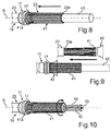
- a folding this EMC shield braid 39 which outside the cable sheath 23 was exposed. In this case, a bending around the cable sheath edge 23a takes place to the rear, so that, as shown in FIG Fig. 8 then the braid threads 41 rest against the outside 22 and extend axially.
- auxiliary tool namely, for example, the cone element or cone element 42
- This is designed as a hollow ring and can be pushed over the cable sheath 23.
- the braid threads 41 are oriented oriented parallel to the cable sheath 23 and extend in the context then also relatively evenly in the direction of the axis A.
- the cable 19 may have an already mentioned inner sheath 43, as shown in FIGS. 8 and 9 then exposed. This inner sheath 43 is then, if it is present, according to the further method step in Fig. 10 removed, so that the already mentioned wire strands 40 are exposed.
- six line strands are present here in the exemplary cable 19.
- the inner jacket 43 is removed over the length a3.
- the representation in Fig. 10 removed the previously mentioned filling material, so that the lead wires 40 are made completely exposed.
- the cable 19 also additionally has what is known as an extension cord, then it is also folded over in a then subsequent step, in particular, and connected to the EMC screen braid 39.
- both the clamping bush 11 and the clamping sleeve 10 in particular jointly and simultaneously pushed back in the opposite direction towards the cable sheath edge 23a, in particular until a front end or a leading edge 10c of the clamping sleeve 10 is on the same axial position as the cable sheath edge 23a.
- a radial fanning out of the braid threads 41 is automatically effected so that braided loops or braided loops 44 are formed in this intermediate manufacturing state.
- FIG. 14 pushed the shielding sleeve 9 from the exposed lead wires 40 forth on the cable 19. The sliding then takes place in the direction of the clamping bush 11 up to an end position of the shielding sleeve 9, as then in Fig. 2 also shown.
- the radially projecting mesh loops 44 are bent to the outside 10 a of the clamping sleeve 10 out, and by the geometric configurations of the shielding sleeve 9 and the clamping sleeve 10 is then already to Fig. 2 and Fig. 3 addressed EMC shield braid layer gap 31 generated in the then by this pushing the shielding sleeve 9 to its final position, as they then in Fig. 15 is shown, the double-layered design is generated automatically in this gap 31.
- the lead wires 40 are then stripped at the front end, and as shown in FIG Fig. 17 then the contacts 7 are applied to the stripped regions of the lead wires 40.
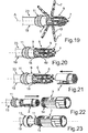
- the lead wires 40 are bent radially outward, in particular arranged in a star shape to one another, so that then the second insulating element or the second insulating body 6 can be applied ( Fig. 19 ).
- a respective stranded wire 40 is placed, which then as shown in FIG Fig. 20 in turn be folded inward and the lead wires are each embedded in a groove 8, in particular there are also clipped.
- the first insulating body 3 is pushed onto the second insulating body 6 and according to the further step in Fig. 22 then the connector housing 2 is applied.
- the connecting ring 13 is applied and connected to the connector housing 2, in particular screwed.
- a compression can be formed.
- a claw of the connecting portion 34 is generated in the inner side 24 a.
- an electrical connector 1 in which a cable 19 with an EMC shield braid 39 and at least one lead strand 40 with a cable end piece 35 is mounted in the connector housing 2.
- EMC shield braid 39 Surrounded by a cable sheath 23 EMC shield braid 39 is bent in the axial direction of the cable 19 over a partial length a3 on a cable sheath edge 23a backwards and with the cable sheath 23 in the axial direction overlapping and moved in the axial direction outside of the cable sheath 23.
- the part length a3 of the EMC shield braid 39 laid outside the cable sheath 23 is bent over again at least once after bending around the cable sheath edge 23a, so that the EMC shield braid 39 is formed at least two layers outside the cable sheath 23 in the radial direction.
- the partial lengths a3 before bending around the cable sheath edge 23a defined defined such that in the further manufacturing steps of the plug 1 from the bending of this partial length a3 to the cable sheath edge 23a a ablfitungsloses further in itself Bending the partial length a3 to produce oriented in the axial direction of the sub-descenders this part length a3 is performed.
- These partial descenders are defined by the generated layers of this partial length a3.
Landscapes
- Engineering & Computer Science (AREA)
- Manufacturing & Machinery (AREA)
- Details Of Connecting Devices For Male And Female Coupling (AREA)
- Manufacturing Of Electrical Connectors (AREA)
Priority Applications (1)
| Application Number | Priority Date | Filing Date | Title |
|---|---|---|---|
| EP17195187.4A EP3300174B1 (fr) | 2015-03-31 | 2016-03-24 | Fiche électrique |
Applications Claiming Priority (1)
| Application Number | Priority Date | Filing Date | Title |
|---|---|---|---|
| DE102015104958.9A DE102015104958B4 (de) | 2015-03-31 | 2015-03-31 | Elektrischer Stecker und Verfahren zum Herstellen eines elektrischen Steckers mit einer spezifischen EMV-Schirmanordnung |
Related Child Applications (2)
| Application Number | Title | Priority Date | Filing Date |
|---|---|---|---|
| EP17195187.4A Division EP3300174B1 (fr) | 2015-03-31 | 2016-03-24 | Fiche électrique |
| EP17195187.4A Division-Into EP3300174B1 (fr) | 2015-03-31 | 2016-03-24 | Fiche électrique |
Publications (3)
| Publication Number | Publication Date |
|---|---|
| EP3076485A2 true EP3076485A2 (fr) | 2016-10-05 |
| EP3076485A3 EP3076485A3 (fr) | 2017-01-04 |
| EP3076485B1 EP3076485B1 (fr) | 2019-01-23 |
Family
ID=55628900
Family Applications (2)
| Application Number | Title | Priority Date | Filing Date |
|---|---|---|---|
| EP16162240.2A Active EP3076485B1 (fr) | 2015-03-31 | 2016-03-24 | Connecteur electrique et procede de fabrication d'un connecteur electrique comprenant un agencement d'isolation cem |
| EP17195187.4A Active EP3300174B1 (fr) | 2015-03-31 | 2016-03-24 | Fiche électrique |
Family Applications After (1)
| Application Number | Title | Priority Date | Filing Date |
|---|---|---|---|
| EP17195187.4A Active EP3300174B1 (fr) | 2015-03-31 | 2016-03-24 | Fiche électrique |
Country Status (2)
| Country | Link |
|---|---|
| EP (2) | EP3076485B1 (fr) |
| DE (1) | DE102015104958B4 (fr) |
Cited By (5)
| Publication number | Priority date | Publication date | Assignee | Title |
|---|---|---|---|---|
| CN107768893A (zh) * | 2017-10-18 | 2018-03-06 | 中天科技装备电缆有限公司 | 一种轨道交通车辆通信连接器及其安装方法 |
| EP3547457A1 (fr) * | 2018-03-26 | 2019-10-02 | Yazaki Corporation | Connecteur et câble électrique doté d'un connecteur |
| CN111418116A (zh) * | 2018-01-08 | 2020-07-14 | 菲尼克斯电气公司 | 电缆线屏蔽件接触装置和电插接连接器 |
| CN115485936A (zh) * | 2020-04-24 | 2022-12-16 | 安格如股份公司 | 压接工具 |
| CN119560836A (zh) * | 2025-01-26 | 2025-03-04 | 东莞市民兴电缆有限公司 | 一种电缆连接设备及方法 |
Citations (2)
| Publication number | Priority date | Publication date | Assignee | Title |
|---|---|---|---|---|
| DE29916204U1 (de) | 1999-09-15 | 2000-01-05 | Intercontec GmbH, 94336 Hunderdorf | Kontaktierungseinrichtung für den Kabelschirm in elektrischen Steckverbindern |
| DE202012101656U1 (de) | 2012-05-04 | 2012-05-21 | Intercontec Pfeiffer Gmbh | Kabelverbindungsvorrichtung für ein Kabel |
Family Cites Families (10)
| Publication number | Priority date | Publication date | Assignee | Title |
|---|---|---|---|---|
| US3992773A (en) * | 1975-04-21 | 1976-11-23 | Grumman Aerospace Corporation | Magnetic forming process for joining electrical connectors and cables |
| EP0125760A1 (fr) * | 1983-04-13 | 1984-11-21 | AMP INCORPORATED (a New Jersey corporation) | Connecteur à broches ayant une enveloppe blindée |
| JPS61110977A (ja) * | 1984-11-05 | 1986-05-29 | 東光特殊電線株式会社 | 通信ケ−ブル結接部における遮へい体の製造方法 |
| DE29606708U1 (de) * | 1996-04-12 | 1996-07-04 | Dietzel Ges. m.b.H., Wien | Kontakthülse für abgeschirmte Kabel |
| JP3435036B2 (ja) * | 1997-08-29 | 2003-08-11 | 矢崎総業株式会社 | シールド電線の接続構造及び処理方法 |
| JP2005123072A (ja) * | 2003-10-17 | 2005-05-12 | Auto Network Gijutsu Kenkyusho:Kk | シールド用編組体の端末処理方法 |
| JP4316482B2 (ja) * | 2004-12-03 | 2009-08-19 | 矢崎総業株式会社 | シールド電線のアース処理方法及びアース処理構造 |
| JP4530890B2 (ja) * | 2005-03-23 | 2010-08-25 | 矢崎総業株式会社 | 同軸ケーブルの端末処理構造及び同軸ケーブル用シールド端子 |
| FR2929460B1 (fr) * | 2008-03-27 | 2010-04-23 | Fed Mogul Systems Prot Group | Dispositif de protection, notamment pour un element de connexion |
| JP5362270B2 (ja) * | 2008-07-03 | 2013-12-11 | 矢崎総業株式会社 | シールド電線、及び該シールド電線の編組端末処理方法、並びに、編組端末処理装置 |
-
2015
- 2015-03-31 DE DE102015104958.9A patent/DE102015104958B4/de active Active
-
2016
- 2016-03-24 EP EP16162240.2A patent/EP3076485B1/fr active Active
- 2016-03-24 EP EP17195187.4A patent/EP3300174B1/fr active Active
Patent Citations (2)
| Publication number | Priority date | Publication date | Assignee | Title |
|---|---|---|---|---|
| DE29916204U1 (de) | 1999-09-15 | 2000-01-05 | Intercontec GmbH, 94336 Hunderdorf | Kontaktierungseinrichtung für den Kabelschirm in elektrischen Steckverbindern |
| DE202012101656U1 (de) | 2012-05-04 | 2012-05-21 | Intercontec Pfeiffer Gmbh | Kabelverbindungsvorrichtung für ein Kabel |
Cited By (9)
| Publication number | Priority date | Publication date | Assignee | Title |
|---|---|---|---|---|
| CN107768893A (zh) * | 2017-10-18 | 2018-03-06 | 中天科技装备电缆有限公司 | 一种轨道交通车辆通信连接器及其安装方法 |
| CN111418116A (zh) * | 2018-01-08 | 2020-07-14 | 菲尼克斯电气公司 | 电缆线屏蔽件接触装置和电插接连接器 |
| CN111418116B (zh) * | 2018-01-08 | 2021-07-23 | 菲尼克斯电气公司 | 电缆线屏蔽件接触装置和电插接连接器 |
| EP3547457A1 (fr) * | 2018-03-26 | 2019-10-02 | Yazaki Corporation | Connecteur et câble électrique doté d'un connecteur |
| CN110364886A (zh) * | 2018-03-26 | 2019-10-22 | 矢崎总业株式会社 | 连接器以及带连接器的电线 |
| US10756493B2 (en) | 2018-03-26 | 2020-08-25 | Yazaki Corporation | Connector and electric wire with connector |
| CN115485936A (zh) * | 2020-04-24 | 2022-12-16 | 安格如股份公司 | 压接工具 |
| CN119560836A (zh) * | 2025-01-26 | 2025-03-04 | 东莞市民兴电缆有限公司 | 一种电缆连接设备及方法 |
| CN119560836B (zh) * | 2025-01-26 | 2025-06-03 | 东莞市民兴电缆有限公司 | 一种电缆连接设备及方法 |
Also Published As
| Publication number | Publication date |
|---|---|
| DE102015104958B4 (de) | 2016-11-03 |
| EP3300174B1 (fr) | 2019-08-07 |
| DE102015104958A1 (de) | 2016-10-06 |
| EP3076485B1 (fr) | 2019-01-23 |
| EP3300174A1 (fr) | 2018-03-28 |
| EP3076485A3 (fr) | 2017-01-04 |
Similar Documents
| Publication | Publication Date | Title |
|---|---|---|
| EP3076485B1 (fr) | Connecteur electrique et procede de fabrication d'un connecteur electrique comprenant un agencement d'isolation cem | |
| DE19634065B4 (de) | Spleißvorrichtung und Verfahren zur Herstellung einer Spleißstelle für abgeschirmte Kabel | |
| DE69301156T2 (de) | Mehrzweigige abgeschirmte Verbindung | |
| EP3281260B1 (fr) | Méthode pour assemblage d'un connecteur électrique | |
| EP3403297A1 (fr) | Douille de contact radial | |
| EP3711119B1 (fr) | Dispositif électrique de mise en contact de blindage de câble et connecteur électrique | |
| DE19613228B4 (de) | Elektrische Steckverbindung, insbesondere Steckerteil für eine elektrische Steckverbindung | |
| DE19848343A1 (de) | Aufbau eines Endabschnittes eines abgeschirmten Kabels und Verfahren zur Herstellung desselben | |
| EP3327868B1 (fr) | Connecteur électrique pour un câble électrique multi-fils | |
| EP3595101B1 (fr) | Connecteur enfichable électrique pour un câble électrique multi-fils | |
| EP4055674B1 (fr) | Procédé et dispositif de traitement d'un câble électrique | |
| EP3952035B1 (fr) | Procédé et dispositif d'usinage d'une extrémité de câble, ainsi que câble ainsi usiné | |
| EP2530785A1 (fr) | Décharge de traction de câble et connecteur à fiche avec décharge de traction de câble | |
| DE102015219800A1 (de) | Mehradriges geschirmtes Kabel und Verfahren zur Herstellung eines derartigen Kabels | |
| EP2660939B1 (fr) | Dispositif de liaison de câble pour un câble | |
| EP3528351B1 (fr) | Connecteur électrique pour un câble électrique multi-fils | |
| DE102018218364B4 (de) | Verteilergehäuse für einen Verteiler, Verteiler, Verfahren zur Herstellung eines Verteilers und Verfahren zur Herstellung eines Verteilergehäuses | |
| EP1667284B1 (fr) | Dispositif de contact pour un blindage de câble | |
| WO2025098804A1 (fr) | Passe-fil fixé à une gaine de câble au moyen d'un soudage au laser | |
| EP2571102B1 (fr) | Dispositif de mise en contact de la gaine d'un câble coaxial | |
| EP1465312A2 (fr) | Raccordement de câbles haute tension | |
| DE10048200A1 (de) | Kabelverbindung | |
| WO2009115374A1 (fr) | Entrée de câble |
Legal Events
| Date | Code | Title | Description |
|---|---|---|---|
| PUAI | Public reference made under article 153(3) epc to a published international application that has entered the european phase |
Free format text: ORIGINAL CODE: 0009012 |
|
| AK | Designated contracting states |
Kind code of ref document: A2 Designated state(s): AL AT BE BG CH CY CZ DE DK EE ES FI FR GB GR HR HU IE IS IT LI LT LU LV MC MK MT NL NO PL PT RO RS SE SI SK SM TR |
|
| AX | Request for extension of the european patent |
Extension state: BA ME |
|
| PUAL | Search report despatched |
Free format text: ORIGINAL CODE: 0009013 |
|
| AK | Designated contracting states |
Kind code of ref document: A3 Designated state(s): AL AT BE BG CH CY CZ DE DK EE ES FI FR GB GR HR HU IE IS IT LI LT LU LV MC MK MT NL NO PL PT RO RS SE SI SK SM TR |
|
| AX | Request for extension of the european patent |
Extension state: BA ME |
|
| RIC1 | Information provided on ipc code assigned before grant |
Ipc: H01R 9/05 20060101ALI20161130BHEP Ipc: H01R 9/03 20060101AFI20161130BHEP Ipc: H01R 13/512 20060101ALN20161130BHEP Ipc: H01R 43/28 20060101ALI20161130BHEP |
|
| STAA | Information on the status of an ep patent application or granted ep patent |
Free format text: STATUS: REQUEST FOR EXAMINATION WAS MADE |
|
| 17P | Request for examination filed |
Effective date: 20170330 |
|
| RBV | Designated contracting states (corrected) |
Designated state(s): AL AT BE BG CH CY CZ DE DK EE ES FI FR GB GR HR HU IE IS IT LI LT LU LV MC MK MT NL NO PL PT RO RS SE SI SK SM TR |
|
| STAA | Information on the status of an ep patent application or granted ep patent |
Free format text: STATUS: EXAMINATION IS IN PROGRESS |
|
| 17Q | First examination report despatched |
Effective date: 20171002 |
|
| REG | Reference to a national code |
Ref country code: HK Ref legal event code: DE Ref document number: 1229073 Country of ref document: HK |
|
| RAP1 | Party data changed (applicant data changed or rights of an application transferred) |
Owner name: TE CONNECTIVITY INDUSTRIAL GMBH |
|
| GRAP | Despatch of communication of intention to grant a patent |
Free format text: ORIGINAL CODE: EPIDOSNIGR1 |
|
| STAA | Information on the status of an ep patent application or granted ep patent |
Free format text: STATUS: GRANT OF PATENT IS INTENDED |
|
| RIC1 | Information provided on ipc code assigned before grant |
Ipc: H01R 9/03 20060101AFI20180829BHEP Ipc: H01R 13/512 20060101ALN20180829BHEP Ipc: H01R 43/28 20060101ALI20180829BHEP Ipc: H01R 9/05 20060101ALI20180829BHEP |
|
| INTG | Intention to grant announced |
Effective date: 20180919 |
|
| GRAS | Grant fee paid |
Free format text: ORIGINAL CODE: EPIDOSNIGR3 |
|
| GRAA | (expected) grant |
Free format text: ORIGINAL CODE: 0009210 |
|
| STAA | Information on the status of an ep patent application or granted ep patent |
Free format text: STATUS: THE PATENT HAS BEEN GRANTED |
|
| AK | Designated contracting states |
Kind code of ref document: B1 Designated state(s): AL AT BE BG CH CY CZ DE DK EE ES FI FR GB GR HR HU IE IS IT LI LT LU LV MC MK MT NL NO PL PT RO RS SE SI SK SM TR |
|
| REG | Reference to a national code |
Ref country code: GB Ref legal event code: FG4D Free format text: NOT ENGLISH |
|
| REG | Reference to a national code |
Ref country code: CH Ref legal event code: EP |
|
| REG | Reference to a national code |
Ref country code: AT Ref legal event code: REF Ref document number: 1092187 Country of ref document: AT Kind code of ref document: T Effective date: 20190215 |
|
| REG | Reference to a national code |
Ref country code: IE Ref legal event code: FG4D Free format text: LANGUAGE OF EP DOCUMENT: GERMAN |
|
| REG | Reference to a national code |
Ref country code: DE Ref legal event code: R096 Ref document number: 502016003175 Country of ref document: DE |
|
| REG | Reference to a national code |
Ref country code: NL Ref legal event code: MP Effective date: 20190123 |
|
| PG25 | Lapsed in a contracting state [announced via postgrant information from national office to epo] |
Ref country code: NL Free format text: LAPSE BECAUSE OF FAILURE TO SUBMIT A TRANSLATION OF THE DESCRIPTION OR TO PAY THE FEE WITHIN THE PRESCRIBED TIME-LIMIT Effective date: 20190123 |
|
| PG25 | Lapsed in a contracting state [announced via postgrant information from national office to epo] |
Ref country code: FI Free format text: LAPSE BECAUSE OF FAILURE TO SUBMIT A TRANSLATION OF THE DESCRIPTION OR TO PAY THE FEE WITHIN THE PRESCRIBED TIME-LIMIT Effective date: 20190123 Ref country code: LT Free format text: LAPSE BECAUSE OF FAILURE TO SUBMIT A TRANSLATION OF THE DESCRIPTION OR TO PAY THE FEE WITHIN THE PRESCRIBED TIME-LIMIT Effective date: 20190123 Ref country code: NO Free format text: LAPSE BECAUSE OF FAILURE TO SUBMIT A TRANSLATION OF THE DESCRIPTION OR TO PAY THE FEE WITHIN THE PRESCRIBED TIME-LIMIT Effective date: 20190423 Ref country code: PL Free format text: LAPSE BECAUSE OF FAILURE TO SUBMIT A TRANSLATION OF THE DESCRIPTION OR TO PAY THE FEE WITHIN THE PRESCRIBED TIME-LIMIT Effective date: 20190123 Ref country code: SE Free format text: LAPSE BECAUSE OF FAILURE TO SUBMIT A TRANSLATION OF THE DESCRIPTION OR TO PAY THE FEE WITHIN THE PRESCRIBED TIME-LIMIT Effective date: 20190123 Ref country code: PT Free format text: LAPSE BECAUSE OF FAILURE TO SUBMIT A TRANSLATION OF THE DESCRIPTION OR TO PAY THE FEE WITHIN THE PRESCRIBED TIME-LIMIT Effective date: 20190523 Ref country code: ES Free format text: LAPSE BECAUSE OF FAILURE TO SUBMIT A TRANSLATION OF THE DESCRIPTION OR TO PAY THE FEE WITHIN THE PRESCRIBED TIME-LIMIT Effective date: 20190123 |
|
| PG25 | Lapsed in a contracting state [announced via postgrant information from national office to epo] |
Ref country code: LV Free format text: LAPSE BECAUSE OF FAILURE TO SUBMIT A TRANSLATION OF THE DESCRIPTION OR TO PAY THE FEE WITHIN THE PRESCRIBED TIME-LIMIT Effective date: 20190123 Ref country code: RS Free format text: LAPSE BECAUSE OF FAILURE TO SUBMIT A TRANSLATION OF THE DESCRIPTION OR TO PAY THE FEE WITHIN THE PRESCRIBED TIME-LIMIT Effective date: 20190123 Ref country code: IS Free format text: LAPSE BECAUSE OF FAILURE TO SUBMIT A TRANSLATION OF THE DESCRIPTION OR TO PAY THE FEE WITHIN THE PRESCRIBED TIME-LIMIT Effective date: 20190523 Ref country code: BG Free format text: LAPSE BECAUSE OF FAILURE TO SUBMIT A TRANSLATION OF THE DESCRIPTION OR TO PAY THE FEE WITHIN THE PRESCRIBED TIME-LIMIT Effective date: 20190423 Ref country code: HR Free format text: LAPSE BECAUSE OF FAILURE TO SUBMIT A TRANSLATION OF THE DESCRIPTION OR TO PAY THE FEE WITHIN THE PRESCRIBED TIME-LIMIT Effective date: 20190123 Ref country code: GR Free format text: LAPSE BECAUSE OF FAILURE TO SUBMIT A TRANSLATION OF THE DESCRIPTION OR TO PAY THE FEE WITHIN THE PRESCRIBED TIME-LIMIT Effective date: 20190424 |
|
| REG | Reference to a national code |
Ref country code: DE Ref legal event code: R097 Ref document number: 502016003175 Country of ref document: DE |
|
| PG25 | Lapsed in a contracting state [announced via postgrant information from national office to epo] |
Ref country code: DK Free format text: LAPSE BECAUSE OF FAILURE TO SUBMIT A TRANSLATION OF THE DESCRIPTION OR TO PAY THE FEE WITHIN THE PRESCRIBED TIME-LIMIT Effective date: 20190123 Ref country code: EE Free format text: LAPSE BECAUSE OF FAILURE TO SUBMIT A TRANSLATION OF THE DESCRIPTION OR TO PAY THE FEE WITHIN THE PRESCRIBED TIME-LIMIT Effective date: 20190123 Ref country code: MC Free format text: LAPSE BECAUSE OF FAILURE TO SUBMIT A TRANSLATION OF THE DESCRIPTION OR TO PAY THE FEE WITHIN THE PRESCRIBED TIME-LIMIT Effective date: 20190123 Ref country code: SK Free format text: LAPSE BECAUSE OF FAILURE TO SUBMIT A TRANSLATION OF THE DESCRIPTION OR TO PAY THE FEE WITHIN THE PRESCRIBED TIME-LIMIT Effective date: 20190123 Ref country code: AL Free format text: LAPSE BECAUSE OF FAILURE TO SUBMIT A TRANSLATION OF THE DESCRIPTION OR TO PAY THE FEE WITHIN THE PRESCRIBED TIME-LIMIT Effective date: 20190123 Ref country code: IT Free format text: LAPSE BECAUSE OF FAILURE TO SUBMIT A TRANSLATION OF THE DESCRIPTION OR TO PAY THE FEE WITHIN THE PRESCRIBED TIME-LIMIT Effective date: 20190123 Ref country code: RO Free format text: LAPSE BECAUSE OF FAILURE TO SUBMIT A TRANSLATION OF THE DESCRIPTION OR TO PAY THE FEE WITHIN THE PRESCRIBED TIME-LIMIT Effective date: 20190123 Ref country code: CZ Free format text: LAPSE BECAUSE OF FAILURE TO SUBMIT A TRANSLATION OF THE DESCRIPTION OR TO PAY THE FEE WITHIN THE PRESCRIBED TIME-LIMIT Effective date: 20190123 |
|
| REG | Reference to a national code |
Ref country code: CH Ref legal event code: PL |
|
| PG25 | Lapsed in a contracting state [announced via postgrant information from national office to epo] |
Ref country code: SM Free format text: LAPSE BECAUSE OF FAILURE TO SUBMIT A TRANSLATION OF THE DESCRIPTION OR TO PAY THE FEE WITHIN THE PRESCRIBED TIME-LIMIT Effective date: 20190123 Ref country code: LU Free format text: LAPSE BECAUSE OF NON-PAYMENT OF DUE FEES Effective date: 20190324 |
|
| PLBE | No opposition filed within time limit |
Free format text: ORIGINAL CODE: 0009261 |
|
| STAA | Information on the status of an ep patent application or granted ep patent |
Free format text: STATUS: NO OPPOSITION FILED WITHIN TIME LIMIT |
|
| REG | Reference to a national code |
Ref country code: BE Ref legal event code: MM Effective date: 20190331 |
|
| 26N | No opposition filed |
Effective date: 20191024 |
|
| PG25 | Lapsed in a contracting state [announced via postgrant information from national office to epo] |
Ref country code: CH Free format text: LAPSE BECAUSE OF NON-PAYMENT OF DUE FEES Effective date: 20190331 Ref country code: LI Free format text: LAPSE BECAUSE OF NON-PAYMENT OF DUE FEES Effective date: 20190331 Ref country code: IE Free format text: LAPSE BECAUSE OF NON-PAYMENT OF DUE FEES Effective date: 20190324 |
|
| PG25 | Lapsed in a contracting state [announced via postgrant information from national office to epo] |
Ref country code: BE Free format text: LAPSE BECAUSE OF NON-PAYMENT OF DUE FEES Effective date: 20190331 Ref country code: SI Free format text: LAPSE BECAUSE OF FAILURE TO SUBMIT A TRANSLATION OF THE DESCRIPTION OR TO PAY THE FEE WITHIN THE PRESCRIBED TIME-LIMIT Effective date: 20190123 |
|
| PG25 | Lapsed in a contracting state [announced via postgrant information from national office to epo] |
Ref country code: TR Free format text: LAPSE BECAUSE OF FAILURE TO SUBMIT A TRANSLATION OF THE DESCRIPTION OR TO PAY THE FEE WITHIN THE PRESCRIBED TIME-LIMIT Effective date: 20190123 |
|
| PG25 | Lapsed in a contracting state [announced via postgrant information from national office to epo] |
Ref country code: MT Free format text: LAPSE BECAUSE OF FAILURE TO SUBMIT A TRANSLATION OF THE DESCRIPTION OR TO PAY THE FEE WITHIN THE PRESCRIBED TIME-LIMIT Effective date: 20190123 |
|
| PG25 | Lapsed in a contracting state [announced via postgrant information from national office to epo] |
Ref country code: CY Free format text: LAPSE BECAUSE OF FAILURE TO SUBMIT A TRANSLATION OF THE DESCRIPTION OR TO PAY THE FEE WITHIN THE PRESCRIBED TIME-LIMIT Effective date: 20190123 |
|
| PG25 | Lapsed in a contracting state [announced via postgrant information from national office to epo] |
Ref country code: HU Free format text: LAPSE BECAUSE OF FAILURE TO SUBMIT A TRANSLATION OF THE DESCRIPTION OR TO PAY THE FEE WITHIN THE PRESCRIBED TIME-LIMIT; INVALID AB INITIO Effective date: 20160324 |
|
| REG | Reference to a national code |
Ref country code: AT Ref legal event code: MM01 Ref document number: 1092187 Country of ref document: AT Kind code of ref document: T Effective date: 20210324 |
|
| PG25 | Lapsed in a contracting state [announced via postgrant information from national office to epo] |
Ref country code: MK Free format text: LAPSE BECAUSE OF FAILURE TO SUBMIT A TRANSLATION OF THE DESCRIPTION OR TO PAY THE FEE WITHIN THE PRESCRIBED TIME-LIMIT Effective date: 20190123 |
|
| PG25 | Lapsed in a contracting state [announced via postgrant information from national office to epo] |
Ref country code: AT Free format text: LAPSE BECAUSE OF NON-PAYMENT OF DUE FEES Effective date: 20210324 |
|
| PGFP | Annual fee paid to national office [announced via postgrant information from national office to epo] |
Ref country code: FR Payment date: 20251231 Year of fee payment: 11 |
|
| PGFP | Annual fee paid to national office [announced via postgrant information from national office to epo] |
Ref country code: GB Payment date: 20260106 Year of fee payment: 11 |
|
| PGFP | Annual fee paid to national office [announced via postgrant information from national office to epo] |
Ref country code: DE Payment date: 20260102 Year of fee payment: 11 |