EP3077135B1 - Machine-outil pouvant être entraînée en oscillation - Google Patents
Machine-outil pouvant être entraînée en oscillation Download PDFInfo
- Publication number
- EP3077135B1 EP3077135B1 EP14796511.5A EP14796511A EP3077135B1 EP 3077135 B1 EP3077135 B1 EP 3077135B1 EP 14796511 A EP14796511 A EP 14796511A EP 3077135 B1 EP3077135 B1 EP 3077135B1
- Authority
- EP
- European Patent Office
- Prior art keywords
- machine tool
- tool according
- rotary
- fluid
- tool spindle
- Prior art date
- Legal status (The legal status is an assumption and is not a legal conclusion. Google has not performed a legal analysis and makes no representation as to the accuracy of the status listed.)
- Active
Links
Images

Classifications
-
- B—PERFORMING OPERATIONS; TRANSPORTING
- B25—HAND TOOLS; PORTABLE POWER-DRIVEN TOOLS; MANIPULATORS
- B25F—COMBINATION OR MULTI-PURPOSE TOOLS NOT OTHERWISE PROVIDED FOR; DETAILS OR COMPONENTS OF PORTABLE POWER-DRIVEN TOOLS NOT PARTICULARLY RELATED TO THE OPERATIONS PERFORMED AND NOT OTHERWISE PROVIDED FOR
- B25F5/00—Details or components of portable power-driven tools not particularly related to the operations performed and not otherwise provided for
- B25F5/005—Hydraulic driving means
-
- B—PERFORMING OPERATIONS; TRANSPORTING
- B23—MACHINE TOOLS; METAL-WORKING NOT OTHERWISE PROVIDED FOR
- B23D—PLANING; SLOTTING; SHEARING; BROACHING; SAWING; FILING; SCRAPING; LIKE OPERATIONS FOR WORKING METAL BY REMOVING MATERIAL, NOT OTHERWISE PROVIDED FOR
- B23D47/00—Sawing machines or sawing devices working with circular saw blades, characterised only by constructional features of particular parts
- B23D47/12—Sawing machines or sawing devices working with circular saw blades, characterised only by constructional features of particular parts of drives for circular saw blades
-
- B—PERFORMING OPERATIONS; TRANSPORTING
- B23—MACHINE TOOLS; METAL-WORKING NOT OTHERWISE PROVIDED FOR
- B23Q—DETAILS, COMPONENTS, OR ACCESSORIES FOR MACHINE TOOLS, e.g. ARRANGEMENTS FOR COPYING OR CONTROLLING; MACHINE TOOLS IN GENERAL CHARACTERISED BY THE CONSTRUCTION OF PARTICULAR DETAILS OR COMPONENTS; COMBINATIONS OR ASSOCIATIONS OF METAL-WORKING MACHINES, NOT DIRECTED TO A PARTICULAR RESULT
- B23Q5/00—Driving or feeding mechanisms; Control arrangements therefor
- B23Q5/02—Driving main working members
- B23Q5/027—Driving main working members reciprocating members
-
- B—PERFORMING OPERATIONS; TRANSPORTING
- B23—MACHINE TOOLS; METAL-WORKING NOT OTHERWISE PROVIDED FOR
- B23Q—DETAILS, COMPONENTS, OR ACCESSORIES FOR MACHINE TOOLS, e.g. ARRANGEMENTS FOR COPYING OR CONTROLLING; MACHINE TOOLS IN GENERAL CHARACTERISED BY THE CONSTRUCTION OF PARTICULAR DETAILS OR COMPONENTS; COMBINATIONS OR ASSOCIATIONS OF METAL-WORKING MACHINES, NOT DIRECTED TO A PARTICULAR RESULT
- B23Q5/00—Driving or feeding mechanisms; Control arrangements therefor
- B23Q5/02—Driving main working members
- B23Q5/04—Driving main working members rotary shafts, e.g. working-spindles
- B23Q5/06—Driving main working members rotary shafts, e.g. working-spindles driven essentially by fluid pressure or pneumatic power
-
- B—PERFORMING OPERATIONS; TRANSPORTING
- B24—GRINDING; POLISHING
- B24B—MACHINES, DEVICES, OR PROCESSES FOR GRINDING OR POLISHING; DRESSING OR CONDITIONING OF ABRADING SURFACES; FEEDING OF GRINDING, POLISHING, OR LAPPING AGENTS
- B24B23/00—Portable grinding machines, e.g. hand-guided; Accessories therefor
- B24B23/04—Portable grinding machines, e.g. hand-guided; Accessories therefor with oscillating grinding tools; Accessories therefor
- B24B23/043—Portable grinding machines, e.g. hand-guided; Accessories therefor with oscillating grinding tools; Accessories therefor reciprocatingly driven by a pneumatic or hydraulic piston
-
- B—PERFORMING OPERATIONS; TRANSPORTING
- B24—GRINDING; POLISHING
- B24B—MACHINES, DEVICES, OR PROCESSES FOR GRINDING OR POLISHING; DRESSING OR CONDITIONING OF ABRADING SURFACES; FEEDING OF GRINDING, POLISHING, OR LAPPING AGENTS
- B24B41/00—Component parts such as frames, beds, carriages, headstocks
- B24B41/007—Weight compensation; Temperature compensation; Vibration damping
-
- B—PERFORMING OPERATIONS; TRANSPORTING
- B24—GRINDING; POLISHING
- B24B—MACHINES, DEVICES, OR PROCESSES FOR GRINDING OR POLISHING; DRESSING OR CONDITIONING OF ABRADING SURFACES; FEEDING OF GRINDING, POLISHING, OR LAPPING AGENTS
- B24B47/00—Drives or gearings; Equipment therefor
- B24B47/10—Drives or gearings; Equipment therefor for rotating or reciprocating working-spindles carrying grinding wheels or workpieces
- B24B47/12—Drives or gearings; Equipment therefor for rotating or reciprocating working-spindles carrying grinding wheels or workpieces by mechanical gearing or electric power
-
- B—PERFORMING OPERATIONS; TRANSPORTING
- B24—GRINDING; POLISHING
- B24B—MACHINES, DEVICES, OR PROCESSES FOR GRINDING OR POLISHING; DRESSING OR CONDITIONING OF ABRADING SURFACES; FEEDING OF GRINDING, POLISHING, OR LAPPING AGENTS
- B24B47/00—Drives or gearings; Equipment therefor
- B24B47/10—Drives or gearings; Equipment therefor for rotating or reciprocating working-spindles carrying grinding wheels or workpieces
- B24B47/14—Drives or gearings; Equipment therefor for rotating or reciprocating working-spindles carrying grinding wheels or workpieces by liquid or gas pressure
-
- B—PERFORMING OPERATIONS; TRANSPORTING
- B24—GRINDING; POLISHING
- B24B—MACHINES, DEVICES, OR PROCESSES FOR GRINDING OR POLISHING; DRESSING OR CONDITIONING OF ABRADING SURFACES; FEEDING OF GRINDING, POLISHING, OR LAPPING AGENTS
- B24B47/00—Drives or gearings; Equipment therefor
- B24B47/10—Drives or gearings; Equipment therefor for rotating or reciprocating working-spindles carrying grinding wheels or workpieces
- B24B47/16—Drives or gearings; Equipment therefor for rotating or reciprocating working-spindles carrying grinding wheels or workpieces performing a reciprocating movement, e.g. during which the sense of rotation of the working-spindle is reversed
-
- B—PERFORMING OPERATIONS; TRANSPORTING
- B26—HAND CUTTING TOOLS; CUTTING; SEVERING
- B26D—CUTTING; DETAILS COMMON TO MACHINES FOR PERFORATING, PUNCHING, CUTTING-OUT, STAMPING-OUT OR SEVERING
- B26D5/00—Arrangements for operating and controlling machines or devices for cutting, cutting-out, stamping-out, punching, perforating, or severing by means other than cutting
- B26D5/08—Means for actuating the cutting member to effect the cut
- B26D5/12—Fluid-pressure means
-
- E—FIXED CONSTRUCTIONS
- E01—CONSTRUCTION OF ROADS, RAILWAYS, OR BRIDGES
- E01C—CONSTRUCTION OF, OR SURFACES FOR, ROADS, SPORTS GROUNDS, OR THE LIKE; MACHINES OR AUXILIARY TOOLS FOR CONSTRUCTION OR REPAIR
- E01C23/00—Auxiliary devices or arrangements for constructing, repairing, reconditioning, or taking-up road or like surfaces
- E01C23/06—Devices or arrangements for working the finished surface; Devices for repairing or reconditioning the surface of damaged paving; Recycling in place or on the road
- E01C23/08—Devices or arrangements for working the finished surface; Devices for repairing or reconditioning the surface of damaged paving; Recycling in place or on the road for roughening or patterning; for removing the surface down to a predetermined depth high spots or material bonded to the surface, e.g. markings; for maintaining earth roads, clay courts or like surfaces by means of surface working tools, e.g. scarifiers, levelling blades
- E01C23/085—Devices or arrangements for working the finished surface; Devices for repairing or reconditioning the surface of damaged paving; Recycling in place or on the road for roughening or patterning; for removing the surface down to a predetermined depth high spots or material bonded to the surface, e.g. markings; for maintaining earth roads, clay courts or like surfaces by means of surface working tools, e.g. scarifiers, levelling blades using power-driven tools, e.g. vibratory tools
- E01C23/088—Rotary tools, e.g. milling drums
-
- F—MECHANICAL ENGINEERING; LIGHTING; HEATING; WEAPONS; BLASTING
- F15—FLUID-PRESSURE ACTUATORS; HYDRAULICS OR PNEUMATICS IN GENERAL
- F15B—SYSTEMS ACTING BY MEANS OF FLUIDS IN GENERAL; FLUID-PRESSURE ACTUATORS, e.g. SERVOMOTORS; DETAILS OF FLUID-PRESSURE SYSTEMS, NOT OTHERWISE PROVIDED FOR
- F15B15/00—Fluid-actuated devices for displacing a member from one position to another; Gearing associated therewith
- F15B15/08—Characterised by the construction of the motor unit
- F15B15/12—Characterised by the construction of the motor unit of the oscillating-vane or curved-cylinder type
-
- E—FIXED CONSTRUCTIONS
- E01—CONSTRUCTION OF ROADS, RAILWAYS, OR BRIDGES
- E01C—CONSTRUCTION OF, OR SURFACES FOR, ROADS, SPORTS GROUNDS, OR THE LIKE; MACHINES OR AUXILIARY TOOLS FOR CONSTRUCTION OR REPAIR
- E01C2301/00—Machine characteristics, parts or accessories not otherwise provided for
- E01C2301/30—Cabin details
Definitions
- the invention relates to a machine tool that can be driven in an oscillating manner with a drive motor and with a tool spindle that is pivotably mounted about its longitudinal axis and can be driven in a rotationally oscillating manner about its longitudinal axis.
- Such oscillatingly drivable machine tools are known in a variety of designs. They are driven by a mechanical oscillating gear, which converts the rotating drive movement of a drive motor into a rotary oscillating drive movement of the tool spindle around its longitudinal axis.
- an eccentric is provided for this purpose, which interacts with an eccentric fork for the oscillating drive of the tool spindle.
- the eccentric is driven in rotation by an eccentric shaft that is arranged parallel to the tool spindle.
- a machine tool that can be driven in an oscillating manner has a drive motor with a motor shaft, and a tool spindle that can be driven in a rotationally oscillating manner about its longitudinal axis, a coupling member that can be driven in rotation by the motor shaft and has a closed guide surface that runs around a guide axis, the guide surface being connected via transmission means at least one driver is coupled to its drive, wherein the at least one driver is held movably relative to the work spindle and engages in a peripheral region of the work spindle in order to drive it in a rotationally oscillating manner.
- Such mechanical oscillation gears are available in numerous designs in order to convert the rotating drive movement of a motor shaft into the rotationally oscillating movement of the tool spindle.
- the drive movement oscillating back and forth is converted by means of a ratchet mechanism into a drive movement of the milling head which oscillates intermittently in a preferred direction.
- the well-known machine tool is specially designed for use with a milling head, but not for generating a rotationally oscillating Drive movement of a tool spindle, as required for oscillating machine tools.
- a rotary vane motor which has symmetrically arranged rotary vanes which are formed as rotary piston fingers.
- Another rotary vane motor is from the DE 20 2012 101 137 U1 known in which the rotary vane motor drives a hollow-cylindrical rotary actuator outer part in an oscillating manner in order to drive another component, for example a rudder of a seagoing vessel or a push rod, with an outer part extension extending radially therefrom.
- the invention is based on the object of improving an oscillatingly drivable machine tool of the type mentioned at the outset in such a way that a rotationally oscillating drive of the tool spindle is made possible in the simplest and most reliable manner possible, even under high mechanical loads, and in particular vibrations are prevented.
- This object is achieved by a machine tool that can be driven in an oscillating manner according to claim 1 .
- the object of the invention is achieved in this way.
- the rotary vane motor enables the pulsating fluid energy to be converted directly into an oscillating movement of the tool spindle without the need for a mechanical gear.
- the tool spindle is driven in a rotationally oscillating manner at a frequency of 5,000 to 30,000 oscillations per minute and with a pivoting angle of ⁇ 1° to ⁇ 5′ (from reversal point to reversal point).
- a particular advantage of the above arrangement is that the essential parameters of the oscillating drive can be adjusted by the respective dimensioning of the hydraulic device, ie in particular the oscillation angle, the angular velocity, the angular acceleration and the torque generated.
- the rotary vane motor has symmetrically arranged rotary vanes which are arranged at defined angular distances from one another.
- the rotary vanes are designed as rotary piston fingers on the tool spindle.
- the tool spindle runs in a bush correspondingly shaped as a counterpart.
- fluid chambers are formed on both sides of each rotary piston finger with the bush, which are coupled to oppositely pressure-pulsating connections of the hydraulic generator.
- the bushing is made of a bronze alloy and the tool spindle is preferably made of steel.
- the rotary vane motor has four rotary piston fingers which are angularly offset by 90° to one another.
- the hydraulic generator is designed as a displacement pump with a linear piston, which is driven by a motor shaft of the drive motor via an eccentric.
- pressure chambers are formed at the two ends of the linear piston, in which the oppositely pulsating fluid energy is generated.
- each of the two pressure chambers is preferably coupled via a distributor with associated bores on the bush in order to supply the fluid chambers on both sides of the rotary piston fingers with fluid pulsating in opposite directions.
- a pressurized hydraulic fluid reservoir is provided, which is coupled to the hydraulic generator via check valves.
- the hydraulic fluid reservoir can be designed as a chamber of a cylinder.
- the corresponding pressure is applied by a spring that acts on the piston that can be moved in the cylinder.
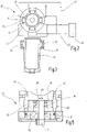
- the machine tool 10 has a tool spindle 34 which is pivotably mounted about its longitudinal axis 35 by means of two roller bearings 26, 28 in the housing.
- the tool spindle 34 is designed as a hollow spindle, with a ram 25 accommodated therein, braced against the force of a spring (not shown), on which a holding element 27 is fixed.
- the plunger 25 can by means of a clamping lever 23 can be displaced axially against the preload of the spring via an eccentric 24 acting on the plunger 25, for which purpose the clamping lever 23 from 1 clamping position shown is pivoted forward into a release position.
- the clamping element 37 is again inserted through an associated recess of the tool into the tool spindle 34 until the toothing 39 engages in the holding element 37, and the clamping lever 23 returns to its clamping position according to FIG 1 emotional.
- the tool spindle 34 can be driven about its longitudinal axis 35 with a high frequency and in the range of about 5,000 to 30,000 oscillations per minute and a small pivoting angle in the range of about ⁇ 1° to ⁇ 5° (from reversal point to reversal point).
- the frequency preferably corresponds to the speed of the drive motor 14 used and is approximately 333 Hz at 20,000 revolutions per minute.
- the pivoting angle from reversal point to reversal point is preferably ⁇ 2.5°.
- a hydraulic generator is driven by the engine 14, which in 1 is only indicated with the number 22.
- the hydraulic generator 22 converts the oscillating fluid energy via a hydraulic motor 30, which is coupled to the tool spindle 34, into a rotationally oscillating drive movement of the tool spindle 34 about its longitudinal axis 35.
- In 2 is the hydraulic motor 30 according to FIG 1 shown schematically. It is a symmetrically designed rotary vane pivoting vane motor (rotary vane motor for short) 30, which has four rotary vanes 38, which are arranged at an angle of 90° to one another and are formed on the tool spindle 34 on the outside. Associated with each rotary finger 38 are two adjacent fluid chambers 40, 41 formed between the tool spindle 34 and the surrounding sleeve 32 in which the tool spindle 34 rides in that area.
- rotary vane pivoting vane motor rotary vane motor for short
- adjoining fluid chambers 40, 41 are formed on both sides of each rotary piston finger 38.
- eight fluid chambers 40, 41 are formed around the circumference of the tool spindle 34, distributed at defined angular intervals.
- the fluid chambers 40 are coupled to one another on the one rotating side via an associated distributor 43 and are connected to the hydraulic generator 22 .
- the other fluid chambers 41 on the other side of rotation are coupled to one another via an associated distributor 42 and connected to another outlet of the hydraulic generator 22 .
- a pulsating fluid pressure is generated by means of the hydraulic generator 22, the pressure pulsating alternately between the two outlets which are connected to the distributors 42 and 43, respectively. There is therefore an alternating overpressure in the fluid chambers 40 and in the fluid chambers 41. In this way, pulsating hydraulic energy is converted directly into an oscillating rotary movement of the tool spindle 34.
- the hydraulic generator 22 used for this is off figure 5 to see closer.
- the motor shaft 15 of the drive motor 14 is mounted on the housing 12 by means of a roller bearing 16 at its end at which the fan 17 is accommodated.
- an eccentric 18 is held, on which an eccentric bearing 20 is provided.
- the eccentric bearing 20 engages in a linear piston 46 so that when the motor shaft 15 rotates according to the double arrow 48 it is moved back and forth in an oscillating manner in the longitudinal direction.
- the linear piston 46 interacts at each of its two ends with a fluid chamber 50 or 52, so that hydraulic fluid in the fluid chambers 50 or 52 is alternately compressed in one pressure chamber 50 and in the other pressure chamber 52 by the movement of the linear piston 46.
- the pulsating hydraulic energy generated in this way is coupled directly via the distributors 42, 43 into the associated fluid chambers 40 and 41 of the hydraulic motor 30, so that the rotationally oscillating drive movement of the tool spindle 34 results.
- the linear piston 46 is according to figure 5 connected centrally to the eccentric bearing 20, so that an asymmetrical bearing load is avoided.
- the eccentric bearing 20 is designed as a split bearing with two individual bearings that act symmetrically on the linear piston 46 .
- the bushing 32 is preferably made of a bronze alloy.
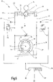
- the hydraulic scheme of the machine tool 10 according to 1 is schematic in 6 shown.
- the hydraulic generator 22 In the upper half of 6 the hydraulic generator 22 is shown, which is driven by the drive motor 14 via the motor shaft 15 and the eccentric 18 driven by it.
- the eccentric 18 moves the linear piston 46 within a Fluid cylinder 54.
- the two pressure chambers 50, 52 of the hydraulic generator 22 are connected to the rotary vane motor 30 via fluid lines 42, 43.
- rotary vane motor 30 has two rotary piston fingers 56 lying opposite one another, which are formed directly on tool spindle 34 .
- the counterpart to the rotary piston fingers 56 on the tool spindle 34 is formed by a correspondingly shaped bushing 32, which is preferably made of bronze.
- a fluid space 57 , 58 or 71 , 72 is formed on both sides of each rotary piston finger 56 between the tool spindle 34 and the bush 32 .
- Opposite fluid chambers 57, 72 and 58, 71 acting in the same direction of rotation are each coupled together with the associated fluid line 42 and 43, respectively.
- both fluid lines 42, 43 can be connected to a pressure relief valve 64 or 63, respectively.
- the pressure relief valves 63, 64 are purely optional. If this is not done, this can be taken into account by adequate dimensioning. In the borderline case, the drive motor 14 slows down and thus prevents a further increase in pressure. By dispensing with the pressure relief valves 63, 64, drifting of the tool spindle 34 out of the central position is counteracted.
- a pressurized fluid reservoir 66, 67 is connected via a common line 70 to both lines 42, 43 via assigned check valves 62 and 61, respectively.
- a suitable quantity of hydraulic fluid is accommodated in a fluid cylinder 66 for this purpose. This is acted upon by the pressure of a suitably dimensioned spring 68 via a piston 67 .
- a specific fluid pressure is thus set in line 70, which can be in the range from 2.9 to 5.2 bar, for example. If the pressure in one of the two lines 42, 43 drops below this value, then hydraulic fluid is pumped out of the fluid cylinder 66.
- the check valves preferably have an opening pressure of 0.2 bar.
- a bypass throttle 60 is also arranged between the two lines 42, 43, which are connected to the pressure chambers 50, 52 of the fluid cylinder 54
- the amplitude of the oscillating movement of the tool spindle 34 can be adjusted continuously, and the tool spindle can be manually adjusted to the central position when the bypass throttle 60 is open.
Landscapes
- Engineering & Computer Science (AREA)
- Mechanical Engineering (AREA)
- Physics & Mathematics (AREA)
- Fluid Mechanics (AREA)
- General Engineering & Computer Science (AREA)
- Life Sciences & Earth Sciences (AREA)
- Forests & Forestry (AREA)
- Mining & Mineral Resources (AREA)
- Architecture (AREA)
- Civil Engineering (AREA)
- Structural Engineering (AREA)
- Hydraulic Motors (AREA)
Claims (12)
- Machine-outil oscillante, avec une broche porte-outil (34) montée de manière à pouvoir tourner autour de son axe longitudinal (35), avec un moteur d'entraînement (14), dans laquelle la machine-outil (10) est conçue pour entraîner en rotation-oscillation la broche porte-outil (34) avec une fréquence d'oscillation de 5000 à 30000 par minute et avec un angle de pivotement de ± 1° à ± 5° d'un point d'inversion à l'autre, dans laquelle la machine-outil est caractérisée en ce que le moteur d'entraînement (14) est couplé à un générateur hydraulique (22) pour générer un flux de fluide oscillant qui entraîne un moteur hydraulique sous la forme d'un moteur à palettes rotatives (30) pour entraîner en oscillation la broche porte-outil (34) autour de son axe longitudinal (35).
- Machine-outil selon la revendication 1, caractérisée en ce que le moteur à palettes rotatives (30) présente des palettes rotatives (38) disposées symétriquement.
- Machine-outil selon la revendication 1 ou 2, caractérisée en ce que les palettes rotatives (38) sont réalisées comme des doigts de piston rotatif sur la broche porte-outil (34).
- Machine-outil selon l'une quelconque des revendications précédentes, caractérisée en ce que la broche porte-outil (34) tourne dans une douille (32) formée en tant que contre-pièce.
- Machine-outil selon les revendications 3 et 4, caractérisée en ce que sont formées, des deux côtés de chaque doigt de piston rotatif (38), avec la douille (32), des chambres de fluide (40, 41) qui sont couplées à des raccords à pulsations de pression opposées (42, 43) du générateur hydraulique (22).
- Machine-outil selon la revendication 4 ou 5, caractérisée en ce que la douille (32) est constituée d'un alliage de bronze et la broche porte-outil (34) est constituée de préférence d'acier.
- Machine-outil selon l'une quelconque des revendications précédentes, caractérisée en ce que le moteur à palettes rotatives (30) présente quatre doigts de piston rotatif (38) qui sont disposés de manière décalée selon un angle respectivement de 90° les uns par rapport aux autres.
- Machine-outil selon l'une quelconque des revendications précédentes, caractérisée en ce que le générateur hydraulique (22) est réalisé comme une pompe volumétrique avec un piston linéaire (46) qui est entraîné par l'intermédiaire d'un excentrique (18) par un arbre moteur (15) du moteur d'entraînement (14).
- Machine-outil selon la revendication 8, caractérisée en ce que sont formées sur les deux extrémités du piston linéaire (46) des chambres de pression (50, 52), dans lesquelles l'énergie de fluide à pulsations opposées est produite.
- Machine-outil selon les revendications 5 et 9, caractérisée en ce que chacune des chambres de pression (50, 52) est couplée par l'intermédiaire d'un distributeur (42, 43) à des alésages (44, 45) associés sur la douille (32) pour alimenter les chambres de fluide (40, 41) des deux côtés des doigts de piston rotatif (38) en fluide à pulsations opposées.
- Machine-outil selon l'une quelconque des revendications précédentes, caractérisée en ce qu'est prévu un réservoir de fluide hydraulique soumis à l'action d'une pression (66, 67) qui est couplé au générateur hydraulique par l'intermédiaire de clapets anti-retour (61, 62) pour compenser des pertes par fuites.
- Machine-outil selon la revendication 11, caractérisée en ce que le réservoir de fluide hydraulique comprend un cylindre (66), dans lequel peut être coulissé un piston (67), qui est précontraint au moyen d'un élément ressort (68) .
Applications Claiming Priority (3)
| Application Number | Priority Date | Filing Date | Title |
|---|---|---|---|
| DE102013112455.0A DE102013112455A1 (de) | 2013-11-13 | 2013-11-13 | Oszillierend antreibbare Werkzeugmaschine |
| DE201410102131 DE102014102131A1 (de) | 2013-11-13 | 2014-02-19 | Oszillierend antreibbare Werkzeugmaschine |
| PCT/EP2014/074366 WO2015071304A1 (fr) | 2013-11-13 | 2014-11-12 | Machine-outil pouvant être entraînée en oscillation |
Publications (2)
| Publication Number | Publication Date |
|---|---|
| EP3077135A1 EP3077135A1 (fr) | 2016-10-12 |
| EP3077135B1 true EP3077135B1 (fr) | 2023-01-11 |
Family
ID=51871040
Family Applications (2)
| Application Number | Title | Priority Date | Filing Date |
|---|---|---|---|
| EP14796086.8A Active EP3068586B1 (fr) | 2013-11-13 | 2014-11-10 | Machine-outil à entraînement oscillant |
| EP14796511.5A Active EP3077135B1 (fr) | 2013-11-13 | 2014-11-12 | Machine-outil pouvant être entraînée en oscillation |
Family Applications Before (1)
| Application Number | Title | Priority Date | Filing Date |
|---|---|---|---|
| EP14796086.8A Active EP3068586B1 (fr) | 2013-11-13 | 2014-11-10 | Machine-outil à entraînement oscillant |
Country Status (4)
| Country | Link |
|---|---|
| US (1) | US10093011B2 (fr) |
| EP (2) | EP3068586B1 (fr) |
| DE (1) | DE102013112455A1 (fr) |
| WO (2) | WO2015071204A1 (fr) |
Families Citing this family (5)
| Publication number | Priority date | Publication date | Assignee | Title |
|---|---|---|---|---|
| DE102013112455A1 (de) * | 2013-11-13 | 2015-05-13 | C. & E. Fein Gmbh | Oszillierend antreibbare Werkzeugmaschine |
| JP6469557B2 (ja) * | 2015-10-05 | 2019-02-13 | 株式会社オグラ | 油圧作動装置 |
| DE102017107485A1 (de) | 2017-04-07 | 2018-10-11 | C. & E. Fein Gmbh | Oszillierend antreibbares Handwerkzeug und Verfahren zum Betreiben eines solchen |
| CN115836900B (zh) * | 2022-12-06 | 2025-10-31 | 上海博进医疗器械有限公司 | 医用摆锯 |
| CN115847243A (zh) * | 2022-12-21 | 2023-03-28 | 成都市鸿侠科技有限责任公司 | 一种基于视觉技术准确性高的飞机发动机薄叶片加工装置 |
Citations (2)
| Publication number | Priority date | Publication date | Assignee | Title |
|---|---|---|---|---|
| EP2283979A2 (fr) * | 2009-08-11 | 2011-02-16 | C. & E. Fein GmbH | Outil manuel doté d'un entraînement par oscillations |
| DE202012101137U1 (de) * | 2012-03-29 | 2012-04-18 | Reinhard Diem | Hydraulische Drehantriebsvorrichtung |
Family Cites Families (34)
| Publication number | Priority date | Publication date | Assignee | Title |
|---|---|---|---|---|
| US1727276A (en) * | 1929-04-22 | 1929-09-03 | Webster L Diehl | Hydraulic rotary drill |
| GB567549A (en) * | 1943-05-25 | 1945-02-20 | Bristol Aeroplane Co Ltd | Improvements in or relating to machines for producing convex surfaces |
| NL267764A (fr) * | 1960-08-03 | |||
| US3552500A (en) * | 1968-08-07 | 1971-01-05 | Ingersoll Rand Co | Hydraulic drill |
| US3695367A (en) * | 1970-06-08 | 1972-10-03 | North American Rockwell | Hydraulic power tool |
| DE2313402A1 (de) * | 1973-03-17 | 1974-09-26 | Bosch Gmbh Robert | Drehschlagwerkzeug |
| CH620853A5 (fr) * | 1977-12-09 | 1980-12-31 | Arnegger Richard E | |
| EP0248986B1 (fr) * | 1986-06-09 | 1992-03-04 | AlliedSignal Inc. | Actionneur hydraulique à clapet oscillant |
| RU2074083C1 (ru) * | 1992-07-15 | 1997-02-27 | Товарищество с ограниченной ответственностью "Научно-производственное предприятие нестандартных изделий машиностроения" | Устройство для суперфиниширования |
| USRE36848E (en) * | 1992-07-17 | 2000-09-05 | Smith International, Inc. | Air percussion drilling assembly |
| US5833444A (en) * | 1994-01-13 | 1998-11-10 | Harris; Gary L. | Fluid driven motors |
| US5577564A (en) * | 1995-02-28 | 1996-11-26 | Dresser Industries, Inc. | Rotary fluid converter |
| NO300231B1 (no) * | 1995-03-31 | 1997-04-28 | Norske Stats Oljeselskap | Trykkforsterker (B) |
| JPH09267251A (ja) * | 1996-04-02 | 1997-10-14 | S P Air Kk | 研磨装置 |
| US5803187A (en) * | 1996-08-23 | 1998-09-08 | Javins; Brooks H. | Rotary-percussion drill apparatus and method |
| US5996523A (en) * | 1998-05-04 | 1999-12-07 | Damir Anton Fox | Hydraulic oscillator |
| FI114436B (fi) * | 2000-07-07 | 2004-10-29 | Plustech Oy | Muunninyksikkö |
| US6520271B1 (en) * | 2000-10-24 | 2003-02-18 | Leo A. Martini | Fluid powered rotary drilling assembly |
| DE10210756A1 (de) * | 2002-03-12 | 2003-10-16 | Sorg Reinhard | Drehkolbenvorrichtung |
| DE10260213A1 (de) | 2002-12-13 | 2004-06-24 | C. & E. Fein Gmbh | Oszillationsantrieb |
| US7703551B2 (en) * | 2005-06-21 | 2010-04-27 | Bow River Tools And Services Ltd. | Fluid driven drilling motor and system |
| US7614227B2 (en) * | 2006-08-04 | 2009-11-10 | Briggs And Stratton Corporation | Rotary control valve for a hydrostatic transmission |
| US8276430B2 (en) * | 2006-09-11 | 2012-10-02 | Cembre S.P.A. | Hydraulic pressing and/or cutting tool and mechanism for converting a rotary motion into a translational oscillating motion for this tool |
| DE102008042378A1 (de) * | 2008-09-26 | 2010-04-01 | Robert Bosch Gmbh | Exzentertriebwerk |
| DE202008013877U1 (de) | 2008-10-20 | 2009-01-08 | Diem, Reinhard | Vorrichtung zum Erzeugen eines oszillierenden Fluidstroms sowie Vorrichtung zum Erzeugen eines oszillierenden Hubes eines Werkzeugs |
| US8240394B2 (en) * | 2008-12-09 | 2012-08-14 | Sp Air Kabushiki Kaisha | Hammer with vibration reduction mechanism |
| CN101890671B (zh) * | 2009-02-17 | 2014-05-28 | C.&E.泛音有限公司 | 用于振动驱动装置的磨削或磨光的工具 |
| DE102009055843A1 (de) * | 2009-11-26 | 2011-06-01 | Robert Bosch Gmbh | Antrieb, insbesondere für Rundachsen |
| CA2837938C (fr) * | 2011-03-29 | 2019-04-30 | Coil Tubing Technology, Inc. | Oscillateur de fond de trou |
| CN103370169A (zh) * | 2011-12-30 | 2013-10-23 | 坎贝尔·豪斯费尔德/斯科特·费策尔公司 | 手持式工具及其部件 |
| JP5620941B2 (ja) * | 2012-04-26 | 2014-11-05 | Thk株式会社 | 垂直軸型流体発電装置の回転軸装置及び垂直軸型流体発電装置 |
| US9486908B2 (en) * | 2013-06-18 | 2016-11-08 | Ingersoll-Rand Company | Rotary impact tool |
| DE102013112455A1 (de) * | 2013-11-13 | 2015-05-13 | C. & E. Fein Gmbh | Oszillierend antreibbare Werkzeugmaschine |
| US10301879B2 (en) * | 2014-01-21 | 2019-05-28 | Halliburton Energy Services, Inc. | Variable valve axial oscillation tool |
-
2013
- 2013-11-13 DE DE102013112455.0A patent/DE102013112455A1/de not_active Withdrawn
-
2014
- 2014-11-10 EP EP14796086.8A patent/EP3068586B1/fr active Active
- 2014-11-10 WO PCT/EP2014/074126 patent/WO2015071204A1/fr not_active Ceased
- 2014-11-12 EP EP14796511.5A patent/EP3077135B1/fr active Active
- 2014-11-12 WO PCT/EP2014/074366 patent/WO2015071304A1/fr not_active Ceased
-
2016
- 2016-05-12 US US15/153,080 patent/US10093011B2/en active Active
Patent Citations (2)
| Publication number | Priority date | Publication date | Assignee | Title |
|---|---|---|---|---|
| EP2283979A2 (fr) * | 2009-08-11 | 2011-02-16 | C. & E. Fein GmbH | Outil manuel doté d'un entraînement par oscillations |
| DE202012101137U1 (de) * | 2012-03-29 | 2012-04-18 | Reinhard Diem | Hydraulische Drehantriebsvorrichtung |
Also Published As
| Publication number | Publication date |
|---|---|
| US20160256993A1 (en) | 2016-09-08 |
| DE102013112455A1 (de) | 2015-05-13 |
| US10093011B2 (en) | 2018-10-09 |
| EP3068586A1 (fr) | 2016-09-21 |
| WO2015071304A1 (fr) | 2015-05-21 |
| EP3068586B1 (fr) | 2022-10-26 |
| EP3077135A1 (fr) | 2016-10-12 |
| WO2015071204A1 (fr) | 2015-05-21 |
Similar Documents
| Publication | Publication Date | Title |
|---|---|---|
| EP1184567B1 (fr) | Boîte d'engrenage pour éoliennes | |
| EP3077135B1 (fr) | Machine-outil pouvant être entraînée en oscillation | |
| DE102013200402B4 (de) | Nockenwellenversteller | |
| WO2013167286A2 (fr) | Turbine kaplan à corps d'aube réglables | |
| DE2630973A1 (de) | Hydrostatisches getriebe zum umformen einer rotations- in eine hin- und hergehende schwenkbewegung | |
| DE102015211477B4 (de) | Hydrostatischer Kupplungsaktor | |
| DE102014102131A1 (de) | Oszillierend antreibbare Werkzeugmaschine | |
| EP1111234B1 (fr) | Pompe à carburant | |
| DE102008019072B3 (de) | Kurvengetriebe, insbesondere für eine Kolbenpumpe für die Hochleistungsflüssigkeitschromatographie | |
| AT3212U1 (de) | Radialkolbenpumpe | |
| DE1001074C2 (de) | Stufenlos regelbares Schaltwerksgetriebe | |
| DE3734926C2 (fr) | ||
| DE1625152B2 (de) | Lagerung fuer die axialkolbenpumpe eines hydrostatischen getriebes | |
| AT516340B1 (de) | Schmiedevorrichtung mit in Hubrichtung geführten, Schmiedewerkzeuge aufnehmenden Stempeln | |
| DE151603C (fr) | ||
| DE171513C (fr) | ||
| EP2857689B1 (fr) | Machine à pistons à train épicycloïdal dotée d'un système de levage, disposée sur un axe | |
| CH177014A (de) | Flüssigkeits-Wechselgetriebe. | |
| DE102012222700A1 (de) | Verstelleinrichtung und Axialkolbenmaschine | |
| DE4402992A1 (de) | Vorrichtung zur relativen Drehwinkelverstellung einer Welle mit einer Kolbenpumpe | |
| DE102004024728B3 (de) | Schalteinrichtung für mehrstufige Ölpumpen | |
| DE1625152C3 (de) | Lagerung für die Axialkolbenpumpe eines hydrostatischen Getriebes | |
| DE202011109897U1 (de) | Mehrkolben-Reihenpumpe | |
| DE8007819U1 (de) | Antriebsmechanismus fuer kolbenmaschinen | |
| DEE0010911MA (fr) |
Legal Events
| Date | Code | Title | Description |
|---|---|---|---|
| PUAI | Public reference made under article 153(3) epc to a published international application that has entered the european phase |
Free format text: ORIGINAL CODE: 0009012 |
|
| 17P | Request for examination filed |
Effective date: 20160610 |
|
| AK | Designated contracting states |
Kind code of ref document: A1 Designated state(s): AL AT BE BG CH CY CZ DE DK EE ES FI FR GB GR HR HU IE IS IT LI LT LU LV MC MK MT NL NO PL PT RO RS SE SI SK SM TR |
|
| AX | Request for extension of the european patent |
Extension state: BA ME |
|
| DAX | Request for extension of the european patent (deleted) | ||
| STAA | Information on the status of an ep patent application or granted ep patent |
Free format text: STATUS: EXAMINATION IS IN PROGRESS |
|
| 17Q | First examination report despatched |
Effective date: 20191122 |
|
| GRAP | Despatch of communication of intention to grant a patent |
Free format text: ORIGINAL CODE: EPIDOSNIGR1 |
|
| STAA | Information on the status of an ep patent application or granted ep patent |
Free format text: STATUS: GRANT OF PATENT IS INTENDED |
|
| INTG | Intention to grant announced |
Effective date: 20220908 |
|
| GRAS | Grant fee paid |
Free format text: ORIGINAL CODE: EPIDOSNIGR3 |
|
| GRAA | (expected) grant |
Free format text: ORIGINAL CODE: 0009210 |
|
| STAA | Information on the status of an ep patent application or granted ep patent |
Free format text: STATUS: THE PATENT HAS BEEN GRANTED |
|
| AK | Designated contracting states |
Kind code of ref document: B1 Designated state(s): AL AT BE BG CH CY CZ DE DK EE ES FI FR GB GR HR HU IE IS IT LI LT LU LV MC MK MT NL NO PL PT RO RS SE SI SK SM TR |
|
| REG | Reference to a national code |
Ref country code: GB Ref legal event code: FG4D Free format text: NOT ENGLISH |
|
| REG | Reference to a national code |
Ref country code: CH Ref legal event code: EP |
|
| REG | Reference to a national code |
Ref country code: DE Ref legal event code: R096 Ref document number: 502014016479 Country of ref document: DE |
|
| REG | Reference to a national code |
Ref country code: IE Ref legal event code: FG4D Free format text: LANGUAGE OF EP DOCUMENT: GERMAN |
|
| REG | Reference to a national code |
Ref country code: AT Ref legal event code: REF Ref document number: 1543089 Country of ref document: AT Kind code of ref document: T Effective date: 20230215 |
|
| REG | Reference to a national code |
Ref country code: LT Ref legal event code: MG9D |
|
| REG | Reference to a national code |
Ref country code: NL Ref legal event code: MP Effective date: 20230111 |
|
| P01 | Opt-out of the competence of the unified patent court (upc) registered |
Effective date: 20230511 |
|
| PG25 | Lapsed in a contracting state [announced via postgrant information from national office to epo] |
Ref country code: NL Free format text: LAPSE BECAUSE OF FAILURE TO SUBMIT A TRANSLATION OF THE DESCRIPTION OR TO PAY THE FEE WITHIN THE PRESCRIBED TIME-LIMIT Effective date: 20230111 |
|
| PG25 | Lapsed in a contracting state [announced via postgrant information from national office to epo] |
Ref country code: RS Free format text: LAPSE BECAUSE OF FAILURE TO SUBMIT A TRANSLATION OF THE DESCRIPTION OR TO PAY THE FEE WITHIN THE PRESCRIBED TIME-LIMIT Effective date: 20230111 Ref country code: PT Free format text: LAPSE BECAUSE OF FAILURE TO SUBMIT A TRANSLATION OF THE DESCRIPTION OR TO PAY THE FEE WITHIN THE PRESCRIBED TIME-LIMIT Effective date: 20230511 Ref country code: NO Free format text: LAPSE BECAUSE OF FAILURE TO SUBMIT A TRANSLATION OF THE DESCRIPTION OR TO PAY THE FEE WITHIN THE PRESCRIBED TIME-LIMIT Effective date: 20230411 Ref country code: LV Free format text: LAPSE BECAUSE OF FAILURE TO SUBMIT A TRANSLATION OF THE DESCRIPTION OR TO PAY THE FEE WITHIN THE PRESCRIBED TIME-LIMIT Effective date: 20230111 Ref country code: LT Free format text: LAPSE BECAUSE OF FAILURE TO SUBMIT A TRANSLATION OF THE DESCRIPTION OR TO PAY THE FEE WITHIN THE PRESCRIBED TIME-LIMIT Effective date: 20230111 Ref country code: HR Free format text: LAPSE BECAUSE OF FAILURE TO SUBMIT A TRANSLATION OF THE DESCRIPTION OR TO PAY THE FEE WITHIN THE PRESCRIBED TIME-LIMIT Effective date: 20230111 Ref country code: ES Free format text: LAPSE BECAUSE OF FAILURE TO SUBMIT A TRANSLATION OF THE DESCRIPTION OR TO PAY THE FEE WITHIN THE PRESCRIBED TIME-LIMIT Effective date: 20230111 |
|
| PG25 | Lapsed in a contracting state [announced via postgrant information from national office to epo] |
Ref country code: SE Free format text: LAPSE BECAUSE OF FAILURE TO SUBMIT A TRANSLATION OF THE DESCRIPTION OR TO PAY THE FEE WITHIN THE PRESCRIBED TIME-LIMIT Effective date: 20230111 Ref country code: PL Free format text: LAPSE BECAUSE OF FAILURE TO SUBMIT A TRANSLATION OF THE DESCRIPTION OR TO PAY THE FEE WITHIN THE PRESCRIBED TIME-LIMIT Effective date: 20230111 Ref country code: IS Free format text: LAPSE BECAUSE OF FAILURE TO SUBMIT A TRANSLATION OF THE DESCRIPTION OR TO PAY THE FEE WITHIN THE PRESCRIBED TIME-LIMIT Effective date: 20230511 Ref country code: GR Free format text: LAPSE BECAUSE OF FAILURE TO SUBMIT A TRANSLATION OF THE DESCRIPTION OR TO PAY THE FEE WITHIN THE PRESCRIBED TIME-LIMIT Effective date: 20230412 Ref country code: FI Free format text: LAPSE BECAUSE OF FAILURE TO SUBMIT A TRANSLATION OF THE DESCRIPTION OR TO PAY THE FEE WITHIN THE PRESCRIBED TIME-LIMIT Effective date: 20230111 |
|
| REG | Reference to a national code |
Ref country code: DE Ref legal event code: R097 Ref document number: 502014016479 Country of ref document: DE |
|
| PG25 | Lapsed in a contracting state [announced via postgrant information from national office to epo] |
Ref country code: SM Free format text: LAPSE BECAUSE OF FAILURE TO SUBMIT A TRANSLATION OF THE DESCRIPTION OR TO PAY THE FEE WITHIN THE PRESCRIBED TIME-LIMIT Effective date: 20230111 Ref country code: RO Free format text: LAPSE BECAUSE OF FAILURE TO SUBMIT A TRANSLATION OF THE DESCRIPTION OR TO PAY THE FEE WITHIN THE PRESCRIBED TIME-LIMIT Effective date: 20230111 Ref country code: EE Free format text: LAPSE BECAUSE OF FAILURE TO SUBMIT A TRANSLATION OF THE DESCRIPTION OR TO PAY THE FEE WITHIN THE PRESCRIBED TIME-LIMIT Effective date: 20230111 Ref country code: DK Free format text: LAPSE BECAUSE OF FAILURE TO SUBMIT A TRANSLATION OF THE DESCRIPTION OR TO PAY THE FEE WITHIN THE PRESCRIBED TIME-LIMIT Effective date: 20230111 Ref country code: CZ Free format text: LAPSE BECAUSE OF FAILURE TO SUBMIT A TRANSLATION OF THE DESCRIPTION OR TO PAY THE FEE WITHIN THE PRESCRIBED TIME-LIMIT Effective date: 20230111 |
|
| PLBE | No opposition filed within time limit |
Free format text: ORIGINAL CODE: 0009261 |
|
| STAA | Information on the status of an ep patent application or granted ep patent |
Free format text: STATUS: NO OPPOSITION FILED WITHIN TIME LIMIT |
|
| PG25 | Lapsed in a contracting state [announced via postgrant information from national office to epo] |
Ref country code: SK Free format text: LAPSE BECAUSE OF FAILURE TO SUBMIT A TRANSLATION OF THE DESCRIPTION OR TO PAY THE FEE WITHIN THE PRESCRIBED TIME-LIMIT Effective date: 20230111 |
|
| 26N | No opposition filed |
Effective date: 20231012 |
|
| PG25 | Lapsed in a contracting state [announced via postgrant information from national office to epo] |
Ref country code: SI Free format text: LAPSE BECAUSE OF FAILURE TO SUBMIT A TRANSLATION OF THE DESCRIPTION OR TO PAY THE FEE WITHIN THE PRESCRIBED TIME-LIMIT Effective date: 20230111 |
|
| PG25 | Lapsed in a contracting state [announced via postgrant information from national office to epo] |
Ref country code: IT Free format text: LAPSE BECAUSE OF FAILURE TO SUBMIT A TRANSLATION OF THE DESCRIPTION OR TO PAY THE FEE WITHIN THE PRESCRIBED TIME-LIMIT Effective date: 20230111 |
|
| REG | Reference to a national code |
Ref country code: CH Ref legal event code: PL |
|
| PG25 | Lapsed in a contracting state [announced via postgrant information from national office to epo] |
Ref country code: MC Free format text: LAPSE BECAUSE OF FAILURE TO SUBMIT A TRANSLATION OF THE DESCRIPTION OR TO PAY THE FEE WITHIN THE PRESCRIBED TIME-LIMIT Effective date: 20230111 |
|
| PG25 | Lapsed in a contracting state [announced via postgrant information from national office to epo] |
Ref country code: LU Free format text: LAPSE BECAUSE OF NON-PAYMENT OF DUE FEES Effective date: 20231112 |
|
| PG25 | Lapsed in a contracting state [announced via postgrant information from national office to epo] |
Ref country code: CH Free format text: LAPSE BECAUSE OF NON-PAYMENT OF DUE FEES Effective date: 20231130 |
|
| GBPC | Gb: european patent ceased through non-payment of renewal fee |
Effective date: 20231112 |
|
| PG25 | Lapsed in a contracting state [announced via postgrant information from national office to epo] |
Ref country code: MC Free format text: LAPSE BECAUSE OF FAILURE TO SUBMIT A TRANSLATION OF THE DESCRIPTION OR TO PAY THE FEE WITHIN THE PRESCRIBED TIME-LIMIT Effective date: 20230111 Ref country code: LU Free format text: LAPSE BECAUSE OF NON-PAYMENT OF DUE FEES Effective date: 20231112 Ref country code: CH Free format text: LAPSE BECAUSE OF NON-PAYMENT OF DUE FEES Effective date: 20231130 |
|
| REG | Reference to a national code |
Ref country code: BE Ref legal event code: MM Effective date: 20231130 |
|
| REG | Reference to a national code |
Ref country code: IE Ref legal event code: MM4A |
|
| PG25 | Lapsed in a contracting state [announced via postgrant information from national office to epo] |
Ref country code: IE Free format text: LAPSE BECAUSE OF NON-PAYMENT OF DUE FEES Effective date: 20231112 |
|
| PG25 | Lapsed in a contracting state [announced via postgrant information from national office to epo] |
Ref country code: GB Free format text: LAPSE BECAUSE OF NON-PAYMENT OF DUE FEES Effective date: 20231112 |
|
| PG25 | Lapsed in a contracting state [announced via postgrant information from national office to epo] |
Ref country code: BE Free format text: LAPSE BECAUSE OF NON-PAYMENT OF DUE FEES Effective date: 20231130 |
|
| PG25 | Lapsed in a contracting state [announced via postgrant information from national office to epo] |
Ref country code: FR Free format text: LAPSE BECAUSE OF NON-PAYMENT OF DUE FEES Effective date: 20231130 |
|
| PG25 | Lapsed in a contracting state [announced via postgrant information from national office to epo] |
Ref country code: IE Free format text: LAPSE BECAUSE OF NON-PAYMENT OF DUE FEES Effective date: 20231112 Ref country code: GB Free format text: LAPSE BECAUSE OF NON-PAYMENT OF DUE FEES Effective date: 20231112 Ref country code: FR Free format text: LAPSE BECAUSE OF NON-PAYMENT OF DUE FEES Effective date: 20231130 Ref country code: BE Free format text: LAPSE BECAUSE OF NON-PAYMENT OF DUE FEES Effective date: 20231130 |
|
| PG25 | Lapsed in a contracting state [announced via postgrant information from national office to epo] |
Ref country code: BG Free format text: LAPSE BECAUSE OF FAILURE TO SUBMIT A TRANSLATION OF THE DESCRIPTION OR TO PAY THE FEE WITHIN THE PRESCRIBED TIME-LIMIT Effective date: 20230111 |
|
| PG25 | Lapsed in a contracting state [announced via postgrant information from national office to epo] |
Ref country code: BG Free format text: LAPSE BECAUSE OF FAILURE TO SUBMIT A TRANSLATION OF THE DESCRIPTION OR TO PAY THE FEE WITHIN THE PRESCRIBED TIME-LIMIT Effective date: 20230111 |
|
| REG | Reference to a national code |
Ref country code: AT Ref legal event code: MM01 Ref document number: 1543089 Country of ref document: AT Kind code of ref document: T Effective date: 20231112 |
|
| PG25 | Lapsed in a contracting state [announced via postgrant information from national office to epo] |
Ref country code: AT Free format text: LAPSE BECAUSE OF NON-PAYMENT OF DUE FEES Effective date: 20231112 |
|
| PG25 | Lapsed in a contracting state [announced via postgrant information from national office to epo] |
Ref country code: AT Free format text: LAPSE BECAUSE OF NON-PAYMENT OF DUE FEES Effective date: 20231112 |
|
| PG25 | Lapsed in a contracting state [announced via postgrant information from national office to epo] |
Ref country code: CY Free format text: LAPSE BECAUSE OF FAILURE TO SUBMIT A TRANSLATION OF THE DESCRIPTION OR TO PAY THE FEE WITHIN THE PRESCRIBED TIME-LIMIT; INVALID AB INITIO Effective date: 20141112 |
|
| PG25 | Lapsed in a contracting state [announced via postgrant information from national office to epo] |
Ref country code: HU Free format text: LAPSE BECAUSE OF FAILURE TO SUBMIT A TRANSLATION OF THE DESCRIPTION OR TO PAY THE FEE WITHIN THE PRESCRIBED TIME-LIMIT; INVALID AB INITIO Effective date: 20141112 |
|
| PG25 | Lapsed in a contracting state [announced via postgrant information from national office to epo] |
Ref country code: TR Free format text: LAPSE BECAUSE OF FAILURE TO SUBMIT A TRANSLATION OF THE DESCRIPTION OR TO PAY THE FEE WITHIN THE PRESCRIBED TIME-LIMIT Effective date: 20230111 |
|
| PGFP | Annual fee paid to national office [announced via postgrant information from national office to epo] |
Ref country code: DE Payment date: 20251118 Year of fee payment: 12 |