EP3078443B1 - Procédé et système de commande numérique améliorée du découpage au plasma de pièces à partir d'une pièce à usiner - Google Patents
Procédé et système de commande numérique améliorée du découpage au plasma de pièces à partir d'une pièce à usiner Download PDFInfo
- Publication number
- EP3078443B1 EP3078443B1 EP16160983.9A EP16160983A EP3078443B1 EP 3078443 B1 EP3078443 B1 EP 3078443B1 EP 16160983 A EP16160983 A EP 16160983A EP 3078443 B1 EP3078443 B1 EP 3078443B1
- Authority
- EP
- European Patent Office
- Prior art keywords
- cutting
- cut
- plasma
- parts
- torch
- Prior art date
- Legal status (The legal status is an assumption and is not a legal conclusion. Google has not performed a legal analysis and makes no representation as to the accuracy of the status listed.)
- Active
Links
Images







Classifications
-
- B—PERFORMING OPERATIONS; TRANSPORTING
- B23—MACHINE TOOLS; METAL-WORKING NOT OTHERWISE PROVIDED FOR
- B23K—SOLDERING OR UNSOLDERING; WELDING; CLADDING OR PLATING BY SOLDERING OR WELDING; CUTTING BY APPLYING HEAT LOCALLY, e.g. FLAME CUTTING; WORKING BY LASER BEAM
- B23K10/00—Welding or cutting by means of a plasma
- B23K10/006—Control circuits therefor
-
- B—PERFORMING OPERATIONS; TRANSPORTING
- B23—MACHINE TOOLS; METAL-WORKING NOT OTHERWISE PROVIDED FOR
- B23K—SOLDERING OR UNSOLDERING; WELDING; CLADDING OR PLATING BY SOLDERING OR WELDING; CUTTING BY APPLYING HEAT LOCALLY, e.g. FLAME CUTTING; WORKING BY LASER BEAM
- B23K10/00—Welding or cutting by means of a plasma
-
- B—PERFORMING OPERATIONS; TRANSPORTING
- B23—MACHINE TOOLS; METAL-WORKING NOT OTHERWISE PROVIDED FOR
- B23K—SOLDERING OR UNSOLDERING; WELDING; CLADDING OR PLATING BY SOLDERING OR WELDING; CUTTING BY APPLYING HEAT LOCALLY, e.g. FLAME CUTTING; WORKING BY LASER BEAM
- B23K31/00—Processes relevant to this subclass, specially adapted for particular articles or purposes, but not covered by any single one of main groups B23K1/00 - B23K28/00
- B23K31/10—Processes relevant to this subclass, specially adapted for particular articles or purposes, but not covered by any single one of main groups B23K1/00 - B23K28/00 relating to cutting or desurfacing
-
- B—PERFORMING OPERATIONS; TRANSPORTING
- B23—MACHINE TOOLS; METAL-WORKING NOT OTHERWISE PROVIDED FOR
- B23K—SOLDERING OR UNSOLDERING; WELDING; CLADDING OR PLATING BY SOLDERING OR WELDING; CUTTING BY APPLYING HEAT LOCALLY, e.g. FLAME CUTTING; WORKING BY LASER BEAM
- B23K37/00—Auxiliary devices or processes, not specially adapted for a procedure covered by only one of the other main groups of this subclass
- B23K37/02—Carriages for supporting the welding or cutting element
- B23K37/0258—Electric supply or control circuits therefor
-
- G—PHYSICS
- G05—CONTROLLING; REGULATING
- G05B—CONTROL OR REGULATING SYSTEMS IN GENERAL; FUNCTIONAL ELEMENTS OF SUCH SYSTEMS; MONITORING OR TESTING ARRANGEMENTS FOR SUCH SYSTEMS OR ELEMENTS
- G05B19/00—Program-control systems
- G05B19/02—Program-control systems electric
- G05B19/18—Numerical control [NC], i.e. automatically operating machines, in particular machine tools, e.g. in a manufacturing environment, so as to execute positioning, movement or co-ordinated operations by means of program data in numerical form
- G05B19/4155—Numerical control [NC], i.e. automatically operating machines, in particular machine tools, e.g. in a manufacturing environment, so as to execute positioning, movement or co-ordinated operations by means of program data in numerical form characterised by program execution, i.e. part program or machine function execution, e.g. selection of a program
-
- G—PHYSICS
- G05—CONTROLLING; REGULATING
- G05B—CONTROL OR REGULATING SYSTEMS IN GENERAL; FUNCTIONAL ELEMENTS OF SUCH SYSTEMS; MONITORING OR TESTING ARRANGEMENTS FOR SUCH SYSTEMS OR ELEMENTS
- G05B2219/00—Program-control systems
- G05B2219/30—Nc systems
- G05B2219/45—Nc applications
- G05B2219/45044—Cutting
Definitions
- the application relates to the field of part cutting from sheets or plates and more specifically to methods for improving part cutting by employing varying degrees of overlap of cut lines and arcs between adjacent parts and efficiently eliminating or disposing of remnants thereof.
- Oxy acetylene plate cutting was the universal method used in the first half of the 20 th century.
- Electronic optically guided sheet and plate steel cutting machines appeared in the 1960s, machines which copied a drawn template by using a 'magic eye.'
- Plasma cutting was a much faster method but gave a poor cut quality, although adequate if the edge was going to be ground for welding.
- a plasma torch cuts up to 10 times faster than an oxy acetylene torch.
- An inert plasma gas could even be used for cutting highly combustible materials such as aluminum.
- Another advantage of plasma cutting is that the high speed combined with the ejection of hot molten material rather than combustion of the material reduced heat input into the plate and this in turn reduced potentially large thermally induced part movement during cutting.
- Such Numeric Control machines are used to cut flat plates or sheets into single parts or a collection of such parts on a plate, which is known as a nest.
- the parts within the nest are positioned by an NC programmer or by automatic nesting software to waste less metal.
- US2014/0060271 discloses a method and system for cutting parts using a beam cutting technology. A set of rules govern the clustering of parts such that they are positioned only a thickness of one cut from each other.
- US2014/0288691 upon which the preamble of claim 1 is based, discloses a machinery and method for cutting a workpiece using a cutting tool. The cutting pattern is optimized to reduce the amount of material waste remaining after the cutting process.
- An embodiment of the invention comprises, a method for numerical control (NC) plasma cutting of parts from a workpiece, comprising: generating, within a computer, a nest that optimally positions the parts to minimize waste of the workpiece; and generating, based upon the nest, an NC program to control an NC plasma cutting machine to cut the parts from the workpiece using one or both of edge starts and gap starts; wherein the NC program is capable of controlling a plasma cutting torch of the NC plasma cutting machine to cut the parts from the workpiece, wherein the parts are cut from the workpiece using a plasma cutting torch of the NC plasma cutting machine controlled by the NC program, characterized in that the ignition of the plasma arc of the plasma cutting torch takes place during lateral movement of the plasma cutting torch.
- NC numerical control
- a system enhances numerical control (NC) plasma cutting of parts from a workpiece.
- the system includes a processor and a memory communicatively coupled with the processor and storing machine readable instructions.
- the machine readable instructions when executed by the processor, are capable of: (a) starting an arc of a plasma cutting torch while the cutting torch is positioned adjacent an edge of the workpiece and proximate a contour of one of the parts, and (b) immediately moving, when the plasma arc is established, the plasma cutting torch along the edge prior to follow the contour to cut the part from the workpiece.
- the machine readable instructions when executed by the processor, are capable of: (c) positioning the plasma cutting torch at a previously cut path of the workpiece, and (d) starting an arc of the plasma cutting torch while moving the plasma cutting torch along the previously cut path prior to following a contour of one of the parts.
- a system has enhanced numerical control (NC) plasma cutting of parts from a workpiece.
- the system includes a processor and a memory communicatively coupled with the processor and storing machine readable instructions that when executed by the processor are capable of: interpreting an edge start M code of an NC program to (a) start a plasma arc of a cutting torch of an NC cutting machine when the cutting torch is positioned off of and adjacent to an edge of a workpiece, and (b) immediately start lateral movement of the cutting torch when the plasma arc is established; interpreting a gap start M code of the NC program to (c) start the plasma arc of the cutting torch when the cutting torch is positioned over a previously cut path on the workpiece, and (d) immediately start lateral movement of the cutting torch when the plasma arc is established; and interpreting a moving off M code of the NC program to extinguish the plasma arc of the cutting torch without stopping lateral movement of the cutting torch until the plasma arc is extinguished.
- an edge start M code of an NC program to (a)
- a numerical control (NC) plasma cutting machine has an NC controller that includes a processor and a memory storing machine readable instructions that when executed by the processor interpret instructions of an NC program to control a plasma cutting torch of the NC plasma cutting machine to cut out parts from a workpiece.
- the NC controller interprets Geometric moves (G codes) that control movement of the plasma cutting torch and Miscellaneous functions (M codes) that control activation and deactivation of the plasma cutting torch.
- An improvement to the NC controller includes machine readable instructions stored within the memory that when executed by the processor are capable of interpreting an edge start M code to start a plasma arc of the cutting torch while the cutting torch is (a) positioned off and adjacent to an edge of the workpiece and (b) to immediately, once the plasma arc is established, start lateral movement of the cutting torch.
- Path usually refers more specifically to the contour followed by a cutting machine, where it is called a 'tool path' in the general NC parlance.
- a part consists of a single outside profile and perhaps multiple holes in the part which are described as internal profiles cut from a block, sheet, or plate of material, referred to as a workpiece. The following discussion is concerned only with the external or outside profile that contains each part within the nest of parts. Unless a hole is big enough to accommodate smaller parts, it plays no part in the nesting logic.
- kerf' is a word for the width of the cut for a saw blade cutting wood. In all cutting, this is a critical dimension if the cut parts are to be the right size. The term was adopted by the NC industry to describe the amount by which a cut has to be offset to leave the part dimensions correct. This offset also, known as the kerf, is in practice half the cut width. To distinguish these two, the term kerf radius is used in the following description when referring to half the cut width. When cutting shapes, the shape cut from the workpiece is equal to the original shape size plus the width of the cut. This may be quite significant with plasma cutting, where the cut with is as much as 10mm for thick material.
- the cut width or kerf is thus critical to cutting and computations to generate NC programs that cut parts accurately.
- the torch center When cutting a shape, the torch center must be programmed to stay precisely a 'kerf radius' distance from the desired shape so that the part cut is the right size.
- This offsetting of the desired shape to the center of the torch is known as 'kerf compensation' and is one of the more demanding functions of an NC control to convert the programmed shape into the required shape, particularly when allowing for a variable cut width.
- the kerf compensation may be added directly to the NC program before it is sent to the NC cutting machine. In either event, for a dimensionally correct part, the final compensated cutter center path must be precisely one kerf radius outside the outside contour of the part and one kerf radius inside the internal contour (or holes) of the part.
- the plasma kerf is between 4-10 mm for plasma currents in the range of 50 to 1000 amps, corresponding to a range of cutting thicknesses from around 3 mm to 160 mm.
- a cut to each part is separately made by creating a starting hole or "pierce" adjacent to the part and then proceeding to cut or separate the part from the surrounding material.
- pierce there is significant cost associated with creating the pierce as it requires large amounts of energy and time to pierce the material.
- piercing is extremely destructive and must be started a considerable distance from the part to avoid damaging the part, both in the resultant shape of the part and the metallurgy of the part that may be affected by heat during the pierce.
- any material is first pierced to create a hole for an edge cutting tool to work. Rarely is the edge cutting tool suitable for piercing the same material, and therefore a separate process is often used.
- scissors may be used to cut cloth, but making a hole with the scissors is difficult.
- multiple pierces are made. Each pierce is time consuming, wasteful of material, and is damaging. Minimization, and even elimination, of the need to pierce is a real objective because of the savings in time and plasma components. Total elimination of all pierces is impossible in many cases where parts have internal contours or holes but as described herein, the use of created 'opportunities' reduces the number of external pierces and their size such that damage may be reduced and in some cases totally eliminated.
- edge start refers to a cut that starts directly from the edge of a plate. Logically, a pierce creates a hole and then allows edge cutting from that hole. By using an edge start on an existing edge of the workpiece, the need to penetrate the material is removed. Therefore, the edge start is considered a different starting technique.
- edge start there is no such separate edge start operation and all plasma starts presume piercing.
- the edge of the material metal
- the edge of the material must be heated to burning or melting temperature, which requires time.
- Common Line cutting does not reduce the number of pierces required, but does reduce total cutting time, which was the original attraction in the days of slow oxy cutting where a plate could take twelve hours to cut. To complete a profile, often a pierce on the part contour is required, damaging the part. Thus, there are gains and losses.
- Common Line cutting is widely used only in countries like China, where the saving in costly material is more important than the saving in time and labor required to repair parts, by grinding after cutting for example.
- the material to wages cost ratio is for example ten times higher in Asia than in the US and Europe.
- the torch was set up for either clockwise cutting or counterclockwise where the cutting torch is kept on the left or right of the cut surface at all times.
- Cutting on to the left of the part is known as Left Kerf and on the right is known as Right kerf. It was believed that using the wrong kerf direction would result in increased cut width and therefore produce the wrong part size, and often would result in a dramatic slope or bevel to the part edge.
- the cutting torch must be over uncut metal at all times. An attempt to cross a gap will result in the torch going out by losing the arc, in turn causing great disruption as the operator has to restart the program, find the fault point and then attempt a restart the cutting. The part being cut when it extinguished would be damaged and would need to be cut again on yet another nest of parts.
- the torch mist be at least 50%-75% over metal and preferably entirely over metal.
- the plasma arc cannot start in an existing cut between two parts.
- the plasma arc cannot start next to metal unless the torch is substantially or completely over the metal. An established plasma arc would extinguish.
- the plasma arc cannot start between two edges of an existing cut.
- the cutting torch must exit the part edge on closing a cut contour to prevent substantial damage resulting from increased cut width.
- the cutting torch cannot leave a cut path and return along the same cut path without either the torch extinguishing or substantial damage to the part along the original path in terms of cut quality, cut width or chamfer.
- start position was critical to minimize thermal movement from the mechanical advantage of small strips which would push the parts around during cutting, making the cut shape wrong and unacceptable.
- a pierce on a part edge cannot be done without substantial damage to the part.
- the cut width does not increase.
- the cutting torch can travel endlessly around an external contour or an internal hole, even if the metal only remains on one side of the cut, such as when a slug falls out from a cut hole.
- the plasma arc can start in a gap between two parts and proceed to cutting instantly. In fact it is imperative that cutting starts immediately to prevent arc damage to two parts. (See later proposed changes to M codes in NC controls)
- a plasma arc can start adjacent to metal
- a plasma arc can start between two previously cut edges, allowing a previous cut to be continued without damaging either part.
- the cutting torch does not need to exit the cut path at all.
- the arc can continue indefinitely within a previously cut path. More critically, it is important to avoid the typical stationary point of the torch where the arc turns off (see changes to M codes in NC controls)
- the torch may return repeatedly to an existing cut, recut an existing path and may continue without the torch extinguishing and without significant damage to either part. Cut width and chamfer do not increase and in fact chamfer often decreases by removing previously melted metal from the cut.
- a skeleton does not adequately restrain parts in plasma cutting. In fact it is the thin parts of the skeleton that can cause movement by creating large forces where only one side of a thin strip is heated to high temperature.
- the strip deviation unbounded at one end can be shown to be L 2 /W where L is the length of the strip and W is the thickness.
- L is the length of the strip
- W is the thickness.
- the start point is still important in minimizing movement.
- the additional tool possible from 2.2 is that the cutting torch may cut in both directions. Further as a consequence of 2.3 to 2.10, it is possible to cut a part in multiple sections, balancing clockwise (CW) and counter clockwise (CCW) cutting directions and restarting precisely so that there is no damage (See later proposed changes to M codes in NC controls #1)
- Cutting of a profile may be stopped and started multiple times. The biggest use of this is to counter thermal movement.
- kerf compensation is performed by external software and not exclusively by NC controls.
- many older NC controls do not permit changes of kerf (e.g., from left to right) during execution of a NC Program. Further these older NC controls use an unacceptable type of mathematical construction, even on simple corners, producing a pointy corner that may cut into adjacent parts.
- nesting software running on a computer having a processor and a memory, may precisely place the parts a cut width or kerf distance apart.
- parts with common cut lines are placed with a separation equal to the cut width.
- Prior art systems then spaced other parts more conventionally with a part to part gap that is at least two times the cut width plus a further arbitrary separation.
- all parts need be separated only by the cut width, such that the cutting overlaps at points where the parts are within a kerf width of each other.
- cutting of the nest should commence from the same left or bottom edges. If this is not possible, a traditional pierce and entry may be used. Thereafter, the goal is to avoid piercing again by making use of the cut path of any previously cut part to start cutting the outer boundary of another part.
- Internal holes in parts may be cut conventionally except that only one pierce is required to form the hole, even when additional parts are to be cut from the material removed from that hole.
- Cutting may be restarted in an existing cut without significant damage. This may be done to continue a cut after stopping or to start cutting of an adjoining part with an overlapping cut path.
- the plasma arc may be started with the torch positioned slightly off the plate itself, such as when the torch is placed to the side of the plate and immediately next to the plate edge. If the type of plasma torch being used cannot start at the edge of the plate, the plate edge itself cannot be incorporated in the cut part shapes.
- the plasma torch may continue cutting along existing previously cut contours, although this would be a waste of time. Unless the distance is short, it would be preferable to stop the plasma arc, move the torch to the desired position on the precut contour, restart the plasma arc and continue cutting.
- NC control Change to the operation of the NC control are generally necessary to permit the operation of a new NC code and to implement a new approach to plasma cutting with high quality complete contours without traditional entries and exits.
- a dedicated NC control is simply a commercial personal computer running software and, in its simplest form, communicating with Internet type cabling to devices.
- the Programmable Logic Controller Inside this modern NC control is a software equivalent to the PLC, the Programmable Logic Controller. Inter alia, this is required to control the motion of the machine and the discrete on/off functions. These on/off functions are controlled by miscellaneous functions in the NC language known as M codes.
- the first change is to add a new edge start M code (see edge start 172 of FIG. 1 , described below) to force the NC plasma cutting machine to start moving the torch immediately the plasma torch signals that the plasma arc is established.
- This is to distinguish an edge start from the default pierce start.
- the cutting torch is ignited while positioned off and adjacent to the edge of the workpiece and immediately starts lateral movement (e.g., movement in the X - Y plane of the NC cutting machine) when the plasma arc is established, as indicated by a signal from the cutting torch. Failure to move the cutting torch immediately the plasma arc is established leaves unnecessary marks at the start of the part contour.
- This type of M code is unknown on current plasma controllers. This requirement has not been implemented by any known NC control manufacturer.
- an M code may be created to allow the cutting torch to be ignited while moving (i.e., without stopping the lateral movement of the torch as done in the prior art). This allows the cutting torch to move along a previously cut path while the plasma arc is ignited without damage to edges formed by the previous cut. Further, to implement these edge starts and gap starts, the M codes do not use or require the common vertical movement (i.e., in the Z-direction of the NC cutting machine) of the cutting torch as used when igniting the plasma arc in the prior art.
- the next change is to modify the behavior of the motion controller so that when the torch is turned off, the motion controller does not stop all lateral movement of the cutting torch, which would create a damaged area.
- most NC controls stop the motion of the torch to process an M code to completion. While elaborate entry and exit mathematical constructions have been seen over 30 years, few have solved the problem of entry damage. This unknown, unexpected and largely undocumented behavior has been the major cause of damage to parts at a point where the contour closes (e.g., the entry and exit point). This damage may be avoided by changing the NC control (see moving off 176 of FIG. 1 , described below) such that when turning off the torch, the torch keeps moving steadily along a previously cut path until the plasma arc is extinguished. Using this newly added functionality, the traditional exit is unnecessary.
- a common and perhaps universal problem is that a conventional NC control typically stops the torch after every movement unless there is an action called 'look ahead' which allows the path to continue smoothly, like a car travelling smoothly around a corner instead of stopping at every corner.
- This optional 'look ahead' function ofNC control software is not enough to prevent damage at the point of closure.
- an often undocumented feature of NC controls is that the use of a Miscellaneous code or 'M' code, such as used to turn off the torch, also stops this 'look ahead' feature, forcing an unintended and unnoticed momentary stop in movement of the torch at the point where the torch turns off and until the torch off function is complete. This is then followed by the programmed exit movement, which does not have the desired effect, since the torch is already off and the damage has already been caused.
- Prior art NC controls have additional restrictions that relate to kerf. For example, some prior art NC controls require that they handle the kerf, some use the wrong type of corners for common kerf cutting, and some require the entire nest to be of one type of kerf, say kerf left, and so preclude the use of multiple kerf operations. In the disclosed embodiments, is it generally expected that kerf compensation is calculated by the NC program generator, since the optimum type of required corner can only be generated with complete knowledge of the type of nesting. Also, the amount of gap between parts in nesting clearly requires knowledge of the exact cut width. Casual changes to this gap by operators to compensate for torch consumable wear are not possible in the prior art.
- the disclosed embodiments are a combination of mathematics, computer software and understanding of the behavior of steel, plasma cutting and power supplies, and NC controls, for generating an NC program that embodies all the concepts of the embodiments as explained below by reference to the presented figures.
- FIG. 1 shows one exemplary idealized two-axis NC plasma cutting machine 140.
- Machine 140 is shown with a plasma cutting torch 120 and associated drivers 142.
- the machine 140 has two movement axes, an X direction along the machine and down a workpiece 100 and a Y direction across a gantry (not shown). Movement in the Z direction is used to lower the torch for cutting and to raise the torch when not cutting.
- machine 140 may include a pantograph bevel head and drive box for moving the torch in the Z, A, and C axes.
- a workpiece 100 to be cut rests on the cutting bed of machine 140.
- the torch 120 is kept vertical at all times, lowered for cutting, and raised when not cutting; the movement axes utilized in NC programming are thus simplified to only X and Y.
- Machine 140 operates to cut shapes/parts 110 from workpiece 100. This will leave a skeleton and parts 110 sitting on the bed of the machine for removal. The workpiece is replaced for the next job.
- Two axis plate cutting processes include oxy acetylene, plasma, water jet and laser.
- the embodiments described herein are specific for the increasingly popular NC plasma cutting machines although many of the principles may be applied to oxy acetylene cutting as well.
- Torch movement in the axes X, Y is powered by servo motors for precise positioning. These are driven in turn by the appropriately named digital or analog "drivers" and are illustratively shown as drivers 142. These are commanded by a Numeric Control 135, which is typically implemented as a conventional Personal Computer.
- NC controls were purpose built computer devices but such are virtually unknown in the modern context although modern computers are often boxed to look like the old dedicated purpose built devices. Most NC controls have been PC based since 2000.
- the workpiece 100 is cut into parts like 110 as shown in more detail in FIG. 2 .
- NC program 136 (e.g., by NC program generator 138) that directs cutting machine 140.
- NC program 136 is read and understood by NC control program 137 of Numerical Control 135.
- the NC program 136 is a human readable series of Geometric moves (G codes) that control movement of torch 120 of NC plasma cutting machine 140 and Miscellaneous functions (M codes) that turn components (e.g., the arc of torch 120) of NC plasma cutting machine 140 on and off.
- G codes Geometric moves
- M codes Miscellaneous functions
- NC program 136 is created by NC program generator 138 that may operate within NC control 135 or within any other computer.
- NC program generator 138 implements certain embodiments described herein to generate NC program 136 for execution by NC control program 137 of NC control 135 to control movement of torch 120 of NC plasma cutting machine 140 to cut parts 110 from workpiece 100. More particularly, NC program generator 138 utilizes the geometry of a plurality of parts 110 to generate a nest 139 of the parts, and then generates NC program 136 such that when executed by NC control program 137 of NC control 135, NC program 136 controls NC plasma cutting machine 140 to cut the parts from the workpiece 100.
- NC program 136 is executed (i.e., read and followed) by NC control program 137 within NC control 135 to direct all the geometric movements of NC plasma cutting machine 140 in axes X, Y through the drivers 142 which control the servo motors to make the movements.
- NC program 136 contains information for controlling and directing machine 140 and most importantly it includes information for turning the plasma torch 120 on and off as required.
- NC program generator 138 generates nest 139 to increase workpiece utilization dramatically by positioning contours of parts 110 to use cut path overlaps between adjacent parts.
- the gain in productivity provided by this nesting optimization alone is adequate for some markets where part quality is less important than plate utilization.
- improvements to the Miscellaneous or M commands implemented by NC control program 137 within NC control 135 and used by NC program 136 eliminate damage areas, specifically at the locations where the torch turns on and off.
- a change to the plasma supply (not shown) which powers the torch 120 may also be required.
- the proposed changes to the M codes are understood by one of ordinary skill in the art, but the impact and need for these changes has never been previously set out. No changes are needed to plasma torch 120 and associated plasma power supply for one common brand of torch, as used in testing, but changes may be required to other current plasma suppliers.
- NC control program 137 of numeric controller 135 is improved by adding new M codes 170 that include an edge start M code 172, a gap start M code 174, and a moving off M code 176.
- edge start M code 172 ignites cutting torch 120 while positioned off and adjacent to the edge of the workpiece and immediately starts lateral movement (e.g., movement in plane formed by the X-Y axies of NC cutting machine 140) when the plasma arc is established, as indicated by a signal from cutting torch 120, to prevent unnecessary damage/marks at the start of the part contour.
- the gap start M code 174 allows cutting torch 120 to move along a previously cut path while the plasma arc is ignited to prevent damage to edges formed by the previous cut.
- the moving off M code 176 does not stop all lateral movement of cutting torch 120 when the arc is being extinguished, thereby avoiding a damaged area as caused by a stationary arc.
- NC program 136 may be generated by NC program generator 138 to include new M codes 170 to improve cut part quality and nesting efficiency when cutting parts 110 from workpiece 100.
- FIG. 2 shows nine required parts 255, 260, 265, 270, 275, 285, 295, 280, 290 on a workpiece 240.
- This assembly of parts on a plate is known as a nest.
- the plasma cutting process and in fact most cutting processes, requires piercing of the plate 240 for each and every part. This is done for a number of reasons, the most important of which is to keep the parts geometrically separate in the remnant matrix or skeleton so they do not affect each other and such that cutting of one part does not damage neighboring parts.
- the piercing process is much more damaging than the cutting process, leaving big holes as the material is blasted away to achieve penetration prior to cutting the shape.
- the distance of the pierce from the desired shape is often equal to the thickness of the material and may be quite large, say 50 mm.
- Another reason for individual pierces is to prevent or minimize thermal movement by keeping the skeleton intact as a limit on part movement under heat. The torch reaches 10,000°C to melt the plate material, and thus the edge of the cut also reaches high temperatures, causing thermal expansion.
- FIG. 2 shows the nine parts 255, 260, 265, 270, 275, 285, 295, 280, 290 each with corresponding notional pairs of entries and exits as 256, 262, 257, 287, 292, 297, 277, 282, 272, respectively.
- piercing is very wasteful in many ways. Even in the fast plasma process it may take from 2 to 15 seconds to achieve penetration. The pierce also results in an explosion of molten metal back at the torch, which is the single greatest reason for having to regularly replace torch components - known consequentially as consumables. In the US, a single torch typically requires $20,000 of consumables each year. A single plasma pierce has been estimated as costing $2.
- steel In scale, steel is approximately $US 600 a ton. A typical full time NC cutting machine may cut three tons of steel a day and thus 750 tons a year, say $450,000. A 4% to 20% saving in plate will yield a saving of $18k to $90k in material costs alone. The balance in cost savings changes from country to country, but as a world commodity, steel savings is by far the higher priority in other countries where wages are far lower.
- FIG. 3 shows one exemplary solution that involves the creation of keyholes or 'opportunities' while cutting as a solution for elimination of most external pierces.
- edge starts are used and, with the proposed changes to the plasma and NC control logic, the quality of cut parts equal or exceed the quality obtained by traditional cutting with entries and exits. Even without the proposed improvements to the plasma and NC control logic, the damage to the parts is a commercial decision and may be acceptable.
- the parts 310, 315, 320, 325, 330, 335, 340, 345, 350 are to be cut from plate 302. Note that for the purpose of discussion, the parts are shown without holes. Nesting is about the outer profile generally unless a hole within a part is large enough to accommodate another part, and even then the same rules apply.
- an NC program is generated and cutting starts from the edge at 355.
- the torch is then controlled, by the NC program, to cut rectangle 310, performing a clockwise circuit around the part (as indicated by arrows 360 and 365) and cutting an opportunity 312 (a shaped hole), carefully avoiding leaving the part completely and resuming cutting smoothly without leaving a mark on the part near opportunity 312
- the torch Upon finishing cutting of part 310, the torch is turned off and moved (indicated by dashed line 370) to opportunity 312. Part 315 is then cut by starting the torch on the edge of opportunity 312 (away from part 310) and cutting part 315, this time creating two further opportunities 317 and 319. That is, the NC program is generated to create opportunities 312, 317, and 319 to enable parts to be cut without the need to pierce workpiece 302. In turn, opportunities 317 and 319 are used to cut parts 320 and 330. And so on, avoiding any piercing at all. As shown in FIG. 3 , the entire nest of parts may be cut without torch damaging and plate consuming pierces. There are other considerations in placement of the opportunities and the direction of cutting.
- the overriding concern here was to eliminate pierces without consuming additional plate beyond the minimum separation between the parts. This allows for nesting without entries and exits and positioning of entries and exits where possible after nesting, as the distance taken up by the opportunities is typically 2 x cut width and not the plate thickness.
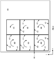
- FIG. 4 shows exemplary common line cutting for a nest of six rectangles.
- the plate 499 is to be cut to produce six identical rectangles, 420,430,440,450,460,470.
- edge of the plate 499 is not used, typically because the customer will not accept the plate edge as a part edge, although this is one variation explored later to save even more time and material.
- cutting of the plate 499 starts at 400 and proceeds with cutting edges 401,402,403, 404 to complete part 420 with four sides. Cutting then proceeding with edges 411, 412 and 413, which frees the second part 430 with cuts only to three sides. Starting on edge 421 in a clockwise direction, cutting of edges 422 and 423 frees the third part 440. Similarly, starting on edges 431, 432, 433, cutting frees the fourth part 450 with cuts to three edges of the rectangle. To cut part 460 requires cutting of only two edges 441 to 442, a two sided rectangle, and similarly with part 470.
- the direction of cut may be varied to minimize heat movement. So we have two clockwise cuts and four counter clockwise. As previously explained, this was expected to further degrade part quality as most plasma machines are setup to cut in only one direction.
- FIG. 5 shows exemplary common line cutting with casual partial overlap and non-rectangular parts.
- FIG. 5 illustrates the torch cutting paths and part edges are not drawn for clarity of illustration.
- Cutting starts at 501 and the cut progresses counter clockwise to free the first part 510.
- an edge start is required at 530 and cutting proceeds clockwise, ending at 540, since edge 550 is already cut.
- the savings here are far less in time and highly variable depending upon the amount of partial overlap. Determining the partial overlap, even for straight sides, makes for complex analysis.
- the edge start required to cut the second part 520 raises the specter of undesirable part damage.
- changing cut direction is also considered to produce unacceptable variations in part quality and size, so this type of cutting is unobserved. With the embodiments described herein, the changing cut direction and edge start is no-longer a concern or deterrent from cutting parts with partial overlap as shown in FIG. 5 .
- FIG. 6 shows a variation on the classic common cut nest. It differs in only one respect, the bottom and left straight edges of plate 600 are used as part boundaries. The area which is not cut is highlighted by dashed lines and it can be seen that there is a lot less cutting involved to separate the six parts from the plate.
- Cutting is less, with only 2 cuts per part.
- cutting lines 603 and 604 and the part is complete.
- each other part is completed by cutting pairs of edges 612, 613, 622, 623, 632, 633, 641, 642, 651, 652, respectively.
- Each part has only two cuts, requiring 50% of the traditional cutting, plus the fact that the remnant is a simple L shape with no scrap at all to handle.
- This sort of cutting makes use of the fact that the plate is often square cut, but does not rely on the exact dimensions as delivered plates are always over specification size, so only two edges may be trusted. This saving also requires either precise alignment on the start or a laser based alignment to rotate the programmed axes of the machine to match precisely those of the plate. This facility is increasingly common.
- FIG. 7 shows exemplary common cut circles with shared cut areas and use of the left and bottom plate edges.
- the nest for cutting four simple discs from plate 701 shown in FIG. 7 is a key example of how the disclosed embodiments overcome many of the previously accepted rules of NC plasma cutting.
- FIG. 7 shows cut width paths 701(1)-(4) of the torch, where the dashed lines represent an outer edge of the cut width and the solid line represents an inner edge of the cut width.
- the torch center and thus the entire plasma arc is off the plate while the inner edge of the cut path 701(2), or disc boundary, exactly touches the plate edge.
- the cutting starts at point 710 off the plate but adjacent to it. This is considered impossible in the prior art.
- the cutting paths completely overlap, raising major issues of increased cut width, torch extinguishing, increased edge damage and beveling, and excessive part movement as there is no skeleton to restrain hot parts.
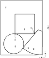
- FIG. 8 shows an even more extreme case of 'Common Kerf Cutting' as distinguished from 'Common Line Cutting' shown in FIGs. 4 & 6 .
- parts 802, 803, and 804 are nested such that their cut widths overlap completely at three touching points 810, 820, and 830. These areas are common cut only at these touching points.
- such nesting of parts with touch points was not done because of 'lost' or interruption of the plasma arc, expected very poor cutting in the overlap area, and even no cutting in the overlap area, and all the usual concerns as previously described.
- this type of nesting has great advantages over previous concepts and provides big savings in plate usage, when implemented as described in the embodiments hereof.
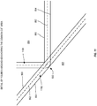
- FIG. 11 illustrates the complex area of cut path overlap at point 820 for parts 802 and 804 of FIG. 8 .
- a first cut path 1102 around part 802 has an internal contour 864, an external contour 860, and a dashed center line 862.
- a second cut path 1104, has an internal contour 850, an external contour 854, and a dashed center line 852.
- Each outer and inner contour 860, 854, 864, 850 is one kerf radius away from its center line 862, 852, respectively.
- the innermost shape of part 804 is rectangular, since the final shape required is a precise square.
- Inner shape contours 864, 850 form the future edges of parts 802 and 804. There is substantial significance in the radius of cutting path 1104 at location 820, since a square corner would actually penetrate shape 802, thereby destroying its contour integrity.
- contours 854 and 860 do not enter the part boundary of the adjacent parts 802 and 804 respectively.
- the value of making the corner of center line 852 at location 820 a radius is immediately apparent.
- many NC controls that are responsible for kerf compensation often do not use a radius but a straight line projection with a possible truncating line for very acute corners. In this way many existing NC controls are unsuitable for use with the embodiments disclosed herein, at least with kerf compensation that is calculated as a function of the NC control.
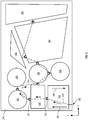
- FIG. 9 shows a more complex nest of fourteen parts having three quite different shapes and demonstrates the mix of common lines partially overlapped as 931 and full overlaps such as 932. It also demonstrates the use of the plate edge as part edges 950, 951, 952, which are not cut at all, thereby reducing cutting time. At locations 941, 942, and 940, the cutting torch center and thus the entire plasma arc actually leaves the plate 900. This is not an essential aspect of the invention though and an overlap is advisable to avoid the possibility of the plasma arc stopping unexpectedly.
- an edge start at 960 leads to cutting of part 901, and further edge and gap starts complete the nest including for example gap starts at 933, 934, 935, and edge starts at 940, 942, and 945.
- Dashed lines show the movements of the cutting torch from part to part without cutting. For example, when part 901 is completed, the torch is raised and proceeds to cut part 902 starting at the end of already cut line 931 with a gap start.
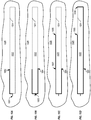
- FIGs. 10A-D show an exemplary sequence of cutting a long thin part 1022 using a cutting path 1024 from a plate 1020, a portion of which is shown, in stages with restart on the path and bi-directional cutting.
- thermal distortion produces movement based upon L 2 /W, it is not desired to cut too far along one side of the long thin part 1022, since the thermal difference would result in bending.
- such shapes were either not cut or were cut with two specially setup torches a fixed distance apart that cut two paths simultaneously to balance thermal movement.
- a cut is started at location 1001 and proceeds along cutting path 1024 to location 1002, where the plasma arc is stopped. Then, the cutting torch is moved to location 1003, restarted, and a cut is made along cutting path 1024 to location 1004 and the plasma arc is stopped. Then, the torch is moved back to location 1002, the plasma arc is restarted along the center of the cut path with a moving gap start, and cutting is resumed from location 1002 along cutting path 1024 to location 1005 where the plasma arc is stopped.
- the torch is moved back to location 1004, the plasma arc is restarted along the center of the cut path with a moving gap start, and cutting is resumed from location 1004 to location 1006, where the plasma arc is stopped.
- the final cut is made from location 1005 to location 1006 using a similar technique. While this takes five moves say, the end result should be a very straight long thin piece of steel and not one distorted and bent.
- the bending formula may be used to calculate a limit for an acceptable distance to cut on one side before stopping and cutting the other side.
- FIG. 12 is a flowchart illustrating one exemplary method 1200 for NC plasma common cutting of non-rectangular nested parts. Method 1200 is implemented in NC program generator 138 ofNC control 135 for example.
- step 1202 method 1200 receives a description of each of a plurality of parts to be cut from a workpiece.
- NC program generator 138 receives contours for each part 901-914 to be cut from workpiece 900.
- method 1200 determines a size and shape of the workpiece.
- the size and shape of workpiece is measured on NC cutting machine 140 using a laser measurement tool.
- NC program generator 138 receives data defining the shape and size of workpiece 900 from a user of NC control 135.
- step 1206 method 1200 generates a nest to optimally position the plurality of parts on the workpiece.
- NC program generator 138 uses method 1300 to generate nest 139 to position parts 901-914 on workpiece 900, optimizing based upon one or more of: minimize a number of pierce starts, maximize common line cutting, minimize overall cutting path by aligning contours of one or more parts with an edge of the work piece, and minimize waste of workpiece 900.
- method 1200 determines starting locations and stopping locations for a plasma arc of a cutting torch of an NC plasma cutting machine, the starting locations implementing one of an edge start and a gap start.
- NC program generator 138 determines locations for starting the plasma arc of cutting torch 120 based upon positioning of parts 901-914 within nest 139 relative to workpiece 900, wherein locations for edge starts are determined for parts having a contour proximate an edge of the workpiece, and locations for gap starts are determined for parts having a contour proximate a contour of a prior cut part. In another example of step 1208, NC program generator 138 determines locations for stopping the plasma arc based upon one or more of part contours, prior cut paths, and contours corresponding to workpiece edges.
- step 1210 method 1200 generates, based upon the nest and the determined locations for starting and stopping the plasma arc, an NC program to control the NC plasma cutting machine to cut the plurality of parts from the workpiece.
- NC program generator 138 generates NC program 136 based upon nest 139 and the determined starting and stopping locations of step 1208.
- Step 1212 is optional.
- method 1200 locates the workpiece on the NC cutting machine.
- an operator of NC cutting machine 140 positions and locates workpiece 900 on NC cutting machine 140.
- method 1200 executes the NC program on the NC controller to control the NC cutting machine to cut the plurality of parts from the workpiece.
- NC program generator 138 initiates execution of NC program 136 on NC control 135 to cut parts 901-914 from workpiece 900 on NC cutting machine 140.
- FIG. 13 is a flowchart illustrating one exemplary method 1300 for NC plasma common cutting of non-rectangular nested parts.
- Method 1300 is implemented within NC program generator 138 ofNC control 135 for example.
- Method 1300 has two possible starting points. Where the nest of parts has not been generated, method 1300 starts with step 1302 and then proceeds with step 1306. Where the nest of parts is already provided, method 1300 starts with step 1304 and then proceeds with step 1306.
- step 1302 method 1300 generates a nest of parts with part spacing equal to a cut width of the plasma cutting torch.
- NC program generator 138 generates nest 139 with parts 110 spaced from each other by only a cut width of plasma torch 120.
- step 1304 moves previously nested parts to reduce spacing between parts to a cut width.
- NC program generator 138 moves parts 110 within nest 139 to have a spacing of only a cut width of plasma torch 120. That is, NC program generator 138 pushes parts 110 together to have a separation of only a cut width or torch 120 in at least one place. Such spacing allows at least one location where a gap start may be used to start cutting an adjacent part after finishing a current part.
- step 1306 determines points of cut width spacing between adjacent parts.
- NC program generator 138 determines where two parts have only "cut width" spacing, where parts overlap with the plate edge, and where portions of cut paths for both parts overlap. For a particular part, these points are either double cut or not cut because they have been already cut when a previous part was cut, or are part of an edge of the workpiece.
- step 1308 breaks the contour for each part into contour portions based upon the points identified in step 1306. Given a desired sequence of cutting as defined by nest 139 for example, the external contour of each part is broken into portions based upon the points identified in step 1306.
- step 1310 method 1300 sequences the contour portions for each part such that the longest portion is cut last.
- NC program generator 138 sequences the portions determined in step 1308 such that the longest contour portion is cut last. This ensures that the entire part is not separated from the body of the remaining workpiece prematurely.
- step 1312 method 1300 sets the direction of cut for each contour portion to minimize thermal movement.
- NC program generator 138 sets the cut direction for each contour portion of step 1308 such that torch 120 cuts towards the greatest mass of remaining workpiece, and where necessary NC program generator 138 breaks the contour portion in to smaller portions.
- the external contour of each part 100 may be cut by either or both of clockwise and counterclockwise movements of torch 120.
- step 1314 method 1300 utilizes a gap start to start cutting each contour portion where possible.
- NC program generator 138 utilizes a gap start in a previously cut path corresponding to points identified in step 1306. Where sequencing is less than ideal and no previously cut part is within a cut width of the contour portion, where space permits a traditional pierce and entry is used to start the cut of the contour portion.
Landscapes
- Engineering & Computer Science (AREA)
- Physics & Mathematics (AREA)
- Mechanical Engineering (AREA)
- Plasma & Fusion (AREA)
- Human Computer Interaction (AREA)
- Manufacturing & Machinery (AREA)
- General Physics & Mathematics (AREA)
- Automation & Control Theory (AREA)
- Optics & Photonics (AREA)
- Arc Welding In General (AREA)
- Laser Beam Processing (AREA)
Claims (15)
- Procédé de découpe au plasma de pièces par commande numérique améliorée (NC) à partir d'une pièce, comprenant :la génération, sur un ordinateur, d'un quadrillage qui positionne les pièces de manière optimale afin de minimiser le gaspillage de la pièce (1206) ; etla génération, sur la base du quadrillage, d'un programme de commande numérique destiné à contrôler une machine de découpe au plasma à commande numérique destinée à découper les pièces à partir de la pièce à l'aide de l'un ou des deux de démarrages à partir d'un bord et de démarrage à partir d'un espace (1210) ;dans lequel le programme de commande numérique est capable de contrôler un chalumeau de découpe au plasma de la machine de découpe au plasma à commande numérique destinée à découper les pièces à partir de la pièce, dans lequel les pièces sont découpées à partir de la pièce à l'aide d'un chalumeau de découpe au plasma de la machine de découpe au plasma à commande numérique contrôlée par le programme de commande numérique (1214), caractérisé en ce que l'allumage de l'arc plasma du chalumeau de découpe au plasma a lieu pendant le mouvement latéral du chalumeau de découpe au plasma.
- Procédé selon la revendication 1, dans lequel, pour chaque démarrage à partir d'un bord, le programme de commande numérique allume un arc plasma du chalumeau de découpe au plasma lorsque le chalumeau de découpe au plasma est éteint et adjacent à un bord de la pièce, et permet un mouvement latéral immédiat du chalumeau de découpe.
- Procédé selon la revendication 1, dans lequel, pour chaque démarrage à partir d'un espace, le programme de commande numérique allume l'arc plasma lorsque le chalumeau de découpe au plasma est positionné par-dessus une découpe préalablement effectuée et permet un mouvement latéral immédiat du chalumeau de découpe.
- Procédé selon la revendication 3, dans lequel le chalumeau de découpe au plasma se déplace latéralement pendant que l'arc plasma est allumé.
- Procédé selon la revendication 1, l'étape de génération du quadrillage comprenant en outre le positionnement de toutes les pièces afin d'avoir une distance minimum entre les contours qui soit sensiblement égale à une largeur d'une seule découpe effectuée par le chalumeau de découpe au plasma.
- Procédé selon la revendication 1, l'étape de génération du quadrillage (1206) comprenant la génération du quadrillage afin de (a) minimiser la distance de découpe pour le quadrillage et/ou (b) maximiser la découpe sur une ligne commune, dans lequel au moins deux des pièces qui qui présentent des parties de contour formées de manière commune sont alignées l'une avec l'autre de sorte que les pièces soient séparées d'une largeur de découpe pour la partie à contour formée de manière commune.
- Procédé selon la revendication 1, l'étape de génération du quadrillage (1206) comprenant l'alignement d'une partie d'au moins l'une des pièces avec un ou plusieurs bords de la pièce.
- Procédé selon la revendication 7, l'étape de génération du programme de commande numérique (1210) comprenant la génération du programme de commande numérique afin d'utiliser un démarrage à partir d'un bord proche de la au moins une pièce afin de lancer la découpe de la pièce à partir de la pièce.
- Procédé selon la revendication 1, l'étape de génération du quadrillage (1206) comprenant le positionnement d'une première et d'une seconde des pièces sur le quadrillage de sorte que la découpe de la première pièce forme au moins une partie d'un bord de la seconde pièce, dans lequel la partie du bord est incurvée.
- Procédé selon la revendication 1, l'étape de génération du programme de commande numérique (1210) comprenant, pour un démarrage à partir d'un bord, la génération d'instructions destinées à : (a) positionner le chalumeau de découpe au plasma en position OFF et de manière adjacente à un bord de la pièce et près d'un contour de l'une des pièces, et (b) déclencher un arc du chalumeau de découpe au plasma pendant que le chalumeau de découpe se déplace parallèlement au bord avant de suivre le contour de façon à découper la pièce à partir de la pièce.
- Procédé selon la revendication 1, l'étape de génération du programme de commande numérique (1210) comprenant, pour un démarrage à partir d'un espace, la génération d'instructions destinées à : (a) positionner le chalumeau de découpe par-dessus un trajet préalablement découpé au sein de la pièce, et (b) déclencher un arc du chalumeau de découpe au plasma pendant que le chalumeau de découpe au plasma se déplace le long du trajet préalablement découpé, avant de suivre un contour d'une prochaine des pièces de façon à découper la pièce suivante à partir de la pièce.
- Procédé selon la revendication 1, l'étape de génération du programme de commande numérique (1210) comprenant la génération du programme de commande numérique afin d'arrêter l'arc du chalumeau de découpe au plasma pendant que le chalumeau de découpe au plasma se déplace.
- Procédé selon la revendication 1, l'étape de génération du programme de commande numérique (1210) comprenant la génération du programme de commande numérique afin d'arrêter un arc du chalumeau de découpe à un premier emplacement le long d'un contour d'au moins l'une des pièces, et afin de déclencher un arc du chalumeau de découpe à un second emplacement le long du contour et sur un côté opposé de la pièce de façon à minimiser le mouvement thermique de l'une ou des deux de (a) la pièce et (b) la au moins une pièce.
- Procédé selon la revendication 1, comprenant en outre la configuration d'un contrôleur à commande numérique de la machine de découpe à commande numérique afin d'exécuter un code M qui déplace le chalumeau de découpe au plasma latéralement pendant qu'un arc plasma du chalumeau de découpe au plasma s'allume.
- Procédé selon la revendication 1, comprenant en outre la configuration d'un contrôleur à commande numérique de la machine de découpe à commande numérique afin d'exécuter un code M qui déplace le chalumeau de découpe au plasma latéralement pendant qu'un arc plasma du chalumeau de découpe au plasma s'éteint.
Priority Applications (2)
| Application Number | Priority Date | Filing Date | Title |
|---|---|---|---|
| PL16160983T PL3078443T3 (pl) | 2015-03-20 | 2016-03-17 | Sposób i układ do ulepszonego sterowanego numerycznie cięcia plazmowego części z przedmiotu obrabianego |
| US15/088,800 US10195682B2 (en) | 2015-03-20 | 2016-04-01 | Method and system for enhanced numerical control plasma cutting of parts from a workpiece |
Applications Claiming Priority (1)
| Application Number | Priority Date | Filing Date | Title |
|---|---|---|---|
| US201562136237P | 2015-03-20 | 2015-03-20 |
Publications (2)
| Publication Number | Publication Date |
|---|---|
| EP3078443A1 EP3078443A1 (fr) | 2016-10-12 |
| EP3078443B1 true EP3078443B1 (fr) | 2019-10-16 |
Family
ID=55963134
Family Applications (1)
| Application Number | Title | Priority Date | Filing Date |
|---|---|---|---|
| EP16160983.9A Active EP3078443B1 (fr) | 2015-03-20 | 2016-03-17 | Procédé et système de commande numérique améliorée du découpage au plasma de pièces à partir d'une pièce à usiner |
Country Status (4)
| Country | Link |
|---|---|
| US (1) | US10195682B2 (fr) |
| EP (1) | EP3078443B1 (fr) |
| ES (1) | ES2760024T3 (fr) |
| PL (1) | PL3078443T3 (fr) |
Families Citing this family (28)
| Publication number | Priority date | Publication date | Assignee | Title |
|---|---|---|---|---|
| US10509390B2 (en) | 2015-02-12 | 2019-12-17 | Glowforge Inc. | Safety and reliability guarantees for laser fabrication |
| WO2016131018A1 (fr) | 2015-02-12 | 2016-08-18 | Glowforge Inc. | Aperçu visuel pour fabrication laser |
| JP6444923B2 (ja) * | 2016-03-30 | 2018-12-26 | ファナック株式会社 | 数値制御装置 |
| US10814668B2 (en) * | 2016-11-08 | 2020-10-27 | Jeffery James Jackson | Kiosk and method for making puzzle tags |
| US12420355B2 (en) | 2016-11-25 | 2025-09-23 | Glowforge Inc. | Laser fabrication with beam detection |
| WO2018098396A1 (fr) | 2016-11-25 | 2018-05-31 | Glowforge Inc. | Machine commandée numériquement par ordinateur multi-utilisateurs |
| WO2018098395A1 (fr) | 2016-11-25 | 2018-05-31 | Glowforge Inc. | Gravure améliorée dans une machine commandée numériquement par ordinateur |
| WO2018098399A1 (fr) | 2016-11-25 | 2018-05-31 | Glowforge Inc. | Décélération commandé de composants mobiles dans une machine à commande numérique par ordinateur |
| WO2018098393A1 (fr) | 2016-11-25 | 2018-05-31 | Glowforge Inc. | Boîtier pour machine à commande numérique par ordinateur |
| WO2018098397A1 (fr) | 2016-11-25 | 2018-05-31 | Glowforge Inc. | Calibrage d'une machine à commande numérique par ordinateur |
| WO2018098394A1 (fr) | 2016-11-25 | 2018-05-31 | Glowforge Inc. | Fabrication avec suivi d'image |
| WO2018098398A1 (fr) | 2016-11-25 | 2018-05-31 | Glowforge Inc. | Composants optiques prédéfinis dans une machine commandée numériquement par ordinateur |
| US10722974B2 (en) * | 2017-01-20 | 2020-07-28 | Hypertherm, Inc. | System and method for processing parts on a workpiece |
| JP6832731B2 (ja) * | 2017-02-08 | 2021-02-24 | 三菱電機株式会社 | レーザ加工機およびレーザ加工方法 |
| BE1025225B1 (nl) * | 2017-11-14 | 2018-12-06 | Metaalwerken Pamo Nv | Werkwijze en inrichting voor het vervaardigen van metalen constructies vanuit metalen platen en/of profielen en verkregen metalen constructie |
| DE112019001428A5 (de) * | 2018-03-21 | 2020-12-03 | Messer Cutting Systems Gmbh | Verfahren zum maschinellen thermischen Schneiden eines Werkstücks unter Einsatz eines Plasmaschneidbrenners |
| DE102018217200A1 (de) * | 2018-10-09 | 2020-04-09 | Trumpf Werkzeugmaschinen Gmbh + Co. Kg | Verfahren und Bearbeitungsmaschine zum Schneiden von Werkstücken sowie zugehöriges Computerprogrammprodukt |
| JP7277152B2 (ja) * | 2019-01-22 | 2023-05-18 | ファナック株式会社 | 工作機械の工具管理システム |
| JP7148421B2 (ja) | 2019-01-22 | 2022-10-05 | ファナック株式会社 | 工作機械の予防保全システム |
| CN110328441A (zh) * | 2019-08-06 | 2019-10-15 | 河北瓦尔丁科技有限公司 | 二托六数控等离子切割机 |
| US12059751B2 (en) * | 2020-03-27 | 2024-08-13 | Mitsubishi Electric Research Laboratories, Inc. | System and method for detecting and correcting laser-cutting distortion |
| WO2021224028A1 (fr) * | 2020-05-06 | 2021-11-11 | Seco Tools Ab | Pièce d'outil, système, procédé et programme informatique de détermination d'une dimension de la pièce d'outil |
| US11740608B2 (en) | 2020-12-24 | 2023-08-29 | Glowforge, Inc | Computer numerically controlled fabrication using projected information |
| CN112801944B (zh) * | 2020-12-31 | 2023-07-14 | 东莞材料基因高等理工研究院 | 一种改善慢走丝线切割机表面线痕的方法、装置及切割机 |
| US11698622B2 (en) | 2021-03-09 | 2023-07-11 | Glowforge Inc. | Previews for computer numerically controlled fabrication |
| CN113458538A (zh) * | 2021-07-22 | 2021-10-01 | 海阳中集来福士海洋工程有限公司 | 共边套料切割的方法 |
| US20240249037A1 (en) * | 2023-01-25 | 2024-07-25 | Hcl Technologies Limited | Nesting parts in 2-dimensional (2d) sheets by simultaneously using multiple pixel diagrams |
| CN116460935B (zh) * | 2023-04-25 | 2024-09-03 | 华闽搏创(成都)信息科技有限公司 | 基于消除板件移动的保持连接最大化的开料顺序方法 |
Family Cites Families (17)
| Publication number | Priority date | Publication date | Assignee | Title |
|---|---|---|---|---|
| US4466069A (en) | 1981-07-24 | 1984-08-14 | C-R-O, Inc. | Flame cutting machine with lost cut re-establishment |
| US6772040B1 (en) | 2000-04-10 | 2004-08-03 | Hypertherm, Inc. | Centralized control architecture for a plasma arc system |
| US7469620B2 (en) * | 2004-02-10 | 2008-12-30 | Matthew Fagan | Method and system for eliminating external piercing in NC cutting of nested parts |
| WO2007049751A1 (fr) | 2005-10-27 | 2007-05-03 | Komatsu Industries Corporation | Dispositif de coupe automatique et procede permettant de produire une piece biseautee |
| FR2896718B1 (fr) * | 2006-01-27 | 2008-03-07 | Airbus France Sas | Procede de decoupe d'une panoplie de pieces |
| PL1944113T3 (pl) | 2006-12-29 | 2016-03-31 | Matthew Fagan | Sposób, system i oprogramowanie do generowania obrysów wieloprzebiegowych i dzięki temu sterowania urządzeniem NC palników tnących w celu wycinania części z przygotowaniem do spawania |
| US8089024B2 (en) | 2007-09-19 | 2012-01-03 | Eigen Systems Limited | Torch spacing apparatus |
| US9539664B2 (en) | 2008-06-17 | 2017-01-10 | Matthew Fagan | Methods and systems for predictive torch height control |
| US8338739B2 (en) | 2008-12-22 | 2012-12-25 | Hypertherm, Inc. | Method and apparatus for cutting high quality internal features and contours |
| US8683841B1 (en) | 2009-01-20 | 2014-04-01 | Walsh Atkinson Co., Inc. | Apparatus and method to cut HVAC round and spiral ductwork and all attaching structures |
| US8395075B2 (en) | 2009-05-29 | 2013-03-12 | Kiffer Industries Inc. | Plasma torch cutting device and process |
| US9687933B2 (en) | 2009-06-10 | 2017-06-27 | Profile Cutting Systems Pty Ltd | Cutting head |
| WO2011042058A1 (fr) * | 2009-10-08 | 2011-04-14 | Tomologic Ab | Règles et variables de commande pour découpage |
| WO2011127601A1 (fr) * | 2010-04-13 | 2011-10-20 | National Research Council Of Canada | Procédé de commande d'un traitement par laser |
| US20110316977A1 (en) | 2010-06-24 | 2011-12-29 | Pienaar Marius G | Method of cnc profile cutting program manipulation |
| WO2012127319A1 (fr) | 2011-03-22 | 2012-09-27 | Matthew Fagan | Tête de chanfreinage pour commander un chalumeau coupeur pour couper une plaque avec préparation de soudage |
| US9469338B2 (en) * | 2011-04-07 | 2016-10-18 | Tomologic Ab | Method of, system and computer program for machine cutting several parts of a piece of material using controlling rules and variables for cutting |
-
2016
- 2016-03-17 PL PL16160983T patent/PL3078443T3/pl unknown
- 2016-03-17 EP EP16160983.9A patent/EP3078443B1/fr active Active
- 2016-03-17 ES ES16160983T patent/ES2760024T3/es active Active
- 2016-04-01 US US15/088,800 patent/US10195682B2/en active Active
Non-Patent Citations (1)
| Title |
|---|
| None * |
Also Published As
| Publication number | Publication date |
|---|---|
| US10195682B2 (en) | 2019-02-05 |
| ES2760024T3 (es) | 2020-05-12 |
| US20160271718A1 (en) | 2016-09-22 |
| EP3078443A1 (fr) | 2016-10-12 |
| PL3078443T3 (pl) | 2020-05-18 |
Similar Documents
| Publication | Publication Date | Title |
|---|---|---|
| US10195682B2 (en) | Method and system for enhanced numerical control plasma cutting of parts from a workpiece | |
| US9020628B2 (en) | Method and system for eliminating external piercing in NC cutting of nested parts | |
| US9469338B2 (en) | Method of, system and computer program for machine cutting several parts of a piece of material using controlling rules and variables for cutting | |
| US9108272B2 (en) | Controlling rules and variables for cutting | |
| US8987636B2 (en) | Method and system for multi pass weld preparation using a cutting torch | |
| WO2012063668A1 (fr) | Procédé d'usinage laser et dispositif d'usinage laser | |
| JP6980504B2 (ja) | 切断方法、切断プログラム、自動生成プログラム、制御システム、切断装置および被加工材の製造方法 | |
| KR101779021B1 (ko) | 판 부재의 천공 방법 | |
| JP2015057295A (ja) | カッティングのための制御ルールおよび変数 | |
| CN101885191A (zh) | 木工cnc加工中心工序的优化方法 | |
| JPH11192572A (ja) | レーザ加工機におけるピアス加工方法およびピアス加工開始位置制御装置 | |
| JP2025171483A (ja) | レーザ加工機、レーザ加工方法及びプログラム作成装置 | |
| JPH035088A (ja) | 板部材切断用数値制御プログラムの自動プログラミング装置および方法 | |
| KR20150136902A (ko) | 용접 구조물의 루즈 피스 시공방법 |
Legal Events
| Date | Code | Title | Description |
|---|---|---|---|
| PUAI | Public reference made under article 153(3) epc to a published international application that has entered the european phase |
Free format text: ORIGINAL CODE: 0009012 |
|
| AK | Designated contracting states |
Kind code of ref document: A1 Designated state(s): AL AT BE BG CH CY CZ DE DK EE ES FI FR GB GR HR HU IE IS IT LI LT LU LV MC MK MT NL NO PL PT RO RS SE SI SK SM TR |
|
| AX | Request for extension of the european patent |
Extension state: BA ME |
|
| STAA | Information on the status of an ep patent application or granted ep patent |
Free format text: STATUS: REQUEST FOR EXAMINATION WAS MADE |
|
| 17P | Request for examination filed |
Effective date: 20170407 |
|
| RBV | Designated contracting states (corrected) |
Designated state(s): AL AT BE BG CH CY CZ DE DK EE ES FI FR GB GR HR HU IE IS IT LI LT LU LV MC MK MT NL NO PL PT RO RS SE SI SK SM TR |
|
| GRAP | Despatch of communication of intention to grant a patent |
Free format text: ORIGINAL CODE: EPIDOSNIGR1 |
|
| STAA | Information on the status of an ep patent application or granted ep patent |
Free format text: STATUS: GRANT OF PATENT IS INTENDED |
|
| INTG | Intention to grant announced |
Effective date: 20190429 |
|
| RAP1 | Party data changed (applicant data changed or rights of an application transferred) |
Owner name: FAGAN, MATTHEW |
|
| RIN1 | Information on inventor provided before grant (corrected) |
Inventor name: FAGAN, MATTHEW |
|
| RAP1 | Party data changed (applicant data changed or rights of an application transferred) |
Owner name: FAGAN, MATTHEW |
|
| RIN1 | Information on inventor provided before grant (corrected) |
Inventor name: FAGAN, MATTHEW |
|
| GRAS | Grant fee paid |
Free format text: ORIGINAL CODE: EPIDOSNIGR3 |
|
| GRAA | (expected) grant |
Free format text: ORIGINAL CODE: 0009210 |
|
| STAA | Information on the status of an ep patent application or granted ep patent |
Free format text: STATUS: THE PATENT HAS BEEN GRANTED |
|
| AK | Designated contracting states |
Kind code of ref document: B1 Designated state(s): AL AT BE BG CH CY CZ DE DK EE ES FI FR GB GR HR HU IE IS IT LI LT LU LV MC MK MT NL NO PL PT RO RS SE SI SK SM TR |
|
| REG | Reference to a national code |
Ref country code: GB Ref legal event code: FG4D |
|
| REG | Reference to a national code |
Ref country code: CH Ref legal event code: EP |
|
| REG | Reference to a national code |
Ref country code: DE Ref legal event code: R096 Ref document number: 602016022414 Country of ref document: DE |
|
| REG | Reference to a national code |
Ref country code: IE Ref legal event code: FG4D |
|
| REG | Reference to a national code |
Ref country code: AT Ref legal event code: REF Ref document number: 1190808 Country of ref document: AT Kind code of ref document: T Effective date: 20191115 |
|
| REG | Reference to a national code |
Ref country code: NL Ref legal event code: MP Effective date: 20191016 |
|
| REG | Reference to a national code |
Ref country code: LT Ref legal event code: MG4D |
|
| REG | Reference to a national code |
Ref country code: AT Ref legal event code: MK05 Ref document number: 1190808 Country of ref document: AT Kind code of ref document: T Effective date: 20191016 |
|
| PG25 | Lapsed in a contracting state [announced via postgrant information from national office to epo] |
Ref country code: PT Free format text: LAPSE BECAUSE OF FAILURE TO SUBMIT A TRANSLATION OF THE DESCRIPTION OR TO PAY THE FEE WITHIN THE PRESCRIBED TIME-LIMIT Effective date: 20200217 Ref country code: BG Free format text: LAPSE BECAUSE OF FAILURE TO SUBMIT A TRANSLATION OF THE DESCRIPTION OR TO PAY THE FEE WITHIN THE PRESCRIBED TIME-LIMIT Effective date: 20200116 Ref country code: FI Free format text: LAPSE BECAUSE OF FAILURE TO SUBMIT A TRANSLATION OF THE DESCRIPTION OR TO PAY THE FEE WITHIN THE PRESCRIBED TIME-LIMIT Effective date: 20191016 Ref country code: LT Free format text: LAPSE BECAUSE OF FAILURE TO SUBMIT A TRANSLATION OF THE DESCRIPTION OR TO PAY THE FEE WITHIN THE PRESCRIBED TIME-LIMIT Effective date: 20191016 Ref country code: NO Free format text: LAPSE BECAUSE OF FAILURE TO SUBMIT A TRANSLATION OF THE DESCRIPTION OR TO PAY THE FEE WITHIN THE PRESCRIBED TIME-LIMIT Effective date: 20200116 Ref country code: GR Free format text: LAPSE BECAUSE OF FAILURE TO SUBMIT A TRANSLATION OF THE DESCRIPTION OR TO PAY THE FEE WITHIN THE PRESCRIBED TIME-LIMIT Effective date: 20200117 Ref country code: LV Free format text: LAPSE BECAUSE OF FAILURE TO SUBMIT A TRANSLATION OF THE DESCRIPTION OR TO PAY THE FEE WITHIN THE PRESCRIBED TIME-LIMIT Effective date: 20191016 Ref country code: SE Free format text: LAPSE BECAUSE OF FAILURE TO SUBMIT A TRANSLATION OF THE DESCRIPTION OR TO PAY THE FEE WITHIN THE PRESCRIBED TIME-LIMIT Effective date: 20191016 Ref country code: NL Free format text: LAPSE BECAUSE OF FAILURE TO SUBMIT A TRANSLATION OF THE DESCRIPTION OR TO PAY THE FEE WITHIN THE PRESCRIBED TIME-LIMIT Effective date: 20191016 Ref country code: AT Free format text: LAPSE BECAUSE OF FAILURE TO SUBMIT A TRANSLATION OF THE DESCRIPTION OR TO PAY THE FEE WITHIN THE PRESCRIBED TIME-LIMIT Effective date: 20191016 |
|
| REG | Reference to a national code |
Ref country code: ES Ref legal event code: FG2A Ref document number: 2760024 Country of ref document: ES Kind code of ref document: T3 Effective date: 20200512 |
|
| PG25 | Lapsed in a contracting state [announced via postgrant information from national office to epo] |
Ref country code: IS Free format text: LAPSE BECAUSE OF FAILURE TO SUBMIT A TRANSLATION OF THE DESCRIPTION OR TO PAY THE FEE WITHIN THE PRESCRIBED TIME-LIMIT Effective date: 20200224 Ref country code: HR Free format text: LAPSE BECAUSE OF FAILURE TO SUBMIT A TRANSLATION OF THE DESCRIPTION OR TO PAY THE FEE WITHIN THE PRESCRIBED TIME-LIMIT Effective date: 20191016 Ref country code: RS Free format text: LAPSE BECAUSE OF FAILURE TO SUBMIT A TRANSLATION OF THE DESCRIPTION OR TO PAY THE FEE WITHIN THE PRESCRIBED TIME-LIMIT Effective date: 20191016 |
|
| PG25 | Lapsed in a contracting state [announced via postgrant information from national office to epo] |
Ref country code: AL Free format text: LAPSE BECAUSE OF FAILURE TO SUBMIT A TRANSLATION OF THE DESCRIPTION OR TO PAY THE FEE WITHIN THE PRESCRIBED TIME-LIMIT Effective date: 20191016 |
|
| REG | Reference to a national code |
Ref country code: DE Ref legal event code: R097 Ref document number: 602016022414 Country of ref document: DE |
|
| PG2D | Information on lapse in contracting state deleted |
Ref country code: IS |
|
| PG25 | Lapsed in a contracting state [announced via postgrant information from national office to epo] |
Ref country code: EE Free format text: LAPSE BECAUSE OF FAILURE TO SUBMIT A TRANSLATION OF THE DESCRIPTION OR TO PAY THE FEE WITHIN THE PRESCRIBED TIME-LIMIT Effective date: 20191016 Ref country code: DK Free format text: LAPSE BECAUSE OF FAILURE TO SUBMIT A TRANSLATION OF THE DESCRIPTION OR TO PAY THE FEE WITHIN THE PRESCRIBED TIME-LIMIT Effective date: 20191016 Ref country code: CZ Free format text: LAPSE BECAUSE OF FAILURE TO SUBMIT A TRANSLATION OF THE DESCRIPTION OR TO PAY THE FEE WITHIN THE PRESCRIBED TIME-LIMIT Effective date: 20191016 Ref country code: RO Free format text: LAPSE BECAUSE OF FAILURE TO SUBMIT A TRANSLATION OF THE DESCRIPTION OR TO PAY THE FEE WITHIN THE PRESCRIBED TIME-LIMIT Effective date: 20191016 Ref country code: IS Free format text: LAPSE BECAUSE OF FAILURE TO SUBMIT A TRANSLATION OF THE DESCRIPTION OR TO PAY THE FEE WITHIN THE PRESCRIBED TIME-LIMIT Effective date: 20200216 |
|
| PLBE | No opposition filed within time limit |
Free format text: ORIGINAL CODE: 0009261 |
|
| STAA | Information on the status of an ep patent application or granted ep patent |
Free format text: STATUS: NO OPPOSITION FILED WITHIN TIME LIMIT |
|
| PG25 | Lapsed in a contracting state [announced via postgrant information from national office to epo] |
Ref country code: SM Free format text: LAPSE BECAUSE OF FAILURE TO SUBMIT A TRANSLATION OF THE DESCRIPTION OR TO PAY THE FEE WITHIN THE PRESCRIBED TIME-LIMIT Effective date: 20191016 Ref country code: SK Free format text: LAPSE BECAUSE OF FAILURE TO SUBMIT A TRANSLATION OF THE DESCRIPTION OR TO PAY THE FEE WITHIN THE PRESCRIBED TIME-LIMIT Effective date: 20191016 Ref country code: IT Free format text: LAPSE BECAUSE OF FAILURE TO SUBMIT A TRANSLATION OF THE DESCRIPTION OR TO PAY THE FEE WITHIN THE PRESCRIBED TIME-LIMIT Effective date: 20191016 |
|
| 26N | No opposition filed |
Effective date: 20200717 |
|
| PG25 | Lapsed in a contracting state [announced via postgrant information from national office to epo] |
Ref country code: MC Free format text: LAPSE BECAUSE OF FAILURE TO SUBMIT A TRANSLATION OF THE DESCRIPTION OR TO PAY THE FEE WITHIN THE PRESCRIBED TIME-LIMIT Effective date: 20191016 |
|
| REG | Reference to a national code |
Ref country code: CH Ref legal event code: PL |
|
| PG25 | Lapsed in a contracting state [announced via postgrant information from national office to epo] |
Ref country code: SI Free format text: LAPSE BECAUSE OF FAILURE TO SUBMIT A TRANSLATION OF THE DESCRIPTION OR TO PAY THE FEE WITHIN THE PRESCRIBED TIME-LIMIT Effective date: 20191016 |
|
| REG | Reference to a national code |
Ref country code: BE Ref legal event code: MM Effective date: 20200331 |
|
| PG25 | Lapsed in a contracting state [announced via postgrant information from national office to epo] |
Ref country code: LU Free format text: LAPSE BECAUSE OF NON-PAYMENT OF DUE FEES Effective date: 20200317 |
|
| PG25 | Lapsed in a contracting state [announced via postgrant information from national office to epo] |
Ref country code: CH Free format text: LAPSE BECAUSE OF NON-PAYMENT OF DUE FEES Effective date: 20200331 Ref country code: LI Free format text: LAPSE BECAUSE OF NON-PAYMENT OF DUE FEES Effective date: 20200331 Ref country code: IE Free format text: LAPSE BECAUSE OF NON-PAYMENT OF DUE FEES Effective date: 20200317 |
|
| PG25 | Lapsed in a contracting state [announced via postgrant information from national office to epo] |
Ref country code: BE Free format text: LAPSE BECAUSE OF NON-PAYMENT OF DUE FEES Effective date: 20200331 |
|
| GBPC | Gb: european patent ceased through non-payment of renewal fee |
Effective date: 20200317 |
|
| PG25 | Lapsed in a contracting state [announced via postgrant information from national office to epo] |
Ref country code: GB Free format text: LAPSE BECAUSE OF NON-PAYMENT OF DUE FEES Effective date: 20200317 |
|
| PG25 | Lapsed in a contracting state [announced via postgrant information from national office to epo] |
Ref country code: TR Free format text: LAPSE BECAUSE OF FAILURE TO SUBMIT A TRANSLATION OF THE DESCRIPTION OR TO PAY THE FEE WITHIN THE PRESCRIBED TIME-LIMIT Effective date: 20191016 Ref country code: MT Free format text: LAPSE BECAUSE OF FAILURE TO SUBMIT A TRANSLATION OF THE DESCRIPTION OR TO PAY THE FEE WITHIN THE PRESCRIBED TIME-LIMIT Effective date: 20191016 Ref country code: CY Free format text: LAPSE BECAUSE OF FAILURE TO SUBMIT A TRANSLATION OF THE DESCRIPTION OR TO PAY THE FEE WITHIN THE PRESCRIBED TIME-LIMIT Effective date: 20191016 |
|
| PG25 | Lapsed in a contracting state [announced via postgrant information from national office to epo] |
Ref country code: MK Free format text: LAPSE BECAUSE OF FAILURE TO SUBMIT A TRANSLATION OF THE DESCRIPTION OR TO PAY THE FEE WITHIN THE PRESCRIBED TIME-LIMIT Effective date: 20191016 |
|
| P01 | Opt-out of the competence of the unified patent court (upc) registered |
Effective date: 20230512 |
|
| PGFP | Annual fee paid to national office [announced via postgrant information from national office to epo] |
Ref country code: ES Payment date: 20250408 Year of fee payment: 10 |
|
| PGFP | Annual fee paid to national office [announced via postgrant information from national office to epo] |
Ref country code: DE Payment date: 20260310 Year of fee payment: 11 |
|
| PGFP | Annual fee paid to national office [announced via postgrant information from national office to epo] |
Ref country code: FR Payment date: 20260323 Year of fee payment: 11 |
|
| PGFP | Annual fee paid to national office [announced via postgrant information from national office to epo] |
Ref country code: PL Payment date: 20260317 Year of fee payment: 11 |