EP3078557B1 - Längenänderungselement mit piezoaktor und fahrzeug mit abs-bremssystem - Google Patents
Längenänderungselement mit piezoaktor und fahrzeug mit abs-bremssystem Download PDFInfo
- Publication number
- EP3078557B1 EP3078557B1 EP16154960.5A EP16154960A EP3078557B1 EP 3078557 B1 EP3078557 B1 EP 3078557B1 EP 16154960 A EP16154960 A EP 16154960A EP 3078557 B1 EP3078557 B1 EP 3078557B1
- Authority
- EP
- European Patent Office
- Prior art keywords
- vehicle
- end region
- region
- piezo actuator
- change element
- Prior art date
- Legal status (The legal status is an assumption and is not a legal conclusion. Google has not performed a legal analysis and makes no representation as to the accuracy of the status listed.)
- Active
Links
Images

Classifications
-
- B—PERFORMING OPERATIONS; TRANSPORTING
- B60—VEHICLES IN GENERAL
- B60T—VEHICLE BRAKE CONTROL SYSTEMS OR PARTS THEREOF; BRAKE CONTROL SYSTEMS OR PARTS THEREOF, IN GENERAL; ARRANGEMENT OF BRAKING ELEMENTS ON VEHICLES IN GENERAL; PORTABLE DEVICES FOR PREVENTING UNWANTED MOVEMENT OF VEHICLES; VEHICLE MODIFICATIONS TO FACILITATE COOLING OF BRAKES
- B60T11/00—Transmitting braking action from initiating means to ultimate brake actuator without power assistance or drive or where such assistance or drive is irrelevant
- B60T11/04—Transmitting braking action from initiating means to ultimate brake actuator without power assistance or drive or where such assistance or drive is irrelevant transmitting mechanically
- B60T11/046—Using cables
-
- B—PERFORMING OPERATIONS; TRANSPORTING
- B60—VEHICLES IN GENERAL
- B60T—VEHICLE BRAKE CONTROL SYSTEMS OR PARTS THEREOF; BRAKE CONTROL SYSTEMS OR PARTS THEREOF, IN GENERAL; ARRANGEMENT OF BRAKING ELEMENTS ON VEHICLES IN GENERAL; PORTABLE DEVICES FOR PREVENTING UNWANTED MOVEMENT OF VEHICLES; VEHICLE MODIFICATIONS TO FACILITATE COOLING OF BRAKES
- B60T13/00—Transmitting braking action from initiating means to ultimate brake actuator with power assistance or drive; Brake systems incorporating such transmitting means, e.g. air-pressure brake systems
- B60T13/74—Transmitting braking action from initiating means to ultimate brake actuator with power assistance or drive; Brake systems incorporating such transmitting means, e.g. air-pressure brake systems with electrical assistance or drive
- B60T13/746—Transmitting braking action from initiating means to ultimate brake actuator with power assistance or drive; Brake systems incorporating such transmitting means, e.g. air-pressure brake systems with electrical assistance or drive and mechanical transmission of the braking action
-
- B—PERFORMING OPERATIONS; TRANSPORTING
- B60—VEHICLES IN GENERAL
- B60T—VEHICLE BRAKE CONTROL SYSTEMS OR PARTS THEREOF; BRAKE CONTROL SYSTEMS OR PARTS THEREOF, IN GENERAL; ARRANGEMENT OF BRAKING ELEMENTS ON VEHICLES IN GENERAL; PORTABLE DEVICES FOR PREVENTING UNWANTED MOVEMENT OF VEHICLES; VEHICLE MODIFICATIONS TO FACILITATE COOLING OF BRAKES
- B60T8/00—Arrangements for adjusting wheel-braking force to meet varying vehicular or ground-surface conditions, e.g. limiting or varying distribution of braking force
- B60T8/17—Using electrical or electronic regulation means to control braking
- B60T8/1701—Braking or traction control means specially adapted for particular types of vehicles
- B60T8/1706—Braking or traction control means specially adapted for particular types of vehicles for single-track vehicles, e.g. motorcycles
-
- H—ELECTRICITY
- H02—GENERATION; CONVERSION OR DISTRIBUTION OF ELECTRIC POWER
- H02N—ELECTRIC MACHINES NOT OTHERWISE PROVIDED FOR
- H02N2/00—Electric machines in general using piezoelectric effect, electrostriction or magnetostriction
- H02N2/02—Electric machines in general using piezoelectric effect, electrostriction or magnetostriction producing linear motion, e.g. actuators; Linear positioners ; Linear motors
- H02N2/04—Constructional details
- H02N2/043—Mechanical transmission means, e.g. for stroke amplification
-
- F—MECHANICAL ENGINEERING; LIGHTING; HEATING; WEAPONS; BLASTING
- F16—ENGINEERING ELEMENTS AND UNITS; GENERAL MEASURES FOR PRODUCING AND MAINTAINING EFFECTIVE FUNCTIONING OF MACHINES OR INSTALLATIONS; THERMAL INSULATION IN GENERAL
- F16D—COUPLINGS FOR TRANSMITTING ROTATION; CLUTCHES; BRAKES
- F16D2125/00—Components of actuators
- F16D2125/18—Mechanical mechanisms
- F16D2125/58—Mechanical mechanisms transmitting linear movement
- F16D2125/60—Cables or chains, e.g. Bowden cables
-
- F—MECHANICAL ENGINEERING; LIGHTING; HEATING; WEAPONS; BLASTING
- F16—ENGINEERING ELEMENTS AND UNITS; GENERAL MEASURES FOR PRODUCING AND MAINTAINING EFFECTIVE FUNCTIONING OF MACHINES OR INSTALLATIONS; THERMAL INSULATION IN GENERAL
- F16D—COUPLINGS FOR TRANSMITTING ROTATION; CLUTCHES; BRAKES
- F16D2129/00—Type of operation source for auxiliary mechanisms
- F16D2129/06—Electric or magnetic
- F16D2129/12—Electrostrictive or magnetostrictive elements, e.g. piezoelectric
Definitions
- the present invention relates to a cable of a brake system of a vehicle comprising a length change element with a piezo actuator.
- the present invention also relates to a vehicle, in particular an electric bicycle, with an anti-lock braking system (ABS).
- ABS anti-lock braking system
- the DE 102013213413 A discloses an electric bicycle with a brake system, the brake system comprising a cable with a length change element.
- ABS brake systems are also known for two-wheelers, in particular also for electric bicycles.
- the DE102012222048A1 a control unit for controlling a braking system of a two-wheeler, which is intended to prevent a rollover during a braking process of the two-wheeler.
- ABS brake systems have not yet established themselves or are not yet suitable for the masses, in particular for reasons of cost. From a safety point of view in particular, however, it would be desirable if a large number of two-wheelers could be equipped with an anti-lock braking system.
- the length change element comprises a piezo actuator with an actuator base and an actuator head.
- the length change element has a first and a second end area, the first end area being connected to the actuator head and the second end area being connected to the actuator base.
- there is at least one first Connecting arm is provided which connects the first end region of the length change element to the second end region.
- the change in length can be an extension or a shortening of the length change element.
- the length change element is suitable for being integrated into a brake system and, in particular, being integrated into an anti-lock braking system.
- the first connecting arm preferably has a connection area for fixing an object.
- the length change element according to the invention can particularly preferably be used in connection with a cable pull, so that a cable pull is preferably fixed at the connection area.
- connection area on the first connecting arm is preferably arranged in the middle of the first connecting arm.
- the first connecting arm is preferably fixed at a point of articulation on the first end region and is fixed to a second point of articulation on the second end region. Furthermore, the connection area is arranged on a first side of a line comprising the first and second articulation points and the piezo actuator of the length change element is arranged on a second side of the line opposite the first side.
- connection area and the piezo actuator are arranged on a second side of the line which connects the first and second articulation points.
- a length change element can be implemented which, when the piezo actuator is elongated, enables it to be shortened when used with a cable pull.
- the piezo actuator preferably has a structure such that the length of the piezo actuator is only changed at the actuator head. As a result, the actuator base can remain stationary on the length change element.
- the first connecting space is made from a material with inherent elasticity, for example from spring steel or from plastic.
- the length change element further preferably comprises a second connecting arm, which is fixed on the first end area of the length change element at a third articulation point and is fixed on the second end area of the length change element at a fourth articulation point.
- the second connecting arm is arranged opposite the first connecting arm.
- a length change element can be implemented which has a trapezoidal shape with a central region on which the piezo actuator is arranged.
- the length change element is preferably designed symmetrically to a longitudinal axis of the piezo actuator.
- the present invention relates to a cable of a brake system of a vehicle which comprises a first cable area and a length change element according to the invention, the length change element being arranged at the end of the first cable area.
- the cable pull particularly preferably comprises a first cable area and a second cable area, the length change element being arranged between the first and second cable areas.
- the first cable area is preferably arranged on the first connection area of the length change element and the second cable area is arranged on the second connection area of the length change element.
- the present invention further relates to a vehicle that can be driven with muscle power and motor power, in particular an electric bicycle, comprising an electric drive, a power supply unit and a cable according to the invention.
- the length change element is particularly preferably arranged on or in the electric drive of the vehicle. Particularly preferably, a robust and space-saving structure can be implemented by integrating the length change element into the electric drive.
- the piezo actuator of the length change element is furthermore preferably connected to the power supply of the vehicle. This enables a safe and simple power supply to be implemented for the piezo actuator.
- the vehicle according to the invention preferably further comprises a control unit and a sensor for detecting a speed on a wheel of the vehicle.
- the control unit is set up to activate the piezo actuator when the vehicle is braking in order to bring about a change in length of the length change element when a wheel of the vehicle is blocked and the wheel is unblocked by the change in length of the length change element.
- a simple anti-lock braking system control can be implemented which makes braking the vehicle safer, in particular in the case of a two-wheeled vehicle, in particular an electric bicycle.
- a sensor for detecting the rotational speed is arranged on a rear wheel and / or on a front wheel on the vehicle according to the invention.
- the present invention also relates to the use of a length change element with a piezo actuator in a cable brake system of a vehicle.
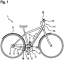
- the electric bicycle 1 comprises a crank drive 2 and an electric drive 3, which is arranged in the area of the crank drive 2.
- the electric bicycle 1 also comprises a chain 5 and a plurality of pinions 6 on a rear wheel 9.
- the reference numeral 4 denotes a power supply device.
- Cranks of the crank drive 2 are denoted by the reference numerals 7 and 8.
- the electric drive 3 is supplied with power from the power supply device 4.
- the power supply device 4 also supplies the control unit 10 with electrical energy.
- the Figures 2 and 3 show the length change element 20 according to the invention. As in particular from FIG Figure 3 As can be seen, the length change element 20 has a trapezoidal shape in a side view.
- the length change element 20 comprises a first end region 21 and a second end region 22, between which a piezo actuator 23 is arranged.
- the piezo actuator 23 comprises an actuator base 24 and an actuator head 25.
- a first connecting arm 26 connects the first end area 21 to the second end area 22.
- a second connecting arm 27 also connects the first end area 21 to the second end area 22.
- the connecting arms are provided in such a way that in side view when the length change element 20 is in rest position, a symmetrical trapezoidal shape is obtained.
- a first connection area 28 for fixing the first cable area 14 on the length change element 20 is arranged on the first connecting arm 26.
- the second connecting arm 27 has a second connection area 29 for fixing the second cable area 15 on the length change element 20.
- the length change element 20 is thus arranged between two cable areas 14, 15 of the cable of a brake system 11 of the electric bicycle.
- the brake system 11 further comprises a speed sensor 12 which is arranged on the rear wheel 9.
- a brake lever 13 is provided on the handlebar in a known manner in order to actuate the rear wheel brake 16.
- a speed sensor is preferably also provided on the front wheel and a brake lever for a front wheel brake.
- the length change element 20 is integrated into the electric drive 3.
- the length change element 20 is supplied with power by the power supply device 4 of the electric bicycle.
- the change in length of the length change element 20 takes place in such a way that when the piezo actuator 23 is activated, the actuator head 25 is elongated in the direction of arrow A.
- the extension of the piezo actuator 23 also results in an extension of the length change element 20 in the direction of the arrow B, as in FIG Figure 3 drawn.
- the length change element 20 comes from the in Figure 3 in the starting position drawn in crossed lines to the in Figure 3 shown, shown in dashed lines, shortened position.
- a position of the first connecting arm 26 is denoted by the reference numeral 26 'and a position of the second connecting arm 27 is denoted by the reference numeral 27'.
- the two connecting arms 26, 27 therefore move due to an extension of the piezo actuator 23 in the direction of the piezo actuator 23, which is indicated by the arrows C.
- first connecting arm 26 and the second connecting arm 27 are on a first side of a line L1, which connects the first articulation point 31 to the second articulation point 32, and a line L2, which connects the third articulation point 33 to the fourth articulation point 34 , arranged on a side facing away from the piezo actuator 23.
- a shortening of the length change element 20 thus also means a tightening of the second cable area 15 in the direction of the first cable area 14, so that a braking force on the rear wheel brake 16 is reduced when the brake is released by pulling.
- the length change element 20 can be used in conjunction with an anti-lock braking system.
- the control unit 10 is set up in such a way that when a wheel blockage on the rear wheel 9 is detected by means of the sensor 12, which is, for example, a speed sensor, the control unit 10 actuates the piezo actuator 23 so that the length change element 20 is shortened.
- the braking force on the rear wheel brake 16 is reduced, so that a blockage of the rear wheel 9 is ended.
- a control loop can now be activated, since the sensor 12 on the rear wheel 9 now detects a rotation of the rear wheel 9 again.
- the control unit 10 can deactivate the piezo actuator 23 again, so that an extension of the cable pull occurs again, since the length change element 20 due to its inherent elasticity back into its in Figure 2 shown starting position returns.
- An anti-lock braking system for an electric bicycle 1 can thus be implemented by means of an inexpensive length change element 20 in a cable pull.
- the length change element 20 is very compact and can preferably be integrated into the electric drive 3. It is thus possible for electric bicycles to be mass-fitted with anti-lock braking systems in a cost-effective and compact manner.
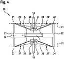
- Figure 4 shows a length change element 20 according to a second embodiment of the invention.
- the length change element 20 is lengthened. This is achieved in that the first connecting arm 26 and the second connecting arm 27 are arranged on a second side of the lines L1 and L2 connecting the articulation points.
- the cable pull is also lengthened, since the first and second connection areas 28, 29, as in FIG Figure 4 indicated by the arrows D, are moved in the direction away from the piezo actuator 23.
- An extension of the cable pull can thus also be implemented in a simple manner.
- the deflected position of the length change element 20 is again shown in dashed lines.
- the inventive use of the connecting arms 26, 27 thus also results in a translation of the stroke of the piezo actuator 23 of a few millimeters, as can be seen from the Figures 3 and 4th can be seen.
- an extension of the piezo actuator 23 when it is activated is approximately 35 to 60 ⁇ m. Since the piezo actuator 23 has only a very small electrical power consumption, a range of an electric bicycle in particular is not significantly reduced. Furthermore, a very exact and rapid change in length of the length change element 20 can be carried out by means of the piezo actuator 23, so that the control unit 10 can implement a very good ABS regulation.
Landscapes
- Engineering & Computer Science (AREA)
- Transportation (AREA)
- Mechanical Engineering (AREA)
- Regulating Braking Force (AREA)
Description
- Die vorliegende Erfindung betrifft ein Seilzug einer Bremsanlage eines Fahrzeugs umfassend ein Längenänderungselement mit einem Piezoaktor. Ferner betrifft die vorliegende Erfindung ein Fahrzeug, insbesondere ein Elektrofahrrad, mit einem Antiblockiersystem (ABS).
- Die
DE 102013213413 A offenbart ein elektrisches Fahrrad mit einer Bremsanlage, wobei die Bremsanlage einen Seilzug mit einem Längenänderungselement umfasst. - Grundsätzlich sind ABS-Bremsanlagen auch bei Zweirädern, insbesondere auch bei Elektrofahrrädern, bekannt. Beispielsweise zeigt die
DE102012222048A1 eine Steuereinheit zum Steuern eines Bremssystems eines Zweirads, welches einen Überschlag bei einem Bremsvorgang des Zweirads verhindern soll. Insbesondere für Elektrofahrräder haben sich bisher jedoch ABS-Bremsanlagen insbesondere aus Kostengründen noch nicht durchgesetzt bzw. sind noch nicht massentauglich. Insbesondere aus sicherheitstechnischen Aspekten wäre es allerdings wünschenswert, wenn eine Vielzahl von Zweirädern mit einem Antiblockiersystem ausgestattet werden könnte. - Der erfindungsgemäße Seilzug mit einem Längenänderungselement mit den Merkmalen des Anspruchs 1 weist demgegenüber den Vorteil auf, dass es einen kostengünstigen und einfachen sowie robusten Aufbau aufweist. Dadurch ist es geeignet, beispielsweise in Bremsanlagen von Zweirädern, insbesondere Elektrofahrrädern, verwendet zu werden. Erfindungsgemäß umfasst das Längenänderungselement einen Piezoaktor mit einem Aktorfuß und einem Aktorkopf. Das Längenänderungselement weist einen ersten und einen zweiten Endbereich auf, wobei der erste Endbereich mit dem Aktorkopf und der zweite Endbereich mit dem Aktorfuß verbunden ist. Ferner ist wenigstens ein erster Verbindungsarm vorgesehen, welcher den ersten Endbereich des Längenänderungselements mit dem zweiten Endbereich verbindet. Erfindungsgemäß wird dadurch erreicht, dass eine Auslenkung des ersten Verbindungsarms möglich ist, um eine Längenänderung des Längenänderungselements zu ermöglichen. Die Längenänderung kann dabei eine Verlängerung oder auch eine Verkürzung des Längenänderungselements sein. Dadurch ist das Längenänderungselement geeignet, in eine Bremsanlage integriert zu werden und insbesondere in ein Antiblockiersystem integriert zu werden.
- Die Unteransprüche zeigen bevorzugte Weiterbildungen der Erfindung.
- Vorzugsweise weist der erste Verbindungsarm einen Anschlussbereich zur Fixierung eines Gegenstands auf. Besonders bevorzugt ist das erfindungsgemäße Längenänderungselement in Verbindung mit einem Seilzug nutzbar, so dass am Anschlussbereich vorzugsweise ein Seilzug fixiert ist.
- Der Anschlussbereich am ersten Verbindungsarm ist vorzugsweise in der Mitte des ersten Verbindungsarms angeordnet. Dadurch kann eine gleichmäßige Belastung des Längenänderungselements hinsichtlich Zugkräften und Druckkräften erreicht werden.
- Bevorzugt ist der erste Verbindungsarm am ersten Endbereich an einem Anlenkpunkt fixiert und am zweiten Endbereich an einem zweiten Anlenkpunkt fixiert. Ferner ist der Anschlussbereich an einer ersten Seite einer den ersten und zweiten Anlenkpunkt umfassenden Linie angeordnet und der Piezoaktor des Längenänderungselements ist an einer der ersten Seite gegenüberliegenden zweiten Seite der Linie angeordnet. Dadurch kann bei Verwendung eines Seilzugs, welcher am Anschlussbereich fixiert ist, durch eine Längenänderung des Piezoaktors eine Verkürzung einer Seillänge erreicht werden.
- Alternativ sind der Anschlussbereich und der Piezoaktor an einer zweiten Seite der Linie, welche den ersten und zweiten Anlenkpunkt verbindet, angeordnet. Dadurch kann ein Längenänderungselement realisiert werden, welches bei einer Längung des Piezoaktors eine Verkürzung bei Verwendung bei einem Seilzug ermöglicht.
- Vorzugsweise weist der Piezoaktor einen Aufbau derart auf, dass eine Längenänderung des Piezoaktors nur am Aktorkopf ausgeführt wird. Dadurch kann der Aktorfuß ortsfest am Längenänderungselement verbleiben.
- Gemäß einer weiteren bevorzugten Ausgestaltung der vorliegenden Erfindung ist der erste Verbindungsraum aus einem Material mit einer Eigenelastizität hergestellt, beispielsweise aus Federstahl oder aus Kunststoff. Nach einer erfolgten Auslenkung des Längenänderungselements durch den Piezoaktor erfolgt dadurch eine selbstständige Rückstellung des Längenänderungselements in eine Ausgangsposition. Dadurch muss kein Rückstellelement oder dgl. vorgesehen werden.
- Weiter bevorzugt umfasst das Längenänderungselement einen zweiten Verbindungsarm, welcher am ersten Endbereich des Längenänderungselements an einem dritten Anlenkpunkt fixiert ist und am zweiten Endbereich des Längenänderungselements an einem vierten Anlenkpunkt fixiert ist. Der zweite Verbindungsarm ist dabei gegenüber dem ersten Verbindungsarm angeordnet. Dadurch kann beispielsweise ein Längenänderungselement realisiert werden, welches eine Trapezform mit einem Mittelbereich, an welchem der Piezoaktor angeordnet ist, aufweist. Das Längenänderungselement ist dabei bevorzugt symmetrisch zu einer Längsachse des Piezoaktors ausgebildet.
- Die vorliegende Erfindung betrifft einen Seilzug einer Bremsanlage eines Fahrzeugs, welche einen ersten Seilbereich und ein erfindungsgemäßes Längenänderungselement umfasst, wobei das Längenänderungselement am Ende des ersten Seilbereichs angeordnet ist.
- Besonders bevorzugt umfasst der Seilzug einen ersten Seilbereich und einen zweiten Seilbereich, wobei das Längenänderungselement zwischen dem ersten und zweiten Seilbereich angeordnet ist. Bevorzugt ist dabei der erste Seilbereich am ersten Anschlussbereich des Längenänderungselements angeordnet und der zweite Seilbereich am zweiten Anschlussbereich des Längenänderungselements angeordnet.
- Ferner betrifft die vorliegende Erfindung ein mit Muskelkraft und Motorkraft antreibbares Fahrzeug, insbesondere ein Elektrofahrrad, umfassend einen elektrischen Antrieb, eine Stromversorgungseinheit und einen erfindungsgemäßen Seilzug.
- Besonders bevorzugt ist dabei das Längenänderungselement am oder im elektrischen Antrieb des Fahrzeugs angeordnet. Besonders bevorzugt kann durch eine Integration des Längenänderungselements in den elektrischen Antrieb ein robuster und platzsparender Aufbau realisiert werden. Weiter bevorzugt ist der Piezoaktor des Längenänderungselements mit der Stromversorgung des Fahrzeugs verbunden. Dadurch kann eine sichere und einfache Stromversorgung des Piezoaktors realisiert werden.
- Weiterhin umfasst bevorzugt das erfindungsgemäße Fahrzeug ferner eine Steuereinheit und einen Sensor zur Erfassung einer Drehzahl an einem Rad des Fahrzeugs. Die Steuereinheit ist dabei eingerichtet, bei einem Bremsvorgang des Fahrzeugs den Piezoaktor zu aktivieren, um eine Längenänderung des Längenänderungselements zu bewirken, wenn ein Rad des Fahrzeugs blockiert und die Blockade des Rades durch die Längenänderung des Längenänderungselements aufgehoben wird. Hierdurch kann eine einfache Antiblockiersystemsteuerung realisiert werden, welche einen Bremsvorgang des Fahrzeugs sicherer macht, insbesondere bei einem zweirädrigen Fahrzeug, insbesondere einem Elektrofahrrad.
- Ferner ist am erfindungsgemäßen Fahrzeug ein Sensor zur Drehzahlerfassung an einem Hinterrad und/oder an einem Vorderrad angeordnet.
- Weiterhin betrifft die vorliegende Erfindung eine Verwendung eines Längenänderungselements mit Piezoaktor in einer Seilzug-Bremsanlage eines Fahrzeugs.
- Nachfolgend werden bevorzugte Ausführungsbeispiele der Erfindung unter Bezugnahme auf die begleitende Zeichnung im Detail beschrieben. In der Zeichnung sind gleiche bzw. funktional gleiche Teile mit den gleichen Bezugszeichen bezeichnet. In der Zeichnung ist:
- Figur 1
- eine schematische Ansicht eines Elektrofahrrads mit einem erfindungsgemäßen Längenänderungselements gemäß einem ersten Ausführungsbeispiel der Erfindung,
- Figur 2
- eine schematische, perspektivische Ansicht des Längenänderungselements des ersten Ausführungsbeispiels,
- Figur 3
- eine schematische Seitenansicht des Längenänderungselements von
Figur 2 , und - Figur 4
- eine schematische Seitenansicht eines Längenänderungselements gemäß einem zweiten Ausführungsbeispiel der Erfindung.
- Nachfolgend wird unter Bezugnahme auf die
Figuren 1 bis 3 ein Elektrofahrrad 1 mit einem Längenänderungselement 20 gemäß einem ersten bevorzugten Ausführungsbeispiel der Erfindung im Detail beschrieben. - Das Elektrofahrrad 1 umfasst einen Kurbeltrieb 2 und einen elektrischen Antrieb 3, welcher im Bereich des Kurbeltriebs 2 angeordnet ist. Das Elektrofahrrad 1 umfasst ferner eine Kette 5 sowie mehrere Ritzel 6 an einem Hinterrad 9. Das Bezugszeichen 4 bezeichnet eine Stromversorgungseinrichtung. Kurbeln des Kurbeltriebs 2 sind mit den Bezugszeichen 7 und 8 bezeichnet.
- Der elektrische Antrieb 3 wird von der Stromversorgungseinrichtung 4 mit Strom versorgt. Am Lenker des Elektrofahrrads 1 ist ferner eine Steuereinheit 10 vorgesehen, welche mit dem elektrischen Antrieb 3 verbunden ist und diesen steuert. Die Stromversorgungseinrichtung 4 versorgt dabei die Steuereinheit 10 ebenfalls mit elektrischer Energie.
- Die
Figuren 2 und 3 zeigen das erfindungsgemäße Längenänderungselement 20. Wie insbesondere ausFigur 3 ersichtlich ist, weist das Längenänderungselement 20 in Seitenansicht eine Trapezform auf. - Das Längenänderungselement 20 umfasst einen ersten Endbereich 21 und einen zweiten Endbereich 22, zwischen welchen ein Piezoaktor 23 angeordnet ist. Der Piezoaktor 23 umfasst einen Aktorfuß 24 und einen Aktorkopf 25.
- Ein erster Verbindungsarm 26 verbindet dabei den ersten Endbereich 21 mit dem zweiten Endbereich 22. Ein zweiter Verbindungsarm 27 verbindet ebenfalls den ersten Endbereich 21 mit dem zweiten Endbereich 22. Die Verbindungsarme sind dabei derart vorgesehen, dass in Seitenansicht in Ruhelage des Längenänderungselements 20 eine symmetrische Trapezform erhalten wird.
- Am ersten Verbindungsarm 26 ist ein erster Anschlussbereich 28 zum Fixieren des ersten Seilbereichs 14 am Längenänderungselement 20 angeordnet. Der zweite Verbindungsarm 27 weist einen zweiten Anschlussbereich 29 zum Fixieren des zweiten Seilbereichs 15 am Längenänderungselement 20 auf.
- Somit ist das Längenänderungselement 20 zwischen zwei Seilbereichen 14, 15 des Seilzugs einer Bremsanlage 11 des Elektrofahrrads angeordnet.
- Die Bremsanlage 11 umfasst ferner einen Drehzahlsensor 12, welcher am Hinterrad 9 angeordnet ist. Ein Bremshebel 13 ist am Lenker in bekannter Weise vorgesehen, um die Hinterradbremse 16 zu betätigen. Vorzugsweise ist auch ein Drehzahlsensor am Vorderrad sowie ein Bremshebel für eine Vorderradbremse vorgesehen.
- Wie insbesondere aus
Figur 1 ersichtlich, ist das Längenänderungselement 20 in den elektrischen Antrieb 3 integriert. Eine Stromversorgung des Längenänderungselements 20 erfolgt dabei durch die Stromversorgungseinrichtung 4 des Elektrofahrrads. - Das Prinzip der Längenänderung des Längenänderungselements 20 wird nachfolgend unter Bezugnahme auf die
Figuren 2 und 3 erläutert. InFigur 3 ist mit festen Umrisslinien die Ruhelage bzw. Ausgangsposition des Längenänderungselements 20 dargestellt und mit gestrichelten Linien eine Längenänderung des Längenänderungselements 20 eingezeichnet. In diesem Ausführungsbeispiel ist eine Längenänderung dabei eine Verkürzung des Längenänderungselements 2. - Die Längenänderung des Längenänderungselements 20 erfolgt dabei derart, dass bei einer Aktivierung des Piezoaktors 23 sich der Aktorkopf 25 in Richtung des Pfeils A verlängert. Durch die Verlängerung des Piezoaktors 23 ergibt sich auch eine Verlängerung des Längenänderungselements 20 in Richtung des Pfeils B, wie in
Figur 3 eingezeichnet. Dadurch kommt das Längenänderungselement 20 von der inFigur 3 in durchgestrichenen Linien gezeichneten Ausgangsposition in die inFigur 3 gezeigte, in gestrichelten Linien dargestellte, verkürzte Position. Hierbei ist eine Position des ersten Verbindungsarms 26 mit dem Bezugszeichen 26' und eine Position des zweiten Verbindungsarms 27 mit dem Bezugszeichen 27' bezeichnet. Die beiden Verbindungsarme 26, 27 bewegen sich somit aufgrund einer Verlängerung des Piezoaktors 23 in Richtung zum Piezoaktor 23, was durch die Pfeile C angedeutet ist. - Wie aus
Figur 3 ersichtlich ist, sind der erste Verbindungsarm 26 und der zweite Verbindungsarm 27 dabei an einer ersten Seite einer Linie L1, welche den ersten Anlenkpunkt 31 mit dem zweiten Anlenkpunkt 32 verbindet bzw. einer Linie L2, welche den dritten Anlenkpunkt 33 mit dem vierten Anlenkpunkt 34 verbindet, an einer vom Piezoaktor 23 abgewandten Seite angeordnet. - In der Bremsanlage 11 bedeutet dabei eine Verkürzung des Längenänderungselements 20 somit auch ein Anziehen des zweiten Seilbereichs 15 in Richtung zum ersten Seilbereich 14, so dass eine Bremskraft an der Hinterradbremse 16 reduziert wird, wenn die Bremse durch Zug gelöst wird.
- Dadurch kann das erfindungsgemäße Längenänderungselement 20 in Verbindung mit einem Antiblockiersystem verwendet werden. Die Steuereinheit 10 ist dabei derart eingerichtet, dass bei Erfassen einer Radblockade am Hinterrad 9 mittels des Sensors 12, welcher beispielsweise ein Drehzahlsensor ist, die Steuereinheit 10 den Piezoaktor 23 betätigt, so dass eine Verkürzung des Längenänderungselements 20 auftritt. Dadurch wird die Bremskraft an der Hinterradbremse 16 reduziert, so dass eine Blockade des Hinterrads 9 beendet ist. Hierdurch kann nun ein Regelkreis aktiviert werden, da nun der Sensor 12 am Hinterrad 9 wieder eine Rotation des Hinterrads 9 erfasst. Dadurch kann die Steuereinheit 10 den Piezoaktor 23 wieder deaktivieren, so dass wieder eine Verlängerung des Seilzuges auftritt, da das Längenänderungselement 20 aufgrund seiner vorhandenen Eigenelastizität wieder in seine in
Figur 2 gezeigte Ausgangslage zurückkehrt. - Somit kann durch ein kostengünstiges Längenänderungselement 20 in einem Seilzug ein Antiblockiersystem für ein Elektrofahrrad 1 realisiert werden. Dabei ist das Längenänderungselement 20 sehr kompakt aufgebaut und kann bevorzugt in den elektrischen Antrieb 3 integriert werden. Somit ist es möglich, dass eine Massenausrüstung von Elektrofahrrädern mit Antiblockiersystemen auf kostengünstige und kompakte Weise ermöglicht wird.
-
Figur 4 zeigt ein Längenänderungselement 20 gemäß einem zweiten Ausführungsbeispiel der Erfindung. Beim zweiten Ausführungsbeispiel der Erfindung erfolgt bei einer Längung des Piezoaktors 23 eine Verlängerung des Längenänderungselements 20. Dies ist dadurch realisiert, dass der erste Verbindungsarm 26 und der zweite Verbindungsarm 27 an einer zweiten Seite der die Anlenkpunkte verbindenden Linien L1 und L2 angeordnet sind. Dadurch erfolgt bei einer Längung des Piezoaktors 23 auch eine Verlängerung des Seilzugs, da die ersten und zweiten Anschlussbereiche 28, 29, wie inFigur 4 durch die Pfeile D angedeutet, in Richtung weg vom Piezoaktor 23 bewegt werden. Somit kann auch eine Verlängerung des Seilzugs auf einfache Weise realisiert werden. InFigur 4 ist wiederum die ausgelenkte Position des Längenänderungselements 20 in gestrichelten Linien eingezeichnet. - Durch die erfindungsgemäße Verwendung der Verbindungsarme 26, 27 ergibt sich somit auch eine Wegübersetzung des Hubs des Piezoaktors 23 von einigen Millimetern, wie aus den
Figuren 3 und4 ersichtlich ist. Üblicherweise beträgt beispielsweise eine Verlängerung des Piezoaktors 23 bei Aktivierung von ca. 35 bis 60 µm. Da der Piezoaktor 23 nur eine sehr kleine elektrische Leistungsaufnahme aufweist, wird insbesondere eine Reichweite eines Elektrofahrrads nicht wesentlich reduziert. Ferner kann mittels des Piezoaktors 23 eine sehr exakte und schnelle Längenänderung des Längenänderungselements 20 vorgenommen werden, so dass die Steuereinheit 10 eine sehr gute ABS-Regelung realisieren kann.
Claims (14)
- Seilzug für eine Bremsanlage eines Fahrzeugs, insbesondere eines Elektrofahrrads, umfassend einen ersten Seilbereich (14) und ein Längenänderungselement (20), welches am ersten Seilbereich (14) angeordnet ist,
wobei das Längenänderungselement (20)- einen Piezoaktor (23) mit einem Aktorfuß (24) und einem Aktorkopf (25),- einen ersten Endbereich (21) und einen zweiten Endbereich (22),- wobei der erste Endbereich (21) mit dem Aktorkopf (25) und der zweite Endbereich (22) mit dem Aktorfuß (24) verbunden ist, und- wenigstens einen ersten Verbindungsarm (26), welcher den ersten Endbereich (21) mit dem zweiten Endbereich (22) verbindet umfasst. - Seilzug nach Anspruch 1, dadurch gekennzeichnet, dass der erste Verbindungsarm (26) einen ersten Anschlussbereich (28) zur Fixierung eines Gegenstands aufweist.
- Seilzug nach Anspruch 2, dadurch gekennzeichnet, dass der erste Anschlussbereich (28) in der Mitte des ersten Verbindungsarms (26) angeordnet ist.
- Seilzug nach einem der vorhergehenden Ansprüche 2 bis 3, dadurch gekennzeichnet, dass der erste Verbindungsarm (26) am ersten Endbereich (21) an einem ersten Anlenkpunkt (31) fixiert ist und am zweiten Endbereich (22) an einem zweiten Anlenkpunkt (32) fixiert ist und der erste Anschlussbereich (28) an einer ersten Seite einer den ersten und zweiten Anlenkpunkt verbindenden Linie (L1) angeordnet ist und der Piezoaktor (23) an einer der ersten Seite entgegengesetzten zweiten Seite der ersten Linie (L1) angeordnet ist.
- Seilzug nach Anspruch 4, dadurch gekennzeichnet, dass der erste Anschlussbereich (28) und der Piezoaktor (23) beide an der zweiten Seite der Linie (L1) angeordnet sind.
- Seilzug nach einem der vorhergehenden Ansprüche, dadurch gekennzeichnet, dass der Piezoaktor (23) eine Längenänderung ausschließlich am Aktorkopf (25) ausführt.
- Seilzug nach einem der vorhergehenden Ansprüche, dadurch gekennzeichnet, dass der erste Verbindungsarm (26) aus einem Material mit Eigenelastizität, insbesondere Federstahl oder Kunststoff, hergestellt ist und sich nach einer erfolgten Auslenkung durch den Piezoaktor (23) aus einer Ausgangslage wieder selbstständig in die Ausgangslage zurückstellt.
- Seilzug nach einem der vorhergehenden Ansprüche, gekennzeichnet durch einen zweiten Verbindungsarm (27), welcher den ersten Endbereich (21) mit dem zweiten Endbereich (22) verbindet und welcher am ersten Endbereich (21) an einem dritten Anlenkpunkt (33) fixiert ist und am zweiten Endbereich (22) an einem vierten Anlenkpunkt (34) fixiert ist.
- Seilzug nach Anspruch 1, ferner umfassend einen zweiten Seilbereich (15), wobei das Längenänderungselement (20) zwischen dem ersten Seilbereich (14) und dem zweiten Seilbereich (15) angeordnet ist.
- Mit Muskelkraft und Motorkraft antreibbares Fahrzeug, insbesondere Elektrofahrrad, umfassend einen elektrischen Antrieb (3), eine Stromversorgungseinrichtung (4) und einen Seilzug nach einem der Ansprüche 1 bis 9.
- Fahrzeug nach Anspruch 12, dadurch gekennzeichnet, dass das Längenänderungselement (20) am elektrischen Antrieb (3) angeordnet ist oder in den elektrischen Antrieb (3) integriert ist.
- Fahrzeug nach Anspruch 10 oder 11, dadurch gekennzeichnet, dass der Piezoaktor (23) des Längenänderungselements (20) mit der Stromversorgungseinrichtung (4) verbunden ist.
- Fahrzeug nach einem der Ansprüche 10 bis 12, ferner umfassend eine Steuereinheit (10) und einen Sensor (12) zur Erfassung einer Drehzahl eines Rades des Fahrzeugs, wobei die Steuereinheit (10) eingerichtet ist, bei einem Bremsvorgang des Fahrzeugs und einer gleichzeitigen Blockade des Rades den Piezoaktor (23) zu aktivieren, um eine Längenänderung des Längenänderungselements (20) zu bewirken, so dass die Blockade des Rades aufgehoben wird.
- Fahrzeug nach Anspruch 13, dadurch gekennzeichnet, dass ein Sensor (12) zur Drehzahlerfassung an einem Hinterrad und/oder einem Vorderrad des Fahrzeugs angeordnet ist.
Applications Claiming Priority (1)
| Application Number | Priority Date | Filing Date | Title |
|---|---|---|---|
| DE102015206475.1A DE102015206475A1 (de) | 2015-04-10 | 2015-04-10 | Längenänderungselement mit Piezoaktor und Fahrzeug mit ABS-Bremssystem |
Publications (2)
| Publication Number | Publication Date |
|---|---|
| EP3078557A1 EP3078557A1 (de) | 2016-10-12 |
| EP3078557B1 true EP3078557B1 (de) | 2021-08-11 |
Family
ID=55521387
Family Applications (1)
| Application Number | Title | Priority Date | Filing Date |
|---|---|---|---|
| EP16154960.5A Active EP3078557B1 (de) | 2015-04-10 | 2016-02-10 | Längenänderungselement mit piezoaktor und fahrzeug mit abs-bremssystem |
Country Status (2)
| Country | Link |
|---|---|
| EP (1) | EP3078557B1 (de) |
| DE (1) | DE102015206475A1 (de) |
Families Citing this family (2)
| Publication number | Priority date | Publication date | Assignee | Title |
|---|---|---|---|---|
| IT201800004690A1 (it) * | 2018-04-25 | 2019-10-25 | Dispositivo per la regolazione della forza frenante in impianti di frenatura a filo od idraulici | |
| DE102018114309B4 (de) * | 2018-06-14 | 2021-07-22 | Physik Instrumente (Pi) Gmbh & Co. Kg | Bremsvorrichtung sowie Antriebseinheit und Positioniervorrichtung |
Citations (2)
| Publication number | Priority date | Publication date | Assignee | Title |
|---|---|---|---|---|
| US4952835A (en) * | 1988-12-27 | 1990-08-28 | Ford Aerospace Corporation | Double saggital push stroke amplifier |
| WO2001076940A1 (de) * | 2000-04-07 | 2001-10-18 | Eads Deutschland Gmbh | Piezoelektrische betätigungseinrichtung zur klappensteuerung am rotorblatt eines hubschraubers |
Family Cites Families (2)
| Publication number | Priority date | Publication date | Assignee | Title |
|---|---|---|---|---|
| DE102012222048A1 (de) | 2012-12-03 | 2014-06-05 | Robert Bosch Gmbh | Mechanisches Bremssystem für Zweiräder |
| DE102013213413A1 (de) * | 2013-07-09 | 2015-01-15 | Robert Bosch Gmbh | Aktuatorvorrichtung für eine Bremse eines Fahrzeugs, Fahrzeug sowie Verfahren zum Aktuieren einer Bremse eines Fahrzeugs |
-
2015
- 2015-04-10 DE DE102015206475.1A patent/DE102015206475A1/de not_active Withdrawn
-
2016
- 2016-02-10 EP EP16154960.5A patent/EP3078557B1/de active Active
Patent Citations (2)
| Publication number | Priority date | Publication date | Assignee | Title |
|---|---|---|---|---|
| US4952835A (en) * | 1988-12-27 | 1990-08-28 | Ford Aerospace Corporation | Double saggital push stroke amplifier |
| WO2001076940A1 (de) * | 2000-04-07 | 2001-10-18 | Eads Deutschland Gmbh | Piezoelektrische betätigungseinrichtung zur klappensteuerung am rotorblatt eines hubschraubers |
Also Published As
| Publication number | Publication date |
|---|---|
| EP3078557A1 (de) | 2016-10-12 |
| DE102015206475A1 (de) | 2016-10-13 |
Similar Documents
| Publication | Publication Date | Title |
|---|---|---|
| DE102014009517B3 (de) | Lenksystem | |
| EP3395660B1 (de) | Vorrichtung und verfahren zum regeln eines lenkwinkels bei einem zweiradlenker | |
| EP3676164B1 (de) | Hohlzylindrisches bauteil sowie vorbau für ein fahrrad und fahrrad | |
| EP3078557B1 (de) | Längenänderungselement mit piezoaktor und fahrzeug mit abs-bremssystem | |
| EP3472023B1 (de) | Lenksäule für ein kraftfahrzeug | |
| EP3042837A1 (de) | Lenker, insbesondere für ein zweirad, mit sensorgriff | |
| EP3795436A1 (de) | Druckmodulator für ein antiblockier-system eines fahrrads | |
| EP2205475B1 (de) | Lenksäulenanordnung für kraftwagen | |
| DE10056526C2 (de) | Sicherheitseinrichtung für die Lagerung eines Bremspedals in einem Kraftfahrzeug | |
| DE102005042281A1 (de) | Fußhebelwerkanordnung für ein Kraftfahrzeug | |
| DE102008000936A1 (de) | Radaufhängung für ein Fahrzeug und Verbindungselement für eine solche Radaufhängung | |
| DE102007035751A1 (de) | Vorrichtung und Verfahren zum Eingreifen in ein Lenksystem mit einer Aktivlenkeinrichtung | |
| DE3801109C1 (en) | Safety device | |
| WO2009000620A1 (de) | Verfahren zur einstellung eines lenksystems in einem fahrzeug | |
| EP2100780B1 (de) | Ausfahrbarer Überrollschutz | |
| EP1272377A1 (de) | Crash-sichere pedalerie in einem fahrzeug | |
| EP2611672B1 (de) | Anordnung zur befestigung einer lenksäule an einem karosseriefesten bauteil eines fahrzeugs | |
| EP3092164B1 (de) | Crashsystem aus faserverbundwerkstoff zur energieaufnahme | |
| DE102017121169B4 (de) | Bremsassistenzsystem für ein Zweirad | |
| DE102014014908A1 (de) | Vorrichtung zum zumindest teilweisen Lösen einer Befestigung zumindest eines Pedals in einem Fahrzeug bei einer Kollision | |
| DE102006013085B3 (de) | Lenksäulenbaueinheit | |
| EP2536597B1 (de) | Lenkvorrichtung für ein fahrzeug | |
| EP3702257B1 (de) | Fahrzeug mit einem bedienelement zum beschleunigen und bremsen | |
| DE102007031009A1 (de) | Pedalwerk für ein Fahrzeug, insbesondere ein Brems- oder Kupplungspedalwerk für ein Kraftfahrzeug, eine Lagerachse für ein Pedal, sowie ein Verfahren zur Montage des Pedalwerks und der Lagerachse | |
| DE102004041433A1 (de) | Crashgesicherte Lenkeinrichtung eines Fahrzeuges |
Legal Events
| Date | Code | Title | Description |
|---|---|---|---|
| PUAI | Public reference made under article 153(3) epc to a published international application that has entered the european phase |
Free format text: ORIGINAL CODE: 0009012 |
|
| AK | Designated contracting states |
Kind code of ref document: A1 Designated state(s): AL AT BE BG CH CY CZ DE DK EE ES FI FR GB GR HR HU IE IS IT LI LT LU LV MC MK MT NL NO PL PT RO RS SE SI SK SM TR |
|
| AX | Request for extension of the european patent |
Extension state: BA ME |
|
| STAA | Information on the status of an ep patent application or granted ep patent |
Free format text: STATUS: REQUEST FOR EXAMINATION WAS MADE |
|
| 17P | Request for examination filed |
Effective date: 20170412 |
|
| RBV | Designated contracting states (corrected) |
Designated state(s): AL AT BE BG CH CY CZ DE DK EE ES FI FR GB GR HR HU IE IS IT LI LT LU LV MC MK MT NL NO PL PT RO RS SE SI SK SM TR |
|
| RAP1 | Party data changed (applicant data changed or rights of an application transferred) |
Owner name: ROBERT BOSCH GMBH |
|
| STAA | Information on the status of an ep patent application or granted ep patent |
Free format text: STATUS: EXAMINATION IS IN PROGRESS |
|
| RIC1 | Information provided on ipc code assigned before grant |
Ipc: B60T 11/04 20060101AFI20200911BHEP Ipc: B60T 13/74 20060101ALI20200911BHEP Ipc: B60T 8/17 20060101ALI20200911BHEP |
|
| 17Q | First examination report despatched |
Effective date: 20200923 |
|
| GRAP | Despatch of communication of intention to grant a patent |
Free format text: ORIGINAL CODE: EPIDOSNIGR1 |
|
| STAA | Information on the status of an ep patent application or granted ep patent |
Free format text: STATUS: GRANT OF PATENT IS INTENDED |
|
| INTG | Intention to grant announced |
Effective date: 20210421 |
|
| GRAS | Grant fee paid |
Free format text: ORIGINAL CODE: EPIDOSNIGR3 |
|
| GRAA | (expected) grant |
Free format text: ORIGINAL CODE: 0009210 |
|
| STAA | Information on the status of an ep patent application or granted ep patent |
Free format text: STATUS: THE PATENT HAS BEEN GRANTED |
|
| AK | Designated contracting states |
Kind code of ref document: B1 Designated state(s): AL AT BE BG CH CY CZ DE DK EE ES FI FR GB GR HR HU IE IS IT LI LT LU LV MC MK MT NL NO PL PT RO RS SE SI SK SM TR |
|
| REG | Reference to a national code |
Ref country code: CH Ref legal event code: EP |
|
| REG | Reference to a national code |
Ref country code: DE Ref legal event code: R096 Ref document number: 502016013574 Country of ref document: DE |
|
| REG | Reference to a national code |
Ref country code: IE Ref legal event code: FG4D Free format text: LANGUAGE OF EP DOCUMENT: GERMAN Ref country code: AT Ref legal event code: REF Ref document number: 1419100 Country of ref document: AT Kind code of ref document: T Effective date: 20210915 |
|
| REG | Reference to a national code |
Ref country code: LT Ref legal event code: MG9D |
|
| REG | Reference to a national code |
Ref country code: NL Ref legal event code: MP Effective date: 20210811 |
|
| PG25 | Lapsed in a contracting state [announced via postgrant information from national office to epo] |
Ref country code: HR Free format text: LAPSE BECAUSE OF FAILURE TO SUBMIT A TRANSLATION OF THE DESCRIPTION OR TO PAY THE FEE WITHIN THE PRESCRIBED TIME-LIMIT Effective date: 20210811 Ref country code: SE Free format text: LAPSE BECAUSE OF FAILURE TO SUBMIT A TRANSLATION OF THE DESCRIPTION OR TO PAY THE FEE WITHIN THE PRESCRIBED TIME-LIMIT Effective date: 20210811 Ref country code: RS Free format text: LAPSE BECAUSE OF FAILURE TO SUBMIT A TRANSLATION OF THE DESCRIPTION OR TO PAY THE FEE WITHIN THE PRESCRIBED TIME-LIMIT Effective date: 20210811 Ref country code: LT Free format text: LAPSE BECAUSE OF FAILURE TO SUBMIT A TRANSLATION OF THE DESCRIPTION OR TO PAY THE FEE WITHIN THE PRESCRIBED TIME-LIMIT Effective date: 20210811 Ref country code: BG Free format text: LAPSE BECAUSE OF FAILURE TO SUBMIT A TRANSLATION OF THE DESCRIPTION OR TO PAY THE FEE WITHIN THE PRESCRIBED TIME-LIMIT Effective date: 20211111 Ref country code: NO Free format text: LAPSE BECAUSE OF FAILURE TO SUBMIT A TRANSLATION OF THE DESCRIPTION OR TO PAY THE FEE WITHIN THE PRESCRIBED TIME-LIMIT Effective date: 20211111 Ref country code: PT Free format text: LAPSE BECAUSE OF FAILURE TO SUBMIT A TRANSLATION OF THE DESCRIPTION OR TO PAY THE FEE WITHIN THE PRESCRIBED TIME-LIMIT Effective date: 20211213 Ref country code: FI Free format text: LAPSE BECAUSE OF FAILURE TO SUBMIT A TRANSLATION OF THE DESCRIPTION OR TO PAY THE FEE WITHIN THE PRESCRIBED TIME-LIMIT Effective date: 20210811 Ref country code: ES Free format text: LAPSE BECAUSE OF FAILURE TO SUBMIT A TRANSLATION OF THE DESCRIPTION OR TO PAY THE FEE WITHIN THE PRESCRIBED TIME-LIMIT Effective date: 20210811 |
|
| PG25 | Lapsed in a contracting state [announced via postgrant information from national office to epo] |
Ref country code: PL Free format text: LAPSE BECAUSE OF FAILURE TO SUBMIT A TRANSLATION OF THE DESCRIPTION OR TO PAY THE FEE WITHIN THE PRESCRIBED TIME-LIMIT Effective date: 20210811 Ref country code: LV Free format text: LAPSE BECAUSE OF FAILURE TO SUBMIT A TRANSLATION OF THE DESCRIPTION OR TO PAY THE FEE WITHIN THE PRESCRIBED TIME-LIMIT Effective date: 20210811 Ref country code: GR Free format text: LAPSE BECAUSE OF FAILURE TO SUBMIT A TRANSLATION OF THE DESCRIPTION OR TO PAY THE FEE WITHIN THE PRESCRIBED TIME-LIMIT Effective date: 20211112 |
|
| PG25 | Lapsed in a contracting state [announced via postgrant information from national office to epo] |
Ref country code: NL Free format text: LAPSE BECAUSE OF FAILURE TO SUBMIT A TRANSLATION OF THE DESCRIPTION OR TO PAY THE FEE WITHIN THE PRESCRIBED TIME-LIMIT Effective date: 20210811 |
|
| PG25 | Lapsed in a contracting state [announced via postgrant information from national office to epo] |
Ref country code: DK Free format text: LAPSE BECAUSE OF FAILURE TO SUBMIT A TRANSLATION OF THE DESCRIPTION OR TO PAY THE FEE WITHIN THE PRESCRIBED TIME-LIMIT Effective date: 20210811 |
|
| REG | Reference to a national code |
Ref country code: DE Ref legal event code: R097 Ref document number: 502016013574 Country of ref document: DE |
|
| PG25 | Lapsed in a contracting state [announced via postgrant information from national office to epo] |
Ref country code: SM Free format text: LAPSE BECAUSE OF FAILURE TO SUBMIT A TRANSLATION OF THE DESCRIPTION OR TO PAY THE FEE WITHIN THE PRESCRIBED TIME-LIMIT Effective date: 20210811 Ref country code: SK Free format text: LAPSE BECAUSE OF FAILURE TO SUBMIT A TRANSLATION OF THE DESCRIPTION OR TO PAY THE FEE WITHIN THE PRESCRIBED TIME-LIMIT Effective date: 20210811 Ref country code: RO Free format text: LAPSE BECAUSE OF FAILURE TO SUBMIT A TRANSLATION OF THE DESCRIPTION OR TO PAY THE FEE WITHIN THE PRESCRIBED TIME-LIMIT Effective date: 20210811 Ref country code: EE Free format text: LAPSE BECAUSE OF FAILURE TO SUBMIT A TRANSLATION OF THE DESCRIPTION OR TO PAY THE FEE WITHIN THE PRESCRIBED TIME-LIMIT Effective date: 20210811 Ref country code: CZ Free format text: LAPSE BECAUSE OF FAILURE TO SUBMIT A TRANSLATION OF THE DESCRIPTION OR TO PAY THE FEE WITHIN THE PRESCRIBED TIME-LIMIT Effective date: 20210811 Ref country code: AL Free format text: LAPSE BECAUSE OF FAILURE TO SUBMIT A TRANSLATION OF THE DESCRIPTION OR TO PAY THE FEE WITHIN THE PRESCRIBED TIME-LIMIT Effective date: 20210811 |
|
| PLBE | No opposition filed within time limit |
Free format text: ORIGINAL CODE: 0009261 |
|
| STAA | Information on the status of an ep patent application or granted ep patent |
Free format text: STATUS: NO OPPOSITION FILED WITHIN TIME LIMIT |
|
| 26N | No opposition filed |
Effective date: 20220512 |
|
| PG25 | Lapsed in a contracting state [announced via postgrant information from national office to epo] |
Ref country code: IT Free format text: LAPSE BECAUSE OF FAILURE TO SUBMIT A TRANSLATION OF THE DESCRIPTION OR TO PAY THE FEE WITHIN THE PRESCRIBED TIME-LIMIT Effective date: 20210811 |
|
| PG25 | Lapsed in a contracting state [announced via postgrant information from national office to epo] |
Ref country code: SI Free format text: LAPSE BECAUSE OF FAILURE TO SUBMIT A TRANSLATION OF THE DESCRIPTION OR TO PAY THE FEE WITHIN THE PRESCRIBED TIME-LIMIT Effective date: 20210811 |
|
| PG25 | Lapsed in a contracting state [announced via postgrant information from national office to epo] |
Ref country code: MC Free format text: LAPSE BECAUSE OF FAILURE TO SUBMIT A TRANSLATION OF THE DESCRIPTION OR TO PAY THE FEE WITHIN THE PRESCRIBED TIME-LIMIT Effective date: 20210811 |
|
| REG | Reference to a national code |
Ref country code: CH Ref legal event code: PL |
|
| REG | Reference to a national code |
Ref country code: BE Ref legal event code: MM Effective date: 20220228 |
|
| GBPC | Gb: european patent ceased through non-payment of renewal fee |
Effective date: 20220210 |
|
| PG25 | Lapsed in a contracting state [announced via postgrant information from national office to epo] |
Ref country code: LU Free format text: LAPSE BECAUSE OF NON-PAYMENT OF DUE FEES Effective date: 20220210 |
|
| PG25 | Lapsed in a contracting state [announced via postgrant information from national office to epo] |
Ref country code: FR Free format text: LAPSE BECAUSE OF NON-PAYMENT OF DUE FEES Effective date: 20220228 |
|
| PG25 | Lapsed in a contracting state [announced via postgrant information from national office to epo] |
Ref country code: LI Free format text: LAPSE BECAUSE OF NON-PAYMENT OF DUE FEES Effective date: 20220228 Ref country code: IE Free format text: LAPSE BECAUSE OF NON-PAYMENT OF DUE FEES Effective date: 20220210 Ref country code: GB Free format text: LAPSE BECAUSE OF NON-PAYMENT OF DUE FEES Effective date: 20220210 Ref country code: CH Free format text: LAPSE BECAUSE OF NON-PAYMENT OF DUE FEES Effective date: 20220228 |
|
| PG25 | Lapsed in a contracting state [announced via postgrant information from national office to epo] |
Ref country code: BE Free format text: LAPSE BECAUSE OF NON-PAYMENT OF DUE FEES Effective date: 20220228 |
|
| REG | Reference to a national code |
Ref country code: AT Ref legal event code: MM01 Ref document number: 1419100 Country of ref document: AT Kind code of ref document: T Effective date: 20220210 |
|
| PG25 | Lapsed in a contracting state [announced via postgrant information from national office to epo] |
Ref country code: AT Free format text: LAPSE BECAUSE OF NON-PAYMENT OF DUE FEES Effective date: 20220210 |
|
| PGFP | Annual fee paid to national office [announced via postgrant information from national office to epo] |
Ref country code: DE Payment date: 20230426 Year of fee payment: 8 |
|
| PG25 | Lapsed in a contracting state [announced via postgrant information from national office to epo] |
Ref country code: HU Free format text: LAPSE BECAUSE OF FAILURE TO SUBMIT A TRANSLATION OF THE DESCRIPTION OR TO PAY THE FEE WITHIN THE PRESCRIBED TIME-LIMIT; INVALID AB INITIO Effective date: 20160210 |
|
| PG25 | Lapsed in a contracting state [announced via postgrant information from national office to epo] |
Ref country code: MK Free format text: LAPSE BECAUSE OF FAILURE TO SUBMIT A TRANSLATION OF THE DESCRIPTION OR TO PAY THE FEE WITHIN THE PRESCRIBED TIME-LIMIT Effective date: 20210811 Ref country code: CY Free format text: LAPSE BECAUSE OF FAILURE TO SUBMIT A TRANSLATION OF THE DESCRIPTION OR TO PAY THE FEE WITHIN THE PRESCRIBED TIME-LIMIT Effective date: 20210811 |
|
| PG25 | Lapsed in a contracting state [announced via postgrant information from national office to epo] |
Ref country code: TR Free format text: LAPSE BECAUSE OF FAILURE TO SUBMIT A TRANSLATION OF THE DESCRIPTION OR TO PAY THE FEE WITHIN THE PRESCRIBED TIME-LIMIT Effective date: 20210811 |
|
| REG | Reference to a national code |
Ref country code: DE Ref legal event code: R119 Ref document number: 502016013574 Country of ref document: DE |
|
| PG25 | Lapsed in a contracting state [announced via postgrant information from national office to epo] |
Ref country code: MT Free format text: LAPSE BECAUSE OF FAILURE TO SUBMIT A TRANSLATION OF THE DESCRIPTION OR TO PAY THE FEE WITHIN THE PRESCRIBED TIME-LIMIT Effective date: 20210811 |
|
| PG25 | Lapsed in a contracting state [announced via postgrant information from national office to epo] |
Ref country code: DE Free format text: LAPSE BECAUSE OF NON-PAYMENT OF DUE FEES Effective date: 20240903 |
|
| PG25 | Lapsed in a contracting state [announced via postgrant information from national office to epo] |
Ref country code: DE Free format text: LAPSE BECAUSE OF NON-PAYMENT OF DUE FEES Effective date: 20240903 |