EP3078557B1 - Élement de modification de longueur comprenant un piezoacteur et vehicule doté d'un système de freinage abs - Google Patents
Élement de modification de longueur comprenant un piezoacteur et vehicule doté d'un système de freinage abs Download PDFInfo
- Publication number
- EP3078557B1 EP3078557B1 EP16154960.5A EP16154960A EP3078557B1 EP 3078557 B1 EP3078557 B1 EP 3078557B1 EP 16154960 A EP16154960 A EP 16154960A EP 3078557 B1 EP3078557 B1 EP 3078557B1
- Authority
- EP
- European Patent Office
- Prior art keywords
- vehicle
- end region
- region
- piezo actuator
- change element
- Prior art date
- Legal status (The legal status is an assumption and is not a legal conclusion. Google has not performed a legal analysis and makes no representation as to the accuracy of the status listed.)
- Active
Links
Images

Classifications
-
- B—PERFORMING OPERATIONS; TRANSPORTING
- B60—VEHICLES IN GENERAL
- B60T—VEHICLE BRAKE CONTROL SYSTEMS OR PARTS THEREOF; BRAKE CONTROL SYSTEMS OR PARTS THEREOF, IN GENERAL; ARRANGEMENT OF BRAKING ELEMENTS ON VEHICLES IN GENERAL; PORTABLE DEVICES FOR PREVENTING UNWANTED MOVEMENT OF VEHICLES; VEHICLE MODIFICATIONS TO FACILITATE COOLING OF BRAKES
- B60T11/00—Transmitting braking action from initiating means to ultimate brake actuator without power assistance or drive or where such assistance or drive is irrelevant
- B60T11/04—Transmitting braking action from initiating means to ultimate brake actuator without power assistance or drive or where such assistance or drive is irrelevant transmitting mechanically
- B60T11/046—Using cables
-
- B—PERFORMING OPERATIONS; TRANSPORTING
- B60—VEHICLES IN GENERAL
- B60T—VEHICLE BRAKE CONTROL SYSTEMS OR PARTS THEREOF; BRAKE CONTROL SYSTEMS OR PARTS THEREOF, IN GENERAL; ARRANGEMENT OF BRAKING ELEMENTS ON VEHICLES IN GENERAL; PORTABLE DEVICES FOR PREVENTING UNWANTED MOVEMENT OF VEHICLES; VEHICLE MODIFICATIONS TO FACILITATE COOLING OF BRAKES
- B60T13/00—Transmitting braking action from initiating means to ultimate brake actuator with power assistance or drive; Brake systems incorporating such transmitting means, e.g. air-pressure brake systems
- B60T13/74—Transmitting braking action from initiating means to ultimate brake actuator with power assistance or drive; Brake systems incorporating such transmitting means, e.g. air-pressure brake systems with electrical assistance or drive
- B60T13/746—Transmitting braking action from initiating means to ultimate brake actuator with power assistance or drive; Brake systems incorporating such transmitting means, e.g. air-pressure brake systems with electrical assistance or drive and mechanical transmission of the braking action
-
- B—PERFORMING OPERATIONS; TRANSPORTING
- B60—VEHICLES IN GENERAL
- B60T—VEHICLE BRAKE CONTROL SYSTEMS OR PARTS THEREOF; BRAKE CONTROL SYSTEMS OR PARTS THEREOF, IN GENERAL; ARRANGEMENT OF BRAKING ELEMENTS ON VEHICLES IN GENERAL; PORTABLE DEVICES FOR PREVENTING UNWANTED MOVEMENT OF VEHICLES; VEHICLE MODIFICATIONS TO FACILITATE COOLING OF BRAKES
- B60T8/00—Arrangements for adjusting wheel-braking force to meet varying vehicular or ground-surface conditions, e.g. limiting or varying distribution of braking force
- B60T8/17—Using electrical or electronic regulation means to control braking
- B60T8/1701—Braking or traction control means specially adapted for particular types of vehicles
- B60T8/1706—Braking or traction control means specially adapted for particular types of vehicles for single-track vehicles, e.g. motorcycles
-
- H—ELECTRICITY
- H02—GENERATION; CONVERSION OR DISTRIBUTION OF ELECTRIC POWER
- H02N—ELECTRIC MACHINES NOT OTHERWISE PROVIDED FOR
- H02N2/00—Electric machines in general using piezoelectric effect, electrostriction or magnetostriction
- H02N2/02—Electric machines in general using piezoelectric effect, electrostriction or magnetostriction producing linear motion, e.g. actuators; Linear positioners ; Linear motors
- H02N2/04—Constructional details
- H02N2/043—Mechanical transmission means, e.g. for stroke amplification
-
- F—MECHANICAL ENGINEERING; LIGHTING; HEATING; WEAPONS; BLASTING
- F16—ENGINEERING ELEMENTS AND UNITS; GENERAL MEASURES FOR PRODUCING AND MAINTAINING EFFECTIVE FUNCTIONING OF MACHINES OR INSTALLATIONS; THERMAL INSULATION IN GENERAL
- F16D—COUPLINGS FOR TRANSMITTING ROTATION; CLUTCHES; BRAKES
- F16D2125/00—Components of actuators
- F16D2125/18—Mechanical mechanisms
- F16D2125/58—Mechanical mechanisms transmitting linear movement
- F16D2125/60—Cables or chains, e.g. Bowden cables
-
- F—MECHANICAL ENGINEERING; LIGHTING; HEATING; WEAPONS; BLASTING
- F16—ENGINEERING ELEMENTS AND UNITS; GENERAL MEASURES FOR PRODUCING AND MAINTAINING EFFECTIVE FUNCTIONING OF MACHINES OR INSTALLATIONS; THERMAL INSULATION IN GENERAL
- F16D—COUPLINGS FOR TRANSMITTING ROTATION; CLUTCHES; BRAKES
- F16D2129/00—Type of operation source for auxiliary mechanisms
- F16D2129/06—Electric or magnetic
- F16D2129/12—Electrostrictive or magnetostrictive elements, e.g. piezoelectric
Definitions
- the present invention relates to a cable of a brake system of a vehicle comprising a length change element with a piezo actuator.
- the present invention also relates to a vehicle, in particular an electric bicycle, with an anti-lock braking system (ABS).
- ABS anti-lock braking system
- the DE 102013213413 A discloses an electric bicycle with a brake system, the brake system comprising a cable with a length change element.
- ABS brake systems are also known for two-wheelers, in particular also for electric bicycles.
- the DE102012222048A1 a control unit for controlling a braking system of a two-wheeler, which is intended to prevent a rollover during a braking process of the two-wheeler.
- ABS brake systems have not yet established themselves or are not yet suitable for the masses, in particular for reasons of cost. From a safety point of view in particular, however, it would be desirable if a large number of two-wheelers could be equipped with an anti-lock braking system.
- the length change element comprises a piezo actuator with an actuator base and an actuator head.
- the length change element has a first and a second end area, the first end area being connected to the actuator head and the second end area being connected to the actuator base.
- there is at least one first Connecting arm is provided which connects the first end region of the length change element to the second end region.
- the change in length can be an extension or a shortening of the length change element.
- the length change element is suitable for being integrated into a brake system and, in particular, being integrated into an anti-lock braking system.
- the first connecting arm preferably has a connection area for fixing an object.
- the length change element according to the invention can particularly preferably be used in connection with a cable pull, so that a cable pull is preferably fixed at the connection area.
- connection area on the first connecting arm is preferably arranged in the middle of the first connecting arm.
- the first connecting arm is preferably fixed at a point of articulation on the first end region and is fixed to a second point of articulation on the second end region. Furthermore, the connection area is arranged on a first side of a line comprising the first and second articulation points and the piezo actuator of the length change element is arranged on a second side of the line opposite the first side.
- connection area and the piezo actuator are arranged on a second side of the line which connects the first and second articulation points.
- a length change element can be implemented which, when the piezo actuator is elongated, enables it to be shortened when used with a cable pull.
- the piezo actuator preferably has a structure such that the length of the piezo actuator is only changed at the actuator head. As a result, the actuator base can remain stationary on the length change element.
- the first connecting space is made from a material with inherent elasticity, for example from spring steel or from plastic.
- the length change element further preferably comprises a second connecting arm, which is fixed on the first end area of the length change element at a third articulation point and is fixed on the second end area of the length change element at a fourth articulation point.
- the second connecting arm is arranged opposite the first connecting arm.
- a length change element can be implemented which has a trapezoidal shape with a central region on which the piezo actuator is arranged.
- the length change element is preferably designed symmetrically to a longitudinal axis of the piezo actuator.
- the present invention relates to a cable of a brake system of a vehicle which comprises a first cable area and a length change element according to the invention, the length change element being arranged at the end of the first cable area.
- the cable pull particularly preferably comprises a first cable area and a second cable area, the length change element being arranged between the first and second cable areas.
- the first cable area is preferably arranged on the first connection area of the length change element and the second cable area is arranged on the second connection area of the length change element.
- the present invention further relates to a vehicle that can be driven with muscle power and motor power, in particular an electric bicycle, comprising an electric drive, a power supply unit and a cable according to the invention.
- the length change element is particularly preferably arranged on or in the electric drive of the vehicle. Particularly preferably, a robust and space-saving structure can be implemented by integrating the length change element into the electric drive.
- the piezo actuator of the length change element is furthermore preferably connected to the power supply of the vehicle. This enables a safe and simple power supply to be implemented for the piezo actuator.
- the vehicle according to the invention preferably further comprises a control unit and a sensor for detecting a speed on a wheel of the vehicle.
- the control unit is set up to activate the piezo actuator when the vehicle is braking in order to bring about a change in length of the length change element when a wheel of the vehicle is blocked and the wheel is unblocked by the change in length of the length change element.
- a simple anti-lock braking system control can be implemented which makes braking the vehicle safer, in particular in the case of a two-wheeled vehicle, in particular an electric bicycle.
- a sensor for detecting the rotational speed is arranged on a rear wheel and / or on a front wheel on the vehicle according to the invention.
- the present invention also relates to the use of a length change element with a piezo actuator in a cable brake system of a vehicle.
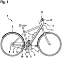
- the electric bicycle 1 comprises a crank drive 2 and an electric drive 3, which is arranged in the area of the crank drive 2.
- the electric bicycle 1 also comprises a chain 5 and a plurality of pinions 6 on a rear wheel 9.
- the reference numeral 4 denotes a power supply device.
- Cranks of the crank drive 2 are denoted by the reference numerals 7 and 8.
- the electric drive 3 is supplied with power from the power supply device 4.
- the power supply device 4 also supplies the control unit 10 with electrical energy.
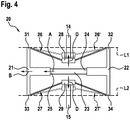
- the Figures 2 and 3 show the length change element 20 according to the invention. As in particular from FIG Figure 3 As can be seen, the length change element 20 has a trapezoidal shape in a side view.
- the length change element 20 comprises a first end region 21 and a second end region 22, between which a piezo actuator 23 is arranged.
- the piezo actuator 23 comprises an actuator base 24 and an actuator head 25.
- a first connecting arm 26 connects the first end area 21 to the second end area 22.
- a second connecting arm 27 also connects the first end area 21 to the second end area 22.
- the connecting arms are provided in such a way that in side view when the length change element 20 is in rest position, a symmetrical trapezoidal shape is obtained.
- a first connection area 28 for fixing the first cable area 14 on the length change element 20 is arranged on the first connecting arm 26.
- the second connecting arm 27 has a second connection area 29 for fixing the second cable area 15 on the length change element 20.
- the length change element 20 is thus arranged between two cable areas 14, 15 of the cable of a brake system 11 of the electric bicycle.
- the brake system 11 further comprises a speed sensor 12 which is arranged on the rear wheel 9.
- a brake lever 13 is provided on the handlebar in a known manner in order to actuate the rear wheel brake 16.
- a speed sensor is preferably also provided on the front wheel and a brake lever for a front wheel brake.
- the length change element 20 is integrated into the electric drive 3.
- the length change element 20 is supplied with power by the power supply device 4 of the electric bicycle.
- the change in length of the length change element 20 takes place in such a way that when the piezo actuator 23 is activated, the actuator head 25 is elongated in the direction of arrow A.
- the extension of the piezo actuator 23 also results in an extension of the length change element 20 in the direction of the arrow B, as in FIG Figure 3 drawn.
- the length change element 20 comes from the in Figure 3 in the starting position drawn in crossed lines to the in Figure 3 shown, shown in dashed lines, shortened position.
- a position of the first connecting arm 26 is denoted by the reference numeral 26 'and a position of the second connecting arm 27 is denoted by the reference numeral 27'.
- the two connecting arms 26, 27 therefore move due to an extension of the piezo actuator 23 in the direction of the piezo actuator 23, which is indicated by the arrows C.
- first connecting arm 26 and the second connecting arm 27 are on a first side of a line L1, which connects the first articulation point 31 to the second articulation point 32, and a line L2, which connects the third articulation point 33 to the fourth articulation point 34 , arranged on a side facing away from the piezo actuator 23.
- a shortening of the length change element 20 thus also means a tightening of the second cable area 15 in the direction of the first cable area 14, so that a braking force on the rear wheel brake 16 is reduced when the brake is released by pulling.
- the length change element 20 can be used in conjunction with an anti-lock braking system.
- the control unit 10 is set up in such a way that when a wheel blockage on the rear wheel 9 is detected by means of the sensor 12, which is, for example, a speed sensor, the control unit 10 actuates the piezo actuator 23 so that the length change element 20 is shortened.
- the braking force on the rear wheel brake 16 is reduced, so that a blockage of the rear wheel 9 is ended.
- a control loop can now be activated, since the sensor 12 on the rear wheel 9 now detects a rotation of the rear wheel 9 again.
- the control unit 10 can deactivate the piezo actuator 23 again, so that an extension of the cable pull occurs again, since the length change element 20 due to its inherent elasticity back into its in Figure 2 shown starting position returns.
- An anti-lock braking system for an electric bicycle 1 can thus be implemented by means of an inexpensive length change element 20 in a cable pull.
- the length change element 20 is very compact and can preferably be integrated into the electric drive 3. It is thus possible for electric bicycles to be mass-fitted with anti-lock braking systems in a cost-effective and compact manner.
- Figure 4 shows a length change element 20 according to a second embodiment of the invention.
- the length change element 20 is lengthened. This is achieved in that the first connecting arm 26 and the second connecting arm 27 are arranged on a second side of the lines L1 and L2 connecting the articulation points.
- the cable pull is also lengthened, since the first and second connection areas 28, 29, as in FIG Figure 4 indicated by the arrows D, are moved in the direction away from the piezo actuator 23.
- An extension of the cable pull can thus also be implemented in a simple manner.
- the deflected position of the length change element 20 is again shown in dashed lines.
- the inventive use of the connecting arms 26, 27 thus also results in a translation of the stroke of the piezo actuator 23 of a few millimeters, as can be seen from the Figures 3 and 4th can be seen.
- an extension of the piezo actuator 23 when it is activated is approximately 35 to 60 ⁇ m. Since the piezo actuator 23 has only a very small electrical power consumption, a range of an electric bicycle in particular is not significantly reduced. Furthermore, a very exact and rapid change in length of the length change element 20 can be carried out by means of the piezo actuator 23, so that the control unit 10 can implement a very good ABS regulation.
Landscapes
- Engineering & Computer Science (AREA)
- Transportation (AREA)
- Mechanical Engineering (AREA)
- Regulating Braking Force (AREA)
Claims (14)
- Câble Bowden pour un système de freinage d'un véhicule, en particulier d'un vélo électrique, comportant une première région de câble (14) et un élément de modification de longueur (20), lequel est disposé au niveau de la première région de câble (14), l'élément de modification de longueur (20) comportant- un actionneur piézoélectrique (23) doté d'un pied d'actionneur (24) et d'une tête d'actionneur (25),- une première région d'extrémité (21) et une deuxième région d'extrémité (22),- la première région d'extrémité (21) étant reliée à la tête d'actionneur (25) et la deuxième région d'extrémité (22) étant reliée au pied d'actionneur (24), et- au moins un premier bras de liaison (26), lequel relie la première région d'extrémité (21) à la deuxième région d'extrémité (22).
- Câble Bowden selon la revendication 1, caractérisé en ce que le premier bras de liaison (26) comprend une première région de raccordement (28) pour la fixation d'un objet.
- Câble Bowden selon la revendication 2, caractérisé en ce que la première région de raccordement (28) est disposée au centre du premier bras de liaison (26).
- Câble Bowden selon l'une des revendications 2 et 3, caractérisé en ce que le premier bras de liaison (26) est fixé à la première région d'extrémité (21) en un premier point d'articulation (31) et est fixé à la deuxième région d'extrémité (22) en un deuxième point d'articulation (32) et la première région de raccordement (28) est disposée sur un premier côté d'une ligne (L1) reliant le premier et le deuxième point d'articulation et l'actionneur piézoélectrique (23) est disposé sur un deuxième côté, opposé au premier côté, de la première ligne (L1).
- Câble Bowden selon la revendication 4, caractérisé en ce que la première région de raccordement (28) et l'actionneur piézoélectrique (23) sont tous deux disposés sur le deuxième côté de la ligne (L1).
- Câble Bowden selon l'une des revendications précédentes, caractérisé en ce que l'actionneur piézoélectrique (23) effectue une modification de longueur exclusivement au niveau de la tête d'actionneur (25) .
- Câble Bowden selon l'une des revendications précédentes, caractérisé en ce que le premier bras de liaison (26) est fabriqué à partir d'un matériau présentant une élasticité propre, en particulier à partir d'acier à ressorts ou de matière synthétique, et revient de manière autonome à la position initiale après qu'une déviation par l'actionneur piézoélectrique (23) à partir d'une position initiale a été effectuée.
- Câble Bowden selon l'une des revendications précédentes, caractérisé par un deuxième bras de liaison (27), lequel relie la première région d'extrémité (21) à la deuxième région d'extrémité (22) et lequel est fixé à la première région d'extrémité (21) en un troisième point d'articulation (33) et est fixé à la deuxième région d'extrémité (22) en un quatrième point d'articulation (34) .
- Câble Bowden selon la revendication 1, comportant en outre une deuxième région de câble (15), l'élément de modification de longueur (20) étant disposé entre la première région de câble (14) et la deuxième région de câble (15).
- Véhicule pouvant être entraîné par une force musculaire et par une force de moteur, en particulier vélo électrique, comportant un entraînement électrique (3), un dispositif d'alimentation en courant (4) et un câble Bowden selon l'une des revendications 1 à 9.
- Véhicule selon la revendication 12, caractérisé en ce que l'élément de modification de longueur (20) est disposé au niveau de l'entraînement électrique (3) ou est intégré dans l'entraînement électrique (3).
- Véhicule selon la revendication 10 ou 11, caractérisé en ce que l'actionneur piézoélectrique (23) de l'élément de modification de longueur (20) est relié au dispositif d'alimentation en courant (4).
- Véhicule selon l'une des revendications 10 à 12, comportant en outre une unité de commande (10) et un capteur (12) servant à la détection d'une vitesse de rotation d'une roue du véhicule, l'unité de commande (10) étant conçue pour activer l'actionneur piézoélectrique (23) en cas d'opération de freinage du véhicule et de blocage simultané de la roue, afin de provoquer une modification de longueur de l'élément de modification de longueur (20), de sorte que le blocage de la roue soit supprimé.
- Véhicule selon la revendication 13, caractérisé en ce qu'un capteur (12) servant à la détection de la vitesse de rotation est disposé au niveau d'une roue arrière et/ou d'une roue avant du véhicule.
Applications Claiming Priority (1)
| Application Number | Priority Date | Filing Date | Title |
|---|---|---|---|
| DE102015206475.1A DE102015206475A1 (de) | 2015-04-10 | 2015-04-10 | Längenänderungselement mit Piezoaktor und Fahrzeug mit ABS-Bremssystem |
Publications (2)
| Publication Number | Publication Date |
|---|---|
| EP3078557A1 EP3078557A1 (fr) | 2016-10-12 |
| EP3078557B1 true EP3078557B1 (fr) | 2021-08-11 |
Family
ID=55521387
Family Applications (1)
| Application Number | Title | Priority Date | Filing Date |
|---|---|---|---|
| EP16154960.5A Active EP3078557B1 (fr) | 2015-04-10 | 2016-02-10 | Élement de modification de longueur comprenant un piezoacteur et vehicule doté d'un système de freinage abs |
Country Status (2)
| Country | Link |
|---|---|
| EP (1) | EP3078557B1 (fr) |
| DE (1) | DE102015206475A1 (fr) |
Families Citing this family (2)
| Publication number | Priority date | Publication date | Assignee | Title |
|---|---|---|---|---|
| IT201800004690A1 (it) * | 2018-04-25 | 2019-10-25 | Dispositivo per la regolazione della forza frenante in impianti di frenatura a filo od idraulici | |
| DE102018114309B4 (de) * | 2018-06-14 | 2021-07-22 | Physik Instrumente (Pi) Gmbh & Co. Kg | Bremsvorrichtung sowie Antriebseinheit und Positioniervorrichtung |
Citations (2)
| Publication number | Priority date | Publication date | Assignee | Title |
|---|---|---|---|---|
| US4952835A (en) * | 1988-12-27 | 1990-08-28 | Ford Aerospace Corporation | Double saggital push stroke amplifier |
| WO2001076940A1 (fr) * | 2000-04-07 | 2001-10-18 | Eads Deutschland Gmbh | Dispositif d'actionnement piezo-electrique servant a commander les volets au niveau d'une ailette de rotor d'un helicoptere |
Family Cites Families (2)
| Publication number | Priority date | Publication date | Assignee | Title |
|---|---|---|---|---|
| DE102012222048A1 (de) | 2012-12-03 | 2014-06-05 | Robert Bosch Gmbh | Mechanisches Bremssystem für Zweiräder |
| DE102013213413A1 (de) * | 2013-07-09 | 2015-01-15 | Robert Bosch Gmbh | Aktuatorvorrichtung für eine Bremse eines Fahrzeugs, Fahrzeug sowie Verfahren zum Aktuieren einer Bremse eines Fahrzeugs |
-
2015
- 2015-04-10 DE DE102015206475.1A patent/DE102015206475A1/de not_active Withdrawn
-
2016
- 2016-02-10 EP EP16154960.5A patent/EP3078557B1/fr active Active
Patent Citations (2)
| Publication number | Priority date | Publication date | Assignee | Title |
|---|---|---|---|---|
| US4952835A (en) * | 1988-12-27 | 1990-08-28 | Ford Aerospace Corporation | Double saggital push stroke amplifier |
| WO2001076940A1 (fr) * | 2000-04-07 | 2001-10-18 | Eads Deutschland Gmbh | Dispositif d'actionnement piezo-electrique servant a commander les volets au niveau d'une ailette de rotor d'un helicoptere |
Also Published As
| Publication number | Publication date |
|---|---|
| EP3078557A1 (fr) | 2016-10-12 |
| DE102015206475A1 (de) | 2016-10-13 |
Similar Documents
| Publication | Publication Date | Title |
|---|---|---|
| DE102014009517B3 (de) | Lenksystem | |
| EP3395660B1 (fr) | Dispositif et procédé de réglage d'un angle de direction d'un guidon de deux-roues | |
| EP3676164B1 (fr) | Élément cylindrique creux et partie avant pour bicyclette, et bicyclette | |
| EP3078557B1 (fr) | Élement de modification de longueur comprenant un piezoacteur et vehicule doté d'un système de freinage abs | |
| EP3472023B1 (fr) | Colonne de direction pour véhicule à moteur | |
| EP3042837A1 (fr) | Guidon, en particulier pour un deux roues, avec poignée munie d'un capteur | |
| EP3795436A1 (fr) | Modulateur de pression pour un système antiblocage d'un vélo | |
| EP2205475B1 (fr) | Ensemble colonne de direction pour véhicules automobiles | |
| DE10056526C2 (de) | Sicherheitseinrichtung für die Lagerung eines Bremspedals in einem Kraftfahrzeug | |
| DE102005042281A1 (de) | Fußhebelwerkanordnung für ein Kraftfahrzeug | |
| DE102008000936A1 (de) | Radaufhängung für ein Fahrzeug und Verbindungselement für eine solche Radaufhängung | |
| DE102007035751A1 (de) | Vorrichtung und Verfahren zum Eingreifen in ein Lenksystem mit einer Aktivlenkeinrichtung | |
| DE3801109C1 (en) | Safety device | |
| WO2009000620A1 (fr) | Procédé pour ajuster un système de direction dans un véhicule | |
| EP2100780B1 (fr) | Système de protection contre les tonneaux avec un arceau extensible | |
| EP1272377A1 (fr) | Ensemble pedale atraumatique | |
| EP2611672B1 (fr) | Système de fixation d'une colonne de direction sur une pièce solidaire de la carrosserie d'un véhicule | |
| EP3092164B1 (fr) | Système de sécurité en matière composite renforcée par des fibres servant à absorber l'énergie en cas de collision | |
| DE102017121169B4 (de) | Bremsassistenzsystem für ein Zweirad | |
| DE102014014908A1 (de) | Vorrichtung zum zumindest teilweisen Lösen einer Befestigung zumindest eines Pedals in einem Fahrzeug bei einer Kollision | |
| DE102006013085B3 (de) | Lenksäulenbaueinheit | |
| EP2536597B1 (fr) | Systeme de direction pour vehicule | |
| EP3702257B1 (fr) | Véhicule doté d'un élément de commande permettant d'accélérer et de freiner | |
| DE102007031009A1 (de) | Pedalwerk für ein Fahrzeug, insbesondere ein Brems- oder Kupplungspedalwerk für ein Kraftfahrzeug, eine Lagerachse für ein Pedal, sowie ein Verfahren zur Montage des Pedalwerks und der Lagerachse | |
| DE102004041433A1 (de) | Crashgesicherte Lenkeinrichtung eines Fahrzeuges |
Legal Events
| Date | Code | Title | Description |
|---|---|---|---|
| PUAI | Public reference made under article 153(3) epc to a published international application that has entered the european phase |
Free format text: ORIGINAL CODE: 0009012 |
|
| AK | Designated contracting states |
Kind code of ref document: A1 Designated state(s): AL AT BE BG CH CY CZ DE DK EE ES FI FR GB GR HR HU IE IS IT LI LT LU LV MC MK MT NL NO PL PT RO RS SE SI SK SM TR |
|
| AX | Request for extension of the european patent |
Extension state: BA ME |
|
| STAA | Information on the status of an ep patent application or granted ep patent |
Free format text: STATUS: REQUEST FOR EXAMINATION WAS MADE |
|
| 17P | Request for examination filed |
Effective date: 20170412 |
|
| RBV | Designated contracting states (corrected) |
Designated state(s): AL AT BE BG CH CY CZ DE DK EE ES FI FR GB GR HR HU IE IS IT LI LT LU LV MC MK MT NL NO PL PT RO RS SE SI SK SM TR |
|
| RAP1 | Party data changed (applicant data changed or rights of an application transferred) |
Owner name: ROBERT BOSCH GMBH |
|
| STAA | Information on the status of an ep patent application or granted ep patent |
Free format text: STATUS: EXAMINATION IS IN PROGRESS |
|
| RIC1 | Information provided on ipc code assigned before grant |
Ipc: B60T 11/04 20060101AFI20200911BHEP Ipc: B60T 13/74 20060101ALI20200911BHEP Ipc: B60T 8/17 20060101ALI20200911BHEP |
|
| 17Q | First examination report despatched |
Effective date: 20200923 |
|
| GRAP | Despatch of communication of intention to grant a patent |
Free format text: ORIGINAL CODE: EPIDOSNIGR1 |
|
| STAA | Information on the status of an ep patent application or granted ep patent |
Free format text: STATUS: GRANT OF PATENT IS INTENDED |
|
| INTG | Intention to grant announced |
Effective date: 20210421 |
|
| GRAS | Grant fee paid |
Free format text: ORIGINAL CODE: EPIDOSNIGR3 |
|
| GRAA | (expected) grant |
Free format text: ORIGINAL CODE: 0009210 |
|
| STAA | Information on the status of an ep patent application or granted ep patent |
Free format text: STATUS: THE PATENT HAS BEEN GRANTED |
|
| AK | Designated contracting states |
Kind code of ref document: B1 Designated state(s): AL AT BE BG CH CY CZ DE DK EE ES FI FR GB GR HR HU IE IS IT LI LT LU LV MC MK MT NL NO PL PT RO RS SE SI SK SM TR |
|
| REG | Reference to a national code |
Ref country code: CH Ref legal event code: EP |
|
| REG | Reference to a national code |
Ref country code: DE Ref legal event code: R096 Ref document number: 502016013574 Country of ref document: DE |
|
| REG | Reference to a national code |
Ref country code: IE Ref legal event code: FG4D Free format text: LANGUAGE OF EP DOCUMENT: GERMAN Ref country code: AT Ref legal event code: REF Ref document number: 1419100 Country of ref document: AT Kind code of ref document: T Effective date: 20210915 |
|
| REG | Reference to a national code |
Ref country code: LT Ref legal event code: MG9D |
|
| REG | Reference to a national code |
Ref country code: NL Ref legal event code: MP Effective date: 20210811 |
|
| PG25 | Lapsed in a contracting state [announced via postgrant information from national office to epo] |
Ref country code: HR Free format text: LAPSE BECAUSE OF FAILURE TO SUBMIT A TRANSLATION OF THE DESCRIPTION OR TO PAY THE FEE WITHIN THE PRESCRIBED TIME-LIMIT Effective date: 20210811 Ref country code: SE Free format text: LAPSE BECAUSE OF FAILURE TO SUBMIT A TRANSLATION OF THE DESCRIPTION OR TO PAY THE FEE WITHIN THE PRESCRIBED TIME-LIMIT Effective date: 20210811 Ref country code: RS Free format text: LAPSE BECAUSE OF FAILURE TO SUBMIT A TRANSLATION OF THE DESCRIPTION OR TO PAY THE FEE WITHIN THE PRESCRIBED TIME-LIMIT Effective date: 20210811 Ref country code: LT Free format text: LAPSE BECAUSE OF FAILURE TO SUBMIT A TRANSLATION OF THE DESCRIPTION OR TO PAY THE FEE WITHIN THE PRESCRIBED TIME-LIMIT Effective date: 20210811 Ref country code: BG Free format text: LAPSE BECAUSE OF FAILURE TO SUBMIT A TRANSLATION OF THE DESCRIPTION OR TO PAY THE FEE WITHIN THE PRESCRIBED TIME-LIMIT Effective date: 20211111 Ref country code: NO Free format text: LAPSE BECAUSE OF FAILURE TO SUBMIT A TRANSLATION OF THE DESCRIPTION OR TO PAY THE FEE WITHIN THE PRESCRIBED TIME-LIMIT Effective date: 20211111 Ref country code: PT Free format text: LAPSE BECAUSE OF FAILURE TO SUBMIT A TRANSLATION OF THE DESCRIPTION OR TO PAY THE FEE WITHIN THE PRESCRIBED TIME-LIMIT Effective date: 20211213 Ref country code: FI Free format text: LAPSE BECAUSE OF FAILURE TO SUBMIT A TRANSLATION OF THE DESCRIPTION OR TO PAY THE FEE WITHIN THE PRESCRIBED TIME-LIMIT Effective date: 20210811 Ref country code: ES Free format text: LAPSE BECAUSE OF FAILURE TO SUBMIT A TRANSLATION OF THE DESCRIPTION OR TO PAY THE FEE WITHIN THE PRESCRIBED TIME-LIMIT Effective date: 20210811 |
|
| PG25 | Lapsed in a contracting state [announced via postgrant information from national office to epo] |
Ref country code: PL Free format text: LAPSE BECAUSE OF FAILURE TO SUBMIT A TRANSLATION OF THE DESCRIPTION OR TO PAY THE FEE WITHIN THE PRESCRIBED TIME-LIMIT Effective date: 20210811 Ref country code: LV Free format text: LAPSE BECAUSE OF FAILURE TO SUBMIT A TRANSLATION OF THE DESCRIPTION OR TO PAY THE FEE WITHIN THE PRESCRIBED TIME-LIMIT Effective date: 20210811 Ref country code: GR Free format text: LAPSE BECAUSE OF FAILURE TO SUBMIT A TRANSLATION OF THE DESCRIPTION OR TO PAY THE FEE WITHIN THE PRESCRIBED TIME-LIMIT Effective date: 20211112 |
|
| PG25 | Lapsed in a contracting state [announced via postgrant information from national office to epo] |
Ref country code: NL Free format text: LAPSE BECAUSE OF FAILURE TO SUBMIT A TRANSLATION OF THE DESCRIPTION OR TO PAY THE FEE WITHIN THE PRESCRIBED TIME-LIMIT Effective date: 20210811 |
|
| PG25 | Lapsed in a contracting state [announced via postgrant information from national office to epo] |
Ref country code: DK Free format text: LAPSE BECAUSE OF FAILURE TO SUBMIT A TRANSLATION OF THE DESCRIPTION OR TO PAY THE FEE WITHIN THE PRESCRIBED TIME-LIMIT Effective date: 20210811 |
|
| REG | Reference to a national code |
Ref country code: DE Ref legal event code: R097 Ref document number: 502016013574 Country of ref document: DE |
|
| PG25 | Lapsed in a contracting state [announced via postgrant information from national office to epo] |
Ref country code: SM Free format text: LAPSE BECAUSE OF FAILURE TO SUBMIT A TRANSLATION OF THE DESCRIPTION OR TO PAY THE FEE WITHIN THE PRESCRIBED TIME-LIMIT Effective date: 20210811 Ref country code: SK Free format text: LAPSE BECAUSE OF FAILURE TO SUBMIT A TRANSLATION OF THE DESCRIPTION OR TO PAY THE FEE WITHIN THE PRESCRIBED TIME-LIMIT Effective date: 20210811 Ref country code: RO Free format text: LAPSE BECAUSE OF FAILURE TO SUBMIT A TRANSLATION OF THE DESCRIPTION OR TO PAY THE FEE WITHIN THE PRESCRIBED TIME-LIMIT Effective date: 20210811 Ref country code: EE Free format text: LAPSE BECAUSE OF FAILURE TO SUBMIT A TRANSLATION OF THE DESCRIPTION OR TO PAY THE FEE WITHIN THE PRESCRIBED TIME-LIMIT Effective date: 20210811 Ref country code: CZ Free format text: LAPSE BECAUSE OF FAILURE TO SUBMIT A TRANSLATION OF THE DESCRIPTION OR TO PAY THE FEE WITHIN THE PRESCRIBED TIME-LIMIT Effective date: 20210811 Ref country code: AL Free format text: LAPSE BECAUSE OF FAILURE TO SUBMIT A TRANSLATION OF THE DESCRIPTION OR TO PAY THE FEE WITHIN THE PRESCRIBED TIME-LIMIT Effective date: 20210811 |
|
| PLBE | No opposition filed within time limit |
Free format text: ORIGINAL CODE: 0009261 |
|
| STAA | Information on the status of an ep patent application or granted ep patent |
Free format text: STATUS: NO OPPOSITION FILED WITHIN TIME LIMIT |
|
| 26N | No opposition filed |
Effective date: 20220512 |
|
| PG25 | Lapsed in a contracting state [announced via postgrant information from national office to epo] |
Ref country code: IT Free format text: LAPSE BECAUSE OF FAILURE TO SUBMIT A TRANSLATION OF THE DESCRIPTION OR TO PAY THE FEE WITHIN THE PRESCRIBED TIME-LIMIT Effective date: 20210811 |
|
| PG25 | Lapsed in a contracting state [announced via postgrant information from national office to epo] |
Ref country code: SI Free format text: LAPSE BECAUSE OF FAILURE TO SUBMIT A TRANSLATION OF THE DESCRIPTION OR TO PAY THE FEE WITHIN THE PRESCRIBED TIME-LIMIT Effective date: 20210811 |
|
| PG25 | Lapsed in a contracting state [announced via postgrant information from national office to epo] |
Ref country code: MC Free format text: LAPSE BECAUSE OF FAILURE TO SUBMIT A TRANSLATION OF THE DESCRIPTION OR TO PAY THE FEE WITHIN THE PRESCRIBED TIME-LIMIT Effective date: 20210811 |
|
| REG | Reference to a national code |
Ref country code: CH Ref legal event code: PL |
|
| REG | Reference to a national code |
Ref country code: BE Ref legal event code: MM Effective date: 20220228 |
|
| GBPC | Gb: european patent ceased through non-payment of renewal fee |
Effective date: 20220210 |
|
| PG25 | Lapsed in a contracting state [announced via postgrant information from national office to epo] |
Ref country code: LU Free format text: LAPSE BECAUSE OF NON-PAYMENT OF DUE FEES Effective date: 20220210 |
|
| PG25 | Lapsed in a contracting state [announced via postgrant information from national office to epo] |
Ref country code: FR Free format text: LAPSE BECAUSE OF NON-PAYMENT OF DUE FEES Effective date: 20220228 |
|
| PG25 | Lapsed in a contracting state [announced via postgrant information from national office to epo] |
Ref country code: LI Free format text: LAPSE BECAUSE OF NON-PAYMENT OF DUE FEES Effective date: 20220228 Ref country code: IE Free format text: LAPSE BECAUSE OF NON-PAYMENT OF DUE FEES Effective date: 20220210 Ref country code: GB Free format text: LAPSE BECAUSE OF NON-PAYMENT OF DUE FEES Effective date: 20220210 Ref country code: CH Free format text: LAPSE BECAUSE OF NON-PAYMENT OF DUE FEES Effective date: 20220228 |
|
| PG25 | Lapsed in a contracting state [announced via postgrant information from national office to epo] |
Ref country code: BE Free format text: LAPSE BECAUSE OF NON-PAYMENT OF DUE FEES Effective date: 20220228 |
|
| REG | Reference to a national code |
Ref country code: AT Ref legal event code: MM01 Ref document number: 1419100 Country of ref document: AT Kind code of ref document: T Effective date: 20220210 |
|
| PG25 | Lapsed in a contracting state [announced via postgrant information from national office to epo] |
Ref country code: AT Free format text: LAPSE BECAUSE OF NON-PAYMENT OF DUE FEES Effective date: 20220210 |
|
| PGFP | Annual fee paid to national office [announced via postgrant information from national office to epo] |
Ref country code: DE Payment date: 20230426 Year of fee payment: 8 |
|
| PG25 | Lapsed in a contracting state [announced via postgrant information from national office to epo] |
Ref country code: HU Free format text: LAPSE BECAUSE OF FAILURE TO SUBMIT A TRANSLATION OF THE DESCRIPTION OR TO PAY THE FEE WITHIN THE PRESCRIBED TIME-LIMIT; INVALID AB INITIO Effective date: 20160210 |
|
| PG25 | Lapsed in a contracting state [announced via postgrant information from national office to epo] |
Ref country code: MK Free format text: LAPSE BECAUSE OF FAILURE TO SUBMIT A TRANSLATION OF THE DESCRIPTION OR TO PAY THE FEE WITHIN THE PRESCRIBED TIME-LIMIT Effective date: 20210811 Ref country code: CY Free format text: LAPSE BECAUSE OF FAILURE TO SUBMIT A TRANSLATION OF THE DESCRIPTION OR TO PAY THE FEE WITHIN THE PRESCRIBED TIME-LIMIT Effective date: 20210811 |
|
| PG25 | Lapsed in a contracting state [announced via postgrant information from national office to epo] |
Ref country code: TR Free format text: LAPSE BECAUSE OF FAILURE TO SUBMIT A TRANSLATION OF THE DESCRIPTION OR TO PAY THE FEE WITHIN THE PRESCRIBED TIME-LIMIT Effective date: 20210811 |
|
| REG | Reference to a national code |
Ref country code: DE Ref legal event code: R119 Ref document number: 502016013574 Country of ref document: DE |
|
| PG25 | Lapsed in a contracting state [announced via postgrant information from national office to epo] |
Ref country code: MT Free format text: LAPSE BECAUSE OF FAILURE TO SUBMIT A TRANSLATION OF THE DESCRIPTION OR TO PAY THE FEE WITHIN THE PRESCRIBED TIME-LIMIT Effective date: 20210811 |
|
| PG25 | Lapsed in a contracting state [announced via postgrant information from national office to epo] |
Ref country code: DE Free format text: LAPSE BECAUSE OF NON-PAYMENT OF DUE FEES Effective date: 20240903 |
|
| PG25 | Lapsed in a contracting state [announced via postgrant information from national office to epo] |
Ref country code: DE Free format text: LAPSE BECAUSE OF NON-PAYMENT OF DUE FEES Effective date: 20240903 |