EP3078562A1 - Erfassungssystem des eintritts in eine kurve einer karosseriestruktur eines schienenfahrzeugs - Google Patents
Erfassungssystem des eintritts in eine kurve einer karosseriestruktur eines schienenfahrzeugs Download PDFInfo
- Publication number
- EP3078562A1 EP3078562A1 EP16163131.2A EP16163131A EP3078562A1 EP 3078562 A1 EP3078562 A1 EP 3078562A1 EP 16163131 A EP16163131 A EP 16163131A EP 3078562 A1 EP3078562 A1 EP 3078562A1
- Authority
- EP
- European Patent Office
- Prior art keywords
- sensor
- body structure
- axle box
- sensors
- axle
- Prior art date
- Legal status (The legal status is an assumption and is not a legal conclusion. Google has not performed a legal analysis and makes no representation as to the accuracy of the status listed.)
- Withdrawn
Links
- 238000001514 detection method Methods 0.000 claims abstract description 23
- 230000004087 circulation Effects 0.000 claims abstract description 8
- 238000004891 communication Methods 0.000 claims abstract description 3
- 230000006854 communication Effects 0.000 claims abstract description 3
- 230000006835 compression Effects 0.000 claims description 14
- 238000007906 compression Methods 0.000 claims description 14
- 238000013519 translation Methods 0.000 claims description 7
- 238000006073 displacement reaction Methods 0.000 claims description 5
- 235000021183 entrée Nutrition 0.000 description 4
- 239000000463 material Substances 0.000 description 4
- 230000003405 preventing effect Effects 0.000 description 4
- 230000033001 locomotion Effects 0.000 description 2
- 238000005461 lubrication Methods 0.000 description 2
- 230000002441 reversible effect Effects 0.000 description 2
- 239000011324 bead Substances 0.000 description 1
- 230000000694 effects Effects 0.000 description 1
- 238000002955 isolation Methods 0.000 description 1
- 230000001050 lubricating effect Effects 0.000 description 1
- 230000005291 magnetic effect Effects 0.000 description 1
- 230000007704 transition Effects 0.000 description 1
Images

Classifications
-
- B—PERFORMING OPERATIONS; TRANSPORTING
- B61—RAILWAYS
- B61F—RAIL VEHICLE SUSPENSIONS, e.g. UNDERFRAMES, BOGIES OR ARRANGEMENTS OF WHEEL AXLES; RAIL VEHICLES FOR USE ON TRACKS OF DIFFERENT WIDTH; PREVENTING DERAILING OF RAIL VEHICLES; WHEEL GUARDS, OBSTRUCTION REMOVERS OR THE LIKE FOR RAIL VEHICLES
- B61F5/00—Constructional details of bogies; Connections between bogies and vehicle underframes; Arrangements or devices for adjusting or allowing self-adjustment of wheel axles or bogies when rounding curves
- B61F5/26—Mounting or securing axle-boxes in vehicle or bogie underframes
- B61F5/30—Axle-boxes mounted for movement under spring control in vehicle or bogie underframes
- B61F5/301—Axle-boxes mounted for movement under spring control in vehicle or bogie underframes incorporating metal springs
- B61F5/302—Leaf springs
-
- B—PERFORMING OPERATIONS; TRANSPORTING
- B61—RAILWAYS
- B61K—AUXILIARY EQUIPMENT SPECIALLY ADAPTED FOR RAILWAYS, NOT OTHERWISE PROVIDED FOR
- B61K3/00—Wetting or lubricating rails or wheel flanges
- B61K3/02—Apparatus therefor combined with vehicles
Definitions
- the invention relates to a railway vehicle body structure equipped with at least one system for detecting the entry curve of said body structure.
- the pivoting of the axle, and therefore the associated curve taking is an information that is very important when, for example, it is desired to control an ancillary system only in the curves. This could be for example a wheel flange lubrication system. It is thus a question of detecting the taking of curve to feed an annexed system.
- the only existing mechanical system for detecting the entry curve of a railway material consists of a system of return rods in which a first rod is mounted on the axis of a bogie, and causes in pivoting a second bead itself driving a sheet in turn, the ends of which are capable of passing from a first inactive position in which one end is in magnetic contact with a magnet secured to the body structure, to a second active position in the end in question is no longer in contact with the magnet, which results in the bogie pivoted relative to the body structure and the rail vehicle is curved.
- the present invention aims at a rail vehicle body structure equipped with at least one system for detecting the entry into curve of said body structure, said detection system being at the same time simple, not bulky and adaptable to a body structure not equipped with bogies.
- the curved entry detection system of a railway vehicle body structure of the invention uses the relative movement between the body structure of a railway vehicle and the axle boxes.
- the detection system provides at least one mechanical sensor integral with the body structure, which adopts an idle free position with respect to the axle box when the body structure travels in a straight line, and an active contact position on the axle box when the body structure enters and circulates.
- the transition from the inactive position to the active position of the sensor is effected by a longitudinal stroke of the axle box relative to the body structure when the latter is in curve, bearing on the sensor.
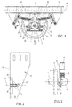
- axles 9 which are, as illustrated on the figure 6 , consisting of an axis 1 at the end of which are two opposite wheels 2,2a each having a non-visible bearing which is housed in an associated axle box 3,4 allowing rotation of the axis relative to a fulcrum.
- the axle box 4 is connected to a leaf spring group 5 which is connected to the body structure 6 by two articulated double-ring systems 7, 8 giving the axle box 4 freedom in rotation relative to to the axis 1 of the axle 9 and a longitudinal freedom along the axis XX 'of advancement of the body structure 6 of 22.5 millimeters or even up to 26.5 millimeters after wear.
- the axle box 4 moves in particular longitudinally relative to the body structure 6 over a maximum distance of 26.5 millimeters from its reference position when the structure of the body cashier 6 is in a straight line.
- the detection system comprises at least one mechanical roller or push sensor 10, or digital sensor, extending along a main contact axis BB ', secured to the body structure 6 and located close and without contact in its position.
- the axle box 4 moves longitudinally along the axes XX 'and BB' until coming into contact with the contactor of the sensor 10. moving it to its active open position.
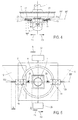
- the detection system comprises two sensors 10,11 located on either side of the axle box 4 in opposite direction and in main contact axis alignment BB 'which is parallel to or coincident with the longitudinal axis XX 'of displacement of the body structure 6.
- Each sensor 10, 11 is attached to a support 18 ( figure 2 ) mounted on a guard plate 12, 13 extending substantially parallel to the wheel 2 located nearby ( figure 3 ), whose upper end 14,15 is secured to the body structure 6 and the lower end 16,17 extends substantially below the axle box 4.
- the position of the sensors 10,11 on the plate of associated guard 12,13 is such that the sensors 10,11 are arranged opposite the axle box 4.
- each sensor 10, 11 is mounted on the support 18 which is flush with the edge 19 of the guard plate 13 located on the side of the axle box 4.
- the support 18 is mounted to move in translation along the main contact axis BB 10 of the sensor 10 not visible in this figure, by means of oblong slots 20 formed on the guard plate 13 and in which can be slid head retaining screws of the support 18 to the guard plate 13.
- a stop 21 is by elsewhere welded to the guard plate 13 near the end of the support 18 which is opposite the edge 19, the distance between this end of the support 18 and the stop 21 being greater than the length of the oblong slots 20, so that the support 18 does not come against the stop 21 before having finished its race in said oblong slots 20.
- each sensor 10, 11 is mounted on a double return spring 22, 23 which is integral with the corresponding stop 21, 21 a. It should also be noted that each sensor 10, 11 is of the spring-return sensor type and thus also intrinsically comprises a return spring 122, 123 ( figure 5 ). Due to the presence of the double external return springs 22, 23, the return springs 122, 123 are mounted inside said sensors 10, 11 or could be alternately mounted outside the sensors 10, 11 but on the side of the associated contactor 25,26.
- the flexibility of the external return springs 22, 23 is less than the flexibility of the internal return springs 122, 123 so that the support 18 slides in the oblong slots 20 towards and to the stop 21 only when the springs of internal booster 122,123 are in maximum compression.
- the sensor 10 is positioned on its associated guard plate 12 so as to respect a certain distance a between the box axle 4 and the head of the contactor 25 of the sensor 10.
- This distance a must be at least equal to the longitudinal stroke of the axle box 4 can operate in a straight line to prevent the sensor 10 does not is activated in the open position as long as the material is not curved.
- This longitudinal race in a straight line is, according to the wheelbase of the material, between 3.5 and 6 millimeters.
- the contactor 25 of the sensor 10 is located at a distance of 6 millimeters from the axle box 4.
- the return spring 122 of the sensor 10 is in the detent position, so that the sensor 10 remains in position. inactive closed.
- the longitudinal stroke of the axle box 4 becomes greater than 6 millimeters and the axle box 4 presses the contactor 25 of the sensor considered 10, which results in the compression of the spring of 122 and the drive in the active position of said sensor 10.
- the maximum stroke b of the sensor 10 which is generally 10 millimeters, the internal return spring 122 is compressed, while the double outer return spring 22 remains in the detent position due to its lower flexibility than the internal return spring 122 of the sensors 10.
- the double return spring 22 is compressed along its stroke c ( figure 4 ), the associated sensor 10,11 always being in the open active position. This configuration persists up to the maximum stroke of the axle box of 22.5 millimeters, or even 26.5 millimeters as mentioned before.
- the contact between the contactor 25 of the sensor 10 and the axle box 4 takes place from a longitudinal stroke of the axle box 4 of 6 millimeters. and up to a maximum longitudinal stroke of 22.5 millimeters or 26.5 millimeters.
- the stroke of the contactor 25 is thus split in two: part of its stroke is generated by the compression of the internal return spring 122 while the double return spring 22 is in expansion, and the other part by the compression of the double spring 22 while the internal return spring 122 is held in compression.
- This system thus makes it possible to increase the length of the intrinsic stroke of the sensor 10.
- the sensor 10 switches to the closed position when the longitudinal stroke of the axle box 4 becomes less than 6 millimeters.
- each sensor 10, 11 is connected to a pneumatic energy source 27 which may be either already available on the axle or produced by the axle, and to an additional system 28 which may be, as for the first mode of realization, a simple information system relaying the fact that the body structure 6 is curved, or a system using this information to drive a device that triggers when the body structure 6 is curved.
- this device may be a wheel flange lubrication system for lubricating the wheel-rail interface only when the body structure is curved.
- the pneumatic energy source 27 does not supply the auxiliary system 28.
- the axle box 4 moves longitudinally along the arrow F3 to come into contact support on the contactor 26 of the sensor 11 by moving the sensor 11 in the direction of the arrow F3, which results in the compression of the internal return spring 123 and the passage of the sensor 11 in the active open position, and which generates concomitantly the supply of the annex system 28 by the pneumatic energy source 27 via this sensor 11.
- the detection system can also take the form of a second variant in which it comprises two sensors 10a, 11a located on the same side of the two axle boxes 4,3 of the axle 9.
- the positioning of the sensors 10a, 11a on the brackets and associated guard plates is identical to that described with reference to the first variant.
- each sensor 10a, 11a is connected to a pneumatic energy source 27a and to an additional system 28a.
- the pneumatic energy source 27a does not supply the auxiliary system 28a.
- the contactor 25a is released from the contact support with the axle box 4, the internal return spring 122a returns to its position. by triggering the sensor 10a in the closed inactive position prohibiting the supply of the annex system 28a by the pneumatic energy source 27a.
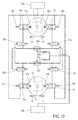
- the detection system of the second embodiment may also take the form of a third variant in which it comprises two first sensors 10b, 11b located on either side of a first axle box 4 of the first axle 9 of the body structure 6, and two second sensors 11c, 10c located on either side of a second axle box 4a of the second axle 9a located on the same side of the body structure 6 as the first box of axle 4.
- a first couple of sensors 10b, 10c which are more external with respect to the body structure 6 and a second pair of sensors 11b, 11c which are the most internal relative to the body structure 6.
- each sensor 10b, 10c, 11b, 11c is connected to a pneumatic power source 27b and to a control distributor 30a, 30b, 31a, 31b which is itself connected on the one hand to the control distributor 30b , 30a, 31b, 31a of the associated torque sensor 10c, 10b, 11c, 11b, and secondly connected to an OR function 32a, 32b.
- a first OR function 32a is common to the two control distributors 30a, 31a of the two sensors 10b, 11b located on the same first axle 9, and the second OR function 32b is common to the two control distributors 30b, 31b two sensors 10c, 11c located on the same second axle 9a.
- the first OR function 32a is connected to a first nonreturn valve 33a and the second OR function 32b is connected to a second nonreturn valve 33b, the two nonreturn valves 33a, 33b being connected to an annex system 28b.
- the first axle box 4 moves longitudinally along the arrow F7 to come into contacting contact on the contactor 36a of the sensor 11b by moving the switch 36a in the direction of the arrow F7, which results in compression the internal return spring 34a and the passage of the sensor 11b in the active open position, which concomitantly generates the passage of the pneumatic energy in the associated control valve 31a.
- This control distributor 31a then actuates closing the control valve 31b of the sensor 11c, preventing air from escaping through this sensor 11c and supplies the first OR function 32a which opens the first non-return valve 33a , closes the second check valve 33b and supplies the annex system 28b.
- the second sensor 11c With a delay time relative to the opening of the first sensor 11b, the second sensor 11c also opens by moving the second axle box 4a according to the arrow F7 until coming into contact support on the contactor 36b of the sensor 11c by moving this contactor 36b in the direction of the arrow F7,
- the control distributor 31b is kept in the closed position by the pneumatic energy sent by the control distributor 31a which was fed first .
- the second axle box 4a moves longitudinally along the arrow F7 to come into contact support on the contactor 36b of the sensor 11c by moving this sensor 11c in the direction of the arrow F7, which results in the compression of the internal return spring 34b and the passage of the sensor 11c in the active open position, which generates concomitantly the passage of the pneumatic energy in the associated control valve 31 b.
- This control distributor 31 b then actuates closing the control valve 31a of the sensor 11b by preventing air from escaping through this sensor 11b and supplies the second OR function 32b which opens the second non-return valve 33b, closes the first check valve 33a and feeds the annex system 28b.
- the second sensor 11b With a delay time relative to the opening of the first sensor 11c, the second sensor 11b also opens by moving the first axle box 4 according to the arrow F7 to come into contact support on the contactor 36a of the sensor 11b by moving the sensor 11b in the direction of the arrow F7.
- the control valve 31a is held in the closed position by the pneumatic energy sent by the control distributor 31b which has been fed first.
- the second axle box 4a moves longitudinally along the arrow F8 to come into contact support on the contactor 37b of the sensor 10c by moving the sensor 10c in the direction of the arrow F8, which results in the setting spring tension 35b and the passage of the sensor 10c in the active open position, which concomitantly generates the passage of the pneumatic energy in the associated control valve 30b.
- This control distributor 30b then actuates closing the control distributor 30a of the sensor 10b by preventing air from escaping by this sensor 10b and supplies the second OR function 32b which opens the second nonreturn valve 33b, closes the first check valve 33a and feeds the annex system 28b.
- the second sensor 10b With a time delay relative to the opening of the first sensor 10c, the second sensor 10b also opens by moving the first axle box 4 according to the arrow F8 to come into contact support on the contactor 37a of the sensor 10b by moving this sensor 10b in the direction of the arrow F8.
- the control distributor 30a is held in the closed position by the pneumatic energy sent by the control distributor 30b which has been fed first.
- the first axle box 4 moves longitudinally along the arrow F8 to come into contact support on the contactor 37a of the sensor 10b by moving the sensor 10b in the direction of the arrow F8, which results in the setting the tension of the spring 35a and the passage of the sensor 10b in the active open position, which concomitantly generates the passage of the pneumatic energy in the associated control distributor 30a.
- This control distributor 30a then actuates closing the control distributor 30b of the sensor 10c by preventing air from escaping by this sensor 10c and supplies the first OR function 32a which opens the first non-return valve 33a, closes the second non-return valve 33b and feeds the annex system 28b.
- the second sensor 10c With a delay time relative to the opening of the first sensor 10b, the second sensor 10c also opens by moving the second axle box 4a along the arrow F8 to come into contact support on the contactor 37b of the sensor 10c by moving this sensor 10c in the direction of the arrow F8.
- the control distributor 30b is held in the closed position by the pneumatic energy sent by the control distributor 30a which has been fed first.
Landscapes
- Engineering & Computer Science (AREA)
- Mechanical Engineering (AREA)
- Vehicle Body Suspensions (AREA)
Applications Claiming Priority (1)
| Application Number | Priority Date | Filing Date | Title |
|---|---|---|---|
| FR1500651A FR3034391B1 (fr) | 2015-04-01 | 2015-04-01 | Systeme de detection de l'entree en courbe d'une structure de caisse de vehicule ferroviaire |
Publications (1)
| Publication Number | Publication Date |
|---|---|
| EP3078562A1 true EP3078562A1 (de) | 2016-10-12 |
Family
ID=53514241
Family Applications (1)
| Application Number | Title | Priority Date | Filing Date |
|---|---|---|---|
| EP16163131.2A Withdrawn EP3078562A1 (de) | 2015-04-01 | 2016-03-31 | Erfassungssystem des eintritts in eine kurve einer karosseriestruktur eines schienenfahrzeugs |
Country Status (2)
| Country | Link |
|---|---|
| EP (1) | EP3078562A1 (de) |
| FR (1) | FR3034391B1 (de) |
Cited By (1)
| Publication number | Priority date | Publication date | Assignee | Title |
|---|---|---|---|---|
| EP4722070A1 (de) * | 2024-10-04 | 2026-04-08 | Greenbrier Poland sp. z o.o. | Verfahren zur befestigung der gabelführungen der radsatzlagergehäuse im fahrwerk von zweiachsigen güterwagen und ein satz anschläge im fahrwerk von zweiachsigen waggons |
Citations (5)
| Publication number | Priority date | Publication date | Assignee | Title |
|---|---|---|---|---|
| FR2474423A1 (fr) * | 1980-01-30 | 1981-07-31 | Schweizerische Lokomotiv | Dispositif de commande du mouvement de rotation d'un essieu monte de vehicule ferriviaire au passage dans une courbe |
| FR2594936A1 (fr) * | 1985-10-08 | 1987-08-28 | Madison Kipp Corp | Appareil de lubrification automatique |
| CA2014168C (fr) * | 1989-04-10 | 1994-07-19 | Michel Rimbaud | Essieu a suspension primaire et a orientation variable |
| JP2010111329A (ja) * | 2008-11-07 | 2010-05-20 | Kinki Sharyo Co Ltd | 鉄道車両の車載式の潤滑剤付与方法と装置 |
| US20140311378A1 (en) * | 2011-12-19 | 2014-10-23 | Nippon Steel & Sumitomo Metal Corporation | Railway vehicle steering truck |
-
2015
- 2015-04-01 FR FR1500651A patent/FR3034391B1/fr active Active
-
2016
- 2016-03-31 EP EP16163131.2A patent/EP3078562A1/de not_active Withdrawn
Patent Citations (5)
| Publication number | Priority date | Publication date | Assignee | Title |
|---|---|---|---|---|
| FR2474423A1 (fr) * | 1980-01-30 | 1981-07-31 | Schweizerische Lokomotiv | Dispositif de commande du mouvement de rotation d'un essieu monte de vehicule ferriviaire au passage dans une courbe |
| FR2594936A1 (fr) * | 1985-10-08 | 1987-08-28 | Madison Kipp Corp | Appareil de lubrification automatique |
| CA2014168C (fr) * | 1989-04-10 | 1994-07-19 | Michel Rimbaud | Essieu a suspension primaire et a orientation variable |
| JP2010111329A (ja) * | 2008-11-07 | 2010-05-20 | Kinki Sharyo Co Ltd | 鉄道車両の車載式の潤滑剤付与方法と装置 |
| US20140311378A1 (en) * | 2011-12-19 | 2014-10-23 | Nippon Steel & Sumitomo Metal Corporation | Railway vehicle steering truck |
Cited By (1)
| Publication number | Priority date | Publication date | Assignee | Title |
|---|---|---|---|---|
| EP4722070A1 (de) * | 2024-10-04 | 2026-04-08 | Greenbrier Poland sp. z o.o. | Verfahren zur befestigung der gabelführungen der radsatzlagergehäuse im fahrwerk von zweiachsigen güterwagen und ein satz anschläge im fahrwerk von zweiachsigen waggons |
Also Published As
| Publication number | Publication date |
|---|---|
| FR3034391B1 (fr) | 2017-03-17 |
| FR3034391A1 (fr) | 2016-10-07 |
Similar Documents
| Publication | Publication Date | Title |
|---|---|---|
| EP0724279B1 (de) | Fensterheber für Fahrzeuge mit Schwingarm und Zahnradsektor | |
| FR2883010A1 (fr) | Barriere de securite perfectionnee | |
| FR2957068A1 (fr) | Dispositif de calage a quai d'un vehicule de transport de marchandises et installation le comportant | |
| EP2193063B1 (de) | Schienengestell mit rädern zur ausrichtung entsprechend einer streckenkrümmung | |
| EP3078562A1 (de) | Erfassungssystem des eintritts in eine kurve einer karosseriestruktur eines schienenfahrzeugs | |
| EP3473513B1 (de) | Trittstufe für ein schienenfahrzeug, entsprechendes türsystem, schienenfahrzeug und verfahren | |
| FR2955295A1 (fr) | Cabriolet comprenant un agencement de toit | |
| EP1597101B1 (de) | Versenkbares dach für ein fahrzeug | |
| EP2734389B1 (de) | Amphibienfahrzeug | |
| BE494574A (fr) | Bicyclette reductible munie d'un micromoteur | |
| EP4558430A1 (de) | System zum manuellen festlegen eines fahrzeugs vor einem ladedock | |
| FR2881998A1 (fr) | Porte coulissante stable | |
| FR2885158A1 (fr) | Vehicule avec un hayon | |
| FR2938586A1 (fr) | Structure de porte coulissante pour vehicule, et vehicule equipe d'une telle structure | |
| EP3075624B1 (de) | Erfassungsvorrichtung einer kurve für ein schienenfahrzeug mit drehgestellen | |
| FR3124994A1 (fr) | Elément de garnissage comprenant une pièce mobile déplaçable automatiquement ou manuellement | |
| EP2529996B1 (de) | Blockiervorrichtung für ein Lenksystem eines Kraftfahrzeugs | |
| EP2152562B1 (de) | Bidirektionales führungssystem mit seitlicher schwingungsbegrenzung für eine durch eine schiene in der erde geführte strassenachse | |
| FR2807724A3 (fr) | Dispositif de serrage automatique pour systemes de transport a cables du type a deux cables | |
| EP1375046B1 (de) | Tragbare Punktschweisszange | |
| EP1445153B1 (de) | Fahrzeug mit einem einziehbaren Unterfahrschutzbalken | |
| FR2817803A1 (fr) | Toit retractable pour vehicule comprenant des elements de toit equipes de glissieres telescopiques | |
| FR3045529A1 (fr) | Marchepied escamotable pour vehicule automobile. | |
| WO2006131608A1 (fr) | Dispositif de deplacement de vehicules | |
| FR2800786A1 (fr) | Dispositif d'ouverture et de fermeture motorisee d'un vantail de portail ou analogue |
Legal Events
| Date | Code | Title | Description |
|---|---|---|---|
| PUAI | Public reference made under article 153(3) epc to a published international application that has entered the european phase |
Free format text: ORIGINAL CODE: 0009012 |
|
| AK | Designated contracting states |
Kind code of ref document: A1 Designated state(s): AL AT BE BG CH CY CZ DE DK EE ES FI FR GB GR HR HU IE IS IT LI LT LU LV MC MK MT NL NO PL PT RO RS SE SI SK SM TR |
|
| AX | Request for extension of the european patent |
Extension state: BA ME |
|
| STAA | Information on the status of an ep patent application or granted ep patent |
Free format text: STATUS: THE APPLICATION HAS BEEN PUBLISHED |
|
| STAA | Information on the status of an ep patent application or granted ep patent |
Free format text: STATUS: THE APPLICATION IS DEEMED TO BE WITHDRAWN |
|
| 18D | Application deemed to be withdrawn |
Effective date: 20170413 |