EP3078565A1 - Dispositif de commande, procédé de commande et programme de commande d'exploitation de trains - Google Patents
Dispositif de commande, procédé de commande et programme de commande d'exploitation de trains Download PDFInfo
- Publication number
- EP3078565A1 EP3078565A1 EP14868529.0A EP14868529A EP3078565A1 EP 3078565 A1 EP3078565 A1 EP 3078565A1 EP 14868529 A EP14868529 A EP 14868529A EP 3078565 A1 EP3078565 A1 EP 3078565A1
- Authority
- EP
- European Patent Office
- Prior art keywords
- train
- time
- concerned
- station
- running
- Prior art date
- Legal status (The legal status is an assumption and is not a legal conclusion. Google has not performed a legal analysis and makes no representation as to the accuracy of the status listed.)
- Withdrawn
Links
Images


Classifications
-
- B—PERFORMING OPERATIONS; TRANSPORTING
- B61—RAILWAYS
- B61L—GUIDING RAILWAY TRAFFIC; ENSURING THE SAFETY OF RAILWAY TRAFFIC
- B61L27/00—Central railway traffic control systems; Trackside control; Communication systems specially adapted therefor
- B61L27/10—Operations, e.g. scheduling or time tables
- B61L27/16—Trackside optimisation of vehicle or train operation
-
- B—PERFORMING OPERATIONS; TRANSPORTING
- B61—RAILWAYS
- B61L—GUIDING RAILWAY TRAFFIC; ENSURING THE SAFETY OF RAILWAY TRAFFIC
- B61L15/00—Indicators provided on the vehicle or train for signalling purposes
- B61L15/0058—On-board optimisation of vehicle or vehicle train operation
Definitions
- An embodiment of the present invention relates to a train operation control device, a control method, and a control program.
- Energy saving in terms of railways includes replacing auxiliary machines such as air-conditioners or lighting with energy-efficient machines or reducing energy consumption during train running. Particularly, in order to reduce energy consumption in train running, methods of curtailing the amount of energy necessary for power running and creating a situation with a good energy recovery efficiency to apply a regenerative brake have been proposed.
- trains result in running at a lower speed and the slower running to a next station directly leads to energy saving.
- Nonpatent Literature 1 " Numerical Study on Dynamic Programming Applied to Optimization of Running Profile of a Train", by Miyatake and Ko, The Institute of Electrical Engineers of Japan, 2004
- the operation as initially planned may be obstructed by an unexpected event such as an increased stop time due to a great number of passengers to board and alight or a bag stuck in doors.
- every train is operated to make up for the delay as much as possible.
- the prevent invention aims to provide a train operation control device, a control method, and a control program which can make up for a delay when it occurs and prevent an increase in unnecessary energy consumption to realize energy saving.
- a running profile generator of a train operation control device of an embodiment generates, when a train concerned arrives at a given station to be a next departure, based on a determination whether or not a preceding train running immediately ahead of the train concerned and a succeeding train running immediately behind the train concerned are in a state to be able to leave respective next stations of departure on time as preset on an operation timetable, a running profile for the train concerned from a departure from the station of arrival to an arrival at a next stop, taking an accumulated energy consumption into account.
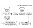
- FIG. 1 is a schematic configuration diagram of a train operation control device according to one embodiment.
- FIG. 2 is an explanatory diagram of a relationship between trains and stations.
- the train concerned TR1 is defined to be controlled to run in accordance with the operation statuses of the train concerned TR1, preceding train, and succeeding train. This is based on the assumption that the operation of the train concerned TR1 is to directly affect the preceding train and the succeeding train alone. Accordingly, in the present embodiment, only the information on the preceding train and the succeeding train are used for determining a departure time and an arrival time of the train concerned TR1 at a current station and at a next station.
- a train operation control device 100 includes a timetable database (DB) 101 containing information on a timetable (diagram: operation plan diagram) on a given day to which vehicles are assigned and a departure time and arrival time calculator 102 which calculates, when the train concerned TR1 as a subject of the operation control has arrived at a station, an estimated departure time at the current station and an estimated arrival time at a station ahead as a next stop for the train concerned TR1, from a delay time representing the operation statuses of a preceding train TR0 and a succeeding train TR2 ahead of and behind the train concerned TR1 in the traveling direction, respectively, respective estimated departure times and estimated arrival times of the preceding train TR0 and the succeeding train TR2, and a margin of time and a delay time of the train concerned TR1.
- DB timetable database
- diagnosis operation plan diagram
- the train operation control device 100 further includes a headway and stop time database (DB) 103 storing previous train headways relative to the timetable and actual values of station stop time, a velocity limit calculator 104 which defines a velocity limit at each block entry position due to the preceding train TR0 at each time point, and a vehicle and route database (DB) 105 storing each notch characteristic and motor and inverter characteristics relative to the occupancy of a vehicle running on a route concerned as well as a velocity limit, a gradient, and a curvature radius at each position on the route concerned.
- DB headway and stop time database
- DB vehicle and route database
- the train operation control device 100 further includes a running profile generator 106 which uses a result of the calculation by the velocity limit calculator 104 as a constraint condition to generate a running profile with a smallest accumulated energy consumption for the train concerned TR1 when running from the current station to the station ahead, and a running information extractor 107 which extracts a velocity limit at each block entry position (entry position in a block section) from a result of the calculation by the running profile generator 106.
- a running profile generator 106 which uses a result of the calculation by the velocity limit calculator 104 as a constraint condition to generate a running profile with a smallest accumulated energy consumption for the train concerned TR1 when running from the current station to the station ahead
- a running information extractor 107 which extracts a velocity limit at each block entry position (entry position in a block section) from a result of the calculation by the running profile generator 106.
- the departure time and arrival time calculator 102 acquires (receives) an arrival time of the train concerned TR1, and a current position, a station of departure (station behind ST2) and a departure time, and an estimated arrival time at a next station (current station ST1) of the succeeding train TR2, and acquires a current position, a station of departure (station ahead ST0) and a departure time, and an estimated arrival time at a next station of the preceding train TR0.
- the departure time and arrival time calculator 102 Upon acquiring the above-mentioned information (data), the departure time and arrival time calculator 102 next acquires an estimated arrival time of the train concerned TR1 as scheduled on timetable, referring to the timetable DB 101. The departure time and arrival time calculator 102 calculates a difference between the estimated arrival time registered in the timetable DB 101 and an actual arrival time to determine whether or not the train concerned TR1 is delayed.
- the departure time and arrival time calculator 102 then calculates an estimated departure time at the current station ST1.
- the estimated departure time at the current station ST1 refers to time obtained by adding a stop time to the arrival time at the current station ST1.
- the stop time refers to either a value prestored (preset) in the timetable DB 101 or a mean value of actual values of the same estimated arrival time of the previous trains.
- the necessary information on the train concerned TR1 includes a delay time, a margin of time, and a stop time, as follows:
- the train operation control device 100 calculates, for the train concerned TR1, at the time when the train concerned TR1 has arrived at the current station ST1, an estimated departure time at the current station ST1, an estimated arrival time at the station ahead ST0, and a length of time (running time) required to run from the current station ST1 to the station ahead ST0.
- the length of time (running time) required for the train concerned TR1 to run from the current station ST1 to the station ahead ST0 is calculated by the following equality:
- the train operation control device 100 calculates an energy-saving running profile for the train concerned TR1 to run from the current station ST1 to the station ahead ST0 in accordance with the following procedure.
- the estimated departure time and estimated arrival time of the train concerned TR1 at the current station ST1 and the station ahead ST0 are determined with the operation statuses of the preceding train TR0 and the succeeding train TR2 taken into account.
- the current statuses of the train concerned TR1, the preceding train TR0, and the succeeding train TR2 are evaluated from their delay times.
- the allowable fixed time ⁇ is a parameter representing a range of time to be regarded as fixed time.
- the stop time at a station in question is adjusted to extend and a train is operated to leave the station at an estimated departure time set on timetable.
- the statuses of the train concerned TR1, the preceding train TR0, and the succeeding train TR2 can be classified into two, i.e., earlier or on-time arrival and delay.
- FIG. 3 is an explanatory diagram of the statuses of the train concerned, the preceding train, and the succeeding train.
- the train concerned TR1 is set to leave the current station ST1 at the estimated departure time set on timetable and arrive at the station ahead ST0 at the estimated arrival time set on timetable.
- the train concerned TR1 can leave the current station ST1 at the estimated departure time set on timetable. This will, however, increase a train headway to the succeeding train TR2. With a longer train headway, a larger number of passengers may wait at the current station ST1 than that in on-schedule traffic until the succeeding train TR2 arrives at the current station ST1, which may result in further delaying the succeeding train TR2 at the current station ST1.
- the train operation control device 100 is configured to define the estimated departure time of the train concerned TR1 at the current station ST1 while adjusting the train headway to the succeeding train TR2 so as not to increase the delay of the train concerned TR1.
- the train operation control device 100 of the train concerned TR1 plans to depart from the current station ST1 at the estimated departure time on timetable + (margin of time of the train concerned TR1 - delay time of the succeeding train TR2) and arrive at the next station at the estimated arrival time on timetable.
- the train operation control device 100 sets the running time of the train concerned TR1 as follows.
- the train concerned runs faster than the running time on timetable by a time (margin of time of the train concerned TR1 - delay time of the succeeding train TR2).
- the train concerned TR1 can accommodate passengers which would otherwise board the succeeding train TR2, and can resolve unbalance in terms of the number of on-board passengers and abate the factor for increasing a delay caused by a concentration of passengers on the succeeding train TR2.
- the train operation control device 100 of the train concerned TR1 plans to leave the current station ST1 at time (estimated departure time at the current station ST1 on timetable + margin of time of the train concerned TR1) and arrive at the station ahead ST0 at the estimated arrival time on timetable. Therefore, the running time of the train concerned TR1 is equal to the minimum running time between the current station ST1 and the station ahead ST0.
- the train concerned TR1 can also accommodate passengers which would otherwise board the succeeding train TR2, and can resolve unbalance in terms of the number of on-board passengers and abate the factor for increasing a delay caused by a concentration of passengers on the succeeding train TR2.
- the train operation control device 100 of the train concerned TR1 operates to make up for the delay.
- the running time of the train concerned TR1 is then defined as follows.
- the train concerned runs faster by the time (margin of time of the train concerned TR1 - delay time of the train concerned TR1).
- the train operation control device 100 of the train concerned TR1 defines a departure time and an estimated arrival time of the train concerned TR1 at the station ahead ST0 as follows:
- the train concerned TR1 cannot return to the regular operation as scheduled till the station ahead ST0 as a next station. However, since its delay is detected at and after the next station, it runs in a shorter running time than that on timetable again and repeatedly runs in a shorter running time, thereby gradually making up for the delay.
- the train operation control device 100 defines the estimated departure time at the current station ST1, taking a block opening time of the preceding train TR0 at the station ahead ST0 into account.
- the train operation control device 100 sets the estimated departure time at the current station ST1, the estimated arrival time at the station ahead ST0, and the running time for the train concerned TR1, as follows.
- the train operation control device 100 defines the estimated arrival time at the next station and the running time of the train concerned TR1 as follows.
- the train operation control device 100 generates an energy-saving running profile for the above running time of the train concerned TR1, considering a longer running time than that on timetable and a velocity limit in the block section due to the presence of the preceding train TR0.
- the train concerned TR1 has to make up for the delay until reaching the station ahead ST0, if possible.
- an earlier departure for the purpose of making up for the delay causes an increase in the train headway relative to the succeeding train TR2, which may cause an increased delay of the succeeding train TR2 at the current station ST1.
- the train operation control device 100 defines the estimated departure time at the current station ST1 to make up for the delay, taking the headway between the train concerned TR1 and the succeeding train TR2 into consideration.
- the train operation control device 100 sets the estimated departure time of the train concerned TR1 at the current station ST1 and the running time of the train concerned TR1 as follows.
- the train operation control device 100 sets the estimated departure time at the current station ST1, the estimated arrival time at the station ahead ST0, and the running time for the train concerned TR1 as follows.
- the train operation control device 100 sets the estimated departure time at the current station ST1 and the estimated arrival time at the station ahead ST0 for the train concerned TR1 as follows.
- the train operation control device 100 of the train concerned TR1 defines the estimated departure time at the current station ST1, taking the block opening time of the preceding train TR0 at the station ahead ST0 into account.
- the operation control device 100 sets, based on the delay time of the succeeding train TR2 and the margin of time of the train concerned TR1, the estimated departure time at the current station ST1, the estimated arrival time at the next station, and the running time for the train concerned TR1, as follows.
- the train operation control device 100 sets the estimated departure time at the current station ST1, the estimated arrival time at the next station, and the running time for the train concerned TR1, as follows.
- the train operation control device 100 sets the estimated departure time at the current station ST1, the estimated arrival time at the next station, and the running time for the train concerned TR1 as follows.
- the train operation control device 100 sets, based on the delay time of the succeeding train TR2, the block opening time of the preceding train TR0 at the next station, and the estimated arrival time of the train concerned TR1 at the next station on timetable, the estimated departure time at the current station ST1, the estimated arrival time at the next station, and the running time for the train concerned TR1, as follows.
- the train operation control device 100 sets, based on the delay time of the succeeding train TR2, the block opening time of the preceding train TR0 at the next station, and the estimated arrival time of the train concerned TR1 at the next station on timetable, the estimated departure time at the current station ST1, the estimated arrival time at the next station, and the running time for the train concerned TR1, as follows.
- the train operation control device 100 sets, based on the delay time of the succeeding train TR2, the block opening time of the preceding train TR0 at the next station, and the estimated arrival time of the train concerned TR1 at the next station on timetable, the estimated departure time at the current station ST1, the estimated arrival time at the next station, and the running time for the train concerned TR1, as follows.
- the train concerned TR1 needs to leave the current station ST1 as early as possible not to hinder the traveling of the succeeding train TR2.
- the train concerned TR1 may not be able to arrive at the current station ST1 earlier than the estimated arrival time of the train concerned TR1 at the station ahead ST0, depending on the amount of delay of the preceding train TR0.
- the train operation control device 100 sets the estimated departure time at the current station ST1, taking the block opening time of the preceding train TR0 at the station ahead ST0 into account.
- the train operation control device 100 sets, based on the delay time and margin of time of the train concerned TR1, the estimated departure time at the current station ST1, the estimated arrival time at the station ahead ST0, and the running time for the train concerned TR1, as follows.
- the train operation control device 100 sets the estimated departure time at the current station ST1, the estimated arrival time at the station ahead ST0, and the running time for the train concerned TR1 as follows.
- the train operation control device 100 sets the estimated departure time at the current station ST1, the estimated arrival time at the station ahead ST0, and the running time for the train concerned TR1 as follows.
- the train operation control device 100 sets the estimated departure time at the current station ST1, the estimated arrival time at the station ahead ST0, and the running time for the train concerned TR1, as follows.
- the train operation control device 100 of the train concerned TR1 has to set the estimated departure time at the current station ST1 and the estimated arrival time at the station ahead ST0, considering the delay times of all the succeeding train TR2, the preceding train TR0, and the train concerned TR1.
- the train operation control device 100 of the train concerned TR1 sets the estimated departure time at the current station ST1, considering the block opening time of the preceding train TR0 at the station ahead ST0.
- the train operation control device 100 sets the following based on the delay time of the succeeding train TR2.
- the train operation control device 100 sets the estimated arrival time at the next station and the running time for the train concerned TR1 as follows.
- the train operation control device 100 sets the estimated departure time at the current station ST1, the estimated arrival time at the next station, and the running time for the train concerned TR1 as follows.
- the train operation control device 100 sets the following based on the delay time of the succeeding train TR2.
- the train operation control device 100 sets the estimated departure time at the current station ST1, the estimated arrival time at the next station, and the running time for the train concerned TR1 as follows.
- the train operation control device 100 sets the estimated departure time at the current station ST1, the estimated arrival time at the next station, and the running time for the train concerned TR1 as follows.
- the velocity limit calculator 104 calculates a velocity limit depending on a necessary time for generating an energy-saving running profile of the train concerned TR1.
- the velocity limit due to the preceding train TR0 is calculated based on the running profile of the preceding train TR0. How to generate the running profile will be specifically described referring to FIG. 4 .
- the running profile is assumed to be generated on the basis of the front position of the train.
- FIG. 4 is an explanatory diagram of how to calculate the velocity limit due to the preceding train TR0.
- the running profile of the preceding train TR0 is considered to be already determined.
- Block sections located between the station of departure (at a 4,700[m] point) and the station of arrival (at a 6,750[m] point) of the preceding train TR0 are concurrently found.
- the train operation control device 100 calculates a time at which the preceding train TR0 passes through a block section, from an elapsed time from a departure time (set to 200 seconds herein) of the preceding train TR0. That corresponds to a passing time at a position forward from the end of each block by the length of the train.
- FIG. 5 is an explanatory diagram of an example of velocity limit setting in a state corresponding to FIG. 4 .
- the train operation control device100 sets the velocity limit for the train concerned TR1 in each block section relative to the elapsed time.
- the velocity limit is set to 0, 30, 60, and 90[km/h] in the block sections in order from the one closer to the preceding train.
- FIG. 5 merely shows one example, and how to decide the velocity limit differs among railway operators, so that it should not be limited to such an example.
- the preceding train TR0 is located in the first block section CA1 from the time 200 seconds to the time 245 seconds, therefore, the velocity limit for the train concerned TR1 in the first block section CA1 is 0 km, that is, stop, to inhibit entry.
- the velocity limit for the train concerned TR1 in the second block section CA2 is set to Okm, that is, stop, to inhibit entry.
- the velocity limit for the train concerned TR1 in the first block section CA1 ahead of the second block section CA2 is set to 30 km.
- the velocity limit for the train concerned TR1 in the third block section CA3 is set to 0 km, that is, stop, to inhibit entry.
- the velocity limit for the train concerned TR1 in the second block section CA2 ahead of the third block section CA3 is set to 30 km.
- the velocity limit for the train concerned TR1 in the first block section CA1 ahead of the second block section CA2 and the third block section CA3 is set to 60 km higher than in the second block section CA2.
- the velocity limit for the train concerned TR1 in the fourth block section CA4 is set to 0km, that is, stop, to inhibit entry.
- the velocity limit for the train concerned TR1 in the third block section CA3 ahead of the fourth block section CA4 is set to 30 km.
- the velocity limit for the train concerned TR1 in the second block section CA2 ahead of the third block section CA3 and the fourth block section CA4 is set to 60 km higher than in the third block section CA3.
- the velocity limit for the train concerned TR1 in the first block section CA1 ahead of the second to the fourth block sections CA2 to CA4 is set to 90 km higher than in the second block section.
- the running profile generator 106 of the train operation control device 100 After setting the velocity limit in each block section in accordance with the position of the preceding train TR0, the running profile generator 106 of the train operation control device 100 then generates an energy-saving running profile between the current station ST1 and the station ahead ST0 during the running time set by the train concerned TR1.
- T represents an elapsed time taken from the station of departure to the station of arrival
- X represents a distance between the station of departure and the station of arrival.
- an evaluation function is found by solving an optimal control problem having a total sum E (accumulated energy consumption) of amounts of consumed energy between the station of departure and the station of arrival, where a control variable for designating the motion of a train is a notch for designating acceleration and deceleration.
- E accumulated energy consumption
- a control variable for designating the motion of a train is a notch for designating acceleration and deceleration.
- the running profile can be regarded as a multi-stage decision making problem of which one of the notches is to be selected at each time point for train operation.
- the states (time, velocity, position) of a train are defined on lattice points to search for a route with the smallest accumulated energy consumption. If multiple routes reaching a given state (t, v, x) are found, only a route with the smallest accumulated energy consumption is stored and the search continues.
- a state space is divided into a lattice in advance, however, a running profile rarely falls on lattice points in general. Therefore, a profile not situated on lattice points is subjected to correction and moved to the lattice points.
- this method faces a problem with a large error from an optimal solution when the profile is subjected to the lattice point correction a large number of times.
- the present embodiment proposes a method of generating a candidate solution upon every stage advancement while checking (pruning) if it can be a candidate of feasible solution at each stage (time), instead of listing all of the candidate solutions for the multi-stage decision making problem.
- pruning is a general-purpose technique known in operations research field for solving a combinatorial optimization problem by generating candidate solutions in generation operation and removing candidates unable to be an optimal solution from a list of candidate solutions in pruning operation.
- the generation operation and the pruning operation are repeated to search for the optimal solution.
- this technique is similar to the complete listing, it is more efficient than the complete listing since it does not search candidate solutions unable to be candidate solutions.
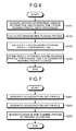
- FIG. 6 is a flowchart of an energy-saving running profile generation process in the embodiment.
- the running profile generator 106 Upon receiving various kinds of data including vehicle information, inter-station information, running time information, the running profile generator 106 acquires, based on the vehicle information and the inter-station information, necessary data for generating a running profile, referring to the vehicle and route DB 105 (step S101).
- the running profile generator 106 generates a minimum-time running profile in the input station interval (step S102).
- FIG. 7 is a flowchart of a minimum-time running profile generation process.
- a minimum-time running polarity generation process generally includes an acceleration limit profile generation process (step S201), a deceleration limit profile generation process (step S202), and a minimum-time running profile generation process by pruning algorithm (step S203).
- the minimum-time control is generally referred to as bang-bang control based on maximum acceleration and maximum deceleration.
- bang-bang control based on maximum acceleration and maximum deceleration.
- a running train cannot be always controlled only by maximum acceleration and maximum deceleration since velocity limits are applied to the train depending mainly on the position of the train. Thus, an area in which a train can be moved at the maximum acceleration and the maximum deceleration is obtained.
- FIG. 8 is an explanatory diagram of conditions in which the maximum acceleration and the maximum deceleration can be applied.
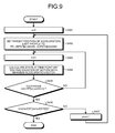
- FIG. 9 is a process flowchart of the acceleration limit profile generation process.
- FIG. 10 is a process flowchart of the deceleration limit profile generation process.
- the maximum acceleration and the maximum deceleration can be applied to a running train in four cases Case 1 to Case 4, as shown in FIG. 8 .
- a velocity limit is expressed by the following structure array:
- positions to be the targets of the acceleration limit profile and the deceleration limit profile are detected.
- the following are defined:
- the positions satisfying the following conditions are set as the target positions of the acceleration limit profile and the deceleration limit profile.
- the array ST includes, for the target positions and the target velocities necessary for generating the acceleration limit profile, all the target positions and target velocities satisfying the above conditions in Case 1 when a train leaves a default station and in case that multiple velocity limits are set.
- the array ST includes, for the target positions and the target velocities necessary for generating the deceleration limit profile, all the target positions and target velocities satisfying the above conditions in Case 2 when a train arrives at a default station and in case that multiple velocity limits are set.
- step S201 first, (velocity, position) at the maximum acceleration and the maximum deceleration is calculated.
- the acceleration limit profile can be simply obtained, given initial velocity and position conditions at the maximum acceleration.
- the running profile generator 106 initializes a variable s to 0(step S401).
- the running profile generator 106 adds 1 to time point i (step S403).
- the running profile generator 106 then calculates a state (v(i),x(i)) at time point i by solving an equation of motion using a maximum acceleration notch (corresponding to a notch position where the maximum acceleration is obtainable) (step S404).
- the running profile generator 106 determines whether or not a velocity v(i) at time point i exceeds a velocity limit vmax, that is, v(i) > vmax, or whether a position x(i) exceeds a target position ST[s].position (step S405).
- step S405 when determining that the velocity v(i) at time point i does not exceed the velocity limit vmax and the position x(i) does not exceed the target position ST[s].position (No in step S405), the running profile generator 106 returns to step S403 and repeats the same processes.
- step S406 When determining that it has not reached the target position of the acceleration limit profile (No in step S406), the running profile generator 106 adds 1 to the variable s (step S407) and returns to step S402 and repeats the same processes.
- the running profile generator 106 ends the acceleration limit profile generation process.
- the running profile generator 106 calculates a deceleration limit profile same as the acceleration limit profile (step S202).
- an initial condition satisfying a termination condition is searched for by iteration.
- the termination condition is given an allowable range ( ⁇ and ⁇ ) to obtain an initial condition satisfying the allowable range.
- the running profile generator 106 then adds 1 to time point i (step S503).
- the running profile generator 106 calculates a state of the train at time point i by solving an equation of motion with the maximum deceleration notch (step S504).
- the running profile generator 106 determines whether or not the velocity v(i) at time point i satisfies the following formula corresponding to the allowable value ⁇ (step S505). 0 ⁇ v i ⁇ ⁇
- step S505 when determining that ⁇ v(i) is satisfied (No in step S505), the running profile generator 106 returns to step S503 and repeats the same processes.
- step S505 when determining that 0 ⁇ v(i) ⁇ ⁇ is satisfied (Yes in step S505), the running profile generator 106 determines whether or not the position x(i) at time point i satisfies the following formula corresponding to the allowable value ⁇ (step S506). x i ⁇ Distance ⁇ ⁇
- step S506 upon determining that x(i)-Distance
- step S506 upon determining that
- ⁇ ⁇ is satisfied (Yes in step S506), the running profile generator 106 determines whether or not it has reached the target position of the deceleration limit profile, that is, s size of ST s / size of ST 0 .
- step S510 upon determining that it has not reached the target position of the deceleration limit profile (No in step S510), the running profile generator 106 adds 1 to the variable s (step S511) and returns to step S502 to repeat the same processes.
- step S510 upon determining that it has reached the target position of the deceleration limit profile (Yes in step S510), the running profile generator 106 ends the deceleration limit profile generation process.
- the deceleration limit profile may be calculated by reverse method in which an equation of motion is solved while time is reversely advanced.
- a solution by the reverse method may differ from a solution by a general numerical solution of differential equations while time is advanced forward.
- the present embodiment adopts the method of more accurately solving differential equations and can obtain more precise deceleration limit profiles than by the reverse method.
- the running profile generator 106 generates a minimum-time running profile by pruning algorithm (step S203).
- FIG. 11 is a process flowchart of a minimum-time running profile generation process.
- variable previous_state a variable current_state
- variable middle_state a variable previous_state
- control program written in a high-level language as C++ or JAVA registered trademark is used to implement the running profile generation process.
- C++ or JAVA can adopt a variable-length array which is changeable in size depending on the number of elements. Because of this, in the present embodiment, candidate solutions at each time point are expressed by variable-length arrays.
- candidate solutions are represented by the following structure arrays in C++:
- the running profile generator 106 solves, for each candidate solution at elapsed time t+1, equations of motion (differential equations) at all the notches to create the number ((number of candidate solutions at elapsed time t) ⁇ (number of notch options)) of candidate solutions, store the candidate solutions as the variable current_state and remove (clear) the variable previous_state from a memory (step S602).
- a state of an n-th candidate solution among the N candidate solutions is defined to be (t, v n (t), x n (t)) as an initial value in a numerical calculation.
- a state thereof at elapsed time t+1 is calculated using an acceleration or deceleration given by a k-th notch NOTCH(k) by a numerical calculation such as 4 th -order Runge-Kutta method.
- 4 th -order Runge-Kutta method is exemplified herein, the numerical solution of equations of motion should not be limited to such an example.
- NK candidate solutions are generated at elapsed time t+1.
- the running profile generator 106 checks if the velocity of each candidate solution in the variable current_state is smaller than the velocity limit defined by the acceleration limit profile, the deceleration limit profile, and the position, to store only the smaller velocities in the variable middle_state and remove (clear) the variable current_state from the memory (step S603).
- the running profile generator 106 sorts the positions in the variable middle_state in descending order and store K larger positions in the variable previous_state, and remove (clear) the variable middle_state from the memory (step S604).
- K the K larger positions are stored for the purpose of preventing the occurrence of no available candidate solutions.
- the running profile generator 106 repeats the process until a condition equivalent to the termination condition with a margin is established (Yes in step S605), same as the deceleration limit profile, and sets the elapsed time t+1 as the minimum running time relative to the elapsed time t at which the candidate solution satisfying such a condition is satisfied (step S607).
- step S605 When determining that the condition is unsatisfied in step S605 (No step in S605), the running profile generator 106 adds (increments) 1 to the elapsed time t (step S606) and returns to step S602 to repeat the same processes.
- FIG. 12 is a process flowchart of the energy-saving running profile generation process.
- the running profile generator 106 generates an energy-saving running profile for a running time T (step S103).
- the running profile generator 106 sets the result of the aforementioned minimum-time running profile as an upper limit value and shifts the result by the running time T along the time axis to set it as a lower limit value (step S700).
- the running profile generator 106 solves, for each candidate solution at elapsed time t+1, equations of motion (differential equations) at all the notches to create the number ((number of candidate solutions at elapsed time t) x (number of notch options)) of candidate solutions, store the candidate solutions as the variable current_state and remove (clear) the variable previous_state from the memory (step S702).
- the running profile generator 106 stores, in the variable middle_state, candidate solutions in the variable current_state satisfying the solution conditions (position, velocity, number of notch switchings, notch duration) and removes (clears) the variable current_state from the memory (step S703).
- the running profile generator 106 sorts the candidate solutions in the variable middle_state at elapsed time t+1 by states (quantized position, quantized velocity, number of notch switchings). It selects one of the candidate solutions with a smallest accumulated energy consumption amount in the state regarded as same, and stores the selected one in the variable previous_state and removes (clears) the variable middle_state from the memory (step S704).
- step S705 when determining that elapsed time t ⁇ running time T holds true (No in step S705), the running profile generator 106 adds 1 (increments, in step S706) to the elapsed time t, and returns to step S702 to repeat the same processes.
- the minimum running time T min is a length of time (minimum running time) taken for the train to run fastest in the station interval.
- a train is assumed to run through the station interval in the running time T min +10 longer than the minimum running time T min by 10 seconds.
- FIG. 13 is a (x-t) graph with time on the abscissa axis and train positions on the vertical axis.
- the upper graph shows a relationship between position x and elapsed time t when the train runs for the minimum running time T min while the lower graph shows the relationship between position x and elapsed time t when the train waits at the station of departure for 10 seconds before running for the minimum running time T min .
- the minimum running time T min represents a running time of the train making the best use of vehicle performance. With the same vehicle characteristics, the train cannot run faster than the speed.
- the minimum running time T min is uniquely obtained.
- the position of the train at elapsed time t when running the same interval in the minimum running time T min is defined to be Upper[t] and the graph moved in parallel by 10 seconds from the graph (t, Upper[t]) of the minimum running time is defined to be (t, Lower[t]).
- FIG. 14 is an explanatory diagram of velocity conditions.
- the running profile for the running time T is located more inside than the minimum-time running profile.
- ⁇ a natural number satisfying X Tmin ( ⁇ -1) ⁇ x (t) ⁇ X Tmin ( ⁇ ) is found from the candidate solutions (t, v(t), x(t)) at elapsed time t.
- a determination is made on whether or not the found ⁇ satisfies the following expression.
- the running profile with less accumulated energy consumption amount simply obtained by the above method may not always provide good operability for drivers.
- a driver may need to perform detailed notch operation at each time point and such an operation may be impractical.
- the number of notch switchings till a certain time point is counted and used as a condition for selecting a candidate solution.
- Candidate solutions with the count exceeding a fixed value are removed from the candidate solutions. For instance, if the number of notch switchings during a certain station interval until a train arrives at a next station is set to 10, only the variables current_state[i] satisfying the condition that a variable storing the number of notch switchings, current_state[i].change_count ⁇ 10 are stored in the variable middle_state.
- a notch continuance condition is also a condition for preventing a notch switching at short time intervals. If the notch continuance condition is set to 5 seconds or more, only the variables current_state[i] satisfying the condition that a variable storing a notch duration, current_state[i]. notch_continuous_time ⁇ 5 are stored in the variable middle_state.
- step S703 the determination is made on all the candidate solutions based on the conditions for position, velocity, number of notch switchings, and notch duration, to store only the candidate solutions satisfying these conditions in the variable middle_state.
- step S704 among the candidate solutions satisfying the respective conditions stored in the variable middle_state in step S703, the velocity and position of the state (t, v(t), x(t)) at elapsed time t+1 are quantized and grouped by the quantized velocity and position, the number of notch switchings, and the notch duration to select only the ones with the smallest accumulated energy consumption amount from the groups.
- FIG. 15A is an explanatory diagram of quantization process (part 1).
- FIG. 15B is an explanatory diagram of quantization process (part 2).
- the values of the position and the values of the velocity can be quantized at a fixed interval as 1[m] and 0.1[m/sec], respectively, or the upper limit value Upper[t] and the lower limit value Lower[t] of the position at time point t can be defined to divide Upper[t] and Lower[t] into N for quantization.
- the position and velocity are quantized at a fixed interval.
- the four conditions for position, velocity, number of notch switchings, and notch duration are set and the states of candidate solutions are defined on the four axes.
- three conditions for position, velocity, and number of notch switchings are described herein.
- FIG. 15A shows a result of pruning candidate solutions at a certain elapsed time t.
- n(t) represents the number of notch switchings at the elapsed time t.
- step S705 the running profile generator 106 determines whether or not the elapsed time t coincides with the running time T, and if not (No in step S705), it proceeds to step S706 to increment the elapsed time t and returns to step S702.
- step S705 when the elapsed time t coincides with the running time T (Yes in step S705), the running profile generator 106 selects one of the candidate solutions with the smallest accumulated energy consumption amount as the optimal solution (step S707).
- step S707 the candidate solutions can be sorted in ascending order of accumulated energy consumption amounts to definitely select the one with the smallest accumulated energy consumption amount therefrom.
- the running profile generator 106 determines a solution with the smallest accumulated energy consumption amount + penalty (v, x) as the optimal solution.
- Penalty (v(T), x(T)) represents a penalty for an error between the state (T, v(T), x(T)) at the elapsed time t and the terminal state (T, 0, X).
- v(T), x(T) In calculating velocity and position by equations of motion, typically, the velocity and position rarely match the terminal state completely because of use of floating-point variables.
- a function, penalty (v(T), x(T)) is prepared to evaluate the accumulated energy consumption amounts containing errors.
- Penalty(v(T),x(T)) is determined by the following expression as disclosed in Nonpatent Literature 1.
- penalty v T , x T v T 2 + x T ⁇ X 2
- the running profile generator 106 After generating the energy-saving running profile of the train concerned TR1 by the afore-mentioned steps, the running profile generator 106 stores a result of the energy-saving running profile for the running time T in a not-shown hard disc drive or semiconductor memory device as a generated running profile storage (step S104).
- the running information extractor 107 extracts a velocity limit value at each block entry point from the generated energy-saving running profile and informs a traffic light of the extracted velocity limit value.
- FIG. 16 is an explanatory diagram of the velocity limit setting by way of example.
- the train concerned TR1 can be operated to make up for an actual delay. At the same time, to deal with the delay of the preceding train, it can be prevented from unnecessarily decelerating and stopping by a stop signal depending on the position of the preceding train, which leads to achieving energy saving.
- the delay of the succeeding train it is also possible to suppress an increase in the delay of the succeeding train caused by an increase in the number of boarding passengers due to an elongated headway as well as to prevent the train concerned TR1 from being delayed due to a delayed departure time.
- the train operation control device includes a control unit as a CPU, a storage as a ROM (Read Only Memory) or a RAM, an external storage as an HDD or a CD drive unit, a display as a display unit, and an input device as a keyboard or a mouse, and can have a hardware configuration including a general-purpose computer.
- a control unit as a CPU
- a storage as a ROM (Read Only Memory) or a RAM
- an external storage as an HDD or a CD drive unit
- a display as a display unit
- an input device as a keyboard or a mouse
- the control program executed in the train operation control device is in an installable or executable file format recorded and offered on a computer readable storage medium including a CD-ROM, a flexible disk (FD), a CD-R, or a DVD(Digital Versatile Disk).
- control program executed in the train operation control device according to the present embodiment can be stored on a computer connected to a network such as the Internet and downloaded via the network.
- the control program executed in the train operation control device according to the present embodiment can be also provided or distributed via a network such as the Internet.
- control program for the train operation control device can be incorporated into an ROM or the like in advance.
Landscapes
- Engineering & Computer Science (AREA)
- Mechanical Engineering (AREA)
- Train Traffic Observation, Control, And Security (AREA)
- Electric Propulsion And Braking For Vehicles (AREA)
Applications Claiming Priority (2)
| Application Number | Priority Date | Filing Date | Title |
|---|---|---|---|
| JP2013250503A JP6453536B2 (ja) | 2013-12-03 | 2013-12-03 | 列車運行制御装置、制御方法及び制御プログラム |
| PCT/JP2014/082036 WO2015083751A1 (fr) | 2013-12-03 | 2014-12-03 | Dispositif de commande, procédé de commande et programme de commande d'exploitation de trains |
Publications (2)
| Publication Number | Publication Date |
|---|---|
| EP3078565A1 true EP3078565A1 (fr) | 2016-10-12 |
| EP3078565A4 EP3078565A4 (fr) | 2017-08-09 |
Family
ID=53273512
Family Applications (1)
| Application Number | Title | Priority Date | Filing Date |
|---|---|---|---|
| EP14868529.0A Withdrawn EP3078565A4 (fr) | 2013-12-03 | 2014-12-03 | Dispositif de commande, procédé de commande et programme de commande d'exploitation de trains |
Country Status (3)
| Country | Link |
|---|---|
| EP (1) | EP3078565A4 (fr) |
| JP (1) | JP6453536B2 (fr) |
| WO (1) | WO2015083751A1 (fr) |
Cited By (1)
| Publication number | Priority date | Publication date | Assignee | Title |
|---|---|---|---|---|
| US11572090B2 (en) | 2018-06-21 | 2023-02-07 | Mitsubishi Electric Corporation | Headway control device |
Families Citing this family (8)
| Publication number | Priority date | Publication date | Assignee | Title |
|---|---|---|---|---|
| JP6446342B2 (ja) * | 2015-08-28 | 2018-12-26 | 株式会社日立製作所 | 運行管理装置 |
| JP2018135018A (ja) * | 2017-02-22 | 2018-08-30 | 東芝インフラシステムズ株式会社 | 運行制御システム |
| JP7080019B2 (ja) * | 2017-06-02 | 2022-06-03 | 株式会社日立製作所 | 列車運行制御装置 |
| JP7324042B2 (ja) * | 2019-05-07 | 2023-08-09 | 株式会社日立製作所 | 輸送計画作成支援システムおよび方法 |
| JP7366866B2 (ja) * | 2020-09-02 | 2023-10-23 | 株式会社日立製作所 | 列車運転支援システムおよび列車運転支援方法 |
| CN112926782B (zh) * | 2021-03-03 | 2022-02-01 | 西南交通大学 | 一种基于惰行-恒速的地铁速度曲线优化方法 |
| JP7824142B2 (ja) * | 2022-04-12 | 2026-03-04 | 株式会社日立製作所 | ダイヤ作成装置、列車制御システム、及びダイヤ作成方法 |
| CN115848458B (zh) * | 2022-11-15 | 2024-11-22 | 北京市地铁运营有限公司 | 基于广义四阶段最优策略的延误场景节能时刻表优化方法 |
Family Cites Families (10)
| Publication number | Priority date | Publication date | Assignee | Title |
|---|---|---|---|---|
| GB2263993B (en) * | 1992-02-06 | 1995-03-22 | Westinghouse Brake & Signal | Regulating a railway vehicle |
| JPH09104347A (ja) | 1995-10-13 | 1997-04-22 | Hitachi Ltd | 列車制御システム |
| JP3854071B2 (ja) * | 2001-01-05 | 2006-12-06 | 株式会社日立製作所 | 列車群制御システム、列車群制御方法、車上ato装置及び地上制御装置 |
| JP3881302B2 (ja) * | 2002-11-06 | 2007-02-14 | 財団法人鉄道総合技術研究所 | 運転曲線作成装置及び運転曲線作成情報 |
| JP4940542B2 (ja) * | 2004-11-24 | 2012-05-30 | 株式会社日立製作所 | 運転整理装置 |
| JP5476070B2 (ja) | 2009-07-23 | 2014-04-23 | 株式会社日立製作所 | 列車制御システム |
| US8774992B2 (en) * | 2010-01-18 | 2014-07-08 | Mitsubishi Electric Corporation | Operation support device and automatic operation device |
| DE102011081993A1 (de) * | 2011-09-01 | 2013-03-07 | Siemens Aktiengesellschaft | Haltezeitberechnungsmodul |
| JP5847596B2 (ja) * | 2012-01-16 | 2016-01-27 | 株式会社東芝 | 車両走行制御装置及び車両走行支援装置 |
| JP6047827B2 (ja) * | 2012-04-27 | 2016-12-21 | 株式会社東芝 | 運行制御装置、運行制御方法及び制御プログラム |
-
2013
- 2013-12-03 JP JP2013250503A patent/JP6453536B2/ja active Active
-
2014
- 2014-12-03 WO PCT/JP2014/082036 patent/WO2015083751A1/fr not_active Ceased
- 2014-12-03 EP EP14868529.0A patent/EP3078565A4/fr not_active Withdrawn
Cited By (1)
| Publication number | Priority date | Publication date | Assignee | Title |
|---|---|---|---|---|
| US11572090B2 (en) | 2018-06-21 | 2023-02-07 | Mitsubishi Electric Corporation | Headway control device |
Also Published As
| Publication number | Publication date |
|---|---|
| WO2015083751A1 (fr) | 2015-06-11 |
| JP6453536B2 (ja) | 2019-01-16 |
| EP3078565A4 (fr) | 2017-08-09 |
| JP2015107687A (ja) | 2015-06-11 |
Similar Documents
| Publication | Publication Date | Title |
|---|---|---|
| EP3078565A1 (fr) | Dispositif de commande, procédé de commande et programme de commande d'exploitation de trains | |
| US8660723B2 (en) | Method for determining run-curves for vehicles in real-time subject to dynamic travel time and speed limit constraint | |
| Ke et al. | Optimisation of train energy-efficient operation for mass rapid transit systems | |
| Bichiou et al. | Real-time optimal intersection control system for automated/cooperative vehicles | |
| Sicre et al. | Modeling and optimizing energy‐efficient manual driving on high‐speed lines | |
| DK3219572T3 (en) | Method of Providing a Driving Recommendation for a Train Driver and Train Driver Advice System | |
| Takeuchi et al. | Moving block signalling dynamics: performance measures and re-starting queued electric trains | |
| WO2013088811A1 (fr) | Procédé pour l'optimisation de la courbe de trajectoire du déplacement d'un véhicule et procédé permettant de déterminer une séquence optique | |
| WO2015008318A1 (fr) | Dispositif de création de courbes opérationnelles, procédé de création de courbes opérationnelles et programme de contrôle de courbes opérationnelles | |
| CN117273371A (zh) | 基于虚拟耦合的重载列车群组运行轨迹优化方法及系统 | |
| Ying et al. | Energy‐efficient train operation with steep track and speed limits: A novel Pontryagin's maximum principle‐based approach for adjoint variable discontinuity cases | |
| CN111717242B (zh) | 一种辅助停车区asa位置的确定方法及相关设备 | |
| Liu et al. | An approach for accurate stopping of high-speed train by using model predictive control | |
| CN119689875A (zh) | 基于运行轨迹优化的虚拟编组列车分布式控制方法及系统 | |
| JP5805051B2 (ja) | 列車自動制御装置 | |
| Liu et al. | A platoon-based eco-driving control mechanism for low-density traffic flow | |
| Gill et al. | Simulation analysis of transmission-based signalling systems for metro applications | |
| Wang et al. | Optimal trajectory planning for trains under a moving block signaling system | |
| EP3656600A1 (fr) | Dispositif d'assistance à l'exploitation ferroviaire, système d'assistance à l'exploitation ferroviaire et procédé d'assistance à l'exploitation ferroviaire | |
| Matsuura et al. | Optimal train speed profiles by dynamic programming with parallel computing and the fine-tuning of mesh | |
| CN115859476B (zh) | 一种高速磁悬浮列车速度曲线生成优化方法 | |
| Li-Xing et al. | Discrete-time movement model of a group of trains on a rail line with stochastic disturbance | |
| Dunbar et al. | A tool for the rapid selection of a railway signalling strategy to implement train control optimisation for energy saving | |
| Wasserburger et al. | Stochastic optimization for energy-efficient cooperative platooning | |
| Ning et al. | Train trajectory optimization for high-speed railways under constraints of successive trains |
Legal Events
| Date | Code | Title | Description |
|---|---|---|---|
| PUAI | Public reference made under article 153(3) epc to a published international application that has entered the european phase |
Free format text: ORIGINAL CODE: 0009012 |
|
| 17P | Request for examination filed |
Effective date: 20160630 |
|
| AK | Designated contracting states |
Kind code of ref document: A1 Designated state(s): AL AT BE BG CH CY CZ DE DK EE ES FI FR GB GR HR HU IE IS IT LI LT LU LV MC MK MT NL NO PL PT RO RS SE SI SK SM TR |
|
| AX | Request for extension of the european patent |
Extension state: BA ME |
|
| DAX | Request for extension of the european patent (deleted) | ||
| A4 | Supplementary search report drawn up and despatched |
Effective date: 20170712 |
|
| RIC1 | Information provided on ipc code assigned before grant |
Ipc: B61L 3/00 20060101AFI20170706BHEP Ipc: B61L 27/00 20060101ALI20170706BHEP |
|
| STAA | Information on the status of an ep patent application or granted ep patent |
Free format text: STATUS: EXAMINATION IS IN PROGRESS |
|
| 17Q | First examination report despatched |
Effective date: 20191011 |
|
| STAA | Information on the status of an ep patent application or granted ep patent |
Free format text: STATUS: THE APPLICATION HAS BEEN WITHDRAWN |
|
| 18W | Application withdrawn |
Effective date: 20200210 |