EP3078613A1 - Équipement pour la collecte et décharge de déchets - Google Patents
Équipement pour la collecte et décharge de déchets Download PDFInfo
- Publication number
- EP3078613A1 EP3078613A1 EP15191064.3A EP15191064A EP3078613A1 EP 3078613 A1 EP3078613 A1 EP 3078613A1 EP 15191064 A EP15191064 A EP 15191064A EP 3078613 A1 EP3078613 A1 EP 3078613A1
- Authority
- EP
- European Patent Office
- Prior art keywords
- equipment
- fact
- chassis
- counter
- tank
- Prior art date
- Legal status (The legal status is an assumption and is not a legal conclusion. Google has not performed a legal analysis and makes no representation as to the accuracy of the status listed.)
- Withdrawn
Links
Images


Classifications
-
- B—PERFORMING OPERATIONS; TRANSPORTING
- B65—CONVEYING; PACKING; STORING; HANDLING THIN OR FILAMENTARY MATERIAL
- B65F—GATHERING OR REMOVAL OF DOMESTIC OR LIKE REFUSE
- B65F3/00—Vehicles particularly adapted for collecting refuse
- B65F3/001—Vehicles particularly adapted for collecting refuse for segregated refuse collecting, e.g. vehicles with several compartments
-
- B—PERFORMING OPERATIONS; TRANSPORTING
- B65—CONVEYING; PACKING; STORING; HANDLING THIN OR FILAMENTARY MATERIAL
- B65F—GATHERING OR REMOVAL OF DOMESTIC OR LIKE REFUSE
- B65F7/00—Cleaning or disinfecting devices combined with refuse receptacles or refuse vehicles
- B65F7/005—Devices, mounted on refuse collecting vehicles, for cleaning or disinfecting refuse receptacles
-
- B—PERFORMING OPERATIONS; TRANSPORTING
- B65—CONVEYING; PACKING; STORING; HANDLING THIN OR FILAMENTARY MATERIAL
- B65F—GATHERING OR REMOVAL OF DOMESTIC OR LIKE REFUSE
- B65F3/00—Vehicles particularly adapted for collecting refuse
- B65F2003/006—Constructional features relating to the tank of the refuse vehicle
- B65F2003/008—Constructional features relating to the tank of the refuse vehicle interchangeable
-
- B—PERFORMING OPERATIONS; TRANSPORTING
- B65—CONVEYING; PACKING; STORING; HANDLING THIN OR FILAMENTARY MATERIAL
- B65F—GATHERING OR REMOVAL OF DOMESTIC OR LIKE REFUSE
- B65F3/00—Vehicles particularly adapted for collecting refuse
- B65F3/02—Vehicles particularly adapted for collecting refuse with means for discharging refuse receptacles thereinto
- B65F2003/0263—Constructional features relating to discharging means
- B65F2003/0269—Constructional features relating to discharging means capable of moving along the side of the vehicle
-
- B—PERFORMING OPERATIONS; TRANSPORTING
- B65—CONVEYING; PACKING; STORING; HANDLING THIN OR FILAMENTARY MATERIAL
- B65F—GATHERING OR REMOVAL OF DOMESTIC OR LIKE REFUSE
- B65F3/00—Vehicles particularly adapted for collecting refuse
- B65F3/02—Vehicles particularly adapted for collecting refuse with means for discharging refuse receptacles thereinto
- B65F2003/0263—Constructional features relating to discharging means
- B65F2003/0276—Constructional features relating to discharging means capable of moving towards or away from the vehicle
-
- B—PERFORMING OPERATIONS; TRANSPORTING
- B65—CONVEYING; PACKING; STORING; HANDLING THIN OR FILAMENTARY MATERIAL
- B65F—GATHERING OR REMOVAL OF DOMESTIC OR LIKE REFUSE
- B65F3/00—Vehicles particularly adapted for collecting refuse
- B65F3/02—Vehicles particularly adapted for collecting refuse with means for discharging refuse receptacles thereinto
- B65F3/04—Linkages, pivoted arms, or pivoted carriers for raising and subsequently tipping receptacles
- B65F3/041—Pivoted arms or pivoted carriers
- B65F3/043—Pivoted arms or pivoted carriers with additional means for keeping the receptacle substantially vertical during raising
- B65F3/045—Four-bar linkages
-
- B—PERFORMING OPERATIONS; TRANSPORTING
- B65—CONVEYING; PACKING; STORING; HANDLING THIN OR FILAMENTARY MATERIAL
- B65F—GATHERING OR REMOVAL OF DOMESTIC OR LIKE REFUSE
- B65F3/00—Vehicles particularly adapted for collecting refuse
- B65F3/14—Vehicles particularly adapted for collecting refuse with devices for charging, distributing or compressing refuse in the interior of the tank of a refuse vehicle
- B65F3/20—Vehicles particularly adapted for collecting refuse with devices for charging, distributing or compressing refuse in the interior of the tank of a refuse vehicle with charging pistons, plates, or the like
- B65F3/208—Vehicles particularly adapted for collecting refuse with devices for charging, distributing or compressing refuse in the interior of the tank of a refuse vehicle with charging pistons, plates, or the like the charging pistons, plates or the like oscillating about a horizontal axis
Definitions
- the present invention relates to a piece of equipment for the collection and discharge of waste, particularly for the differentiated collection of the same.
- Various types of equipment are known for the differentiated waste collection.
- the patent EP 2432713 describes a piece of equipment for the differentiated waste collection comprising a vehicle movable on wheels having a bearing chassis able to support a multi-tank structure having first actuating means able to allow the self-support thereof with respect to the ground and second actuating means able to allow the rotation of each tank for emptying the same.
- the equipment according to EP 2432713 then has a plurality of tanks with a predefined size and each having a relative upper opening through which the waste is introduced inside.
- the known types of equipment also have emptying means for emptying, inside the tanks, the bins containing waste and placed along the road edge.
- the emptying means comprise, for each tank, a relative emptying device able to pick up, raise and rotate a bin so as to allow the introduction of the waste through the upper opening the tank itself is equipped with.
- the main aim of the present invention is to provide a piece of equipment for the collection and discharge of waste, that is flexible to use, i.e. which allows to vary its load capacity and, in addition to the differentiated waste collection and transport, also to wash the bins that are emptied in turn.
- one object of the present invention is to provide a load piece of equipment that is constructively simpler and less expensive than those of known type.
- Another object of the present invention is to provide a piece of equipment for the collection and discharge of waste, which allows to overcome the mentioned drawbacks of the prior art within the ambit of a simple, rational, easy, effective to use and affordable solution.
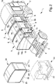
- the equipment 1 comprises a vehicle 2 movable on wheels and having a load-bearing chassis 3.
- the equipment 1 also comprises a counter-chassis 4 associated with the chassis 3 and supporting at least a container 5 for the collection of waste, in turn comprising a relative tank 6 for the collection of waste and lifting and tilting means 7 of the tank itself.
- the lifting and tilting means 7 are interposed between the counter-chassis 4 and the relative tank 6.
- the equipment 1 comprises a plurality of containers 5 each having corresponding lifting and tilting means 7.
- the means 7 are able to move the relative tank 6 between a load position, in which it is arranged resting on the counter-chassis 4, and an unload position, in which it is raised and rotated with respect to the load position in such a way as to allow the outflow of the material contained in its interior.
- the lifting and tilting means 7 comprise at least one articulated parallelogram.
- Each tank 6 defines a relative containment volume 8 delimited by a bottom wall 6a, a front wall 6b and a rear wall 6c opposite to one another, a pair of side walls 6d and an upper wall 6e.
- the front wall 6b and the rear wall 6c are accessible from the outside, while the side walls 6d are, with the tanks 6 in the load position, arranged facing to the side walls 6d of the contiguous tanks 6.
- At least one of the tanks 6 comprises at least a first flap 9 for the introduction of material within the containment volume defined on the front wall 6b.
- the first flap 9 is defined at the lower portion of the relative front wall 6b.
- the first flap 9 is of the tilting type.
- At least one tank 6 comprises at least a second flap 10 for the introduction of material within the relative containment volume 8 which is defined on the upper wall 6e of the tank itself.
- the first flap 9 is therefore accessible to a user irrespective of his/her height, while the second flap 10 is accessible from above and is preferably designed for use by the operators of the sector.
- At least one of the tanks 6 comprises opening means (not shown in the figures), manually operable by the user, of at least one of the first and the second flaps 9 and 10.
- each tank 6 has both the first and the second flaps 9 and 10.
- At least one of the tanks 6 also comprises a third flap 11 for the outflow of material contained within the relative containment volume 8 and defined on the rear wall 6c.
- the third flap 11 is defined at the lower portion of the rear wall 6c and, in the open position, it is arranged substantially parallel to the relative bottom wall 6a to define the extension thereof, so as to facilitate the conveying and direction of the material outwards.
- Control means e.g. of the fluid-operated type, of the third flap 11 are also provided.
- the lifting and tilting means 7 are able to rotate the relative tank 6 downwards from the side of the third flap 11, so as to facilitate the outflow of the material contained within the same.
- At least one tank 6 are arranged compacting means 12 of the material which are placed inside the relative containment volume 8.
- the compacting means 12 comprise at least one compacting element 13 arranged within the relative containment volume 8 so as to split the latter into two chambers 8a, 8b, of which a first chamber 8a communicating with the first and/or with the second flap 9, 10 and a second chamber 8b communicating with the relative third flap 11.
- the compacting element 13 has a first stretch 13a movable in translation close to/away from the relative bottom wall 6a and at least a second stretch 13b associated movable in rotation with the first stretch 13a so as to move the waste entering the first chamber 8a inside the second chamber 8b where they accumulate.
- first stretch 13a is movable in a substantially vertical direction and the second stretch 13b is able to perform a stroke equal to an obtuse angle.
- the waste moved is compacted by accumulation within the second chamber 8b.
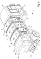
- the equipment 1 also comprises emptying means 14 inside the tanks 6 of bins B containing waste and placed on the ground.
- the emptying means 14 are able to raise the bins B from the ground, carry them to a predefined height, and rotate them so as to allow the emptying thereof inside the tanks 6 through the relative second flaps 10.
- the emptying means 14 comprise at least one emptying device 15 able to pick up and handle the bins B and guide means 16 associated with the counter-chassis 4 and extending along a sliding direction 17; the emptying device 15 is associated movable in translation with the guide means 16 along the sliding direction 17.
- the emptying device 15 is therefore movable continuously along the guide means 16 so as to reach each tank 6.
- the counter-chassis 4 has an elongated shape and the sliding direction 17 extends substantially parallel to the longitudinal axis of the counter-chassis 4.
- the guide means 16 extend along at least one part of the longitudinal extension of the counter-chassis 4.
- the guide means 16 comprise a pair of bars arranged substantially horizontal and parallel to one another.
- the emptying device 15 comprises at least a first portion 18 slidably associated with the guide means 16 and at least a second portion 19 hinged to the first portion 18 and having gripping means of the bins B, schematically represented in the figures by the reference number 19c.
- the second portion 19 is locked in translation to the first portion 18 along the sliding direction 17, whereas it can rotate with respect thereto between a rest position, in which it is moved close to the first portion itself, and a tilting position, in which it is rotated with respect to the rest position.
- the bin B in the rest position of the second portion 19 the bin B is in a substantially vertical position, whereas in the tilting position the bin B is inclined so as to allow the outflow of its content.
- the second portion 19 comprises a main framework 19a, which is hinged to the first portion 18, and a secondary framework 19b, which is associated movable in translation with the main framework 19a and supports the gripping means 19c.
- the secondary framework 19b is then locked in rotation together with the main framework 19a with respect to the first portion 18, whereas it is movable in translation with respect to it.
- the secondary framework 19b is movable with respect to the main framework 19a between a lowered position, in which it allows the picking up and the release of the bins B, and a raised position, in which the bins B are raised from the ground and ready to be emptied.
- the secondary framework 19b protrudes from the main framework 19a, whereas in the raised position it is substantially contained within the main framework itself.
- the second portion 19 is rotated from the rest position towards the tilting one when its secondary framework 19b is located in the raised position.
- the secondary framework 19b is arranged above the first flap 9, so as to allow free access by users.
- the gripping means 19c are associated movable with the secondary framework 19b between a gripping position, in which they are moved away from the secondary framework itself to pick up/release the bins B, and a transport position, in which they are moved close with respect to the secondary framework 19b with respect to the gripping position.
- the gripping means 19c protrude outwards, with reference to the secondary framework 19b, with respect to the transport position.
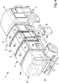
- the counter-chassis 4 comprises at least one module 24, 26 having removable fixing means 22 (schematically represented in the figures) to the counter-chassis 4 and supporting means 23 movable between a transport position, in which the module 24, 26 is supported by the counter-chassis 4, and a work position, in which they are able to self-support the module itself.
- the supporting means 23 are of the type of a plurality of supporting elements arranged below the module 24, 26 and hinged to it, where in the transport position they are raised, whereas in the work position they are lowered so as to self-support the module itself.
- the vehicle 2 is below the module itself with its suspensions lowered, which are then raised so as to raise the module 24, 26 from the ground and disengage the supporting elements 23 which can be brought to the transport position.
- the supporting means 23 comprise a plurality of fluid-operated actuators.
- the module 24, 26 is selected from the group comprising a further tank 26 and a washing device 24 of the bins B.
- Such a washing device 24 is also associated with the counter-chassis 4 by means of the fixing means 22 and can therefore be applied to or removed from the counter-chassis itself depending on the specific requirements.
- the washing device 24 of the type known to the expert in the field, comprises a supporting structure, associable in a removable manner with the counter-chassis 4 by means of the fixing means 22, which supports washing means of the bins B.
- the module 24, 26 is directly associated with the counter-chassis 4 by means of the fixing means 22, i.e. without the interposition of lifting and/or tilting means.
- the counter-chassis 4 then has a first stretch 4a, along which are arranged the containers 5, and a second stretch 4b occupied by the module 24, 26. Conveniently, the guide means 16 extend only along the first stretch 4a.
- the ability to easily replace at least one module allows to choose whether to increase the load capacity of the equipment itself or to wash the bins without it being necessary to use a vehicle different from that used for the collection of waste.
- the provision of emptying means able to serve a plurality of tanks allows to optimize the components of the equipment making the subject of the present invention, by simplifying its manufacturing and reducing the investment costs.
Landscapes
- Engineering & Computer Science (AREA)
- Mechanical Engineering (AREA)
- Refuse-Collection Vehicles (AREA)
- Electrical Discharge Machining, Electrochemical Machining, And Combined Machining (AREA)
- Refuse Collection And Transfer (AREA)
- Filtering Of Dispersed Particles In Gases (AREA)
Applications Claiming Priority (1)
| Application Number | Priority Date | Filing Date | Title |
|---|---|---|---|
| ITMO2014A000303A ITMO20140303A1 (it) | 2014-10-23 | 2014-10-23 | Attrezzatura per il prelievo e lo scarico di rifiuti |
Publications (1)
| Publication Number | Publication Date |
|---|---|
| EP3078613A1 true EP3078613A1 (fr) | 2016-10-12 |
Family
ID=52130651
Family Applications (1)
| Application Number | Title | Priority Date | Filing Date |
|---|---|---|---|
| EP15191064.3A Withdrawn EP3078613A1 (fr) | 2014-10-23 | 2015-10-22 | Équipement pour la collecte et décharge de déchets |
Country Status (2)
| Country | Link |
|---|---|
| EP (1) | EP3078613A1 (fr) |
| IT (1) | ITMO20140303A1 (fr) |
Cited By (3)
| Publication number | Priority date | Publication date | Assignee | Title |
|---|---|---|---|---|
| CN110053910A (zh) * | 2018-01-18 | 2019-07-26 | 南京皇保电动车制造有限公司 | 一种新型分类环卫车 |
| CN111268335A (zh) * | 2020-02-18 | 2020-06-12 | 佛山科学技术学院 | 一种自动收集垃圾桶的装置及应用其的垃圾车 |
| CN114803202A (zh) * | 2022-05-27 | 2022-07-29 | 山东康力医疗器械科技有限公司 | 医疗废液收集装置 |
Citations (6)
| Publication number | Priority date | Publication date | Assignee | Title |
|---|---|---|---|---|
| FR2330612A1 (fr) * | 1975-11-04 | 1977-06-03 | Karlsruhe Augsburg Iweka | Vehicule de collecte et de transport d'ordures |
| DE4303349C1 (de) * | 1993-02-05 | 1994-05-19 | Gert Richter | Transportvorrichtung für die Wertstoffentsorgung |
| CH703637A1 (de) * | 2010-08-26 | 2012-02-29 | System Alpenluft Ag | Ver- und Entsorgungseinrichtung. |
| EP2432713A1 (fr) | 2009-05-22 | 2012-03-28 | Anconambiente S.P.A. | Procédé et équipement de ramassage d'ordures ménagères |
| US20120230803A1 (en) * | 2011-03-11 | 2012-09-13 | Kann Manufacturing Corporation | Linearly extendable collection mechanism for refuse hauling vehicles |
| WO2015193831A1 (fr) * | 2014-06-17 | 2015-12-23 | Forghieri S.R.L. | Équipement destiné à contenir un matériau |
-
2014
- 2014-10-23 IT ITMO2014A000303A patent/ITMO20140303A1/it unknown
-
2015
- 2015-10-22 EP EP15191064.3A patent/EP3078613A1/fr not_active Withdrawn
Patent Citations (6)
| Publication number | Priority date | Publication date | Assignee | Title |
|---|---|---|---|---|
| FR2330612A1 (fr) * | 1975-11-04 | 1977-06-03 | Karlsruhe Augsburg Iweka | Vehicule de collecte et de transport d'ordures |
| DE4303349C1 (de) * | 1993-02-05 | 1994-05-19 | Gert Richter | Transportvorrichtung für die Wertstoffentsorgung |
| EP2432713A1 (fr) | 2009-05-22 | 2012-03-28 | Anconambiente S.P.A. | Procédé et équipement de ramassage d'ordures ménagères |
| CH703637A1 (de) * | 2010-08-26 | 2012-02-29 | System Alpenluft Ag | Ver- und Entsorgungseinrichtung. |
| US20120230803A1 (en) * | 2011-03-11 | 2012-09-13 | Kann Manufacturing Corporation | Linearly extendable collection mechanism for refuse hauling vehicles |
| WO2015193831A1 (fr) * | 2014-06-17 | 2015-12-23 | Forghieri S.R.L. | Équipement destiné à contenir un matériau |
Cited By (5)
| Publication number | Priority date | Publication date | Assignee | Title |
|---|---|---|---|---|
| CN110053910A (zh) * | 2018-01-18 | 2019-07-26 | 南京皇保电动车制造有限公司 | 一种新型分类环卫车 |
| CN111268335A (zh) * | 2020-02-18 | 2020-06-12 | 佛山科学技术学院 | 一种自动收集垃圾桶的装置及应用其的垃圾车 |
| CN111268335B (zh) * | 2020-02-18 | 2021-06-29 | 佛山科学技术学院 | 一种自动收集垃圾桶的装置及应用其的垃圾车 |
| CN114803202A (zh) * | 2022-05-27 | 2022-07-29 | 山东康力医疗器械科技有限公司 | 医疗废液收集装置 |
| CN114803202B (zh) * | 2022-05-27 | 2023-06-20 | 山东康力医疗器械科技有限公司 | 医疗废液收集装置 |
Also Published As
| Publication number | Publication date |
|---|---|
| ITMO20140303A1 (it) | 2016-04-23 |
Similar Documents
| Publication | Publication Date | Title |
|---|---|---|
| NO170070B (no) | Innretning til oppsamling av soeppel | |
| EP3078613A1 (fr) | Équipement pour la collecte et décharge de déchets | |
| US20110056964A1 (en) | Bulk abrasive hopper | |
| US10464747B2 (en) | Bin | |
| KR101728982B1 (ko) | 정미기용 포대 승강장치 | |
| DK2886492T3 (en) | The collection container to a garbage truck | |
| US6443057B1 (en) | Domestic waste treatment system | |
| EP3157846B1 (fr) | Équipement destiné à contenir un matériau | |
| DK169515B1 (da) | Skraldindsamlingssystem | |
| EP3020657A1 (fr) | Dispositif de chargement et procédé d'opération d'un dispositif de chargement | |
| KR101199565B1 (ko) | 수거용기 하역장치가 구비된 음식물쓰레기 수거차량 | |
| GB2223733A (en) | Device for tipping containers | |
| US8720862B2 (en) | Trash can lifting device with lever | |
| US10294024B2 (en) | Skip for domestic and/or industrial waste | |
| US3138275A (en) | Front end loader | |
| CN202369022U (zh) | 一种前上料厨余垃圾箱 | |
| US10336538B1 (en) | Portable hydraulic side-loader system | |
| CN205652011U (zh) | 一种内置有升降垃圾箱的公交车 | |
| CZ287974B6 (cs) | Zvedací vyklápěcí nebo vyklápěcí zařízení k vyprazdňování nádob na odpadky | |
| KR101933855B1 (ko) | 재활용 쓰레기 수거차량용 적재장치 | |
| CN106143548A (zh) | 废品回收运输车 | |
| GB2323772A (en) | Lifting formations for waste containers | |
| CN209618052U (zh) | 一种环保防渗漏垃圾箱 | |
| CN203767390U (zh) | 一种泔水提料装置 | |
| EP3351490B1 (fr) | Système de chargement pour véhicule de collecte de déchets |
Legal Events
| Date | Code | Title | Description |
|---|---|---|---|
| PUAI | Public reference made under article 153(3) epc to a published international application that has entered the european phase |
Free format text: ORIGINAL CODE: 0009012 |
|
| PUAB | Information related to the publication of an a document modified or deleted |
Free format text: ORIGINAL CODE: 0009199EPPU |
|
| PUAI | Public reference made under article 153(3) epc to a published international application that has entered the european phase |
Free format text: ORIGINAL CODE: 0009012 |
|
| AK | Designated contracting states |
Kind code of ref document: A1 Designated state(s): AL AT BE BG CH CY CZ DE DK EE ES FI FR GB GR HR HU IE IS IT LI LT LU LV MC MK MT NL NO PL PT RO RS SE SI SK SM TR |
|
| AX | Request for extension of the european patent |
Extension state: BA ME |
|
| STAA | Information on the status of an ep patent application or granted ep patent |
Free format text: STATUS: REQUEST FOR EXAMINATION WAS MADE |
|
| 17P | Request for examination filed |
Effective date: 20170412 |
|
| RAX | Requested extension states of the european patent have changed |
Extension state: ME Payment date: 20170412 Extension state: BA Payment date: 20170412 |
|
| RBV | Designated contracting states (corrected) |
Designated state(s): AL AT BE BG CH CY CZ DE DK EE ES FI FR GB GR HR HU IE IS IT LI LT LU LV MC MK MT NL NO PL PT RO RS SE SI SK SM TR |
|
| GRAP | Despatch of communication of intention to grant a patent |
Free format text: ORIGINAL CODE: EPIDOSNIGR1 |
|
| STAA | Information on the status of an ep patent application or granted ep patent |
Free format text: STATUS: GRANT OF PATENT IS INTENDED |
|
| INTG | Intention to grant announced |
Effective date: 20190820 |
|
| STAA | Information on the status of an ep patent application or granted ep patent |
Free format text: STATUS: THE APPLICATION IS DEEMED TO BE WITHDRAWN |
|
| 18D | Application deemed to be withdrawn |
Effective date: 20200103 |