EP3078617B1 - Appareil de transport - Google Patents
Appareil de transport Download PDFInfo
- Publication number
- EP3078617B1 EP3078617B1 EP15162524.1A EP15162524A EP3078617B1 EP 3078617 B1 EP3078617 B1 EP 3078617B1 EP 15162524 A EP15162524 A EP 15162524A EP 3078617 B1 EP3078617 B1 EP 3078617B1
- Authority
- EP
- European Patent Office
- Prior art keywords
- guiding surface
- roller
- rollers
- couple
- rotation
- Prior art date
- Legal status (The legal status is an assumption and is not a legal conclusion. Google has not performed a legal analysis and makes no representation as to the accuracy of the status listed.)
- Active
Links
Images

Classifications
-
- B—PERFORMING OPERATIONS; TRANSPORTING
- B65—CONVEYING; PACKING; STORING; HANDLING THIN OR FILAMENTARY MATERIAL
- B65G—TRANSPORT OR STORAGE DEVICES, e.g. CONVEYORS FOR LOADING OR TIPPING, SHOP CONVEYOR SYSTEMS OR PNEUMATIC TUBE CONVEYORS
- B65G54/00—Non-mechanical conveyors not otherwise provided for
- B65G54/02—Non-mechanical conveyors not otherwise provided for electrostatic, electric, or magnetic
-
- B—PERFORMING OPERATIONS; TRANSPORTING
- B61—RAILWAYS
- B61B—RAILWAY SYSTEMS; EQUIPMENT THEREFOR NOT OTHERWISE PROVIDED FOR
- B61B3/00—Elevated railway systems with suspended vehicles
- B61B3/02—Elevated railway systems with suspended vehicles with self-propelled vehicles
-
- B—PERFORMING OPERATIONS; TRANSPORTING
- B65—CONVEYING; PACKING; STORING; HANDLING THIN OR FILAMENTARY MATERIAL
- B65B—MACHINES, APPARATUS OR DEVICES FOR, OR METHODS OF, PACKAGING ARTICLES OR MATERIALS; UNPACKING
- B65B65/00—Details peculiar to packaging machines and not otherwise provided for; Arrangements of such details
-
- B—PERFORMING OPERATIONS; TRANSPORTING
- B65—CONVEYING; PACKING; STORING; HANDLING THIN OR FILAMENTARY MATERIAL
- B65G—TRANSPORT OR STORAGE DEVICES, e.g. CONVEYORS FOR LOADING OR TIPPING, SHOP CONVEYOR SYSTEMS OR PNEUMATIC TUBE CONVEYORS
- B65G35/00—Mechanical conveyors not otherwise provided for
-
- B—PERFORMING OPERATIONS; TRANSPORTING
- B65—CONVEYING; PACKING; STORING; HANDLING THIN OR FILAMENTARY MATERIAL
- B65G—TRANSPORT OR STORAGE DEVICES, e.g. CONVEYORS FOR LOADING OR TIPPING, SHOP CONVEYOR SYSTEMS OR PNEUMATIC TUBE CONVEYORS
- B65G2201/00—Indexing codes relating to handling devices, e.g. conveyors, characterised by the type of product or load being conveyed or handled
- B65G2201/02—Articles
-
- B—PERFORMING OPERATIONS; TRANSPORTING
- B65—CONVEYING; PACKING; STORING; HANDLING THIN OR FILAMENTARY MATERIAL
- B65G—TRANSPORT OR STORAGE DEVICES, e.g. CONVEYORS FOR LOADING OR TIPPING, SHOP CONVEYOR SYSTEMS OR PNEUMATIC TUBE CONVEYORS
- B65G2812/00—Indexing codes relating to the kind or type of conveyors
- B65G2812/99—Conveyor systems not otherwise provided for
Definitions
- the track comprises guide elements and the movable elements comprise wheels slideable along the guide elements of the track.
- the position of the movable element with respect to the track has to be extremely precise, in order to assure that the machine works in a proper way.
- US4716346 dislcoses a transporting apparatus according to the preamble of claim 1.
- a conveying apparatus of the type including a plurality of driving means disposed in the spaced relation along a track so as to allow a carriage to move on the track under the influence of inertia with the aid of propulsive force or reverse propulsive force which is generated by the plural driving means.
- the track has at least a curve and another driving means is disposed at the position upstream of the curve as seen in the direction of transportation of the carriage.
- a desired speed is so determined that centrifugal force exerted on the carriage is maintained at a level equal to or lower than a predetermined value.
- Speed controlling is effected in such a manner that the carriage is decelerated or accelerated from the moving speed detected at the time before it enters the curve to the desired speed by means of the last-mentioned driving means.
- FR2367938 discloses a linear bearing that utilises an extruded square bar of ordinary commercial quality.
- the bar is guided by pairs of rollers which run on each face of the bar.
- the rollers run on ball bearings on the shafts which are supported by four smaller square bars which fit in a sheet metal housing.
- the play between the central bar and the rollers is adjusted by screws which screw into tapped holes in the housing.
- the design can be adapted to use a central bar of circular cross section.
- An object of the invention is to improve the known transporting apparatus.
- Another object of the invention is to provide a transporting apparatus that, when used in a machine, is able to carry a tool of the machine and position the tool in a very accurate and precise way.
- the movable elements 3 are independently movable along the track 2 by individually controlling the solenoids 101.
- the movable elements 3 are arranged for carrying an object.
- the above-mentioned object may be a device, or a tool, that carries out a certain operation in the machine.
- the device, or tool in case of a packaging machine for manufacturing packages by folding, filling and sealing a web of packaging material, can be a forming element for forming a package, or a moulding element for moulding plastics on the packaging material to obtain an opening device of the package.
- the track 2 comprises a guiding member 4 on which the movable elements 3 are movable.
- the guiding member 4 also comprises a second plate 5b projecting from a second side 61, opposite to the first side 60, of the frame 6.
- the guiding member 4 has a first linear branch 7 and a second linear branch 8.
- the first linear branch 7 and the second linear branch 8 are substantially parallel to each other.
- the guiding member 4 further comprises a first curved branch 9 and a second curved branch (not shown) interposed between the first linear branch 7 and the second linear branch 8.
- the first curved branch 9 and the second curved branch are opposite to each other. In this way, the guiding member 4 has a substantially oval longitudinal cross section.
- the movable elements 3 comprise a supporting body 14 arranged for supporting the above-mentioned object, i.e. the device, or tool, in the case of a machine.
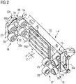
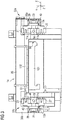
- the movable elements 3 further comprise a first couple of rollers 15, a further first couple of rollers 16, a second couple of rollers 17, a further second couple of rollers 18, a third couple of rollers 19 and a further third couple of rollers 20 that are rotatably connected to the supporting body 14 and slidably coupled with the guiding member 4.
- the guiding member 4 comprises a first guiding surface 11a and a further first guiding surface 11b facing towards the supporting body 14, a second guiding surface 12a and a further second guiding surface 12b facing away from the supporting body 14, and a third guiding surface 13a arranged transversally with respect to the first guiding surface 11a and the second guiding surface 12a, and a further third guiding surface 13b arranged transversally with respect to the further first guiding surface 11b and the further second guiding surface 12b.
- the first guiding surface 11a and the further first guiding surface 11b are mutually aligned.
- the second guiding surface 12a and the further second guiding surface 12b are mutually aligned.
- the second guiding surface 12a is arranged on the opposite side of the supporting body 14 with respect to the first guiding surface 11a.
- the further second guiding surface 12b is arranged on the opposite side of the supporting body 14 with respect to the further first guiding surface 11b.
- the third guiding surface 13a is perpendicular to the first guiding surface 11a and to the second guiding surface 12a.
- the further third guiding surface 13b is perpendicular to the further first guiding surface 11b and to the further second guiding surface 12b.
- the third guiding surface 13a is parallel to the further third guiding surface 13b.
- the second plate 5b comprises the further first guiding surface 11b, the further second guiding surface 12b and the further third guiding surface 13b.
- the first couple of rollers 15 slides along the first guiding surface 11a.
- the further first couple of rollers 16 slides along the further first guiding surface 11b.
- the further second couple of rollers 18 slides along the further second guiding surface 12b.
- the third couple of rollers 19 slides along the third guiding surface 13a.
- the further third couple of rollers 20 slides along the further third guiding surface 13b.
- the first couple of rollers 15 comprises a first roller 21 and a second roller 22.
- the further first couple of rollers 16 comprises a third roller 23 and a fourth roller 24.
- the second couple of rollers 17 comprises a fifth roller 25 and a sixth roller 26.
- the further second couple of rollers 18 comprises a seventh roller 27 and an eighth roller 28.
- the third couple of rollers 19 comprises a ninth roller 29 and a tenth roller 30.
- the further third couple of rollers 20 comprises an eleventh roller 31 and a twelfth roller 32.
- the movable elements 3 slide on the track 2 along an advancing direction A.
- the movable elements 3 move on the track 2 along an axis Z, parallel to the advancing direction A.
- the first roller 21, the second roller 22, the third roller 23, the fourth roller 24, the fifth roller 25, the sixth roller 26, the seventh roller 27 and the eighth roller 28 prevents the movable element 3 from moving along a further axis Y perpendicular to axis Z and also perpendicular to the first guiding surface 11a, the further first guiding surface 11b, the second guiding surface 12a and the further second guiding surface 12b.
- the ninth roller 29, the tenth roller 30, the eleventh roller 31 and the twelfth roller 32 prevent the movable element 3 from moving along a still further axis X perpendicular to axis Z and also perpendicular to the third guiding surface 13a and the further third guiding surface 13b.
- Axis Z, further axis Y and still further axis X are perpendicular to each other.
- Axis Z, further axis Y and still further axis X are to be intended as integral with the movable element 3, as the movable element 3 moves along the track 4.
- the second roller 22 and the fifth roller 25, and the fourth roller 24 and the seventh roller 27, prevent the movable elements 3 from rotating around still further axis X, in a clockwise direction.
- the first roller 21 and the sixth roller 26, and the third roller 23 and the eighth roller 28, prevent the movable elements 3 from rotating around still further axis X, in a counter-clockwise direction.
- the tenth roller 30 and the eleventh roller 31 prevent the movable elements 3 from rotating around further axis Y, in a clockwise direction.
- the ninth roller 29 and the twelfth roller 32 prevent the movable elements 3 from rotating around further axis Y, in a counter-clockwise direction.
- the first roller 21 and the second roller 22, and the seventh roller 27 and the eighth roller 28, prevent the movable elements 3 from rotating around axis Z, in a clockwise direction.
- the fifth roller 25 and the sixth roller 26, and the third roller 23 and the fourth roller 24, prevent the movable elements 3 from rotating around axis Z, in a counter-clockwise direction.
- the rotation axes of the rollers of the first couple of rollers 15, i.e. the rotation axes of the first roller 21 and the second roller 22, are parallel to still further axis X and perpendicular to the third guiding surface 13a and the further third guiding surface 13b.
- the rotation axes of the rollers of the further first couple of rollers 16, i.e. the rotation axes of the third roller 23 and the fourth roller 24, are parallel to still further axis X and perpendicular to the third guiding surface 13a and the further first guiding surface 13b.
- the rotation axes of the rollers of the second couple of rollers 17, i.e. the rotation axes of the fifth roller 25 and the sixth roller 26, are parallel to still further axis X and perpendicular to the third guiding surface 13a and the further third guiding surface 13b.
- the rotation axes of the rollers of the further second couple of rollers 18, i.e. the rotation axes of the seventh roller 27 and the eighth roller 28, are parallel to still further axis X and perpendicular to the third guiding surface 13a and the further second guiding surface 13b.
- the rotation axes of the rollers of the third couple of rollers 19, i.e. the rotation axes of the ninth roller 29 and the tenth roller 30, are parallel to further axis Y and perpendicular to the first guiding surface 11a, the further first guiding surface 11b, the second guiding surface 12a and the further second guiding surface 12b.
- the rotation axes of the rollers of the further third couple of rollers 20, i.e. the rotation axes of the eleventh roller 31 and the twelfth roller 32, are parallel to further axis Y and perpendicular to the first guiding surface 11a, the further first guiding surface 11b, the second guiding surface 12a and the further second guiding surface 12b.
- the first roller 21, the second roller 22, the third roller 23, the fourth roller 24, the fifth roller 25, the sixth roller 26, the seventh roller 27, the eighth roller 28, the ninth roller 29, the tenth roller 30, the eleventh roller 31 and the twelfth roller 32 are mounted on the supporting body 14 by means of rotation units 33, each supporting a group of rollers 34.
- Each group of rollers 34 comprises three rollers, a roller belonging to the first couple of rollers 15 or to the further first couple of rollers 16, a further roller belonging to the second couple of rollers 17 or, respectively, to the further second couple of rollers 18 and a still further roller belonging to the third couple of rollers 19 or, respectively, to the further third couple of rollers 20.
- the supporting body 14 comprises a front part 35 substantially extending in a plane defined by axis Z and still further axis X and a first side part 36a and a second side part 36b protruding from opposite sides of the front part 35 and each substantially extending in a plane defined by axis Z and further axis Y.
- the front part 35 is arranged to support the above-mentioned object.
- Each rotation unit 33 comprises a rotation element 37 that is rotatably coupled to the supporting body 14, in particular to the first side part 36a or to the second side part 36b, and is rotatable around a rotation axis parallel to the still further axis X, i.e. perpendicular to the third guiding surface 13a and to the further third guiding surface 13b.
- Each movable element 3 comprises four rotation units 33, in particular a first rotation unit 33a (shown in Figure 3 ) and a second rotation unit (not shown) rotatably coupled to the first side part 36a, and a third rotation unit 33c (shown in Figures 2 and 3 ) and a fourth rotation unit 33d (shown in Figure 2 ) rotatably coupled to the second side part 36b.
- the first rotation unit 33a comprises the first roller 21, the fifth roller 25 and the ninth roller 29.
- the second rotation unit comprises the second roller 22, the sixth roller 26 and the tenth roller 30.
- the third rotation unit 33c comprises the third roller 23, the seventh roller 27 and the eleventh roller 31.
- the fourth rotation unit 33d comprises the fourth roller 24, the eighth roller 28 and the twelfth roller 32.
- roller 41 corresponds to the fifth roller 25
- further roller 42 corresponds to the first roller 21
- still further roller 43 corresponds to ninth roller 29.
- roller 41 corresponds to the sixth roller 26
- further roller 42 corresponds to the second roller 22
- still further roller 43 corresponds to tenth roller 30.
- roller 41 corresponds to the third roller 23
- further roller 42 corresponds to the seventh roller 27
- still further roller 43 corresponds to eleventh roller 31.
- roller 41 corresponds to the fourth roller 24
- roller 42 corresponds to the eighth roller 28
- still further roller 43 corresponds to twelfth roller 32.
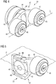
- the rotation element 37 comprises a shaft portion 38 received in a hole 39 of the first side part 36a, or the second side part 36b.
- a bearing 40 is interposed between the shaft portion 38 and the first side part 36a, or the second side part 36b.
- the rotation element 37 further comprises a bracket portion 44 that comprises a pin 45 that rotatably supports the roller 41 and a further pin 46 that rotatably supports the further roller 42.
- the rotation element 37 further comprises a seat 47 that receives the still further roller 43.
- the rotation element 37 comprises a still further pin 48 protruding into the seat 47 and rotatably supporting the still further roller 43.
- the axes of rotation of the roller 41 and the further roller 42 are aligned on a line L.
- the axes of rotation of the roller 41, the further roller 42 and the still further roller 43 are arranged in a plane P.
- the minimum distance between the roller 41 and the further roller 42 is less than the width of the first plate 5a, or the second plate 5b, measured along further axis Y. In other words, the minimum distance between the roller 41 and the further roller 42 is less than the distance between the first guiding surface 11a and the second guiding surface 12a or, respectively, the further first guiding surface 11b and the further second guiding surface 12b.
- roller 41 and the further roller 42 are mounted on the guiding member with interference, so as to avoid play, or clearance, between the movable elements 3 and the track 2.
- the movable elements 3 are moved on the track 2 independently from each other by individually controlling the corresponding solenoids.
- the first roller 21, the second roller 22, the third roller 23, the fourth roller 24, the fifth roller 25, the sixth roller 26, the seventh roller 27, the eighth roller 28, the ninth roller 29, the tenth roller 30, the eleventh roller 31 and the twelfth roller 32 precisely guide the movable elements 3 in the advancing direction A, i.e. along axis Z and prevent any other movement of the movable elements 3 along still further axis X and further axis Y, and around still further axis X, further axis Y and axis Z.
- the line L is always kept perpendicular to the first guiding surface 11a and the second guiding surface 12a or, respectively, to the further first guiding surface 11b and the further second guiding surface 12b.
- the line L is always so oriented as to pass through the centre of curvature of the first curved branch 9, or - respectively - the second curved branch.
- the transporting apparatus 1 has high stiffness, and the movable elements 3 may carry rather heavy objects without compromising a good positioning of the objects.
- the above-mentioned devices, or tools can be precisely positioned also in case they are cantilevered to the movable elements 3 and, therefore, the movable elements 3 are subjected to significant loads.
- the movable elements 3 are properly guided both along the first linear branch 7 and second linear branch 8, and the first curved branch 9 and second curved branch.
Landscapes
- Engineering & Computer Science (AREA)
- Mechanical Engineering (AREA)
- Transportation (AREA)
- Rollers For Roller Conveyors For Transfer (AREA)
- Bearings For Parts Moving Linearly (AREA)
- Non-Mechanical Conveyors (AREA)
- Auxiliary Devices For And Details Of Packaging Control (AREA)
- Basic Packing Technique (AREA)
- Machine Tool Units (AREA)
Claims (15)
- Appareil de transport, comprenant une piste (2) et au moins un élément mobile (3) déplaçable le long de ladite piste (2), ledit élément mobile (3) comprenant un corps de support (14), ladite piste (2) présentant une première surface de guidage (11a) et une première surface de guidage supplémentaire (11b) orientée en direction dudit corps de support (14), une deuxième surface de guidage (12a) et une deuxième surface de guidage supplémentaire (12b) tournant le dos audit corps de support (14), et une troisième surface de guidage (13a) agencée transversalement à ladite première surface de guidage (11a) et à ladite deuxième surface de guidage (12a) et une troisième surface de guidage supplémentaire (13b) agencée transversalement à ladite première surface de guidage supplémentaire (11b) et à ladite deuxième surface de guidage supplémentaire (12b), dans lequel ledit élément mobile (3) comprend un premier couple de rouleaux (15) couplés de façon coulissante à ladite première surface de guidage (11a), un premier couple de rouleaux supplémentaire (16) couplés de façon coulissante à ladite première surface de guidage supplémentaire (11b), un deuxième couple de rouleaux (17) couplés de façon coulissante à ladite deuxième surface de guidage (12a), un deuxième couple de rouleaux supplémentaire (18) couplés de façon coulissante à ladite deuxième surface de guidage supplémentaire (12b), un troisième couple de rouleaux (19) couplés de façon coulissante à ladite troisième surface de guidage (13a) et un troisième couple de rouleaux supplémentaire (20) couplés de façon coulissante à ladite troisième surface de guidage supplémentaire (13b), caractérisé en ce que ledit appareil de transport comprend en outre quatre unités de rotation (33) supportant chacune un groupe de trois rouleaux (34), chaque groupe de trois rouleaux (34) comprenant un rouleau (41; 42) appartenant audit premier couple de rouleaux (15) ou audit premier couple de rouleaux supplémentaire (16), un rouleau supplémentaire (42; 41) appartenant audit deuxième couple de rouleaux (17) ou, respectivement, audit deuxième couple de rouleaux supplémentaire (18) et encore un rouleau supplémentaire (43) appartenant audit troisième couple de rouleaux (19) ou, respectivement, audit troisième couple de rouleaux supplémentaire (20).
- Appareil de transport selon la revendication 1, dans lequel ladite première surface de guidage (11a) et ladite première surface de guidage supplémentaire (11b) sont mutuellement alignées, dans lequel ladite deuxième surface de guidage (12a) et ladite deuxième surface de guidage supplémentaire (12b) sont mutuellement alignées et parallèles à ladite première surface de guidage (11a) et à ladite première surface de guidage supplémentaire (11b), et dans lequel ladite troisième surface de guidage (13a) est perpendiculaire à ladite première surface de guidage (11a) et à ladite deuxième surface de guidage (12a), et ladite troisième surface de guidage supplémentaire (13b) est perpendiculaire à ladite première surface de guidage supplémentaire (11b) et à ladite deuxième surface de guidage supplémentaire (12b) .
- Appareil de transport selon la revendication 1, ou 2, dans lequel les axes de rotation des rouleaux dudit premier couple de rouleaux (15) sont perpendiculaires à ladite troisième surface de guidage (13a) et à ladite troisième surface de guidage supplémentaire (13b), dans lequel les axes de rotation des rouleaux dudit premier couple de rouleaux supplémentaire (16) sont perpendiculaires à ladite troisième surface de guidage (13a) et à ladite première surface de guidage supplémentaire (13b), dans lequel les axes de rotation des rouleaux dudit deuxième couple de rouleaux (17) sont perpendiculaires à ladite troisième surface de guidage (13a) et à ladite troisième surface de guidage supplémentaire (13b), dans lequel les axes de rotation des rouleaux dudit deuxième couple de rouleaux supplémentaire (18) sont perpendiculaires à ladite troisième surface de guidage (13a) et à ladite deuxième surface de guidage supplémentaire (13b), dans lequel les axes de rotation des rouleaux dudit troisième couple de rouleaux (19) sont perpendiculaires à ladite première surface de guidage (11a), à ladite première surface de guidage supplémentaire (11b), à ladite deuxième surface de guidage (12a) et à ladite deuxième surface de guidage supplémentaire (12b), et dans lequel les axes de rotation des rouleaux dudit troisième couple de rouleaux supplémentaire (20) sont perpendiculaires à ladite première surface de guidage (11a), à ladite première surface de guidage supplémentaire (11b), à ladite deuxième surface de guidage (12a) et à ladite deuxième surface de guidage supplémentaire (12b).
- Appareil de transport selon l'une quelconque des revendications précédentes, dans lequel ladite deuxième surface de guidage (12a) est agencée sur le côté opposé dudit corps de support (14) par rapport à ladite première surface de guidage (11a), et dans lequel ladite deuxième surface de guidage supplémentaire (12b) est agencée sur le côté opposé dudit corps de support (14) par rapport à ladite première surface de guidage supplémentaire (11b).
- Appareil de transport selon l'une quelconque des revendications précédentes, et en outre dans lequel ladite unité de rotation (33) comprend un élément de rotation (37) qui est couplé de façon rotative audit corps de support (14) et qui est rotatif autour d'un axe de rotation perpendiculaire à ladite troisième surface de guidage (13a) et à ladite troisième surface de guidage supplémentaire (13b).
- Appareil de transport selon la revendication 5, dans lequel ledit élément de rotation (37) comprend une partie de console (44) pourvue d'une broche (45; 46) qui supporte de façon rotative ledit rouleau (41; 42) et d'une broche supplémentaire (46; 45) qui supporte de façon rotative ledit rouleau supplémentaire (42; 41).
- Appareil de transport selon la revendication 5, ou 6, dans lequel ledit élément de rotation (37) comprend en outre un siège (47) qui reçoit ledit encore un rouleau supplémentaire (43) et encore une broche supplémentaire (48) qui fait saillie dans ledit siège (47) et qui supporte de façon rotative ledit encore un rouleau supplémentaire (43).
- Appareil de transport selon l'une quelconque des revendications précédentes, dans lequel les axes de rotation dudit rouleau (41; 42) et dudit rouleau supplémentaire (42; 41) sont alignés sur une ligne (L) qui, lorsque ledit élément mobile (3) se déplace le long de ladite piste (2), reste perpendiculaire à ladite première surface de guidage (11a), à ladite première surface de guidage supplémentaire (11b), à ladite deuxième surface de guidage (12a) et à ladite deuxième surface de guidage supplémentaire (12b).
- Appareil de transport selon l'une quelconque des revendications précédentes, dans lequel les axes de rotation dudit rouleau (41; 42), dudit rouleau supplémentaire (42; 41) et dudit encore un rouleau supplémentaire (43) sont agencés dans un plan (P).
- Appareil de transport selon l'une quelconque des revendications précédentes, dans lequel ledit premier couple de rouleaux (15) comprend un premier rouleau (21) et un deuxième rouleau (22), ledit premier couple de rouleaux supplémentaire (16) comprend un troisième rouleau (23) et un quatrième rouleau (24), ledit deuxième couple de rouleaux (17) comprend un cinquième rouleau (25) et un sixième rouleau (26), ledit deuxième couple de rouleaux supplémentaire (18) comprend un septième rouleau (27) et un huitième rouleau (28), ledit troisième couple de rouleaux (19) comprend un neuvième rouleau (29) et un dixième rouleau (30) et ledit troisième couple de rouleaux supplémentaire (20) comprend un onzième rouleau (31) et un douzième rouleau (32) .
- Appareil de transport selon la revendication 10, dans lequel ledit élément mobile (3) comprend quatre unités de rotation (33), une première unité de rotation (33a) comprenant ledit premier rouleau (21), ledit cinquième rouleau (25) et ledit neuvième rouleau (29), une deuxième unité de rotation comprenant ledit deuxième rouleau (22), ledit sixième rouleau (26) et ledit dixième rouleau (30), une troisième unité de rotation (33c) comprenant ledit troisième rouleau (23), ledit septième rouleau (27) et ledit onzième rouleau (31), et une quatrième unité de rotation (33d) comprenant ledit quatrième rouleau (24), ledit huitième rouleau (28) et ledit douzième rouleau (32).
- Appareil de transport selon la revendication 11, dans lequel ledit corps de support (14) comprend une partie avant (35), et une première partie latérale (36a) et une deuxième partie latérale (36b) qui fait saillie à partir de côtés opposés de ladite partie avant (35), ladite première unité de rotation (33a) et ladite deuxième unité de rotation étant couplées de façon rotative à ladite première partie latérale (36a), et ladite troisième unité de rotation (33c) et ladite quatrième unité de rotation (33d) étant couplées de façon rotative à ladite deuxième partie latérale (36b).
- Appareil de transport selon l'une quelconque des revendications précédentes, dans lequel ladite piste (2) comprend un élément de guidage (4), ledit élément de guidage (4) étant pourvu, à un premier côté de celui-ci, de ladite première surface de guidage (11a), de ladite deuxième surface de guidage (12a) et de ladite troisième surface de guidage (13a), ledit élément de guidage (4) étant en outre pourvu, à un deuxième côté de celui-ci, opposé audit premier côté, de ladite première surface de guidage supplémentaire (11b), de ladite deuxième surface de guidage supplémentaire (12b) et de ladite troisième surface de guidage supplémentaire (13b), ledit élément de guidage (4) présentant une première branche linéaire (7), une deuxième branche linéaire (8), une première branche courbe (9) et une deuxième branche courbe, ladite première branche courbe (9) et ladite deuxième branche courbe étant interposées entre ladite première branche linéaire (7) et ladite deuxième branche linéaire (8).
- Appareil de transport selon l'une quelconque des revendications précédentes, et comprenant une pluralité d'éléments mobiles (3), ladite piste (2) contenant des solénoïdes excitables individuellement, et lesdits éléments mobiles (3) contenant des aimants permanents (3), ou lesdits élément mobiles (3) contenant des solénoïdes excitables individuellement et ladite piste (2) contenant des aimants permanents, lesdits éléments mobiles (3) étant déplaçables de façon indépendante le long de ladite piste (2) en commandant individuellement lesdits solénoïdes.
- Machine d'emballage pour produire des paquets à partir d'un matériau d'emballage, ladite machine d'emballage comprenant une pluralité d'outils agencés de manière à exécuter une opération sur ledit matériau d'emballage, ladite machine d'emballage comprenant en outre un appareil de transport selon l'une quelconque des revendications 1 à 14, dans lequel chacun desdits éléments mobiles (3) supporte un desdits outils.
Priority Applications (11)
| Application Number | Priority Date | Filing Date | Title |
|---|---|---|---|
| EP15162524.1A EP3078617B1 (fr) | 2015-04-07 | 2015-04-07 | Appareil de transport |
| ES15162524.1T ES2682936T3 (es) | 2015-04-07 | 2015-04-07 | Aparato de transporte |
| CN201680014053.6A CN107406205B (zh) | 2015-04-07 | 2016-03-24 | 运输设备 |
| BR112017020330-8A BR112017020330B1 (pt) | 2015-04-07 | 2016-03-24 | Aparelho de transporte, e, máquina de acondicionamento |
| RU2017134694A RU2666084C1 (ru) | 2015-04-07 | 2016-03-24 | Транспортирующее устройство |
| MX2017012823A MX383046B (es) | 2015-04-07 | 2016-03-24 | Aparato de transportacion. |
| JP2017552861A JP6644084B2 (ja) | 2015-04-07 | 2016-03-24 | 搬送装置 |
| US15/558,665 US10189655B2 (en) | 2015-04-07 | 2016-03-24 | Transporting apparatus |
| KR1020177026997A KR101858916B1 (ko) | 2015-04-07 | 2016-03-24 | 운송장치 |
| PCT/EP2016/056501 WO2016162217A1 (fr) | 2015-04-07 | 2016-03-24 | Appareil de transport |
| JP2019175011A JP6794519B2 (ja) | 2015-04-07 | 2019-09-26 | 搬送装置 |
Applications Claiming Priority (1)
| Application Number | Priority Date | Filing Date | Title |
|---|---|---|---|
| EP15162524.1A EP3078617B1 (fr) | 2015-04-07 | 2015-04-07 | Appareil de transport |
Publications (2)
| Publication Number | Publication Date |
|---|---|
| EP3078617A1 EP3078617A1 (fr) | 2016-10-12 |
| EP3078617B1 true EP3078617B1 (fr) | 2018-05-23 |
Family
ID=52823497
Family Applications (1)
| Application Number | Title | Priority Date | Filing Date |
|---|---|---|---|
| EP15162524.1A Active EP3078617B1 (fr) | 2015-04-07 | 2015-04-07 | Appareil de transport |
Country Status (10)
| Country | Link |
|---|---|
| US (1) | US10189655B2 (fr) |
| EP (1) | EP3078617B1 (fr) |
| JP (2) | JP6644084B2 (fr) |
| KR (1) | KR101858916B1 (fr) |
| CN (1) | CN107406205B (fr) |
| BR (1) | BR112017020330B1 (fr) |
| ES (1) | ES2682936T3 (fr) |
| MX (1) | MX383046B (fr) |
| RU (1) | RU2666084C1 (fr) |
| WO (1) | WO2016162217A1 (fr) |
Families Citing this family (9)
| Publication number | Priority date | Publication date | Assignee | Title |
|---|---|---|---|---|
| ES2682936T3 (es) * | 2015-04-07 | 2018-09-24 | Tetra Laval Holdings & Finance Sa | Aparato de transporte |
| DE102015226139A1 (de) * | 2015-12-21 | 2017-06-22 | Krones Ag | Lineares Transportsystem mit minimaler Transportteilung |
| DE102017201310A1 (de) * | 2017-01-27 | 2018-08-02 | Krones Aktiengesellschaft | Läufer für Langstator-Linearmotorsysteme mit verschleißarmer Lagerung |
| CN108539949B (zh) * | 2017-03-01 | 2020-07-31 | 台达电子工业股份有限公司 | 动磁式移载平台 |
| JP1604980S (fr) | 2017-03-20 | 2018-05-28 | ||
| US10723232B2 (en) | 2018-02-08 | 2020-07-28 | Rockwell Automation Technologies, Inc. | Dual rail track system for industrial control |
| WO2019215048A1 (fr) * | 2018-05-11 | 2019-11-14 | Tetra Laval Holdings & Finance S.A. | Dispositif de sortie pour ensemble emballage et ensemble emballage le comprenant |
| DE102018116992A1 (de) | 2018-07-13 | 2020-01-16 | Beckhoff Automation Gmbh | Transportsystem und Transportvorrichtung |
| DE102018122287A1 (de) * | 2018-09-12 | 2020-03-12 | Weiss Gmbh | Transportwagen |
Family Cites Families (15)
| Publication number | Priority date | Publication date | Assignee | Title |
|---|---|---|---|---|
| FR2367938A1 (fr) * | 1976-10-14 | 1978-05-12 | Lasmarigues Michel | Dispositif de translation a structure adaptable |
| JPS61142201A (ja) * | 1984-12-13 | 1986-06-30 | 株式会社東芝 | 搬送装置 |
| DE3601963A1 (de) * | 1985-01-26 | 1986-07-31 | Kabushiki Kaisha Toshiba, Kawasaki, Kanagawa | Transportanordnung |
| US4924164A (en) * | 1988-04-08 | 1990-05-08 | J. N. Fauver Company, Inc. | Software zoning of conveyor control |
| JP2529661Y2 (ja) * | 1989-11-09 | 1997-03-19 | 大成建設株式会社 | 搬送装置 |
| JP2582664Y2 (ja) * | 1992-07-24 | 1998-10-08 | 三機工業株式会社 | 走行台車 |
| TNSN00091A1 (fr) | 1999-04-26 | 2002-05-30 | Int Paper Co | Machine de conditionnement |
| IT1309304B1 (it) * | 1999-06-30 | 2002-01-22 | Gd Spa | Metodo e dispositivo per il controllo dinamico di un oggetto lungo unpercorso . |
| JP3822421B2 (ja) * | 2000-08-02 | 2006-09-20 | 株式会社椿本チエイン | 3次元搬送軌道式リニア搬送装置 |
| DE10334736A1 (de) * | 2003-07-29 | 2005-02-17 | Rexroth Indramat Gmbh | Linearmotor mit Fortbewegungsregelung |
| DE102009029314A1 (de) * | 2009-01-29 | 2010-08-05 | Robert Bosch Gmbh | Transportvorrichtung |
| DE102010027925A1 (de) | 2010-04-19 | 2011-10-20 | Robert Bosch Gmbh | Transportvorrichtung mit gelenkigem Förderelement |
| EP2586714B1 (fr) * | 2011-10-31 | 2014-05-21 | Tetra Laval Holdings & Finance S.A. | Transporteur pour unité de manipulation d' un article, en particulier pour une unité de pliage pour la fabrication de paquets de produits alimentaires versables |
| DE102012103378A1 (de) * | 2012-04-18 | 2013-10-24 | Uhlmann Pac-Systeme Gmbh & Co Kg | Transportvorrichtung mit Linearmotorantrieb |
| ES2682936T3 (es) * | 2015-04-07 | 2018-09-24 | Tetra Laval Holdings & Finance Sa | Aparato de transporte |
-
2015
- 2015-04-07 ES ES15162524.1T patent/ES2682936T3/es active Active
- 2015-04-07 EP EP15162524.1A patent/EP3078617B1/fr active Active
-
2016
- 2016-03-24 RU RU2017134694A patent/RU2666084C1/ru active
- 2016-03-24 WO PCT/EP2016/056501 patent/WO2016162217A1/fr not_active Ceased
- 2016-03-24 KR KR1020177026997A patent/KR101858916B1/ko not_active Expired - Fee Related
- 2016-03-24 CN CN201680014053.6A patent/CN107406205B/zh active Active
- 2016-03-24 MX MX2017012823A patent/MX383046B/es unknown
- 2016-03-24 US US15/558,665 patent/US10189655B2/en active Active
- 2016-03-24 JP JP2017552861A patent/JP6644084B2/ja active Active
- 2016-03-24 BR BR112017020330-8A patent/BR112017020330B1/pt not_active IP Right Cessation
-
2019
- 2019-09-26 JP JP2019175011A patent/JP6794519B2/ja active Active
Non-Patent Citations (1)
| Title |
|---|
| None * |
Also Published As
| Publication number | Publication date |
|---|---|
| CN107406205B (zh) | 2019-03-29 |
| JP6644084B2 (ja) | 2020-02-12 |
| MX383046B (es) | 2025-03-13 |
| US10189655B2 (en) | 2019-01-29 |
| MX2017012823A (es) | 2018-01-30 |
| ES2682936T3 (es) | 2018-09-24 |
| BR112017020330A2 (pt) | 2018-06-05 |
| JP2020073403A (ja) | 2020-05-14 |
| JP2018512350A (ja) | 2018-05-17 |
| US20180111768A1 (en) | 2018-04-26 |
| KR20170129784A (ko) | 2017-11-27 |
| JP6794519B2 (ja) | 2020-12-02 |
| EP3078617A1 (fr) | 2016-10-12 |
| BR112017020330B1 (pt) | 2022-03-29 |
| WO2016162217A1 (fr) | 2016-10-13 |
| CN107406205A (zh) | 2017-11-28 |
| KR101858916B1 (ko) | 2018-06-28 |
| RU2666084C1 (ru) | 2018-09-05 |
Similar Documents
| Publication | Publication Date | Title |
|---|---|---|
| EP3078617B1 (fr) | Appareil de transport | |
| US11718488B2 (en) | Linear motor conveyor system with diverter and method for design and configuration thereof | |
| CN110869627A (zh) | 工作台循环引导装置 | |
| US10106339B2 (en) | XY table for a linear transport system | |
| EP2316758B1 (fr) | Appareil de transport de palette et procédé de transport de palette | |
| CN102189436B (zh) | 托盘输送方法和托盘输送装置 | |
| US11912508B2 (en) | Method for controlling a transport unit of a transport device in the form of a long-stator linear motor | |
| US20130327235A1 (en) | Foil unwinding device for stamping machine | |
| JP2012201453A (ja) | パレット搬送装置及びパレット搬送方法 | |
| JP2011183476A (ja) | パレット搬送装置及びパレット搬送方法 | |
| EP2611719B1 (fr) | Procédé et système de groupement de produits à emballer | |
| JP5548491B2 (ja) | パレット搬送装置及びパレット搬送方法 | |
| KR20160071418A (ko) | 클립 이송 유닛 | |
| KR102390299B1 (ko) | 반송 장치 및 반송 시스템 | |
| ITBO20000665A1 (it) | Linea per il convogliamento di un pannello di legno o simili | |
| JP2010047346A (ja) | 物品搬送装置 | |
| JP3894896B2 (ja) | プレス機械のワーク搬送装置 | |
| JP2011195302A (ja) | 搬送装置 | |
| JP2017109824A (ja) | 搬送方向変更装置及び搬送装置 |
Legal Events
| Date | Code | Title | Description |
|---|---|---|---|
| PUAI | Public reference made under article 153(3) epc to a published international application that has entered the european phase |
Free format text: ORIGINAL CODE: 0009012 |
|
| AK | Designated contracting states |
Kind code of ref document: A1 Designated state(s): AL AT BE BG CH CY CZ DE DK EE ES FI FR GB GR HR HU IE IS IT LI LT LU LV MC MK MT NL NO PL PT RO RS SE SI SK SM TR |
|
| AX | Request for extension of the european patent |
Extension state: BA ME |
|
| STAA | Information on the status of an ep patent application or granted ep patent |
Free format text: STATUS: REQUEST FOR EXAMINATION WAS MADE |
|
| 17P | Request for examination filed |
Effective date: 20170412 |
|
| RBV | Designated contracting states (corrected) |
Designated state(s): AL AT BE BG CH CY CZ DE DK EE ES FI FR GB GR HR HU IE IS IT LI LT LU LV MC MK MT NL NO PL PT RO RS SE SI SK SM TR |
|
| GRAP | Despatch of communication of intention to grant a patent |
Free format text: ORIGINAL CODE: EPIDOSNIGR1 |
|
| STAA | Information on the status of an ep patent application or granted ep patent |
Free format text: STATUS: GRANT OF PATENT IS INTENDED |
|
| INTG | Intention to grant announced |
Effective date: 20170824 |
|
| GRAJ | Information related to disapproval of communication of intention to grant by the applicant or resumption of examination proceedings by the epo deleted |
Free format text: ORIGINAL CODE: EPIDOSDIGR1 |
|
| STAA | Information on the status of an ep patent application or granted ep patent |
Free format text: STATUS: REQUEST FOR EXAMINATION WAS MADE |
|
| GRAP | Despatch of communication of intention to grant a patent |
Free format text: ORIGINAL CODE: EPIDOSNIGR1 |
|
| STAA | Information on the status of an ep patent application or granted ep patent |
Free format text: STATUS: GRANT OF PATENT IS INTENDED |
|
| GRAJ | Information related to disapproval of communication of intention to grant by the applicant or resumption of examination proceedings by the epo deleted |
Free format text: ORIGINAL CODE: EPIDOSDIGR1 |
|
| STAA | Information on the status of an ep patent application or granted ep patent |
Free format text: STATUS: REQUEST FOR EXAMINATION WAS MADE |
|
| INTC | Intention to grant announced (deleted) | ||
| INTG | Intention to grant announced |
Effective date: 20171204 |
|
| INTC | Intention to grant announced (deleted) | ||
| GRAP | Despatch of communication of intention to grant a patent |
Free format text: ORIGINAL CODE: EPIDOSNIGR1 |
|
| STAA | Information on the status of an ep patent application or granted ep patent |
Free format text: STATUS: GRANT OF PATENT IS INTENDED |
|
| INTG | Intention to grant announced |
Effective date: 20180115 |
|
| GRAS | Grant fee paid |
Free format text: ORIGINAL CODE: EPIDOSNIGR3 |
|
| GRAA | (expected) grant |
Free format text: ORIGINAL CODE: 0009210 |
|
| STAA | Information on the status of an ep patent application or granted ep patent |
Free format text: STATUS: THE PATENT HAS BEEN GRANTED |
|
| AK | Designated contracting states |
Kind code of ref document: B1 Designated state(s): AL AT BE BG CH CY CZ DE DK EE ES FI FR GB GR HR HU IE IS IT LI LT LU LV MC MK MT NL NO PL PT RO RS SE SI SK SM TR |
|
| REG | Reference to a national code |
Ref country code: GB Ref legal event code: FG4D |
|
| REG | Reference to a national code |
Ref country code: CH Ref legal event code: EP |
|
| REG | Reference to a national code |
Ref country code: IE Ref legal event code: FG4D |
|
| REG | Reference to a national code |
Ref country code: DE Ref legal event code: R096 Ref document number: 602015011340 Country of ref document: DE |
|
| REG | Reference to a national code |
Ref country code: AT Ref legal event code: REF Ref document number: 1001353 Country of ref document: AT Kind code of ref document: T Effective date: 20180615 |
|
| REG | Reference to a national code |
Ref country code: NL Ref legal event code: FP |
|
| REG | Reference to a national code |
Ref country code: SE Ref legal event code: TRGR |
|
| REG | Reference to a national code |
Ref country code: ES Ref legal event code: FG2A Ref document number: 2682936 Country of ref document: ES Kind code of ref document: T3 Effective date: 20180924 |
|
| REG | Reference to a national code |
Ref country code: NO Ref legal event code: T2 Effective date: 20180523 |
|
| REG | Reference to a national code |
Ref country code: LT Ref legal event code: MG4D |
|
| PG25 | Lapsed in a contracting state [announced via postgrant information from national office to epo] |
Ref country code: FI Free format text: LAPSE BECAUSE OF FAILURE TO SUBMIT A TRANSLATION OF THE DESCRIPTION OR TO PAY THE FEE WITHIN THE PRESCRIBED TIME-LIMIT Effective date: 20180523 Ref country code: BG Free format text: LAPSE BECAUSE OF FAILURE TO SUBMIT A TRANSLATION OF THE DESCRIPTION OR TO PAY THE FEE WITHIN THE PRESCRIBED TIME-LIMIT Effective date: 20180823 Ref country code: LT Free format text: LAPSE BECAUSE OF FAILURE TO SUBMIT A TRANSLATION OF THE DESCRIPTION OR TO PAY THE FEE WITHIN THE PRESCRIBED TIME-LIMIT Effective date: 20180523 |
|
| PG25 | Lapsed in a contracting state [announced via postgrant information from national office to epo] |
Ref country code: GR Free format text: LAPSE BECAUSE OF FAILURE TO SUBMIT A TRANSLATION OF THE DESCRIPTION OR TO PAY THE FEE WITHIN THE PRESCRIBED TIME-LIMIT Effective date: 20180824 Ref country code: HR Free format text: LAPSE BECAUSE OF FAILURE TO SUBMIT A TRANSLATION OF THE DESCRIPTION OR TO PAY THE FEE WITHIN THE PRESCRIBED TIME-LIMIT Effective date: 20180523 Ref country code: LV Free format text: LAPSE BECAUSE OF FAILURE TO SUBMIT A TRANSLATION OF THE DESCRIPTION OR TO PAY THE FEE WITHIN THE PRESCRIBED TIME-LIMIT Effective date: 20180523 Ref country code: RS Free format text: LAPSE BECAUSE OF FAILURE TO SUBMIT A TRANSLATION OF THE DESCRIPTION OR TO PAY THE FEE WITHIN THE PRESCRIBED TIME-LIMIT Effective date: 20180523 |
|
| REG | Reference to a national code |
Ref country code: AT Ref legal event code: MK05 Ref document number: 1001353 Country of ref document: AT Kind code of ref document: T Effective date: 20180523 |
|
| PG25 | Lapsed in a contracting state [announced via postgrant information from national office to epo] |
Ref country code: RO Free format text: LAPSE BECAUSE OF FAILURE TO SUBMIT A TRANSLATION OF THE DESCRIPTION OR TO PAY THE FEE WITHIN THE PRESCRIBED TIME-LIMIT Effective date: 20180523 Ref country code: AT Free format text: LAPSE BECAUSE OF FAILURE TO SUBMIT A TRANSLATION OF THE DESCRIPTION OR TO PAY THE FEE WITHIN THE PRESCRIBED TIME-LIMIT Effective date: 20180523 Ref country code: CZ Free format text: LAPSE BECAUSE OF FAILURE TO SUBMIT A TRANSLATION OF THE DESCRIPTION OR TO PAY THE FEE WITHIN THE PRESCRIBED TIME-LIMIT Effective date: 20180523 Ref country code: EE Free format text: LAPSE BECAUSE OF FAILURE TO SUBMIT A TRANSLATION OF THE DESCRIPTION OR TO PAY THE FEE WITHIN THE PRESCRIBED TIME-LIMIT Effective date: 20180523 Ref country code: PL Free format text: LAPSE BECAUSE OF FAILURE TO SUBMIT A TRANSLATION OF THE DESCRIPTION OR TO PAY THE FEE WITHIN THE PRESCRIBED TIME-LIMIT Effective date: 20180523 Ref country code: DK Free format text: LAPSE BECAUSE OF FAILURE TO SUBMIT A TRANSLATION OF THE DESCRIPTION OR TO PAY THE FEE WITHIN THE PRESCRIBED TIME-LIMIT Effective date: 20180523 Ref country code: SK Free format text: LAPSE BECAUSE OF FAILURE TO SUBMIT A TRANSLATION OF THE DESCRIPTION OR TO PAY THE FEE WITHIN THE PRESCRIBED TIME-LIMIT Effective date: 20180523 |
|
| REG | Reference to a national code |
Ref country code: DE Ref legal event code: R097 Ref document number: 602015011340 Country of ref document: DE |
|
| PG25 | Lapsed in a contracting state [announced via postgrant information from national office to epo] |
Ref country code: SM Free format text: LAPSE BECAUSE OF FAILURE TO SUBMIT A TRANSLATION OF THE DESCRIPTION OR TO PAY THE FEE WITHIN THE PRESCRIBED TIME-LIMIT Effective date: 20180523 |
|
| PLBE | No opposition filed within time limit |
Free format text: ORIGINAL CODE: 0009261 |
|
| STAA | Information on the status of an ep patent application or granted ep patent |
Free format text: STATUS: NO OPPOSITION FILED WITHIN TIME LIMIT |
|
| 26N | No opposition filed |
Effective date: 20190226 |
|
| PG25 | Lapsed in a contracting state [announced via postgrant information from national office to epo] |
Ref country code: SI Free format text: LAPSE BECAUSE OF FAILURE TO SUBMIT A TRANSLATION OF THE DESCRIPTION OR TO PAY THE FEE WITHIN THE PRESCRIBED TIME-LIMIT Effective date: 20180523 |
|
| PG25 | Lapsed in a contracting state [announced via postgrant information from national office to epo] |
Ref country code: AL Free format text: LAPSE BECAUSE OF FAILURE TO SUBMIT A TRANSLATION OF THE DESCRIPTION OR TO PAY THE FEE WITHIN THE PRESCRIBED TIME-LIMIT Effective date: 20180523 |
|
| REG | Reference to a national code |
Ref country code: NL Ref legal event code: MM Effective date: 20190501 |
|
| REG | Reference to a national code |
Ref country code: BE Ref legal event code: MM Effective date: 20190430 |
|
| GBPC | Gb: european patent ceased through non-payment of renewal fee |
Effective date: 20190407 |
|
| PG25 | Lapsed in a contracting state [announced via postgrant information from national office to epo] |
Ref country code: LU Free format text: LAPSE BECAUSE OF NON-PAYMENT OF DUE FEES Effective date: 20190407 Ref country code: MC Free format text: LAPSE BECAUSE OF FAILURE TO SUBMIT A TRANSLATION OF THE DESCRIPTION OR TO PAY THE FEE WITHIN THE PRESCRIBED TIME-LIMIT Effective date: 20180523 |
|
| PG25 | Lapsed in a contracting state [announced via postgrant information from national office to epo] |
Ref country code: GB Free format text: LAPSE BECAUSE OF NON-PAYMENT OF DUE FEES Effective date: 20190407 Ref country code: NL Free format text: LAPSE BECAUSE OF NON-PAYMENT OF DUE FEES Effective date: 20190501 |
|
| PG25 | Lapsed in a contracting state [announced via postgrant information from national office to epo] |
Ref country code: BE Free format text: LAPSE BECAUSE OF NON-PAYMENT OF DUE FEES Effective date: 20190430 |
|
| PG25 | Lapsed in a contracting state [announced via postgrant information from national office to epo] |
Ref country code: TR Free format text: LAPSE BECAUSE OF FAILURE TO SUBMIT A TRANSLATION OF THE DESCRIPTION OR TO PAY THE FEE WITHIN THE PRESCRIBED TIME-LIMIT Effective date: 20180523 |
|
| PG25 | Lapsed in a contracting state [announced via postgrant information from national office to epo] |
Ref country code: IE Free format text: LAPSE BECAUSE OF NON-PAYMENT OF DUE FEES Effective date: 20190407 |
|
| PG25 | Lapsed in a contracting state [announced via postgrant information from national office to epo] |
Ref country code: PT Free format text: LAPSE BECAUSE OF FAILURE TO SUBMIT A TRANSLATION OF THE DESCRIPTION OR TO PAY THE FEE WITHIN THE PRESCRIBED TIME-LIMIT Effective date: 20180924 |
|
| PG25 | Lapsed in a contracting state [announced via postgrant information from national office to epo] |
Ref country code: CY Free format text: LAPSE BECAUSE OF FAILURE TO SUBMIT A TRANSLATION OF THE DESCRIPTION OR TO PAY THE FEE WITHIN THE PRESCRIBED TIME-LIMIT Effective date: 20180523 |
|
| PG25 | Lapsed in a contracting state [announced via postgrant information from national office to epo] |
Ref country code: IS Free format text: LAPSE BECAUSE OF FAILURE TO SUBMIT A TRANSLATION OF THE DESCRIPTION OR TO PAY THE FEE WITHIN THE PRESCRIBED TIME-LIMIT Effective date: 20180923 |
|
| PG25 | Lapsed in a contracting state [announced via postgrant information from national office to epo] |
Ref country code: MT Free format text: LAPSE BECAUSE OF FAILURE TO SUBMIT A TRANSLATION OF THE DESCRIPTION OR TO PAY THE FEE WITHIN THE PRESCRIBED TIME-LIMIT Effective date: 20180523 Ref country code: HU Free format text: LAPSE BECAUSE OF FAILURE TO SUBMIT A TRANSLATION OF THE DESCRIPTION OR TO PAY THE FEE WITHIN THE PRESCRIBED TIME-LIMIT; INVALID AB INITIO Effective date: 20150407 |
|
| PG25 | Lapsed in a contracting state [announced via postgrant information from national office to epo] |
Ref country code: MK Free format text: LAPSE BECAUSE OF FAILURE TO SUBMIT A TRANSLATION OF THE DESCRIPTION OR TO PAY THE FEE WITHIN THE PRESCRIBED TIME-LIMIT Effective date: 20180523 |
|
| PGFP | Annual fee paid to national office [announced via postgrant information from national office to epo] |
Ref country code: SE Payment date: 20220421 Year of fee payment: 8 Ref country code: NO Payment date: 20220420 Year of fee payment: 8 Ref country code: FR Payment date: 20220427 Year of fee payment: 8 Ref country code: ES Payment date: 20220513 Year of fee payment: 8 |
|
| PGFP | Annual fee paid to national office [announced via postgrant information from national office to epo] |
Ref country code: CH Payment date: 20220421 Year of fee payment: 8 |
|
| P01 | Opt-out of the competence of the unified patent court (upc) registered |
Effective date: 20230426 |
|
| REG | Reference to a national code |
Ref country code: NO Ref legal event code: MMEP |
|
| REG | Reference to a national code |
Ref country code: SE Ref legal event code: EUG |
|
| REG | Reference to a national code |
Ref country code: CH Ref legal event code: PL |
|
| PG25 | Lapsed in a contracting state [announced via postgrant information from national office to epo] |
Ref country code: SE Free format text: LAPSE BECAUSE OF NON-PAYMENT OF DUE FEES Effective date: 20230408 Ref country code: NO Free format text: LAPSE BECAUSE OF NON-PAYMENT OF DUE FEES Effective date: 20230430 Ref country code: LI Free format text: LAPSE BECAUSE OF NON-PAYMENT OF DUE FEES Effective date: 20230430 Ref country code: FR Free format text: LAPSE BECAUSE OF NON-PAYMENT OF DUE FEES Effective date: 20230430 Ref country code: CH Free format text: LAPSE BECAUSE OF NON-PAYMENT OF DUE FEES Effective date: 20230430 |
|
| REG | Reference to a national code |
Ref country code: ES Ref legal event code: FD2A Effective date: 20240530 |
|
| PG25 | Lapsed in a contracting state [announced via postgrant information from national office to epo] |
Ref country code: ES Free format text: LAPSE BECAUSE OF NON-PAYMENT OF DUE FEES Effective date: 20230408 |
|
| PG25 | Lapsed in a contracting state [announced via postgrant information from national office to epo] |
Ref country code: ES Free format text: LAPSE BECAUSE OF NON-PAYMENT OF DUE FEES Effective date: 20230408 |
|
| PGFP | Annual fee paid to national office [announced via postgrant information from national office to epo] |
Ref country code: DE Payment date: 20250428 Year of fee payment: 11 |
|
| PGFP | Annual fee paid to national office [announced via postgrant information from national office to epo] |
Ref country code: IT Payment date: 20250422 Year of fee payment: 11 |