EP3079246A1 - Wechselstrom-gleichstromwandler mit begrenzung des einschaltstroms - Google Patents
Wechselstrom-gleichstromwandler mit begrenzung des einschaltstroms Download PDFInfo
- Publication number
- EP3079246A1 EP3079246A1 EP15193343.9A EP15193343A EP3079246A1 EP 3079246 A1 EP3079246 A1 EP 3079246A1 EP 15193343 A EP15193343 A EP 15193343A EP 3079246 A1 EP3079246 A1 EP 3079246A1
- Authority
- EP
- European Patent Office
- Prior art keywords
- terminal
- thyristors
- voltage
- converter
- terminals
- Prior art date
- Legal status (The legal status is an assumption and is not a legal conclusion. Google has not performed a legal analysis and makes no representation as to the accuracy of the status listed.)
- Withdrawn
Links
- 238000002347 injection Methods 0.000 claims description 5
- 239000007924 injection Substances 0.000 claims description 5
- 102100036285 25-hydroxyvitamin D-1 alpha hydroxylase, mitochondrial Human genes 0.000 claims description 3
- 101000875403 Homo sapiens 25-hydroxyvitamin D-1 alpha hydroxylase, mitochondrial Proteins 0.000 claims description 3
- 230000000737 periodic effect Effects 0.000 claims description 2
- 238000004804 winding Methods 0.000 description 19
- 239000003990 capacitor Substances 0.000 description 10
- 238000000605 extraction Methods 0.000 description 7
- 235000021183 entrée Nutrition 0.000 description 4
- 230000004048 modification Effects 0.000 description 4
- 238000012986 modification Methods 0.000 description 4
- 239000000243 solution Substances 0.000 description 3
- 238000010586 diagram Methods 0.000 description 2
- 239000000463 material Substances 0.000 description 2
- 238000001465 metallisation Methods 0.000 description 2
- 239000000758 substrate Substances 0.000 description 2
- UKGJZDSUJSPAJL-YPUOHESYSA-N (e)-n-[(1r)-1-[3,5-difluoro-4-(methanesulfonamido)phenyl]ethyl]-3-[2-propyl-6-(trifluoromethyl)pyridin-3-yl]prop-2-enamide Chemical compound CCCC1=NC(C(F)(F)F)=CC=C1\C=C\C(=O)N[C@H](C)C1=CC(F)=C(NS(C)(=O)=O)C(F)=C1 UKGJZDSUJSPAJL-YPUOHESYSA-N 0.000 description 1
- 238000006677 Appel reaction Methods 0.000 description 1
- 230000008878 coupling Effects 0.000 description 1
- 238000010168 coupling process Methods 0.000 description 1
- 238000005859 coupling reaction Methods 0.000 description 1
- 238000005520 cutting process Methods 0.000 description 1
- 230000003247 decreasing effect Effects 0.000 description 1
- 238000009826 distribution Methods 0.000 description 1
- 238000005516 engineering process Methods 0.000 description 1
- 238000009499 grossing Methods 0.000 description 1
- 230000036039 immunity Effects 0.000 description 1
- 230000001939 inductive effect Effects 0.000 description 1
- 239000000696 magnetic material Substances 0.000 description 1
- 238000004519 manufacturing process Methods 0.000 description 1
- 238000005259 measurement Methods 0.000 description 1
- 230000003287 optical effect Effects 0.000 description 1
- 230000037452 priming Effects 0.000 description 1
- 230000000750 progressive effect Effects 0.000 description 1
- 238000011084 recovery Methods 0.000 description 1
- 238000003860 storage Methods 0.000 description 1
Images


Classifications
-
- H—ELECTRICITY
- H02—GENERATION; CONVERSION OR DISTRIBUTION OF ELECTRIC POWER
- H02M—APPARATUS FOR CONVERSION BETWEEN AC AND AC, BETWEEN AC AND DC, OR BETWEEN DC AND DC, AND FOR USE WITH MAINS OR SIMILAR POWER SUPPLY SYSTEMS; CONVERSION OF DC OR AC INPUT POWER INTO SURGE OUTPUT POWER; CONTROL OR REGULATION THEREOF
- H02M7/00—Conversion of AC power input into DC power output; Conversion of DC power input into AC power output
- H02M7/02—Conversion of AC power input into DC power output without possibility of reversal
- H02M7/04—Conversion of AC power input into DC power output without possibility of reversal by static converters
- H02M7/12—Conversion of AC power input into DC power output without possibility of reversal by static converters using discharge tubes with control electrode or semiconductor devices with control electrode
- H02M7/145—Conversion of AC power input into DC power output without possibility of reversal by static converters using discharge tubes with control electrode or semiconductor devices with control electrode using devices of a thyratron or thyristor type requiring extinguishing means
- H02M7/155—Conversion of AC power input into DC power output without possibility of reversal by static converters using discharge tubes with control electrode or semiconductor devices with control electrode using devices of a thyratron or thyristor type requiring extinguishing means using semiconductor devices only
- H02M7/162—Conversion of AC power input into DC power output without possibility of reversal by static converters using discharge tubes with control electrode or semiconductor devices with control electrode using devices of a thyratron or thyristor type requiring extinguishing means using semiconductor devices only in a bridge configuration
-
- H—ELECTRICITY
- H02—GENERATION; CONVERSION OR DISTRIBUTION OF ELECTRIC POWER
- H02M—APPARATUS FOR CONVERSION BETWEEN AC AND AC, BETWEEN AC AND DC, OR BETWEEN DC AND DC, AND FOR USE WITH MAINS OR SIMILAR POWER SUPPLY SYSTEMS; CONVERSION OF DC OR AC INPUT POWER INTO SURGE OUTPUT POWER; CONTROL OR REGULATION THEREOF
- H02M1/00—Details of apparatus for conversion
- H02M1/08—Circuits specially adapted for the generation of control voltages for semiconductor devices incorporated in static converters
- H02M1/081—Circuits specially adapted for the generation of control voltages for semiconductor devices incorporated in static converters wherein the phase of the control voltage is adjustable with reference to the AC source
-
- H—ELECTRICITY
- H02—GENERATION; CONVERSION OR DISTRIBUTION OF ELECTRIC POWER
- H02M—APPARATUS FOR CONVERSION BETWEEN AC AND AC, BETWEEN AC AND DC, OR BETWEEN DC AND DC, AND FOR USE WITH MAINS OR SIMILAR POWER SUPPLY SYSTEMS; CONVERSION OF DC OR AC INPUT POWER INTO SURGE OUTPUT POWER; CONTROL OR REGULATION THEREOF
- H02M7/00—Conversion of AC power input into DC power output; Conversion of DC power input into AC power output
- H02M7/02—Conversion of AC power input into DC power output without possibility of reversal
- H02M7/04—Conversion of AC power input into DC power output without possibility of reversal by static converters
- H02M7/06—Conversion of AC power input into DC power output without possibility of reversal by static converters using discharge tubes without control electrode or semiconductor devices without control electrode
- H02M7/062—Avoiding or suppressing excessive transient voltages or currents
-
- H—ELECTRICITY
- H02—GENERATION; CONVERSION OR DISTRIBUTION OF ELECTRIC POWER
- H02M—APPARATUS FOR CONVERSION BETWEEN AC AND AC, BETWEEN AC AND DC, OR BETWEEN DC AND DC, AND FOR USE WITH MAINS OR SIMILAR POWER SUPPLY SYSTEMS; CONVERSION OF DC OR AC INPUT POWER INTO SURGE OUTPUT POWER; CONTROL OR REGULATION THEREOF
- H02M7/00—Conversion of AC power input into DC power output; Conversion of DC power input into AC power output
- H02M7/02—Conversion of AC power input into DC power output without possibility of reversal
- H02M7/04—Conversion of AC power input into DC power output without possibility of reversal by static converters
- H02M7/12—Conversion of AC power input into DC power output without possibility of reversal by static converters using discharge tubes with control electrode or semiconductor devices with control electrode
- H02M7/125—Avoiding or suppressing excessive transient voltages or currents
-
- H—ELECTRICITY
- H02—GENERATION; CONVERSION OR DISTRIBUTION OF ELECTRIC POWER
- H02M—APPARATUS FOR CONVERSION BETWEEN AC AND AC, BETWEEN AC AND DC, OR BETWEEN DC AND DC, AND FOR USE WITH MAINS OR SIMILAR POWER SUPPLY SYSTEMS; CONVERSION OF DC OR AC INPUT POWER INTO SURGE OUTPUT POWER; CONTROL OR REGULATION THEREOF
- H02M7/00—Conversion of AC power input into DC power output; Conversion of DC power input into AC power output
- H02M7/02—Conversion of AC power input into DC power output without possibility of reversal
- H02M7/04—Conversion of AC power input into DC power output without possibility of reversal by static converters
- H02M7/12—Conversion of AC power input into DC power output without possibility of reversal by static converters using discharge tubes with control electrode or semiconductor devices with control electrode
- H02M7/145—Conversion of AC power input into DC power output without possibility of reversal by static converters using discharge tubes with control electrode or semiconductor devices with control electrode using devices of a thyratron or thyristor type requiring extinguishing means
- H02M7/155—Conversion of AC power input into DC power output without possibility of reversal by static converters using discharge tubes with control electrode or semiconductor devices with control electrode using devices of a thyratron or thyristor type requiring extinguishing means using semiconductor devices only
- H02M7/162—Conversion of AC power input into DC power output without possibility of reversal by static converters using discharge tubes with control electrode or semiconductor devices with control electrode using devices of a thyratron or thyristor type requiring extinguishing means using semiconductor devices only in a bridge configuration
- H02M7/1623—Conversion of AC power input into DC power output without possibility of reversal by static converters using discharge tubes with control electrode or semiconductor devices with control electrode using devices of a thyratron or thyristor type requiring extinguishing means using semiconductor devices only in a bridge configuration with control circuit
-
- H—ELECTRICITY
- H02—GENERATION; CONVERSION OR DISTRIBUTION OF ELECTRIC POWER
- H02M—APPARATUS FOR CONVERSION BETWEEN AC AND AC, BETWEEN AC AND DC, OR BETWEEN DC AND DC, AND FOR USE WITH MAINS OR SIMILAR POWER SUPPLY SYSTEMS; CONVERSION OF DC OR AC INPUT POWER INTO SURGE OUTPUT POWER; CONTROL OR REGULATION THEREOF
- H02M1/00—Details of apparatus for conversion
- H02M1/0083—Converters characterised by their input or output configuration
- H02M1/0085—Partially controlled bridges
-
- H—ELECTRICITY
- H02—GENERATION; CONVERSION OR DISTRIBUTION OF ELECTRIC POWER
- H02M—APPARATUS FOR CONVERSION BETWEEN AC AND AC, BETWEEN AC AND DC, OR BETWEEN DC AND DC, AND FOR USE WITH MAINS OR SIMILAR POWER SUPPLY SYSTEMS; CONVERSION OF DC OR AC INPUT POWER INTO SURGE OUTPUT POWER; CONTROL OR REGULATION THEREOF
- H02M1/00—Details of apparatus for conversion
- H02M1/0095—Hybrid converter topologies, e.g. NPC mixed with flying capacitor, thyristor converter mixed with MMC or charge pump mixed with buck
Definitions
- the present description generally relates to electronic devices and, more particularly, to AC-DC converters.
- the present description generally applies to any system using a rectifier bridge, for example electric motor control circuits, electric chargers, switching power supplies, etc.
- AC / DC converters are known, based on controllable (thyristors, for example) or non-rectifying (diodes) rectifier bridge elements, supplied by an AC voltage and supplying a DC voltage, this DC voltage being if necessary, reconverted into alternating voltage.
- controllable (thyristors, for example) or non-rectifying (diodes) rectifier bridge elements supplied by an AC voltage and supplying a DC voltage, this DC voltage being if necessary, reconverted into alternating voltage.
- inrush current that is to say the current peaks that occur at each alternation of the alternating voltage as long as the voltage across a capacitor at the output of the rectifying bridge has not changed. not reached a sufficient level and this especially in the start-up phases.
- One embodiment overcomes all or part of the disadvantages of the usual control circuits of a power converter.
- One embodiment aims to provide a inrush current limiting circuit in a power converter.
- One embodiment proposes a solution compatible with a voltage doubling function at a rectifier bridge powered by the AC voltage.
- a second branch of the bridge comprises a first diode and a second diode in series between the output terminals, the midpoint of the series association of the diodes being connected to a second of said input terminals.
- the cathode gate thyristor is controlled by injecting a current into its trigger.
- the thyristors are both controlled by extracting a current from their trigger.
- the thyristors are controlled by the same pulse signal.
- the thyristors are controlled in phase angle.
- two capacitive elements in series connect the third and fourth terminals, a switch connecting the midpoint between the capacitive elements to the second terminal.
- the triggers of the thyristors are controlled by the same transformer, excited by an alternating signal.
- the thyristor gates are controlled by the same transformer, excited by a periodic square signal, positive and negative.
- the same elements have been designated with the same references in the various figures.
- the structural and / or functional elements common to the different embodiments may have the same references and may have identical structural, dimensional and material properties.
- the circuits powered by the power converter have not been detailed, the described embodiments being compatible with the usual applications.
- the term “connected” refers to a direct connection between two elements, while the terms “coupled” and “connected” refer to a connection. between two elements that can be direct or through one or more other elements.
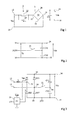
- the figure 1 represents, schematically, an example of conventional architecture of AC-DC converter equipped with a current limiting circuit.
- Two input terminals 12 and 14 are intended to receive an AC voltage Vac, for example, the voltage of the electrical distribution network (for example 230 or 120 volts, 50 or 60 Hz).
- the terminal 12 is connected, via a current limiting circuitry 2, to a first rectifying input terminal 32 of a rectifying bridge 3 (for example, full wave), the second terminal 34
- the rectified outputs 36 and 38 of the bridge are respectively connected to output terminals 16 and 18, providing a DC voltage Vdc.
- a storage and smoothing capacitor C0 connects the terminals 16 and 18.
- the inrush current limiting assembly consists of a resistor 22, connecting the terminals 12 and 32, and an actuatable switch 24 for short-circuiting the resistor. 22. At startup (capacitor C0 discharged), the switch 24 is open and the resistor 22 limits the charging current of the capacitor C0. In steady state, the switch 24 is closed to short-circuit the resistance and limit losses.
- the figure 2 represents, in a schematic way, a modification of the assembly of the figure 1 to make a voltage doubling converter.
- the terminal 34 is connected, via a switch 21, to a midpoint between two capacitive elements C01 and C02 connecting the terminals 16 and 18 (the capacitor C0 can be removed). Assuming that the elements C01 and C02 are of the same capacity, the voltage Vdc between the terminals 16 and 18 corresponds, in steady state, to twice the peak voltage Vac between the terminals 12 and 14.
- the presence of the switch 24 generates losses in steady state.
- this switch can be realized by a triac and the losses are related to the on-state resistance of this triac.
- the figure 3 represents, schematically, an embodiment of AC-DC converter.
- rectifier bridge There is a rectifier bridge whose input terminals 32 and 34 are coupled to first and second terminals 12 and 14 for applying an alternating voltage Vac and whose rectified output terminals 36 and 38 are connected to third and fourth terminals 16 and 18 for supplying a DC voltage Vdc. At least one capacitive element connects terminals 16 and 18 together. In the example of figure 3 an inductive element is interposed between a supply terminal of the voltage Vac (here, terminal 12) and the bridge.
- the rectifier bridge 3 here consists of two thyristor-type controllable rectifying elements Th1 and Th2 connected in a branch of the bridge, that is to say in series between the terminals 36 and 38.
- thyristor Th1 with anode gate
- thyristor Th2 with cathode gate
- terminal 38 to terminal 32 with its anode terminal side 38.
- Two diodes D33 and D35 complete the bridge by respectively connecting terminal 34 to terminal 36 and terminal 38 to terminal 34, the anodes of the diodes D33 and D35 being respectively terminal side 34 and terminal side 38.
- the thyristors Th1 and Th2 are controlled by an electronic circuit, for example a microcontroller 26, responsible for generating control pulses of thyristors Th1 and Th2 and controlling the gates of these thyristors by means of one or two isolated couplers (no represented in figure 3 ), optical, magnetic or capacitive technology.
- the microcontroller 26 receives different setpoints CT or measurements to generate these pulses at the right times depending, among other things, the needs of the load supplied by the converter.
- the figure 4 represents, partially, an embodiment of a control circuit of thyristors Th1 and Th2 of the mounting of the figure 3 .
- Thyristors Th1 and Th2 are chosen so that their control is referenced at the same point.
- thyristor Th1 is an anode gate thyristor. Its control is therefore referenced with respect to terminal 32.
- Thyristor Th2 is a cathode gate thyristor. Its command is referenced with respect to the same terminal 32.
- thyristors Th1 and Th2 are chosen to operate respectively by gate current extraction and trigger current injection.
- a first winding L41 of a transformer 4 receives a pulse command from a microcontroller 26 fed by a DC voltage Vcc.
- the other end of the winding L41 is connected to the midpoint of a series association of two capacitive elements C43 and C44 between the supply terminal Vcc and ground.
- a second winding L42 of the transformer 4 has one end connected to the terminal 32 and its other end coupled to the gates of thyristors Th1 and Th2. This coupling is achieved by means of an optional R45 series resistor and two diodes D46 and D47 respectively connecting the winding L42 (or the resistor R45) to the gates of thyristors Th1 and Th2.
- the anode gate of thyristor Th1 is connected to the anode of diode D46 while the cathode gate of thyristor Th2 is connected to the cathode of diode D47, the cathode of diode D46 and the anode of diode D47 being connected to winding L42 (or resistor R45).
- the circuit of the figure 4 thus, it is possible to inject at the same time a gate current at thyristor Th2, and to extract a gate current from thyristor Th1.
- the two thyristors are therefore controlled each time an alternating pulse (of type + Vcc / 2 -Vcc / 2) is applied to the primary L41 of the transformer 4.
- thyristors Th1 and Th2 are chosen to operate both by current extraction from their trigger.
- Vdd said negative (that is to say, whose high level, VDD, is connected to the terminal 32, itself connected to the terminal 12 of the sector) is sufficient to power the two thyristors Th1 and Th2.
- This same power supply could be used to feed the triggers of triacs whose control reference would be connected to this terminal 32.
- Such triacs would have the utility of controlling AC loads supplied by the voltage Vac.
- cathode gate thyristor function controllable by current extraction.
- a triac in series with a diode can be used to make it unidirectional.
- FIGS. 5 and 6 are schematic sections for the production of thyristors with cathode gate respectively with positive gate current or current injection (the most common case) and with negative gate current or current extraction.
- the thyristor is produced in an N-type substrate 51.
- a P-type layer 52 defines an anode region, the anode electrode A being obtained by a contact resumption metallization 53 of this region 52.
- a box 54 of type P is formed on the front face.
- An N-type cathode region 55 (N1) is formed in this well 54 and a contact recovery metallization 56 of this region 55 defines the cathode electrode K.
- a gate contact 57 is made at the P type box 54.
- the injection of a trigger current initiates the thyristor if it is suitably biased (anode voltage-positive cathode).
- an N-type region 58 (N2) is added under the gate contact 57.
- This region 58 allows priming by a negative gate current (that is to say, flowing from the cathode K to the trigger G) by allowing an injection of electrons into the substrate 51 of the type N which corresponds to the base of the PNP bipolar transistor formed by regions 52-51-54.
- the region 58 may be split at least in two to allow direct contact of the P region (54) on the trigger.
- a “short-circuit hole” makes it possible to improve the immunity to the voltage transients of the thyristor and also allows the control by a positive trigger current (that is to say flowing from trigger G to at cathode K). This variant therefore allows this thyristor to be used at the level of the component Th2 in the circuit of the figure 4 .
- the use of thyristors makes it possible to control the phase angle and thus gradually increase the conduction time of the thyristors in order to ensure a progressive charge of the capacitors. connected between the terminals 36 and 38 and thus limit the inrush current absorbed between the input terminals 12 and 14 when the circuit is energized.
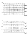
- FIGS. 7A, 7B, 7C and 7D illustrate, by chronograms, the operation of the converter of the figure 3 , in the embodiment where thyristors Th1 and Th2 both operate by current extraction of their trigger in voltage doubler mode (switch 21 closed).
- These figures illustrate the operation at startup of the converter, that is to say as long as the voltage Vdc has not reached its steady state value, approximately twice the peak value of the voltage Vac (about 320 volts).
- the Figure 7A represents examples of the steps of the voltage Vac.
- the Figure 7B illustrates the shape of the current IL in the inductor L.
- the Figure 7C illustrates the steps of the gate voltages V GT thyristors Th1 and Th2 (a peak in two corresponding to each of the thyristors).
- the Figure 7D illustrates the shape of the voltage Vdc obtained.
- FIGS. 8A, 8B, 8C and 8D illustrate, by chronograms, the operation of the converter of the figure 3 in the embodiment where thyristors Th1 and Th2 both operate by current extraction from their trigger, in follower mode (switch 21 open).
- These figures illustrate the operation at startup of the converter, that is to say as long as the voltage Vdc has not reached its steady state value, approximately twice the peak value of the voltage Vac (about 320 volts).
- the figure 8A represents examples of the steps of the voltage Vac.
- the Figure 8B illustrates the shape of the current IL in the inductor L.
- the Figure 8C illustrates the steps of the gate voltages V GT thyristors Th1 and Th2 (a peak in two corresponding to each of the thyristors).
- the figure 8D illustrates the shape of the voltage Vdc obtained.
- the figure 9 represents another embodiment of an AC-DC converter.
- a circuit 9 for generating a voltage VDD2 to be applied to the terminal 32 This voltage VDD2 is generated by a transformer 91 generating, from a first winding L92, two DC voltages VDD1 and VDD2 across two terminals. coupled L93 and L94 windings (the winding L93 being coupled to the winding L92 and the winding L94 being coupled to the winding L93).
- a diode D1 connects the terminal 32 to the winding L92 (terminal-side anode 32) whose other end is connected to the terminal 18 (and therefore the terminal 38) by an electronic control circuit 95 generally incorporating a MOSFET transistor which controls cutting mode the current of winding L92.
- One end of the winding L93 is connected by a diode D96 (anode side winding) to the terminal 32. Its other end is the reference of the voltage VDD2.
- One end of the winding L94 is connected by a diode D97 (anode winding side) to a terminal 98 providing the voltage VDD1.
- the other end of the winding L94 is connected to the terminal 18 and a capacitor C99 connects the terminals 98 to 18.
- a diode D2 connects the terminal 14 to the winding L92 to supply the circuit 95 from a full-wave rectification when Th2 is made conductive by the control circuit 26 of the figure 3 .
- Such an embodiment makes it possible to limit the inrush current if thyristors Th1 and Th2 are controlled in phase angle in order to perform the soft start function.
- a capacitor C0 is furthermore placed in parallel with the series connection of the capacitors C01 and C02.
- the figure 10 illustrates, in a partial diagram, an example of control thyristors Th1 and Th2 by pulses generated by the microcontroller.
- the triggers of thyristors Th1 and Th2 are connected, by resistors R3 and R4, to the collector of a optotransistor of an optocoupler 4 whose emitter is grounded.
- a photodiode of the optocoupler 4 is pulsed by the microcontroller 26.
- the thyristors can be replaced by triacs, each in series with a diode.
- the practical implementation of the embodiments that have been described is within the abilities of those skilled in the art from the functional indications given above.
- the programming of the microcontroller depends on the application and the embodiments described are compatible with the usual applications using a microcontroller or the like to control a converter.
Landscapes
- Engineering & Computer Science (AREA)
- Power Engineering (AREA)
- Rectifiers (AREA)
Applications Claiming Priority (1)
| Application Number | Priority Date | Filing Date | Title |
|---|---|---|---|
| FR1552985A FR3034924A1 (fr) | 2015-04-07 | 2015-04-07 | Convertisseur alternatif-continu a limitation du courant d'appel |
Publications (1)
| Publication Number | Publication Date |
|---|---|
| EP3079246A1 true EP3079246A1 (de) | 2016-10-12 |
Family
ID=53879579
Family Applications (1)
| Application Number | Title | Priority Date | Filing Date |
|---|---|---|---|
| EP15193343.9A Withdrawn EP3079246A1 (de) | 2015-04-07 | 2015-11-06 | Wechselstrom-gleichstromwandler mit begrenzung des einschaltstroms |
Country Status (4)
| Country | Link |
|---|---|
| US (2) | US9755541B2 (de) |
| EP (1) | EP3079246A1 (de) |
| CN (2) | CN205283418U (de) |
| FR (1) | FR3034924A1 (de) |
Cited By (1)
| Publication number | Priority date | Publication date | Assignee | Title |
|---|---|---|---|---|
| CN114553028A (zh) * | 2020-11-26 | 2022-05-27 | 意法半导体(图尔)公司 | 电压转换器 |
Families Citing this family (12)
| Publication number | Priority date | Publication date | Assignee | Title |
|---|---|---|---|---|
| EP2871760B1 (de) * | 2013-11-08 | 2018-03-21 | DET International Holding Limited | Widerstandslose Vorladung |
| FR3034924A1 (fr) * | 2015-04-07 | 2016-10-14 | St Microelectronics Tours Sas | Convertisseur alternatif-continu a limitation du courant d'appel |
| FR3037741A1 (fr) * | 2015-06-22 | 2016-12-23 | St Microelectronics Tours Sas | Convertisseur a circuit correcteur du facteur de puissance |
| FR3068547B1 (fr) * | 2017-06-30 | 2019-08-16 | Stmicroelectronics (Tours) Sas | Convertisseur ac/dc reversible a thyristors |
| FR3068546B1 (fr) * | 2017-06-30 | 2020-12-11 | St Microelectronics Tours Sas | Convertisseur ac/dc reversible a triacs |
| FR3076661A1 (fr) | 2018-01-05 | 2019-07-12 | Stmicroelectronics (Tours) Sas | Triode semiconductrice |
| FR3097386B1 (fr) * | 2019-06-17 | 2021-07-02 | St Microelectronics Ltd | Commande d'un thyristor |
| FR3102897B1 (fr) * | 2019-10-30 | 2021-11-12 | St Microelectronics Tours Sas | Pont redresseur |
| CN111342436B (zh) * | 2020-01-09 | 2021-10-26 | 重庆理工大学 | 一种浪涌电流抑制电路与方法 |
| FR3126823A1 (fr) * | 2021-09-08 | 2023-03-10 | Stmicroelectronics (Tours) Sas | Convertisseur de tension |
| US20250023447A1 (en) * | 2021-11-24 | 2025-01-16 | Aes Global Holdings Pte Ltd. | Power supply full-brick module with internal inrush current limit circuit |
| US12362662B2 (en) | 2023-05-30 | 2025-07-15 | Stmicroelectronics International N.V. | Commutation assistance by controlling the shape of the current wave in a bidirectional totem pole converter |
Citations (3)
| Publication number | Priority date | Publication date | Assignee | Title |
|---|---|---|---|---|
| EP0633652A2 (de) * | 1993-07-09 | 1995-01-11 | Sgs-Thomson Microelectronics Pte Ltd. | Gleichspannungsversorgungsschaltung |
| US5468976A (en) * | 1993-08-27 | 1995-11-21 | Evseev; Yury | Semi conductor rectifying module |
| US20120230075A1 (en) | 2011-03-08 | 2012-09-13 | Lsis Co., Ltd. | Power conversion apparatus and power conversion method thereof |
Family Cites Families (29)
| Publication number | Priority date | Publication date | Assignee | Title |
|---|---|---|---|---|
| SE370297B (de) * | 1973-02-02 | 1974-10-07 | Asea Ab | |
| DE2362375C2 (de) * | 1973-12-12 | 1982-12-16 | Licentia Patent-Verwaltungs-Gmbh, 6000 Frankfurt | Aus einem Wechselstromnetz gespeister steuer- und löschbarer Stromrichter für hohe Gleichstromwerte |
| JPS51127343A (en) * | 1975-04-28 | 1976-11-06 | Hitachi Ltd | Controlling transducer |
| US4075510A (en) * | 1976-09-17 | 1978-02-21 | Pascente Joseph E | Thyristor voltage switching circuits |
| US4314322A (en) * | 1980-03-06 | 1982-02-02 | Reliance Electric Company | Three phase regulated supply with ripple current regulation |
| FR2556521B1 (fr) * | 1983-12-13 | 1986-08-29 | Jeumont Schneider | Dispositif d'alimentation d'une charge notamment un moteur a courant continu pour locomotives ferroviaires du type bi-courant |
| DE3573694D1 (en) * | 1984-06-11 | 1989-11-16 | Toshiba Kk | Power converter for ac load |
| US4837672A (en) | 1988-08-30 | 1989-06-06 | Storage Technology Corporation | Switched mode power supply |
| CN2160168Y (zh) * | 1993-03-10 | 1994-03-30 | 江允良 | 交流电机速度控制器 |
| JP3373349B2 (ja) * | 1995-06-09 | 2003-02-04 | 三菱電機株式会社 | 整流器制御装置 |
| JP3249380B2 (ja) | 1995-06-13 | 2002-01-21 | 株式会社東芝 | 電力変換装置 |
| FR2746981B1 (fr) * | 1996-03-29 | 1998-06-19 | Sgs Thomson Microelectronics | Commande d'un pont mixte au zero de tension |
| US5798520A (en) * | 1996-07-31 | 1998-08-25 | Imec Vzw | Cell for optical-to-electrical signal conversion and amplification, and operation method thereof |
| US5886892A (en) | 1997-12-05 | 1999-03-23 | Hewlett-Packard Company | Power supply with improved inrush circuit for limiting inrush current |
| US6055167A (en) * | 1998-08-10 | 2000-04-25 | Custom Power Systems, Inc. | Pulse width modulated boost converter integrated with power factor correction circuit |
| JP2000233092A (ja) | 1999-02-12 | 2000-08-29 | Juki Corp | ミシンの制御装置 |
| US6608770B2 (en) | 2001-08-31 | 2003-08-19 | Vlt Corporation | Passive control of harmonic current drawn from an AC input by rectification circuitry |
| CN1592067A (zh) * | 2003-08-28 | 2005-03-09 | 松下电器产业株式会社 | 电源装置以及使用该电源装置的空调机 |
| US7078870B2 (en) * | 2003-09-30 | 2006-07-18 | International Rectifier Corporation | Simplified topology for HID lamps |
| US7327587B2 (en) * | 2004-09-30 | 2008-02-05 | General Electric Company | System and method for power conversion |
| KR100703166B1 (ko) | 2005-08-29 | 2007-04-06 | 삼성전자주식회사 | 전원공급장치 및 전원공급방법 |
| DE102008064659B4 (de) * | 2008-07-03 | 2013-05-29 | Fujitsu Technology Solutions Intellectual Property Gmbh | Schaltungsanordnung und Ansteuerschaltung für ein Netzteil, Computernetzteil und Verfahren zum Schalten eines Netzteils |
| JP4642101B2 (ja) * | 2008-09-11 | 2011-03-02 | 三菱電機株式会社 | 交流直流変換装置、圧縮機駆動装置、空気調和機 |
| JP5279796B2 (ja) | 2010-10-29 | 2013-09-04 | 三菱電機株式会社 | 電力変換装置 |
| EP2533409A1 (de) | 2011-06-10 | 2012-12-12 | Siemens Aktiengesellschaft | Frequenzumrichter mit einer Strombegrenzungseinrichtung und Verfahren zum Betreiben desselben |
| CN104270019A (zh) * | 2014-10-11 | 2015-01-07 | 东南大学 | 一种pwm整流器电路拓扑结构 |
| FR3034924A1 (fr) * | 2015-04-07 | 2016-10-14 | St Microelectronics Tours Sas | Convertisseur alternatif-continu a limitation du courant d'appel |
| FR3034926A1 (fr) * | 2015-04-07 | 2016-10-14 | St Microelectronics Tours Sas | Convertisseur de puissance a limitation du courant d'appel |
| FR3037741A1 (fr) * | 2015-06-22 | 2016-12-23 | St Microelectronics Tours Sas | Convertisseur a circuit correcteur du facteur de puissance |
-
2015
- 2015-04-07 FR FR1552985A patent/FR3034924A1/fr active Pending
- 2015-11-06 EP EP15193343.9A patent/EP3079246A1/de not_active Withdrawn
- 2015-11-25 CN CN201520953651.2U patent/CN205283418U/zh not_active Expired - Lifetime
- 2015-11-25 CN CN201510830997.8A patent/CN106059337A/zh active Pending
- 2015-12-02 US US14/956,482 patent/US9755541B2/en active Active
-
2017
- 2017-07-26 US US15/659,822 patent/US10014797B2/en active Active
Patent Citations (3)
| Publication number | Priority date | Publication date | Assignee | Title |
|---|---|---|---|---|
| EP0633652A2 (de) * | 1993-07-09 | 1995-01-11 | Sgs-Thomson Microelectronics Pte Ltd. | Gleichspannungsversorgungsschaltung |
| US5468976A (en) * | 1993-08-27 | 1995-11-21 | Evseev; Yury | Semi conductor rectifying module |
| US20120230075A1 (en) | 2011-03-08 | 2012-09-13 | Lsis Co., Ltd. | Power conversion apparatus and power conversion method thereof |
Non-Patent Citations (3)
| Title |
|---|
| "ComPack Thyristor Module Platform A new Design that reduces Parts and Material Costs with Higher Power Density", 31 December 2013 (2013-12-31), XP055245468, Retrieved from the Internet <URL:http://www.ixys.com/documents/ixys_news2013.pdf> [retrieved on 20160127] * |
| CLAUDE CHEVASSU: "composants de l'électronique de puissance", 1 September 2005 (2005-09-01), XP055604562, Retrieved from the Internet <URL:http://mach.elec.free.fr/divers/polycop_composants_elec_puiss.pdf> [retrieved on 20190711] * |
| TAKANO H ET AL: "COMPARATIVE STUDY OF RESONANT AND NON-RESONANT DC-DC CONVERTER WITHPARASITIC LC COMPONENTS OF HIGH-VOLTAGE TRANSFORMER", CONFERENCE RECORD OF THE 1998 IEEE INDUSTRY APPLICATIONS CONFERENCE. 33RD IAS ANNUAL MEETING. ST. LOUIS, MO, OCT. 12 - 15, 1998; [CONFERENCE RECORD OF THE IEEE INDUSTRY APPLICATIONS CONFERENCE. IAS ANNUAL MEETING], NEW YORK, NY : IEEE, US, 12 October 1998 (1998-10-12), pages 1580 - 1587, XP000876198, ISBN: 978-0-7803-4944-5 * |
Cited By (2)
| Publication number | Priority date | Publication date | Assignee | Title |
|---|---|---|---|---|
| CN114553028A (zh) * | 2020-11-26 | 2022-05-27 | 意法半导体(图尔)公司 | 电压转换器 |
| US12407270B2 (en) | 2020-11-26 | 2025-09-02 | Stmicroelectronics (Tours) Sas | Voltage converter |
Also Published As
| Publication number | Publication date |
|---|---|
| US9755541B2 (en) | 2017-09-05 |
| CN106059337A (zh) | 2016-10-26 |
| US20160301326A1 (en) | 2016-10-13 |
| FR3034924A1 (fr) | 2016-10-14 |
| US10014797B2 (en) | 2018-07-03 |
| CN205283418U (zh) | 2016-06-01 |
| US20170324350A1 (en) | 2017-11-09 |
Similar Documents
| Publication | Publication Date | Title |
|---|---|---|
| EP3079246A1 (de) | Wechselstrom-gleichstromwandler mit begrenzung des einschaltstroms | |
| EP3079251A1 (de) | Leistungswandler mit begrenzung des einschaltstroms | |
| EP3109988A1 (de) | Leistungswandler mit korrekturschaltkreis des leistungsfaktors | |
| EP3422554B1 (de) | Reversibler ac/dc-wandler mit thyristoren | |
| EP3079247B1 (de) | Steuerschaltkreis einer gleichrichterbrücke | |
| EP3422555B1 (de) | Reversibler ac/dc-wandler mit triacs | |
| EP3182571B1 (de) | Gleichrichteranordnung mit thyristoren | |
| EP2770636B1 (de) | Steuervorrichtung, die in einem Stromzuführungssystem mit Partitionierung verwendet wird | |
| EP3754849B1 (de) | Steuerung eines thyristors | |
| FR2988931A1 (fr) | Dispositif de commande employe dans un systeme d'alimentation electrique a decoupage | |
| EP3010133B1 (de) | Anordnung zur kontrollierten gleichrichtung | |
| EP3051681B1 (de) | Begrenzungsschaltkreis für den einschaltstrom | |
| EP3745578B1 (de) | Entladung eines wechselkondensators | |
| EP2320553B1 (de) | Stromumwandlungsvorrichtung und unterbrechungsfreie Stromversorgung, die eine solche Vorrichtung umfasst | |
| FR2727586A1 (fr) | Circuit de commande pour un interrupteur a semi-conducteur | |
| WO2008009538A1 (fr) | Procede et dispositif de regulation d'un onduleur resonant, et onduleur resonant equipe d'un tel dispositif | |
| WO2014091088A1 (fr) | Circuit de comparaison d'une tension a un seuil et conversion d'energie electrique | |
| EP0843412B1 (de) | Anwesenheitsdetektor mit einer stabilisierten Stromquelle | |
| EP3965299B1 (de) | Vorrichtung zur steuerung eines thyristors | |
| EP2015437A2 (de) | Schaltkreis zur Steuerung eines Wechselumschalters | |
| FR3102897A1 (fr) | Pont redresseur | |
| FR2713029A1 (fr) | Dispositif d'alimentation de circuit de commande de composant interrupteur de puissance. | |
| FR3076676A1 (fr) | Commande pour thyristor a gachette d'anode | |
| WO1981001920A1 (fr) | Dispositif de recuperation d'energie pour onduleur | |
| WO1985005512A1 (fr) | Interface de pilotage d'un interrupteur statique electronique a blocage commandable |
Legal Events
| Date | Code | Title | Description |
|---|---|---|---|
| PUAI | Public reference made under article 153(3) epc to a published international application that has entered the european phase |
Free format text: ORIGINAL CODE: 0009012 |
|
| 17P | Request for examination filed |
Effective date: 20151106 |
|
| AK | Designated contracting states |
Kind code of ref document: A1 Designated state(s): AL AT BE BG CH CY CZ DE DK EE ES FI FR GB GR HR HU IE IS IT LI LT LU LV MC MK MT NL NO PL PT RO RS SE SI SK SM TR |
|
| AX | Request for extension of the european patent |
Extension state: BA ME |
|
| 17Q | First examination report despatched |
Effective date: 20190520 |
|
| STAA | Information on the status of an ep patent application or granted ep patent |
Free format text: STATUS: THE APPLICATION IS DEEMED TO BE WITHDRAWN |
|
| 18D | Application deemed to be withdrawn |
Effective date: 20191128 |