EP3081313A1 - Procédé et dispositif de vérification de la constitution de la surface d'un composant, en particulier un composant en fibres de carbone - Google Patents
Procédé et dispositif de vérification de la constitution de la surface d'un composant, en particulier un composant en fibres de carbone Download PDFInfo
- Publication number
- EP3081313A1 EP3081313A1 EP15001052.8A EP15001052A EP3081313A1 EP 3081313 A1 EP3081313 A1 EP 3081313A1 EP 15001052 A EP15001052 A EP 15001052A EP 3081313 A1 EP3081313 A1 EP 3081313A1
- Authority
- EP
- European Patent Office
- Prior art keywords
- component
- areas
- test liquid
- poor
- light source
- Prior art date
- Legal status (The legal status is an assumption and is not a legal conclusion. Google has not performed a legal analysis and makes no representation as to the accuracy of the status listed.)
- Withdrawn
Links
Images
Classifications
-
- G—PHYSICS
- G01—MEASURING; TESTING
- G01N—INVESTIGATING OR ANALYSING MATERIALS BY DETERMINING THEIR CHEMICAL OR PHYSICAL PROPERTIES
- G01N21/00—Investigating or analysing materials by the use of optical means, i.e. using sub-millimetre waves, infrared, visible or ultraviolet light
- G01N21/62—Systems in which the material investigated is excited whereby it emits light or causes a change in wavelength of the incident light
- G01N21/63—Systems in which the material investigated is excited whereby it emits light or causes a change in wavelength of the incident light optically excited
- G01N21/64—Fluorescence; Phosphorescence
-
- G—PHYSICS
- G01—MEASURING; TESTING
- G01N—INVESTIGATING OR ANALYSING MATERIALS BY DETERMINING THEIR CHEMICAL OR PHYSICAL PROPERTIES
- G01N21/00—Investigating or analysing materials by the use of optical means, i.e. using sub-millimetre waves, infrared, visible or ultraviolet light
- G01N21/62—Systems in which the material investigated is excited whereby it emits light or causes a change in wavelength of the incident light
- G01N21/63—Systems in which the material investigated is excited whereby it emits light or causes a change in wavelength of the incident light optically excited
- G01N21/64—Fluorescence; Phosphorescence
- G01N21/645—Specially adapted constructive features of fluorimeters
- G01N21/6456—Spatial resolved fluorescence measurements; Imaging
-
- B—PERFORMING OPERATIONS; TRANSPORTING
- B05—SPRAYING OR ATOMISING IN GENERAL; APPLYING FLUENT MATERIALS TO SURFACES, IN GENERAL
- B05B—SPRAYING APPARATUS; ATOMISING APPARATUS; NOZZLES
- B05B13/00—Machines or plants for applying liquids or other fluent materials to surfaces of objects or other work by spraying, not covered by groups B05B1/00 - B05B11/00
-
- G—PHYSICS
- G01—MEASURING; TESTING
- G01N—INVESTIGATING OR ANALYSING MATERIALS BY DETERMINING THEIR CHEMICAL OR PHYSICAL PROPERTIES
- G01N21/00—Investigating or analysing materials by the use of optical means, i.e. using sub-millimetre waves, infrared, visible or ultraviolet light
- G01N21/84—Systems specially adapted for particular applications
- G01N21/88—Investigating the presence of flaws or contamination
- G01N21/94—Investigating contamination, e.g. dust
-
- G—PHYSICS
- G01—MEASURING; TESTING
- G01N—INVESTIGATING OR ANALYSING MATERIALS BY DETERMINING THEIR CHEMICAL OR PHYSICAL PROPERTIES
- G01N13/00—Investigating surface or boundary effects, e.g. wetting power; Investigating diffusion effects; Analysing materials by determining surface, boundary, or diffusion effects
-
- G—PHYSICS
- G01—MEASURING; TESTING
- G01N—INVESTIGATING OR ANALYSING MATERIALS BY DETERMINING THEIR CHEMICAL OR PHYSICAL PROPERTIES
- G01N21/00—Investigating or analysing materials by the use of optical means, i.e. using sub-millimetre waves, infrared, visible or ultraviolet light
- G01N21/62—Systems in which the material investigated is excited whereby it emits light or causes a change in wavelength of the incident light
- G01N21/63—Systems in which the material investigated is excited whereby it emits light or causes a change in wavelength of the incident light optically excited
- G01N21/64—Fluorescence; Phosphorescence
- G01N21/645—Specially adapted constructive features of fluorimeters
- G01N21/6456—Spatial resolved fluorescence measurements; Imaging
- G01N2021/646—Detecting fluorescent inhomogeneities at a position, e.g. for detecting defects
-
- G—PHYSICS
- G01—MEASURING; TESTING
- G01N—INVESTIGATING OR ANALYSING MATERIALS BY DETERMINING THEIR CHEMICAL OR PHYSICAL PROPERTIES
- G01N21/00—Investigating or analysing materials by the use of optical means, i.e. using sub-millimetre waves, infrared, visible or ultraviolet light
- G01N21/84—Systems specially adapted for particular applications
- G01N21/88—Investigating the presence of flaws or contamination
- G01N21/91—Investigating the presence of flaws or contamination using penetration of dyes, e.g. fluorescent ink
Definitions
- the invention relates to a method for testing the surface quality of a component, in particular a CFRP component, for the detection of a coating or adhesive suitability, in which the surface of the component is wetted with a test liquid.
- the invention also relates to a device for carrying out this method on a component.
- the field of application of the invention extends to the production of components to be coated or adhesively bonded, in which a minimum quality of the surface finish is to be ensured in order to be able to carry out the coating or gluing process without errors.
- adequate adhesion and wetting properties of the corresponding component surfaces are required.
- the properties of these component surfaces are usually already determined in the preceding molding process, such as polymer injection molding, metal die casting or lamination. Because in these shaping processes, the components are often contaminated by release agents based on fluorocarbons, silicones, oils or waxes. Even with mechanical processing through exciting manufacturing processes, contamination of the component surface can occur due to cooling emulsions and cutting oils.
- a spray of water is generated as a test liquid. This is brought into contact with the surface of the component to be tested in order to produce droplets of the spray thereon.
- the drops thus formed are optically detected and determined with regard to the distribution of values of a drop property, for example, volume, surface areas, perimeters and / or shape factors. The determined value distribution is then compared with a reference value distribution to determine the surface condition of the preselected area.
- the object of the present invention is to provide a method and a device for testing the surface condition of a component, in particular a component CFRP component with a structured surface to create, with which the coating and adhesion suitability can be reliably determined in a simple manner.
- the invention includes the procedural teaching that as a test liquid, a fluorescent primer is applied to the test surface of the component, which is then dried on the surface and then irradiated with a light source, so that on the surface areas of poor surface finish optically visible.
- the advantage of the solution according to the invention lies in particular in the fact that the fluorescent primer used as a test liquid on the one hand by fluorescence enables reliable visual recognition of the surface coverage with contaminants, for example with siloxanes; On the other hand, the integrated priming property results in improved coating or adhesive adhesion, resulting in higher aging resistance of the coating.
- the method according to the invention can also be applied to structured surfaces and also reliably covers smaller imperfections.
- the fluorescent primer is sprayed onto the surface.
- this special test liquid can be applied evenly over the areas of the surface to be tested. This can be done either manually or automatically with a sprayer. For the display of bad Adhesive components are also sufficient for a partially mottled order of the special test liquid.
- a radiant heat source should be used in order not to affect the distribution of the test liquid on the surface.
- the dried fluorescent primer should according to another measure improving the invention be irradiated with an ultraviolet light, so-called black light emitting light source.
- UV light so-called black light emitting light source.
- black light emitting light source an ultraviolet light, so-called black light emitting light source.
- UV light makes it easier to recognize the areas of poor surface finish in which contaminants are represented by areas of varying degrees of fluorescence. This means that areas of different contaminations fluoresce to different degrees. Due to the integrated priming property of the test liquid, these areas of poor coating and adhesion suitability are at least partially converted into areas of adequate coating or adhesion suitability. Only with very high levels of contamination would additional surface treatment be required to effect the coating or adhesion suitability.
- the inventive method also serves to save any intermediate process steps.
- the method according to the invention is preferably carried out with a device which has a spray unit for wetting the surface of the component with the special test fluid and an additional light source for illuminating the treated surface with ultraviolet light.
- a heat source for faster drying of the treated surface.
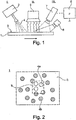
- FIG. 1 There is a device for testing the surface condition of a component 1, which is exemplarily a CFRP component, consisting essentially of a spray unit 2 for wetting a surface 3 of the component 1 with a test liquid 4.
- the test liquid 4 is a fluorescent primer which has both luminous properties as well as adhesion promoting properties.
- the test liquid 4 applied to the surface 3 of the component 1 by the spray unit 2 as a thin film is then dried on the surface 3 by a radiant heat source 5 in the form of a heating screen. If, subsequently, the surface 3 is irradiated with a light source 6 directed thereon, then areas which are not recognizable further here are optically visible with a lack of surface finish.
- the light source 6 emits ultraviolet light, so that the optical visibility by fluorescence differences of the primer on the surface 3 emerges particularly strong.
- an optical camera unit 7 is also provided within the scope of the exemplary apparatus, which detects the areas with a poor surface finish on the surface 3 of the component 1 as image signals.
- a downstream electronic evaluation unit 8 performs a pattern comparison of the captured image signals with stored image patterns in order to identify and output significant areas with a poor surface finish.
- the component 3 runs in the direction of the arrow through the device, in which the test liquid 4 is first applied to the surface 3 of the component 1 at a station I.
- the sprayed-on fluorescent test liquid 4 is dried by a radiant heat source 5 directed onto the surface 3.
- a third station III Be detected and evaluated with the help of an ultraviolet light source 6 in combination with an optical camera unit 7 areas with poor surface finish of the component 1.
- FIG. 4 illustrates an exemplary image of a portion of a surface 3 of the component 1.
- an area 9 of imperfect surface condition which has a poor adhesive property due to contamination with, for example, silicones (within a dashed line).
- This region 9 can be recognized by the droplets of dried test liquid 4a which are present therein which have a very lower fluorescence than drops of dried test liquid 4b which are adjacent to the region 9 and have a comparatively high fluorescence.
- primer property impurities can be at least partially rendered harmless and a improved adhesion for subsequent coating with a topcoat or adhesion to another component is made without requiring a cleaning step.
- the test method results in further and larger areas of a comparatively poorer surface finish, it may be decided as a result of the test method to first supply the component 3 to a cleaning of the surface before further surface-sensitive processing takes place.
Landscapes
- Health & Medical Sciences (AREA)
- Biochemistry (AREA)
- Physics & Mathematics (AREA)
- Life Sciences & Earth Sciences (AREA)
- Chemical & Material Sciences (AREA)
- Analytical Chemistry (AREA)
- General Health & Medical Sciences (AREA)
- General Physics & Mathematics (AREA)
- Immunology (AREA)
- Pathology (AREA)
- Nuclear Medicine, Radiotherapy & Molecular Imaging (AREA)
- Investigating Materials By The Use Of Optical Means Adapted For Particular Applications (AREA)
- Investigating, Analyzing Materials By Fluorescence Or Luminescence (AREA)
Priority Applications (2)
| Application Number | Priority Date | Filing Date | Title |
|---|---|---|---|
| EP15001052.8A EP3081313A1 (fr) | 2015-04-13 | 2015-04-13 | Procédé et dispositif de vérification de la constitution de la surface d'un composant, en particulier un composant en fibres de carbone |
| US15/097,561 US20160299074A1 (en) | 2015-04-13 | 2016-04-13 | Method and device for testing the surface quality of a component in particular of a cfrp component |
Applications Claiming Priority (1)
| Application Number | Priority Date | Filing Date | Title |
|---|---|---|---|
| EP15001052.8A EP3081313A1 (fr) | 2015-04-13 | 2015-04-13 | Procédé et dispositif de vérification de la constitution de la surface d'un composant, en particulier un composant en fibres de carbone |
Publications (1)
| Publication Number | Publication Date |
|---|---|
| EP3081313A1 true EP3081313A1 (fr) | 2016-10-19 |
Family
ID=52874922
Family Applications (1)
| Application Number | Title | Priority Date | Filing Date |
|---|---|---|---|
| EP15001052.8A Withdrawn EP3081313A1 (fr) | 2015-04-13 | 2015-04-13 | Procédé et dispositif de vérification de la constitution de la surface d'un composant, en particulier un composant en fibres de carbone |
Country Status (2)
| Country | Link |
|---|---|
| US (1) | US20160299074A1 (fr) |
| EP (1) | EP3081313A1 (fr) |
Cited By (2)
| Publication number | Priority date | Publication date | Assignee | Title |
|---|---|---|---|---|
| DE102019211080A1 (de) * | 2019-07-25 | 2021-01-28 | Airbus Defence and Space GmbH | Verfahren zur Bearbeitung einer Oberfläche eines Faserverbundbauteils und Verfahren zum Verbinden eines Faserverbundbauteils mit einer Zusatzstruktur |
| DE102019132585A1 (de) * | 2019-12-02 | 2021-06-02 | Schaeffler Technologies AG & Co. KG | Prüfsystem zur optischen Oberflächenprüfung eines Prüfkörpers |
Families Citing this family (1)
| Publication number | Priority date | Publication date | Assignee | Title |
|---|---|---|---|---|
| JP7746057B2 (ja) * | 2021-07-28 | 2025-09-30 | エスケー化研株式会社 | 被膜試験装置、被膜試験方法、被膜試験確認方法 |
Citations (7)
| Publication number | Priority date | Publication date | Assignee | Title |
|---|---|---|---|---|
| US3995157A (en) * | 1975-02-18 | 1976-11-30 | General Electric Company | Surface flaw detection |
| US4327155A (en) * | 1980-12-29 | 1982-04-27 | General Electric Company | Coated metal structures and method for making |
| JPH10235267A (ja) * | 1997-02-25 | 1998-09-08 | Ngk Insulators Ltd | プライマー塗布不良検査方法及びそれに用いる検査装置 |
| WO2002071045A2 (fr) * | 2001-01-22 | 2002-09-12 | General Electric Company | Procede de determination de defauts structurels de revetements |
| DE102005027106B3 (de) | 2005-06-10 | 2007-01-04 | Fraunhofer-Gesellschaft zur Förderung der angewandten Forschung e.V. | Prüfverfahren und Prüfvorrichtung |
| US20100260926A1 (en) * | 2009-04-10 | 2010-10-14 | The Penn State Research Foundation | Interactive coatings, surfaces & materials |
| DE102013001600A1 (de) * | 2013-01-30 | 2014-07-31 | Balluff STM GmbH | Prüfverfahren und -Vorrichtung für Oberflächen |
Family Cites Families (6)
| Publication number | Priority date | Publication date | Assignee | Title |
|---|---|---|---|---|
| AU2007223505A1 (en) * | 2006-03-08 | 2007-09-13 | Toray Industries, Inc. | Process for producing fiber-reinforced resin |
| US20080019787A1 (en) * | 2006-07-24 | 2008-01-24 | Karthikeyan Sampath | Drill for machining fiber reinforced composite material |
| KR101609396B1 (ko) * | 2007-12-17 | 2016-04-05 | 라이프 테크놀로지스 코포레이션 | 무기 코팅된 중합체 표면에서 결함을 검출하는 방법 |
| US20140366918A1 (en) * | 2012-01-25 | 2014-12-18 | Diversey, Inc. | Compositions and methods for cleaning management |
| US9671386B2 (en) * | 2013-05-01 | 2017-06-06 | University Of Washington Through Its Center For Commercialization | Detection of thermal damage of composites using molecular probes |
| US10126271B2 (en) * | 2015-09-15 | 2018-11-13 | NLA Diagnostics LLC | Apparatus and method for non-destructive testing of materials |
-
2015
- 2015-04-13 EP EP15001052.8A patent/EP3081313A1/fr not_active Withdrawn
-
2016
- 2016-04-13 US US15/097,561 patent/US20160299074A1/en not_active Abandoned
Patent Citations (7)
| Publication number | Priority date | Publication date | Assignee | Title |
|---|---|---|---|---|
| US3995157A (en) * | 1975-02-18 | 1976-11-30 | General Electric Company | Surface flaw detection |
| US4327155A (en) * | 1980-12-29 | 1982-04-27 | General Electric Company | Coated metal structures and method for making |
| JPH10235267A (ja) * | 1997-02-25 | 1998-09-08 | Ngk Insulators Ltd | プライマー塗布不良検査方法及びそれに用いる検査装置 |
| WO2002071045A2 (fr) * | 2001-01-22 | 2002-09-12 | General Electric Company | Procede de determination de defauts structurels de revetements |
| DE102005027106B3 (de) | 2005-06-10 | 2007-01-04 | Fraunhofer-Gesellschaft zur Förderung der angewandten Forschung e.V. | Prüfverfahren und Prüfvorrichtung |
| US20100260926A1 (en) * | 2009-04-10 | 2010-10-14 | The Penn State Research Foundation | Interactive coatings, surfaces & materials |
| DE102013001600A1 (de) * | 2013-01-30 | 2014-07-31 | Balluff STM GmbH | Prüfverfahren und -Vorrichtung für Oberflächen |
Cited By (4)
| Publication number | Priority date | Publication date | Assignee | Title |
|---|---|---|---|---|
| DE102019211080A1 (de) * | 2019-07-25 | 2021-01-28 | Airbus Defence and Space GmbH | Verfahren zur Bearbeitung einer Oberfläche eines Faserverbundbauteils und Verfahren zum Verbinden eines Faserverbundbauteils mit einer Zusatzstruktur |
| DE102019211080B4 (de) | 2019-07-25 | 2022-08-04 | Airbus Defence and Space GmbH | Verfahren zur Bearbeitung einer Oberfläche eines Faserverbundbauteils und Verfahren zum Verbinden eines Faserverbundbauteils mit einer Zusatzstruktur |
| DE102019132585A1 (de) * | 2019-12-02 | 2021-06-02 | Schaeffler Technologies AG & Co. KG | Prüfsystem zur optischen Oberflächenprüfung eines Prüfkörpers |
| DE102019132585B4 (de) | 2019-12-02 | 2022-06-09 | Schaeffler Technologies AG & Co. KG | Prüfsystem zur optischen Oberflächenprüfung eines Prüfkörpers |
Also Published As
| Publication number | Publication date |
|---|---|
| US20160299074A1 (en) | 2016-10-13 |
Similar Documents
| Publication | Publication Date | Title |
|---|---|---|
| EP3163293B1 (fr) | Procédé de détection de résidus de surface sur des composants à l'aide du rayonnement uv | |
| DE102012200614B4 (de) | Reinigungsanlage für Werkstücke mit Betriebszustands-Überwachung | |
| DE102016114465B4 (de) | Vorrichtung und Verfahren zur Legierungsanalyse von Schrottfragmenten aus Metall | |
| EP2824447B1 (fr) | Procédé d'examen non destructif de surfaces de pièces usinées | |
| EP1979109B1 (fr) | Dispositif et procede d'usinage final d'un outil de formage de piece en tole pour carrosserie | |
| EP3081313A1 (fr) | Procédé et dispositif de vérification de la constitution de la surface d'un composant, en particulier un composant en fibres de carbone | |
| DE102017208103A1 (de) | Verfahren zur automatischen Entfernung von Fremdkörpern aus einer flüssigen Beschichtung eines Substrats | |
| DE102013021371A1 (de) | Verfahren und Vorrichtung zur Herstellung von Formteilen in einer Pressenlinie | |
| DE102012200767B4 (de) | Verfahren zur zerstörungsfreien Prüfung von Werkstückoberflächen | |
| DE102017208102A1 (de) | Verfahren zur vollautomatischen Korrektur von Beschichtungsfehlern | |
| DE102008022649A1 (de) | Verfahren und Vorrichtung zur Vorbereitung von Oberflächen kohlestofffaserverstärkter Kunststoffe | |
| DE102016116201B4 (de) | Verfahren zum Auftragen von Pastenmaterial auf ein Substrat und zum ergänzenden Auftragen von Pastenmaterial auf ein Pastendepot des Substrats, Steuergerät, Computerprogrammprodukt und Siebdrucker | |
| DE102005040190A1 (de) | Vorrichtung und Verfahren zur Überprüfung von Lackmaterialien auf ihre Qualität | |
| WO2015197868A1 (fr) | Dispositif et procédé de contrôle d'une qualité de surface | |
| EP1989010A1 (fr) | Procede pour enfoncer des outils de presse en utilisant une couleur pour lavis | |
| DE102024206123B4 (de) | Verfahren und Prüfsystem zum Detektieren von Pseudodefektstellen an einer Sichtoberfläche | |
| DE102014005546B4 (de) | Verfahren und Vorrichtung für die Reinigungsvalidierung | |
| DE102023002730B4 (de) | Vorrichtung und Verfahren zur Qualitätssicherung bei Oberflächenbehandlungen mittels eines Laserstrahls sowie Verwendung der selbigen | |
| EP1270095B1 (fr) | Procédé de surveillance d'un prétraitement avec un jet de plasma | |
| DE102024110375A1 (de) | Verfahren und Vorrichtung zur Detektion einer gasförmigen Emission aus einer Oberfläche | |
| DE102017100375A1 (de) | Innengewindeprüfsystem, Verfahren zur Innengewindeprüfung sowie Computerprogramm | |
| DE102015215348B4 (de) | Verfahren zum Verbinden eines Bauteils mit mindestens zwei Clipelementen | |
| DE102017003792A1 (de) | Analyseverfahren zur Ermittlung von lackbenetzungsstörenden Substanzen in Wasser zum Einsatz bei der Kraftwagenlackierung | |
| DE102022204371A1 (de) | Vorrichtung zur Prüfung des Aushärtungszustandes von KTL beschichteten Bauteilen | |
| DE102010043653A1 (de) | Verfahren und Vorrichtung zum Erkennen einer Restflüssigkeit in Behältern |
Legal Events
| Date | Code | Title | Description |
|---|---|---|---|
| PUAI | Public reference made under article 153(3) epc to a published international application that has entered the european phase |
Free format text: ORIGINAL CODE: 0009012 |
|
| AK | Designated contracting states |
Kind code of ref document: A1 Designated state(s): AL AT BE BG CH CY CZ DE DK EE ES FI FR GB GR HR HU IE IS IT LI LT LU LV MC MK MT NL NO PL PT RO RS SE SI SK SM TR |
|
| AX | Request for extension of the european patent |
Extension state: BA ME |
|
| STAA | Information on the status of an ep patent application or granted ep patent |
Free format text: STATUS: REQUEST FOR EXAMINATION WAS MADE |
|
| 17P | Request for examination filed |
Effective date: 20170307 |
|
| RBV | Designated contracting states (corrected) |
Designated state(s): AL AT BE BG CH CY CZ DE DK EE ES FI FR GB GR HR HU IE IS IT LI LT LU LV MC MK MT NL NO PL PT RO RS SE SI SK SM TR |
|
| STAA | Information on the status of an ep patent application or granted ep patent |
Free format text: STATUS: THE APPLICATION IS DEEMED TO BE WITHDRAWN |
|
| 18D | Application deemed to be withdrawn |
Effective date: 20181101 |