EP3081736A1 - Joint de blocage pour échelles repliables et d'autres structures - Google Patents
Joint de blocage pour échelles repliables et d'autres structures Download PDFInfo
- Publication number
- EP3081736A1 EP3081736A1 EP16170957.1A EP16170957A EP3081736A1 EP 3081736 A1 EP3081736 A1 EP 3081736A1 EP 16170957 A EP16170957 A EP 16170957A EP 3081736 A1 EP3081736 A1 EP 3081736A1
- Authority
- EP
- European Patent Office
- Prior art keywords
- ladder
- cam
- ladder section
- cam element
- rail
- Prior art date
- Legal status (The legal status is an assumption and is not a legal conclusion. Google has not performed a legal analysis and makes no representation as to the accuracy of the status listed.)
- Granted
Links
Images


Classifications
-
- E—FIXED CONSTRUCTIONS
- E06—DOORS, WINDOWS, SHUTTERS, OR ROLLER BLINDS IN GENERAL; LADDERS
- E06C—LADDERS
- E06C1/00—Ladders in general
- E06C1/02—Ladders in general with rigid longitudinal member or members
- E06C1/38—Special constructions of ladders, e.g. ladders with more or less than two longitudinal members, ladders with movable rungs or other treads, longitudinally-foldable ladders
- E06C1/383—Foldable ladders in which the longitudinal members are brought together on folding
-
- E—FIXED CONSTRUCTIONS
- E06—DOORS, WINDOWS, SHUTTERS, OR ROLLER BLINDS IN GENERAL; LADDERS
- E06C—LADDERS
- E06C1/00—Ladders in general
- E06C1/02—Ladders in general with rigid longitudinal member or members
- E06C1/04—Ladders for resting against objects, e.g. walls poles, trees
- E06C1/08—Ladders for resting against objects, e.g. walls poles, trees multi-part
- E06C1/10—Sections fitted end to end
-
- E—FIXED CONSTRUCTIONS
- E06—DOORS, WINDOWS, SHUTTERS, OR ROLLER BLINDS IN GENERAL; LADDERS
- E06C—LADDERS
- E06C1/00—Ladders in general
- E06C1/02—Ladders in general with rigid longitudinal member or members
- E06C1/32—Ladders with a strut which is formed as a ladder and can be secured in line with the ladder
-
- E—FIXED CONSTRUCTIONS
- E06—DOORS, WINDOWS, SHUTTERS, OR ROLLER BLINDS IN GENERAL; LADDERS
- E06C—LADDERS
- E06C1/00—Ladders in general
- E06C1/52—Ladders in general with non-rigid longitudinal members
-
- E—FIXED CONSTRUCTIONS
- E06—DOORS, WINDOWS, SHUTTERS, OR ROLLER BLINDS IN GENERAL; LADDERS
- E06C—LADDERS
- E06C7/00—Component parts, supporting parts, or accessories
- E06C7/08—Special construction of longitudinal members, or rungs or other treads
- E06C7/082—Connections between rungs or treads and longitudinal members
- E06C7/087—Connections between rungs or treads and longitudinal members with a connecting piece installed around the rung
-
- E—FIXED CONSTRUCTIONS
- E06—DOORS, WINDOWS, SHUTTERS, OR ROLLER BLINDS IN GENERAL; LADDERS
- E06C—LADDERS
- E06C7/00—Component parts, supporting parts, or accessories
- E06C7/50—Joints or other connecting parts
Definitions
- the present invention relates to mechanisms for locking separate members together such that they form a single rigid member. More particularly, the invention relates to a mechanism that physically locks a rotating joint such that the members comprising the joint become a single rigid member suitable for use in stiff structures such as ladders which can collapsed and deployed.
- Ladders are a universal tool for gaining access to otherwise unreachable places.
- ladders typically being configured as long, rigid structures make them inherently cumbersome to transport and store.
- a ladder having a first ladder section and a second ladder section, with the ladder sections having connecting ends.
- a female hinge element is provided on a first one of the first and second ladder section connecting ends and has an opening with a cam surface.
- a male hinge element is provided on a second one of the first and second ladder section connecting ends and has a transverse connector having a cam follower, the transverse connecting element extending into the opening in the female hinge element such that the cam follower contacts the cam surface.
- the cam surface is an internal cam surface.
- the cam surface can be provided on a cam element that moves in a plane that is parallel to a major surface of a rail with which the cam element is associated.
- the cam surface can be arranged so that the hinge can be moved to a disassembly position where the male and female hinge elements can be assembled or disassembled.
- Differing embodiments of the invention can provide a number of features and advantages, including the enumerated objectives below which should be seen as optional, but may be found in various embodiments or implementations of the invention in any combination or sub-combination.
- One object of the present invention can be to provide a mechanism for locking together two rigid members which solves one or more of the problems associated with the conventional methods and techniques described above.
- Another object of the present invention can be to provide a mechanism for locking together two rigid members which can be manufactured at reasonable costs.
- the invention provides a rigid structure, in particular a ladder, having rotating hinges that allow the ladder to fold up and/or be disassembled and assembled.
- the hinge or hinges can be provided between ladder sections with one ladder section having a male hinge element, and another having a female hinge element.
- a cam element provided with the female hinge element can be moved between an unlocked position in which the ladder sections can rotate with respect to each other, and a locked position in which the structure is rigid.
- FIGs 1A and 1B illustrate a rigid member 100 of the invention, in this case, a ladder 100.
- the ladder 100 is illustrated as three separate parts (first ladder section 102, second ladder section 112, and third ladder section 122) in Figure 1A , and assembled in Figure 1B . While the embodiment of these Figures shows three ladder sections, two ladder sections or more than three ladder sections may be employed in keeping with the invention.
- a first ladder section 102 has right and left rails 104, 106, as well as top and bottom rungs 108, 110. Each of the rungs extends across from one rail to the other, in this case with each rung being perpendicular to each rail. While many ladders have two rails, it should be understood that the invention can be applied with a rigid member having at least one rail, and possibly having more than two rails. Configurations other than perpendicular could also be provided. Further, while the illustrated ladder section 102 has two rungs - other ladder sections may have zero, one, or more than two rungs. First ladder section 102 also has a connecting end 130, which may be connected to additional ladder sections.
- first ladder section has two identical connecting ends, one at the top and one at the bottom, but only one connecting end 130 is used in the Figure.
- the first ladder section On the connecting end 130, the first ladder section has a male hinge element 134.
- the first ladder section has four such male hinge elements, the details of which will be described further below.
- a second ladder section 112 is also illustrated in Figures 1A and 1B .
- This section consists of two rails - right and left rails 114, 116. More or fewer rails may be provided and the second ladder section might also have one or more rungs in some embodiments.
- the second ladder section also has a connecting end 132 having a female hinge element 136. As illustrated, the second ladder section includes two connecting ends, both of which are used in the exemplary embodiment, and 4 female hinge elements - one each on each connecting end of each rail in the section.
- a third ladder section 122 is also illustrated in Figures 1A and 1B .
- the third ladder section 122 includes right and left rails 124 and 126 with top and bottom rungs 128, 140 extending perpendicularly between the two rails.
- other configurations of ladder section may be used within the spirit of the invention.
- the ladder sections 102, 112, 122 are assembled to create the ladder assembly of Figure 1B .
- the rails of the first and third ladder sections are "inside” rails, while the rails of the second ladder section are “outside” rails in the sense that when the hinges are assembled, the second ladder section rails are place laterally outside with respect to the first and third ladder assembly rails.
- a portion of the rungs in the first and third ladder assemblies may extend through the "inner" rails to become the male hinge portions.
- the female hinge elements of the "outer” rails can then slide over the male hinge portions to complete the assembly.
- the hinges and locking features can be arranged so that the ladder sections are not locked in a perfectly straight line, but rather in a slight arc that makes the ladder stronger and more stable.
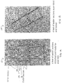
- FIGs 2A and 2B illustrate a ten foot ladder 200 built using four ladder sections 202 having two rails and two rungs (in this case, each of these ladder sections is substantially identical to the first or third ladder sections above) and three ladder sections 204 having only two rails (the "outer" rails in the figures, and these are substantially identical to the second ladder section above).
- the ladder 200 is folded up about its hinges so that in the X and Y dimensions, the ladder assembly is the same size as a single first ladder section 102/202.
- the ladder 200 is unfolded about its hinges and locked into its configuration for use as a ladder.
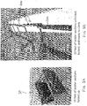
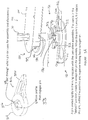
- FIG. 3A illustrated an exploded view of a hinge that can be used with the invention.
- the figure shows right rail 104 and bottom rung 110 of the connecting end 130 of first ladder section 104, as well as the right rail 114 of the connecting end 132 of second ladder section 112.
- Male hinge element 134 is a transverse connecting element extending from rung 110 through rail 104, and includes a pin 142 extending through the male hinge element transversely to act as a cam follower.
- the pin 302 can extend outward from both of opposed sides of the male hinge element.
- the male hinge element 134 can extend into female hinge element 136 in rail 114. In this way, male hinge element 134 can act as an axle about which the second ladder section 112 can rotate about the first ladder section 102.
- the rotating cam element 302 is illustrated in isolation in Figure 3B .
- the rotating cam element 302 includes a body 304 and a handle 306 that can be used to rotate the body.
- the body 304 includes a central opening 316 for receiving the male hinge element 134.
- the opening 316 can include slots 308 that allow the pin 142 (or cam follower) to pass in and out when the cam is rotated to an assembly or disassembly position.
- FIG. 3A Such a position is illustrated in Figure 3A where the slots 308 in the rotating cam element 302 are aligned with similar slots in the opening in rail 114, and further the pin 142 on male hinge element 134 is aligned with slots 308 so that male hinge element can slide into (or out of) the female hinge element in this orientation.
- a cam profile 310 is provided internally along the opening 316 in the rotating cam element 302.
- an internal cam surface or profile refers to a cam surface that is provided within the outer perimeter of the element on which it is located.
- An internal cam surface does not refer to rotating cam elements that use their outer perimeter as the cam surface when they rotate about an axis that is transverse to the direction of the camming motion.
- This rotation results in relative movement between the ladder sections in a direction that is transverse to a plane parallel to a major surface of rail 114, which, in the illustrated embodiment, is also transverse to a plane parallel to a major surface of rail 104 and along the longitudinal axis of rung 110.
- rotating the rotating cam element 302 to an unlocked position allows the rails 104, 114 to move apart, which allows them to rotate with respect to each other.
- Rotating the rotating cam element 302 to a locked position pulls the rails 104, 114 together, causing locking features on the rails to engage each other and prevent relative rotation between the rails.
- outer rail 114 is provided with positive locking features 312, while inner rail 104 includes corresponding negative locking features 314.
- inner rail 104 includes corresponding negative locking features 314.
- positive locking features 312 are provided in three different shapes (as are the complementary negative locking features 314). This feature can be useful in that it allows the ladder sections to rotate freely with respect to each other without risk of the locking features engaging until the ladder sections reach the desired locking position - for a ladder, this will generally be the extended position in which the ladder can be climbed.
- Other configurations of locking features can be provided, however, it may be preferred to provide at least one locking feature that is differentiated in shape from any other locking features so that the hinge can be locked in only one position.
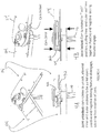
- Figures 4A and 4B show rails 104 and 114 in unlocked and locked conditions respectively, in both isometric and side views.
- the rotating cam element 302 is in the unlocked position, the positive locking features 312 have not engaged with the negative locking features 314, and the ladder sections may rotate freely with respect to each other.
- the rotating cam element 302 has been rotated to the locked position, and it has drawn the rails 104 and 114 together to engage the locking features. In this position, the ladder sections are locked and no relative rotation is possible.
- Figure 4C shows positive 312 and negative 314 locking features coming together under the cam force to lock the relative positions of rails 104, 114.
- the locking features provide zero or minimum backlash when engaging.
- both the positive 312 and negative 314 locking features illustrated are tapered so as to lock the joint with zero backlash when pressed together by the cam.
- FIGS 5A and 5B show a side view with the direction of assembly of the ladder sections illustrated.
- This arrangement includes a ladder section having a rail 502, rung 526, and male hinge element 506.
- Another ladder section includes rail 504 and female hinge element 510.
- a rotating cam element 512 is provided as part of the female hinge element and including a handle 524 and body 522.
- the body 522 defines a central opening having slots 514 to accept the male hinge element 506 having a transverse pin or cam follower 508.
- An internal cam profile 516 is provided on the body 522 to interact with cam follower 508.
- Positive 518 and negative 520 locking features are provided on the rails such that the hinge can be locked into position only in an extended-ladder orientation.
- Figure 5B shows a side view with the direction of assembly of the ladder sections illustrated.
- Figures 5C and 5D illustrate the elements of Figures 5A and 5B where the ladder sections have been assembled and the cam element 512 has been rotated to an unlocked position; the views are isometric and side respectively. In this position, the ladder sections are free to rotate with respect to each other, however, the ladder sections cannot be disassembled.
- the cam follower 508 is resting at the lowest spot on the cam profile 516, allowing the maximum distance between rail 502 and 504 so that the positive 518 and negative 520 locking features are not engaged.
- Figures 5E and 5F illustrate the elements of Figures 5A and 5B where the ladder sections have been assembled and the cam element 512 has been rotated to a locked position; the views are isometric and side respectively. In this position, the ladder sections may not rotate with respect to each other.
- the cam follower 508 is resting at the highest spot on the cam profile 516, pushing the relative elements to a minimum distance between rail 502 and 504 so that the positive 518 and negative 520 locking features engaged to lock the orientation of the ladder.
- Figure 5G provides an isometric view of rotating cam element 512.
- the cam profile 516 is clearly visible and the lowest cam position 532, corresponding to the unlocked position, and the highest cam position 534, corresponding to the locked position can readily be seen.
- Figure 6 provides an alternative sliding cam element 602.
- This cam element has a body 604 and a handle 606.
- the body has a cam profile 608.
- the cam profile 608 is internal as it is within the perimeter of the body 608.
- the profile includes a lowest point 610, which corresponds to the unlocked position, and a highest point 612, which corresponds to the locked position.
- This cam element can, for example, slide along rail 504 underneath pin 508 so that pushing the cam element 602 in locks the relative positions of the ladder sections, while pulling the cam element 602 out allows the ladder sections to rotate relative to each other, and removing the cam element 602 allows the ladder sections to be disassembled.
- Figure 7 provides another alternative cam element 702 having a body 704 and a handle 706.
- the body in this embodiment, the body "hooks” the pin 508 and rotates about it.
- the cam profile 708 in this embodiment is provided on the outside of the body and is thus external.
- the minimum camming or “unlocked” position of the cam profile is illustrated at 712, while the maximum camming or locked position of the cam profile is illustrated at 710.
- This cam element could be flipped over, "hooked” on the pin 508 so that the cam element could rotate about the pin, and then the cam element could be rotated about the pin with the cam profile sliding against rail 504 until the handle rests up against rail 504 in order to lock the relative positions of the ladder sections.
Landscapes
- Engineering & Computer Science (AREA)
- Mechanical Engineering (AREA)
- Ladders (AREA)
Applications Claiming Priority (3)
| Application Number | Priority Date | Filing Date | Title |
|---|---|---|---|
| US201161522924P | 2011-08-12 | 2011-08-12 | |
| EP12823792.2A EP2742200B1 (fr) | 2011-08-12 | 2012-08-13 | Joint de verrouillage pour échelles pliables et autres structures |
| PCT/US2012/050548 WO2013025593A1 (fr) | 2011-08-12 | 2012-08-13 | Joint de verrouillage pour échelles pliables et autres structures |
Related Parent Applications (2)
| Application Number | Title | Priority Date | Filing Date |
|---|---|---|---|
| EP12823792.2A Division EP2742200B1 (fr) | 2011-08-12 | 2012-08-13 | Joint de verrouillage pour échelles pliables et autres structures |
| EP12823792.2A Division-Into EP2742200B1 (fr) | 2011-08-12 | 2012-08-13 | Joint de verrouillage pour échelles pliables et autres structures |
Publications (2)
| Publication Number | Publication Date |
|---|---|
| EP3081736A1 true EP3081736A1 (fr) | 2016-10-19 |
| EP3081736B1 EP3081736B1 (fr) | 2019-07-10 |
Family
ID=47676824
Family Applications (2)
| Application Number | Title | Priority Date | Filing Date |
|---|---|---|---|
| EP16170957.1A Active EP3081736B1 (fr) | 2011-08-12 | 2012-08-13 | Joint de blocage pour échelles repliables |
| EP12823792.2A Active EP2742200B1 (fr) | 2011-08-12 | 2012-08-13 | Joint de verrouillage pour échelles pliables et autres structures |
Family Applications After (1)
| Application Number | Title | Priority Date | Filing Date |
|---|---|---|---|
| EP12823792.2A Active EP2742200B1 (fr) | 2011-08-12 | 2012-08-13 | Joint de verrouillage pour échelles pliables et autres structures |
Country Status (5)
| Country | Link |
|---|---|
| US (2) | US9222307B2 (fr) |
| EP (2) | EP3081736B1 (fr) |
| AU (1) | AU2012295203B2 (fr) |
| CA (1) | CA2844760C (fr) |
| WO (1) | WO2013025593A1 (fr) |
Families Citing this family (13)
| Publication number | Priority date | Publication date | Assignee | Title |
|---|---|---|---|---|
| EP3081736B1 (fr) | 2011-08-12 | 2019-07-10 | Atlas Devices LLC | Joint de blocage pour échelles repliables |
| WO2013057342A1 (fr) * | 2011-10-17 | 2013-04-25 | Ildefonso Aral Diaz | Dispositif de gymnastique |
| CN103127628A (zh) * | 2013-03-12 | 2013-06-05 | 侯世玲 | 多功能可折叠救援器 |
| US9512675B1 (en) * | 2014-06-02 | 2016-12-06 | Curtis D. Fast | Leveling hunting ladder |
| US10017988B2 (en) * | 2014-11-26 | 2018-07-10 | Aims International | Foldable walkway |
| CN109154172B (zh) * | 2016-06-14 | 2021-03-09 | 伟英企业有限公司 | 梯子、梯子铰链和相关方法 |
| AU2017320333B2 (en) * | 2016-08-31 | 2023-03-16 | Justoy Pty Limited | Access device |
| DE102017000341A1 (de) * | 2017-01-16 | 2018-07-19 | Geda-Dechentreiter Gmbh & Co. Kg | Leiterverbinder und Anordnung mit einem Leiterverbinder |
| US20200256125A1 (en) * | 2019-02-13 | 2020-08-13 | Ross Hoffmann | Rescue ladder attachment |
| US11034420B2 (en) * | 2019-02-13 | 2021-06-15 | Ross Hoffmann | Rescue ladder attachment |
| US20200370372A1 (en) * | 2019-02-13 | 2020-11-26 | Ross Hoffmann | Rescue ladder attachment |
| USD966556S1 (en) | 2019-12-13 | 2022-10-11 | Murphy Ladder Llc | Ladder |
| USD1072390S1 (en) * | 2023-12-08 | 2025-04-22 | Changzhou Canbo Travel Products Co., Ltd. | Pet climbing ladder |
Citations (3)
| Publication number | Priority date | Publication date | Assignee | Title |
|---|---|---|---|---|
| US112714A (en) * | 1871-03-14 | Improvement in fire-escapes | ||
| DE3937535C1 (en) * | 1989-11-10 | 1991-03-07 | Rauschenberger Metallwaren Gmbh, 7144 Asperg, De | Joint for folding ladder - has swivel legs with ratchet disc and stop to control pivoting |
| US20040129497A1 (en) * | 2002-05-28 | 2004-07-08 | Yoram Weiss | Ladder assemblies |
Family Cites Families (25)
| Publication number | Priority date | Publication date | Assignee | Title |
|---|---|---|---|---|
| US591944A (en) * | 1897-10-19 | William beckett | ||
| US628824A (en) * | 1899-04-18 | 1899-07-11 | Henry J Maier | Fire-escape. |
| US1800349A (en) | 1924-09-19 | 1931-04-14 | Hurason Harry | Locking joint |
| GB1355523A (en) * | 1971-02-03 | 1974-06-05 | Walthams Bognor Regis Ltd | Ladders |
| US3698512A (en) | 1971-04-27 | 1972-10-17 | John V Cebular | Collapsible ladder device |
| US4067413A (en) * | 1975-08-04 | 1978-01-10 | Herbert Olsen | Collapsible ladders |
| US4493392A (en) * | 1981-01-26 | 1985-01-15 | Andral Corp | Convertible fold-up ladder |
| GB1060273A (en) * | 1986-01-20 | 1967-03-01 | Georges Louis Lavrard | Improvements in or relating to folding ladders |
| US4751982A (en) * | 1987-06-04 | 1988-06-21 | Nicholas Wolfe | Foldable ladder |
| US4773503A (en) | 1987-09-11 | 1988-09-27 | Robert L. Pease | Ladder hinge |
| US4926967A (en) | 1988-07-27 | 1990-05-22 | Baker Mervyn R | Folding ladders |
| US4947959A (en) | 1989-03-14 | 1990-08-14 | Haison Yuen | Folding ladder |
| US5022118A (en) * | 1990-06-25 | 1991-06-11 | Wan Dean Industry Co. | Ladder joint with engagement spring member |
| US5163532A (en) | 1990-07-12 | 1992-11-17 | Mccarty George W | Folding ladder |
| US5142739A (en) * | 1991-07-02 | 1992-09-01 | Palhood Industries Corporation | Lockable hinge joint for folding ladders |
| US5279387A (en) * | 1991-09-25 | 1994-01-18 | Emerson Electric Co. | Articulated ladder assembly |
| CA2055677A1 (fr) * | 1991-11-15 | 1993-05-16 | Jeffrey E. Toycen | Echelle pliable |
| US5353892A (en) * | 1993-10-14 | 1994-10-11 | Lu Feng Hui | Ladder joint for a folding collapsible ladder |
| US6397433B1 (en) * | 2000-04-03 | 2002-06-04 | Shih-Ching Chen | Knuckle assembly |
| US6711780B2 (en) | 2001-08-22 | 2004-03-30 | Sinclair Worldwide, Inc. | Hinge for collapsible ladders |
| US20040023700A1 (en) * | 2002-08-02 | 2004-02-05 | Amphenol-T&M Antennas | Self-contained portable hinge assembly |
| US20040216277A1 (en) * | 2003-05-01 | 2004-11-04 | Jeffrey Beaver | Hinge and locking assembly for center-folding ladder |
| US7093321B2 (en) | 2004-06-07 | 2006-08-22 | Cosco Management, Inc. | Lockable hinge |
| CN201393790Y (zh) | 2008-04-18 | 2010-02-03 | 宝钜实业股份有限公司 | 婴儿床底座机构 |
| EP3081736B1 (fr) | 2011-08-12 | 2019-07-10 | Atlas Devices LLC | Joint de blocage pour échelles repliables |
-
2012
- 2012-08-13 EP EP16170957.1A patent/EP3081736B1/fr active Active
- 2012-08-13 EP EP12823792.2A patent/EP2742200B1/fr active Active
- 2012-08-13 AU AU2012295203A patent/AU2012295203B2/en active Active
- 2012-08-13 WO PCT/US2012/050548 patent/WO2013025593A1/fr not_active Ceased
- 2012-08-13 US US13/584,064 patent/US9222307B2/en active Active
- 2012-08-13 CA CA2844760A patent/CA2844760C/fr active Active
-
2015
- 2015-12-02 US US14/956,661 patent/US9879480B2/en active Active
Patent Citations (3)
| Publication number | Priority date | Publication date | Assignee | Title |
|---|---|---|---|---|
| US112714A (en) * | 1871-03-14 | Improvement in fire-escapes | ||
| DE3937535C1 (en) * | 1989-11-10 | 1991-03-07 | Rauschenberger Metallwaren Gmbh, 7144 Asperg, De | Joint for folding ladder - has swivel legs with ratchet disc and stop to control pivoting |
| US20040129497A1 (en) * | 2002-05-28 | 2004-07-08 | Yoram Weiss | Ladder assemblies |
Also Published As
| Publication number | Publication date |
|---|---|
| AU2012295203B2 (en) | 2017-03-16 |
| US20160090783A1 (en) | 2016-03-31 |
| US20130037351A1 (en) | 2013-02-14 |
| US9222307B2 (en) | 2015-12-29 |
| CA2844760A1 (fr) | 2013-02-21 |
| WO2013025593A1 (fr) | 2013-02-21 |
| AU2012295203A1 (en) | 2014-03-06 |
| EP2742200A1 (fr) | 2014-06-18 |
| EP3081736B1 (fr) | 2019-07-10 |
| US9879480B2 (en) | 2018-01-30 |
| CA2844760C (fr) | 2019-12-17 |
| EP2742200A4 (fr) | 2015-03-11 |
| EP2742200B1 (fr) | 2016-08-03 |
Similar Documents
| Publication | Publication Date | Title |
|---|---|---|
| US9879480B2 (en) | Locking joint for collapsible ladders and other structures | |
| US8082935B2 (en) | Quick connector for shade structure | |
| CN109154172B (zh) | 梯子、梯子铰链和相关方法 | |
| US9416591B2 (en) | Telescoping ladder with stabilizers | |
| US8807367B2 (en) | Foldable crate and locking mechanisms therefor | |
| AU2020349122B2 (en) | Step ladder pivot and lock mechanism | |
| US12342936B2 (en) | Collapsible adjustable height table | |
| US20250347140A1 (en) | Canopy | |
| EP4559778A1 (fr) | Ensemble de liaison de barre verticale pour wagon pliant, et wagon pliant | |
| CA3130716C (fr) | Echelle pliable | |
| CN203819305U (zh) | 座位连接机构及婴儿车 | |
| CN113195863A (zh) | 梯子 | |
| CN108884704A (zh) | 具有阶梯式折叠机构的伸缩梯 | |
| US20230373077A1 (en) | Foldable Workbench | |
| WO2023048669A1 (fr) | Échelle pliable de type en a | |
| CN220089059U (zh) | 一种折叠床 | |
| HK40094565A (en) | Telescoping ladder | |
| CN121224823A (zh) | 可折叠承载篮结构及推车 |
Legal Events
| Date | Code | Title | Description |
|---|---|---|---|
| PUAI | Public reference made under article 153(3) epc to a published international application that has entered the european phase |
Free format text: ORIGINAL CODE: 0009012 |
|
| AC | Divisional application: reference to earlier application |
Ref document number: 2742200 Country of ref document: EP Kind code of ref document: P |
|
| AK | Designated contracting states |
Kind code of ref document: A1 Designated state(s): AL AT BE BG CH CY CZ DE DK EE ES FI FR GB GR HR HU IE IS IT LI LT LU LV MC MK MT NL NO PL PT RO RS SE SI SK SM TR |
|
| RIN1 | Information on inventor provided before grant (corrected) |
Inventor name: WALKER, DANIEL Inventor name: GALLUP, BENJAMIN Inventor name: SCHMID, BRYAN Inventor name: BALL, NATHAN |
|
| STAA | Information on the status of an ep patent application or granted ep patent |
Free format text: STATUS: REQUEST FOR EXAMINATION WAS MADE |
|
| 17P | Request for examination filed |
Effective date: 20170419 |
|
| RBV | Designated contracting states (corrected) |
Designated state(s): AL AT BE BG CH CY CZ DE DK EE ES FI FR GB GR HR HU IE IS IT LI LT LU LV MC MK MT NL NO PL PT RO RS SE SI SK SM TR |
|
| STAA | Information on the status of an ep patent application or granted ep patent |
Free format text: STATUS: EXAMINATION IS IN PROGRESS |
|
| 17Q | First examination report despatched |
Effective date: 20170714 |
|
| GRAP | Despatch of communication of intention to grant a patent |
Free format text: ORIGINAL CODE: EPIDOSNIGR1 |
|
| STAA | Information on the status of an ep patent application or granted ep patent |
Free format text: STATUS: GRANT OF PATENT IS INTENDED |
|
| INTG | Intention to grant announced |
Effective date: 20190121 |
|
| RIN1 | Information on inventor provided before grant (corrected) |
Inventor name: WALKER, DANIEL Inventor name: SCHMID, BRYAN Inventor name: BALL, NATHAN Inventor name: GALLUP, BENJAMIN |
|
| GRAS | Grant fee paid |
Free format text: ORIGINAL CODE: EPIDOSNIGR3 |
|
| GRAA | (expected) grant |
Free format text: ORIGINAL CODE: 0009210 |
|
| STAA | Information on the status of an ep patent application or granted ep patent |
Free format text: STATUS: THE PATENT HAS BEEN GRANTED |
|
| RIN1 | Information on inventor provided before grant (corrected) |
Inventor name: WALKER, DANIEL Inventor name: SCHMID, BRYAN Inventor name: BALL, NATHAN Inventor name: GALLUP, BENJAMIN |
|
| AC | Divisional application: reference to earlier application |
Ref document number: 2742200 Country of ref document: EP Kind code of ref document: P |
|
| AK | Designated contracting states |
Kind code of ref document: B1 Designated state(s): AL AT BE BG CH CY CZ DE DK EE ES FI FR GB GR HR HU IE IS IT LI LT LU LV MC MK MT NL NO PL PT RO RS SE SI SK SM TR |
|
| REG | Reference to a national code |
Ref country code: GB Ref legal event code: FG4D |
|
| REG | Reference to a national code |
Ref country code: CH Ref legal event code: EP Ref country code: AT Ref legal event code: REF Ref document number: 1153748 Country of ref document: AT Kind code of ref document: T Effective date: 20190715 |
|
| REG | Reference to a national code |
Ref country code: DE Ref legal event code: R096 Ref document number: 602012062012 Country of ref document: DE |
|
| REG | Reference to a national code |
Ref country code: IE Ref legal event code: FG4D |
|
| REG | Reference to a national code |
Ref country code: NL Ref legal event code: MP Effective date: 20190710 |
|
| REG | Reference to a national code |
Ref country code: LT Ref legal event code: MG4D |
|
| REG | Reference to a national code |
Ref country code: AT Ref legal event code: MK05 Ref document number: 1153748 Country of ref document: AT Kind code of ref document: T Effective date: 20190710 |
|
| PG25 | Lapsed in a contracting state [announced via postgrant information from national office to epo] |
Ref country code: NL Free format text: LAPSE BECAUSE OF FAILURE TO SUBMIT A TRANSLATION OF THE DESCRIPTION OR TO PAY THE FEE WITHIN THE PRESCRIBED TIME-LIMIT Effective date: 20190710 Ref country code: AT Free format text: LAPSE BECAUSE OF FAILURE TO SUBMIT A TRANSLATION OF THE DESCRIPTION OR TO PAY THE FEE WITHIN THE PRESCRIBED TIME-LIMIT Effective date: 20190710 Ref country code: SE Free format text: LAPSE BECAUSE OF FAILURE TO SUBMIT A TRANSLATION OF THE DESCRIPTION OR TO PAY THE FEE WITHIN THE PRESCRIBED TIME-LIMIT Effective date: 20190710 Ref country code: PT Free format text: LAPSE BECAUSE OF FAILURE TO SUBMIT A TRANSLATION OF THE DESCRIPTION OR TO PAY THE FEE WITHIN THE PRESCRIBED TIME-LIMIT Effective date: 20191111 Ref country code: BG Free format text: LAPSE BECAUSE OF FAILURE TO SUBMIT A TRANSLATION OF THE DESCRIPTION OR TO PAY THE FEE WITHIN THE PRESCRIBED TIME-LIMIT Effective date: 20191010 Ref country code: LT Free format text: LAPSE BECAUSE OF FAILURE TO SUBMIT A TRANSLATION OF THE DESCRIPTION OR TO PAY THE FEE WITHIN THE PRESCRIBED TIME-LIMIT Effective date: 20190710 Ref country code: HR Free format text: LAPSE BECAUSE OF FAILURE TO SUBMIT A TRANSLATION OF THE DESCRIPTION OR TO PAY THE FEE WITHIN THE PRESCRIBED TIME-LIMIT Effective date: 20190710 Ref country code: FI Free format text: LAPSE BECAUSE OF FAILURE TO SUBMIT A TRANSLATION OF THE DESCRIPTION OR TO PAY THE FEE WITHIN THE PRESCRIBED TIME-LIMIT Effective date: 20190710 Ref country code: NO Free format text: LAPSE BECAUSE OF FAILURE TO SUBMIT A TRANSLATION OF THE DESCRIPTION OR TO PAY THE FEE WITHIN THE PRESCRIBED TIME-LIMIT Effective date: 20191010 |
|
| PG25 | Lapsed in a contracting state [announced via postgrant information from national office to epo] |
Ref country code: IS Free format text: LAPSE BECAUSE OF FAILURE TO SUBMIT A TRANSLATION OF THE DESCRIPTION OR TO PAY THE FEE WITHIN THE PRESCRIBED TIME-LIMIT Effective date: 20191110 Ref country code: LV Free format text: LAPSE BECAUSE OF FAILURE TO SUBMIT A TRANSLATION OF THE DESCRIPTION OR TO PAY THE FEE WITHIN THE PRESCRIBED TIME-LIMIT Effective date: 20190710 Ref country code: ES Free format text: LAPSE BECAUSE OF FAILURE TO SUBMIT A TRANSLATION OF THE DESCRIPTION OR TO PAY THE FEE WITHIN THE PRESCRIBED TIME-LIMIT Effective date: 20190710 Ref country code: AL Free format text: LAPSE BECAUSE OF FAILURE TO SUBMIT A TRANSLATION OF THE DESCRIPTION OR TO PAY THE FEE WITHIN THE PRESCRIBED TIME-LIMIT Effective date: 20190710 Ref country code: GR Free format text: LAPSE BECAUSE OF FAILURE TO SUBMIT A TRANSLATION OF THE DESCRIPTION OR TO PAY THE FEE WITHIN THE PRESCRIBED TIME-LIMIT Effective date: 20191011 Ref country code: RS Free format text: LAPSE BECAUSE OF FAILURE TO SUBMIT A TRANSLATION OF THE DESCRIPTION OR TO PAY THE FEE WITHIN THE PRESCRIBED TIME-LIMIT Effective date: 20190710 |
|
| PG25 | Lapsed in a contracting state [announced via postgrant information from national office to epo] |
Ref country code: TR Free format text: LAPSE BECAUSE OF FAILURE TO SUBMIT A TRANSLATION OF THE DESCRIPTION OR TO PAY THE FEE WITHIN THE PRESCRIBED TIME-LIMIT Effective date: 20190710 |
|
| PG25 | Lapsed in a contracting state [announced via postgrant information from national office to epo] |
Ref country code: PL Free format text: LAPSE BECAUSE OF FAILURE TO SUBMIT A TRANSLATION OF THE DESCRIPTION OR TO PAY THE FEE WITHIN THE PRESCRIBED TIME-LIMIT Effective date: 20190710 Ref country code: RO Free format text: LAPSE BECAUSE OF FAILURE TO SUBMIT A TRANSLATION OF THE DESCRIPTION OR TO PAY THE FEE WITHIN THE PRESCRIBED TIME-LIMIT Effective date: 20190710 Ref country code: IT Free format text: LAPSE BECAUSE OF FAILURE TO SUBMIT A TRANSLATION OF THE DESCRIPTION OR TO PAY THE FEE WITHIN THE PRESCRIBED TIME-LIMIT Effective date: 20190710 Ref country code: EE Free format text: LAPSE BECAUSE OF FAILURE TO SUBMIT A TRANSLATION OF THE DESCRIPTION OR TO PAY THE FEE WITHIN THE PRESCRIBED TIME-LIMIT Effective date: 20190710 Ref country code: DK Free format text: LAPSE BECAUSE OF FAILURE TO SUBMIT A TRANSLATION OF THE DESCRIPTION OR TO PAY THE FEE WITHIN THE PRESCRIBED TIME-LIMIT Effective date: 20190710 |
|
| PG25 | Lapsed in a contracting state [announced via postgrant information from national office to epo] |
Ref country code: LI Free format text: LAPSE BECAUSE OF NON-PAYMENT OF DUE FEES Effective date: 20190831 Ref country code: MC Free format text: LAPSE BECAUSE OF FAILURE TO SUBMIT A TRANSLATION OF THE DESCRIPTION OR TO PAY THE FEE WITHIN THE PRESCRIBED TIME-LIMIT Effective date: 20190710 Ref country code: SM Free format text: LAPSE BECAUSE OF FAILURE TO SUBMIT A TRANSLATION OF THE DESCRIPTION OR TO PAY THE FEE WITHIN THE PRESCRIBED TIME-LIMIT Effective date: 20190710 Ref country code: IS Free format text: LAPSE BECAUSE OF FAILURE TO SUBMIT A TRANSLATION OF THE DESCRIPTION OR TO PAY THE FEE WITHIN THE PRESCRIBED TIME-LIMIT Effective date: 20200224 Ref country code: CZ Free format text: LAPSE BECAUSE OF FAILURE TO SUBMIT A TRANSLATION OF THE DESCRIPTION OR TO PAY THE FEE WITHIN THE PRESCRIBED TIME-LIMIT Effective date: 20190710 Ref country code: LU Free format text: LAPSE BECAUSE OF NON-PAYMENT OF DUE FEES Effective date: 20190813 Ref country code: SK Free format text: LAPSE BECAUSE OF FAILURE TO SUBMIT A TRANSLATION OF THE DESCRIPTION OR TO PAY THE FEE WITHIN THE PRESCRIBED TIME-LIMIT Effective date: 20190710 Ref country code: CH Free format text: LAPSE BECAUSE OF NON-PAYMENT OF DUE FEES Effective date: 20190831 |
|
| REG | Reference to a national code |
Ref country code: BE Ref legal event code: MM Effective date: 20190831 |
|
| REG | Reference to a national code |
Ref country code: DE Ref legal event code: R097 Ref document number: 602012062012 Country of ref document: DE |
|
| PLBE | No opposition filed within time limit |
Free format text: ORIGINAL CODE: 0009261 |
|
| STAA | Information on the status of an ep patent application or granted ep patent |
Free format text: STATUS: NO OPPOSITION FILED WITHIN TIME LIMIT |
|
| PG2D | Information on lapse in contracting state deleted |
Ref country code: IS |
|
| PG25 | Lapsed in a contracting state [announced via postgrant information from national office to epo] |
Ref country code: IE Free format text: LAPSE BECAUSE OF NON-PAYMENT OF DUE FEES Effective date: 20190813 |
|
| 26N | No opposition filed |
Effective date: 20200603 |
|
| PG25 | Lapsed in a contracting state [announced via postgrant information from national office to epo] |
Ref country code: SI Free format text: LAPSE BECAUSE OF FAILURE TO SUBMIT A TRANSLATION OF THE DESCRIPTION OR TO PAY THE FEE WITHIN THE PRESCRIBED TIME-LIMIT Effective date: 20190710 Ref country code: BE Free format text: LAPSE BECAUSE OF NON-PAYMENT OF DUE FEES Effective date: 20190831 |
|
| PG25 | Lapsed in a contracting state [announced via postgrant information from national office to epo] |
Ref country code: FR Free format text: LAPSE BECAUSE OF NON-PAYMENT OF DUE FEES Effective date: 20190910 |
|
| PG25 | Lapsed in a contracting state [announced via postgrant information from national office to epo] |
Ref country code: CY Free format text: LAPSE BECAUSE OF FAILURE TO SUBMIT A TRANSLATION OF THE DESCRIPTION OR TO PAY THE FEE WITHIN THE PRESCRIBED TIME-LIMIT Effective date: 20190710 |
|
| PG25 | Lapsed in a contracting state [announced via postgrant information from national office to epo] |
Ref country code: MT Free format text: LAPSE BECAUSE OF FAILURE TO SUBMIT A TRANSLATION OF THE DESCRIPTION OR TO PAY THE FEE WITHIN THE PRESCRIBED TIME-LIMIT Effective date: 20190710 Ref country code: HU Free format text: LAPSE BECAUSE OF FAILURE TO SUBMIT A TRANSLATION OF THE DESCRIPTION OR TO PAY THE FEE WITHIN THE PRESCRIBED TIME-LIMIT; INVALID AB INITIO Effective date: 20120813 |
|
| PG25 | Lapsed in a contracting state [announced via postgrant information from national office to epo] |
Ref country code: MK Free format text: LAPSE BECAUSE OF FAILURE TO SUBMIT A TRANSLATION OF THE DESCRIPTION OR TO PAY THE FEE WITHIN THE PRESCRIBED TIME-LIMIT Effective date: 20190710 |
|
| PGFP | Annual fee paid to national office [announced via postgrant information from national office to epo] |
Ref country code: DE Payment date: 20250827 Year of fee payment: 14 |
|
| PGFP | Annual fee paid to national office [announced via postgrant information from national office to epo] |
Ref country code: GB Payment date: 20250827 Year of fee payment: 14 |