EP3083059B1 - Récipient à réactif cunéiforme à multiples cavités à capacité d'ouverture automatique - Google Patents
Récipient à réactif cunéiforme à multiples cavités à capacité d'ouverture automatique Download PDFInfo
- Publication number
- EP3083059B1 EP3083059B1 EP14860937.3A EP14860937A EP3083059B1 EP 3083059 B1 EP3083059 B1 EP 3083059B1 EP 14860937 A EP14860937 A EP 14860937A EP 3083059 B1 EP3083059 B1 EP 3083059B1
- Authority
- EP
- European Patent Office
- Prior art keywords
- well
- fluid
- volume
- closure
- openable
- Prior art date
- Legal status (The legal status is an assumption and is not a legal conclusion. Google has not performed a legal analysis and makes no representation as to the accuracy of the status listed.)
- Active
Links
Images


Classifications
-
- G—PHYSICS
- G01—MEASURING; TESTING
- G01N—INVESTIGATING OR ANALYSING MATERIALS BY DETERMINING THEIR CHEMICAL OR PHYSICAL PROPERTIES
- G01N35/00—Automatic analysis not limited to methods or materials provided for in any single one of groups G01N1/00 - G01N33/00; Handling materials therefor
- G01N35/00584—Control arrangements for automatic analysers
- G01N35/00594—Quality control, including calibration or testing of components of the analyser
- G01N35/00613—Quality control
- G01N35/00663—Quality control of consumables
-
- B—PERFORMING OPERATIONS; TRANSPORTING
- B01—PHYSICAL OR CHEMICAL PROCESSES OR APPARATUS IN GENERAL
- B01L—CHEMICAL OR PHYSICAL LABORATORY APPARATUS FOR GENERAL USE
- B01L3/00—Containers or dishes for laboratory use, e.g. laboratory glassware; Droppers
- B01L3/50—Containers for the purpose of retaining a material to be analysed, e.g. test tubes
- B01L3/508—Rigid containers without fluid transport within
- B01L3/5085—Rigid containers without fluid transport within for multiple samples, e.g. microtitration plates
- B01L3/50853—Rigid containers without fluid transport within for multiple samples, e.g. microtitration plates with covers or lids
-
- B—PERFORMING OPERATIONS; TRANSPORTING
- B01—PHYSICAL OR CHEMICAL PROCESSES OR APPARATUS IN GENERAL
- B01L—CHEMICAL OR PHYSICAL LABORATORY APPARATUS FOR GENERAL USE
- B01L3/00—Containers or dishes for laboratory use, e.g. laboratory glassware; Droppers
- B01L3/52—Containers specially adapted for storing or dispensing a reagent
- B01L3/523—Containers specially adapted for storing or dispensing a reagent with means for closing or opening
-
- B—PERFORMING OPERATIONS; TRANSPORTING
- B01—PHYSICAL OR CHEMICAL PROCESSES OR APPARATUS IN GENERAL
- B01L—CHEMICAL OR PHYSICAL LABORATORY APPARATUS FOR GENERAL USE
- B01L3/00—Containers or dishes for laboratory use, e.g. laboratory glassware; Droppers
- B01L3/52—Containers specially adapted for storing or dispensing a reagent
- B01L3/527—Containers specially adapted for storing or dispensing a reagent for a plurality of reagents
-
- G—PHYSICS
- G01—MEASURING; TESTING
- G01N—INVESTIGATING OR ANALYSING MATERIALS BY DETERMINING THEIR CHEMICAL OR PHYSICAL PROPERTIES
- G01N35/00—Automatic analysis not limited to methods or materials provided for in any single one of groups G01N1/00 - G01N33/00; Handling materials therefor
- G01N35/02—Automatic analysis not limited to methods or materials provided for in any single one of groups G01N1/00 - G01N33/00; Handling materials therefor using a plurality of sample containers moved by a conveyor system past one or more treatment or analysis stations
- G01N35/025—Automatic analysis not limited to methods or materials provided for in any single one of groups G01N1/00 - G01N33/00; Handling materials therefor using a plurality of sample containers moved by a conveyor system past one or more treatment or analysis stations having a carousel or turntable for reaction cells or cuvettes
-
- G—PHYSICS
- G01—MEASURING; TESTING
- G01N—INVESTIGATING OR ANALYSING MATERIALS BY DETERMINING THEIR CHEMICAL OR PHYSICAL PROPERTIES
- G01N35/00—Automatic analysis not limited to methods or materials provided for in any single one of groups G01N1/00 - G01N33/00; Handling materials therefor
- G01N35/02—Automatic analysis not limited to methods or materials provided for in any single one of groups G01N1/00 - G01N33/00; Handling materials therefor using a plurality of sample containers moved by a conveyor system past one or more treatment or analysis stations
- G01N35/04—Details of the conveyor system
-
- B—PERFORMING OPERATIONS; TRANSPORTING
- B01—PHYSICAL OR CHEMICAL PROCESSES OR APPARATUS IN GENERAL
- B01L—CHEMICAL OR PHYSICAL LABORATORY APPARATUS FOR GENERAL USE
- B01L2200/00—Solutions for specific problems relating to chemical or physical laboratory apparatus
- B01L2200/02—Adapting objects or devices to another
- B01L2200/023—Adapting objects or devices to another adapted for different sizes of tubes, tips or container
-
- B—PERFORMING OPERATIONS; TRANSPORTING
- B01—PHYSICAL OR CHEMICAL PROCESSES OR APPARATUS IN GENERAL
- B01L—CHEMICAL OR PHYSICAL LABORATORY APPARATUS FOR GENERAL USE
- B01L2200/00—Solutions for specific problems relating to chemical or physical laboratory apparatus
- B01L2200/06—Fluid handling related problems
- B01L2200/0689—Sealing
-
- B—PERFORMING OPERATIONS; TRANSPORTING
- B01—PHYSICAL OR CHEMICAL PROCESSES OR APPARATUS IN GENERAL
- B01L—CHEMICAL OR PHYSICAL LABORATORY APPARATUS FOR GENERAL USE
- B01L2200/00—Solutions for specific problems relating to chemical or physical laboratory apparatus
- B01L2200/14—Process control and prevention of errors
- B01L2200/142—Preventing evaporation
-
- B—PERFORMING OPERATIONS; TRANSPORTING
- B01—PHYSICAL OR CHEMICAL PROCESSES OR APPARATUS IN GENERAL
- B01L—CHEMICAL OR PHYSICAL LABORATORY APPARATUS FOR GENERAL USE
- B01L2200/00—Solutions for specific problems relating to chemical or physical laboratory apparatus
- B01L2200/16—Reagents, handling or storing thereof
-
- B—PERFORMING OPERATIONS; TRANSPORTING
- B01—PHYSICAL OR CHEMICAL PROCESSES OR APPARATUS IN GENERAL
- B01L—CHEMICAL OR PHYSICAL LABORATORY APPARATUS FOR GENERAL USE
- B01L2300/00—Additional constructional details
- B01L2300/02—Identification, exchange or storage of information
- B01L2300/021—Identification, e.g. bar codes
-
- B—PERFORMING OPERATIONS; TRANSPORTING
- B01—PHYSICAL OR CHEMICAL PROCESSES OR APPARATUS IN GENERAL
- B01L—CHEMICAL OR PHYSICAL LABORATORY APPARATUS FOR GENERAL USE
- B01L2300/00—Additional constructional details
- B01L2300/04—Closures and closing means
- B01L2300/041—Connecting closures to device or container
- B01L2300/042—Caps; Plugs
-
- B—PERFORMING OPERATIONS; TRANSPORTING
- B01—PHYSICAL OR CHEMICAL PROCESSES OR APPARATUS IN GENERAL
- B01L—CHEMICAL OR PHYSICAL LABORATORY APPARATUS FOR GENERAL USE
- B01L2300/00—Additional constructional details
- B01L2300/08—Geometry, shape and general structure
-
- B—PERFORMING OPERATIONS; TRANSPORTING
- B01—PHYSICAL OR CHEMICAL PROCESSES OR APPARATUS IN GENERAL
- B01L—CHEMICAL OR PHYSICAL LABORATORY APPARATUS FOR GENERAL USE
- B01L2300/00—Additional constructional details
- B01L2300/08—Geometry, shape and general structure
- B01L2300/0809—Geometry, shape and general structure rectangular shaped
-
- B—PERFORMING OPERATIONS; TRANSPORTING
- B01—PHYSICAL OR CHEMICAL PROCESSES OR APPARATUS IN GENERAL
- B01L—CHEMICAL OR PHYSICAL LABORATORY APPARATUS FOR GENERAL USE
- B01L3/00—Containers or dishes for laboratory use, e.g. laboratory glassware; Droppers
- B01L3/54—Labware with identification means
- B01L3/545—Labware with identification means for laboratory containers
- B01L3/5453—Labware with identification means for laboratory containers for test tubes
-
- G—PHYSICS
- G01—MEASURING; TESTING
- G01N—INVESTIGATING OR ANALYSING MATERIALS BY DETERMINING THEIR CHEMICAL OR PHYSICAL PROPERTIES
- G01N35/00—Automatic analysis not limited to methods or materials provided for in any single one of groups G01N1/00 - G01N33/00; Handling materials therefor
- G01N35/00584—Control arrangements for automatic analysers
- G01N35/00594—Quality control, including calibration or testing of components of the analyser
- G01N35/00613—Quality control
- G01N35/00663—Quality control of consumables
- G01N2035/00673—Quality control of consumables of reagents
-
- G—PHYSICS
- G01—MEASURING; TESTING
- G01N—INVESTIGATING OR ANALYSING MATERIALS BY DETERMINING THEIR CHEMICAL OR PHYSICAL PROPERTIES
- G01N35/00—Automatic analysis not limited to methods or materials provided for in any single one of groups G01N1/00 - G01N33/00; Handling materials therefor
- G01N35/02—Automatic analysis not limited to methods or materials provided for in any single one of groups G01N1/00 - G01N33/00; Handling materials therefor using a plurality of sample containers moved by a conveyor system past one or more treatment or analysis stations
- G01N35/04—Details of the conveyor system
- G01N2035/0401—Sample carriers, cuvettes or reaction vessels
- G01N2035/0403—Sample carriers with closing or sealing means
- G01N2035/0405—Sample carriers with closing or sealing means manipulating closing or opening means, e.g. stoppers, screw caps, lids or covers
-
- G—PHYSICS
- G01—MEASURING; TESTING
- G01N—INVESTIGATING OR ANALYSING MATERIALS BY DETERMINING THEIR CHEMICAL OR PHYSICAL PROPERTIES
- G01N35/00—Automatic analysis not limited to methods or materials provided for in any single one of groups G01N1/00 - G01N33/00; Handling materials therefor
- G01N35/02—Automatic analysis not limited to methods or materials provided for in any single one of groups G01N1/00 - G01N33/00; Handling materials therefor using a plurality of sample containers moved by a conveyor system past one or more treatment or analysis stations
- G01N35/04—Details of the conveyor system
- G01N2035/0401—Sample carriers, cuvettes or reaction vessels
- G01N2035/0412—Block or rack elements with a single row of samples
- G01N2035/0413—Block or rack elements with a single row of samples moving in one dimension
-
- G—PHYSICS
- G01—MEASURING; TESTING
- G01N—INVESTIGATING OR ANALYSING MATERIALS BY DETERMINING THEIR CHEMICAL OR PHYSICAL PROPERTIES
- G01N35/00—Automatic analysis not limited to methods or materials provided for in any single one of groups G01N1/00 - G01N33/00; Handling materials therefor
- G01N35/02—Automatic analysis not limited to methods or materials provided for in any single one of groups G01N1/00 - G01N33/00; Handling materials therefor using a plurality of sample containers moved by a conveyor system past one or more treatment or analysis stations
- G01N35/04—Details of the conveyor system
- G01N2035/0439—Rotary sample carriers, i.e. carousels
- G01N2035/0443—Rotary sample carriers, i.e. carousels for reagents
-
- G—PHYSICS
- G01—MEASURING; TESTING
- G01N—INVESTIGATING OR ANALYSING MATERIALS BY DETERMINING THEIR CHEMICAL OR PHYSICAL PROPERTIES
- G01N35/00—Automatic analysis not limited to methods or materials provided for in any single one of groups G01N1/00 - G01N33/00; Handling materials therefor
- G01N35/02—Automatic analysis not limited to methods or materials provided for in any single one of groups G01N1/00 - G01N33/00; Handling materials therefor using a plurality of sample containers moved by a conveyor system past one or more treatment or analysis stations
- G01N35/04—Details of the conveyor system
- G01N2035/0439—Rotary sample carriers, i.e. carousels
- G01N2035/0453—Multiple carousels working in parallel
- G01N2035/0455—Coaxial carousels
-
- G—PHYSICS
- G01—MEASURING; TESTING
- G01N—INVESTIGATING OR ANALYSING MATERIALS BY DETERMINING THEIR CHEMICAL OR PHYSICAL PROPERTIES
- G01N35/00—Automatic analysis not limited to methods or materials provided for in any single one of groups G01N1/00 - G01N33/00; Handling materials therefor
- G01N35/10—Devices for transferring samples or any liquids to, in, or from, the analysis apparatus, e.g. suction devices, injection devices
- G01N2035/1027—General features of the devices
- G01N2035/1032—Dilution or aliquotting
Definitions
- the method further includes opening a first sealing portion of the openable first closure using a first cannula to provide access to the low volume of the first fluid of the first well and opening a second sealing portion of the openable second closure using a second cannula to provide access to the high volume of the second fluid of the second well.
- Testing may include a number of different reagent methods. During each of these methods, one or more reagents may be used. Further, different volumes of reagents may be needed for different reagent methods, causing some reagents to be used more than other reagents.
- Some conventional systems use same sized single-welled containers, each holding specific reagents, which are placed in equally sized compartments of a circular server. Some reagents may, however, have different expiration rates and different levels of open well stability. Therefore, in these conventional systems, some of the lesser used reagents having shorter expiration rates and/or lower levels of open well stability may become unusable reagents after the single-welled containers are opened.
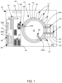
- a conventional liquid sampling probe 42 is located proximate to the second end of the input lane 35 and is operable to aspirate aliquot portions of sample fluid from sample fluid tubes 40 and to dispense an aliquot portion of the sample fluid into one or more of a plurality of vessels in aliquot vessel array 44. This provides a quantity of sample fluid to facilitate assays and to provide for a sample fluid aliquot to be retained by analyzer 10 within an environmental chamber 48.
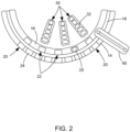
- Temperature-controlled storage areas or servers 26, 27, and 28 contain an inventory of multi-compartment elongated reagent cartridges 30 (shown in FIG. 2 ) loaded into the system via input tray 29, such as those described in U.S. Pat. No. 6,943,030 assigned to the assignee of the present invention.
- Cartridges 30 contain reagents in wells 32 to perform a number of different assays. Reagents may be moved and aligned within analyzer 10 by any conventional means, including those described in U.S. Patent Application Publication No. 2012/0127821 , also assigned to the assignee of the present invention.
- Computer 15 can control and track the motion and placement of the reagent cartridges 30. Reagents from server 26, 27, and 28 can be handled by one or more reagent probe arms 60, 61, and 62.
- FIG. 3 is a perspective view of an exemplary server ring 300 having a plurality of compartments 302 holding a multi-well fluid container 304.
- server ring 300 may hold any number of containers 304.
- container 304 may be used to hold reagent fluids.
- container 304 may be used to hold other fluids, such as patient samples.
- the compartments 302 of a server ring 300 may be wedge-shaped and the container 304 may be wedge-shaped to fit securely within a corresponding compartment 302.
- a compartment 302 may be configured to limit movement of containers 304 during operation.
- a compartment 302 may be shaped substantially the same as each container 304.
- multi-well wedge containers 304 may each have the same outer surface geometries and configured to be placed into wedge-shaped compartments 302 of the server ring 300.
- openable closures may be: (i) removable closures (e.g., threaded closures 408 removed by rotating and snap fit closures, magnetic closures and friction fit closures removed by pulling) that may be manually removed by an operator; and (ii) automatically openable closures (e.g., automatically openable closures in FIG. 5 that may include sealing portions 506 and 508 that may be opened by cannulas 510 and 512).
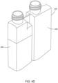
- container 304 may include a container body 402 that includes a first well 404 and a second well 406.
- First well 404 has a first well size configured to hold a first fluid (not shown).
- first well 404 has a removable first well closure 408 that covers a first well opening 410 when in a closed position.
- the first well opening 410 provides access to the first fluid in the first well when the removable first well closure 408 is removed from the closed position.
- first well 404 may also hold a first anti-evaporation tube 412.
- second well 406 is adjacent to first well 404 and has a second well size configured to hold a second fluid (not shown).
- the second fluid may be the same as the first fluid.
- the second fluid may be different from the first fluid.
- Second well 406 has a removable closure 416 that covers a second well opening 420 that is separate from the first well opening 410.
- the second well opening 420 is configured to provide access to the second fluid in the second well when the removable second well closure 416 is removed.
- Second well 404 may also be configured to hold a second anti-evaporation tube 418.
- the removable first well closure 408 and the removable second well closure 416 may include an induction seal film 414.
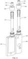
- embodiments may also include openable closures having openable sealing portions 504 and cannulas 502 configured to open the openable sealing portions.
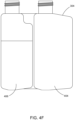
- the container 304 shown in the embodiment at FIG. 4A and FIG. 4B includes two wells.
- Embodiments may, however, include containers having any number of wells (e.g., three wells, four wells, etc.).
- each of the different sized wells 404 and 406 are configured to hold different volumes of reagents.
- the first well 404 may be configured (e.g., sized) to hold a low volume of the first fluid.
- the second well 406 is further configured (e.g., sized) to hold a high volume of the second fluid that is a larger volume than the low volume of the first fluid.
- a third sized well may be configured to hold a mid-volume of a third fluid that is larger than the low volume of the first fluid and smaller than the high volume of the second fluid.
- the size and shape of the wells of the multi-well container 304 shown in FIG. 4A and 4B is merely exemplary. Embodiments may include multi-well containers with wells of any size and shape. In some embodiments, different wells may be used to hold different fluids. In other embodiments, different wells may be used to hold the same fluids.
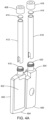
- FIG. 5 is an exploded view of an exemplary multi-well fluid container having cap closures 502 and 504 that include openable sealing portions 506 and 508 and cannulas 510 and 512 configured to open sealing portions 506 and 508 that can be used with embodiments disclosed herein.
- removable closures 502 and 504 include corresponding sealing portions 506 and 508.
- Removable closures 502 and 504 may also include corresponding cannulas 510 and 512 configured to open sealing portions 506 and 508.
- the removable first closure 408 and the removable second closure 416 are manually removed.
- some reagents may have different levels of open well stability.
- the less frequently used reagents having low-level open well stability may also be held within the smaller un-opened wells (e.g., well 406), of the container 304.
- these reagents are likely to be exposed for shorter amounts of time after the wells are opened. Accordingly, the likelihood of these reagents evaporating or becoming unstable due to exposure after the smaller wells (e.g., well 406) are opened decreases, and in turn, decreases the amount of unusable remaining reagents.
- a more efficient storage capacity may be obtained than with reagent bottles of different sizes (e.g., no wasted space).
- a probe (not shown) may move to the next opening to access another well (e.g., 406) of the multi-welled wedge container 304 rather than having to remove and replace the container 304 in the server ring 300, making scheduling easier and more efficient.
Landscapes
- Chemical & Material Sciences (AREA)
- Health & Medical Sciences (AREA)
- Chemical Kinetics & Catalysis (AREA)
- General Health & Medical Sciences (AREA)
- Analytical Chemistry (AREA)
- Life Sciences & Earth Sciences (AREA)
- Biochemistry (AREA)
- Physics & Mathematics (AREA)
- General Physics & Mathematics (AREA)
- Immunology (AREA)
- Pathology (AREA)
- Clinical Laboratory Science (AREA)
- Medicinal Chemistry (AREA)
- Engineering & Computer Science (AREA)
- Quality & Reliability (AREA)
- Hematology (AREA)
- Automatic Analysis And Handling Materials Therefor (AREA)
Claims (9)
- Récipient de fluide à multiples cavités (304) destiné à être utilisé dans un système d'automatisation de diagnostic in vitro comprenant :
un corps de récipient (402) comprenant :une première cavité (404) ayant une première taille de cavité configurée pour contenir un premier fluide et ayant un premier élément de fermeture de cavité pouvant être ouvert (502) qui recouvre une première ouverture de cavité (410), la première ouverture de cavité (410) est configurée pour permettre l'accès au premier fluide dans la première cavité (404) via la première ouverture de cavité (410) lorsque le premier élément de fermeture de cavité pouvant être ouvert (502) est ouvert ; etune deuxième cavité (406) adjacente à la première cavité (404), la deuxième cavité (406) ayant une deuxième taille de cavité configurée pour contenir un deuxième fluide et ayant un deuxième élément de fermeture de cavité pouvant être ouvert (504) qui recouvre une deuxième ouverture de cavité (420) qui est séparée de la première ouverture de cavité (410), la deuxième ouverture de cavité étant configurée pour permettre l'accès au deuxième fluide dans la deuxième cavité (406) via la deuxième ouverture de cavité (420) lorsque le deuxième élément de fermeture de cavité pouvant être ouvert (504) est ouvert,dans lequel le premier élément de fermeture de cavité pouvant être ouvert (502) comprend :une première partie d'étanchéité (506) configurée pour être ouverte par une première canule (510), etle deuxième élément de fermeture de cavité pouvant être ouvert (504) comprend :une deuxième partie d'étanchéité (508) configurée pour être ouverte par une deuxième canule (512),dans lequel la première cavité (404) et la deuxième cavité (406) comprennent chacun un tube anti-évaporation (412, 418),dans lequel la première taille de cavité de la première cavité (404) est différente de la deuxième taille de cavité de la deuxième cavité (406),dans lequel la première cavité est configurée pour contenir un faible volume du premier fluide et la deuxième cavité est configurée pour contenir un volume élevé du deuxième fluide qui est un volume plus important que le faible volume du premier fluide etdans lequel le premier élément de fermeture pouvant être ouvert (502) et le deuxième élément de fermeture pouvant être ouvert (504) sont configurés pour s'ouvrir automatiquement lorsqu'ils sont à bord d'un analyseur. - Récipient de fluide à multiples cavités (304) selon la revendication 1, dans lequel le corps de récipient (402) est en forme de coin et est en outre configuré pour être maintenu dans un compartiment d'une pluralité de compartiments en forme de coin (302) de taille sensiblement identique d'une zone de stockage circulaire (26, 27, 28).
- Récipient de fluide à multiples cavités (304) selon la revendication 1, comprenant en outre une troisième cavité configurée pour contenir un volume moyen d'un troisième fluide qui est d'un volume plus important que le faible volume du premier fluide et d'un volume plus petit que le volume élevé du deuxième fluide.
- Récipient de fluide à multiples cavités (304) selon la revendication 1, comprenant en outre une troisième cavité adjacente à au moins une cavité parmi la première cavité (404) et la deuxième cavité (406), la troisième cavité ayant une troisième taille de cavité configurée pour contenir un troisième fluide et ayant un troisième élément de fermeture de cavité pouvant être ouvert qui recouvre une troisième ouverture de cavité qui est séparée de la première ouverture de cavité (410) et de la deuxième ouverture de cavité (420), la troisième ouverture de cavité étant configurée pour permettre l'accès au troisième fluide dans la troisième cavité lorsque le troisième élément de fermeture de cavité pouvant être ouvert est ouvert.
- Système d'automatisation de diagnostic in vitro comprenant :
une pluralité de récipient de fluide à multiples cavités (304) de l'une des revendications 1 à 4. - Procédé d'exploitation d'un système d'automatisation de diagnostic in vitro, le procédé comprenant les étapes consistant à :maintenir un récipient de fluide à multiples cavités selon la revendication 1 dans un compartiment d'une pluralité de compartiments (302) d'une zone de stockageaccéder à un faible volume d'un premier fluide à partir de la première cavité (404) de la pluralité de cavités de différentes tailles via la première ouverture de cavité (410) lorsque le premier élément de fermeture de cavité pouvant être ouvert (502) est ouvert,accéder à un volume élevé d'un deuxième fluide à partir du deuxième cavité (406) de la pluralité de cavité de différentes tailles via la deuxième ouverture de cavité (420) lorsque le deuxième élément de fermeture pouvant être ouvert (504) est ouvert, le volume élevé du deuxième fluide étant un volume plus important que le faible volume du premier fluide,ouvrir automatiquement le premier élément de fermeture pouvant être ouvert (502) et le deuxième élément de fermeture pouvant être ouvert (504) à bord d'un analyseur (10),dans lequel le procédé comprend en outre les étapes consistant à :ouvrir la première partie d'étanchéité (506) du premier élément de fermeture pouvant être ouvert (502) à l'aide d'une première canule (510) pour permettre l'accès au faible volume du premier fluide de la première cavité (404),ouvrir la deuxième partie d'étanchéité (508) du deuxième élément de fermeture pouvant être ouvert (504) à l'aide d'une deuxième canule (512) pour permettre l'accès au volume élevé du deuxième fluide de la deuxième cavité (406), etretirer le récipient de fluide à multiples cavités (304) dudit compartiment de la pluralité de compartiments (302) de la zone de stockage (26, 27, 28).
- Procédé selon la revendication 6, dans lequel le retrait du récipient de fluide à multiples cavités (304) dudit compartiment de la pluralité de compartiments (302) de la zone de stockage (26, 27, 28) a lieu après qu'au moins une partie du faible volume du premier fluide est accessible de la première cavité (404) et qu'au moins une partie du volume élevé du deuxième fluide est accessible de la deuxième cavité (406).
- Procédé selon la revendication 6, comprenant en outre l'accès à un volume moyen d'un troisième fluide à partir d'une troisième cavité de la pluralité de cavité de tailles différentes, le volume moyen du troisième fluide étant plus grand que le faible volume du premier fluide et plus petit que le volume élevé du deuxième fluide.
- Procédé selon la revendication 8, dans lequel le retrait du récipient de fluide (304) dudit compartiment de la pluralité de compartiments (302) de la zone de stockage (27, 28) se produit après qu'au moins une partie du faible volume du premier fluide est accessible depuis la première cavité, qu'au moins une partie du volume élevé du deuxième fluide est accessible depuis la deuxième cavité (406) et qu'au moins une partie du volume moyen du troisième fluide est accessible depuis la troisième cavité.
Applications Claiming Priority (2)
| Application Number | Priority Date | Filing Date | Title |
|---|---|---|---|
| US201361900209P | 2013-11-05 | 2013-11-05 | |
| PCT/US2014/063232 WO2015069546A2 (fr) | 2013-11-05 | 2014-10-30 | Récipient à réactif cunéiforme à multiples cavités à capacité d'ouverture automatique |
Publications (4)
| Publication Number | Publication Date |
|---|---|
| EP3083059A2 EP3083059A2 (fr) | 2016-10-26 |
| EP3083059A4 EP3083059A4 (fr) | 2017-11-08 |
| EP3083059C0 EP3083059C0 (fr) | 2025-06-25 |
| EP3083059B1 true EP3083059B1 (fr) | 2025-06-25 |
Family
ID=53042301
Family Applications (1)
| Application Number | Title | Priority Date | Filing Date |
|---|---|---|---|
| EP14860937.3A Active EP3083059B1 (fr) | 2013-11-05 | 2014-10-30 | Récipient à réactif cunéiforme à multiples cavités à capacité d'ouverture automatique |
Country Status (3)
| Country | Link |
|---|---|
| US (1) | US9823261B2 (fr) |
| EP (1) | EP3083059B1 (fr) |
| WO (1) | WO2015069546A2 (fr) |
Families Citing this family (10)
| Publication number | Priority date | Publication date | Assignee | Title |
|---|---|---|---|---|
| IES86617B2 (en) * | 2014-05-27 | 2016-01-27 | Beckman Coulter Inc | Reagent bottle with aspiration pipe |
| EP3478414A4 (fr) * | 2016-07-01 | 2019-05-08 | Siemens Healthcare Diagnostics Inc. | Capuchon amovible à joint conçu pour être ouvert par perçage dans un analyseur de diagnostic |
| WO2018005240A1 (fr) * | 2016-07-01 | 2018-01-04 | Siemens Healthcare Diagnostics Inc. | Capuchon et opercule soudé par induction destinés à être ouverts par perçage dans un analyseur de diagnostic |
| EP3589408A1 (fr) * | 2017-03-03 | 2020-01-08 | Gen-Probe Incorporated | Inserts limitant l'évaporation pour récipients de réactifs et procédés d'utilisation associés |
| US11541396B2 (en) * | 2018-03-30 | 2023-01-03 | Idexx Laboratories, Inc. | Point-of-care diagnostic systems and containers for same |
| JP7305846B2 (ja) | 2018-03-30 | 2023-07-10 | アイデックス ラボラトリーズ インコーポレイテッド | ポイント・オブ・ケア診断システム及びその容器 |
| US11358148B2 (en) | 2018-03-30 | 2022-06-14 | Idexx Laboratories, Inc. | Point-of-care diagnostic systems and containers for same |
| US11992844B2 (en) | 2018-11-13 | 2024-05-28 | Becton, Dickinson And Company | Dried reagent strainers and methods for making and using the same |
| US20230398546A1 (en) * | 2022-06-09 | 2023-12-14 | Becton, Dickinson And Company | Systems for reconstituting dried reagent compositions and methods for using the same |
| LU103025B1 (en) * | 2022-09-27 | 2024-03-28 | Stratec Se | Drawer for bulk liquid supply |
Family Cites Families (33)
| Publication number | Priority date | Publication date | Assignee | Title |
|---|---|---|---|---|
| US3361387A (en) | 1965-03-04 | 1968-01-02 | Arthur D. Struble Jr. | Balloon systems |
| US4713064A (en) | 1985-04-30 | 1987-12-15 | Sherwood Medical Company | Enteral feeding devices |
| DE3750446T2 (de) * | 1986-07-11 | 1994-12-22 | Beckman Instruments Inc | Reagenzkassette. |
| US4970053A (en) * | 1986-07-11 | 1990-11-13 | Beckman Instruments, Inc. | Reagent cartridge |
| US4935274A (en) * | 1988-08-26 | 1990-06-19 | E. I. Du Pont De Nemours And Company | Lid structure |
| US4925066A (en) | 1988-10-26 | 1990-05-15 | Mission Kleensweep Products, Inc. | Combined sprayer and refill container |
| US5102631A (en) * | 1989-12-18 | 1992-04-07 | Abbott Laboratories | Evaporation chimney |
| US5578494A (en) * | 1992-03-27 | 1996-11-26 | Abbott Laboratories | Cap actuator for opening and closing a container |
| US5542575A (en) * | 1993-07-09 | 1996-08-06 | Dade Interantional Inc. | Liquid reagent container having a primary and secondary closure mechanism |
| DE19536789A1 (de) | 1995-10-02 | 1997-04-03 | Boehringer Mannheim Gmbh | Gefäß für Flüssigkeiten |
| DE19540877C2 (de) | 1995-11-02 | 1998-02-26 | Byk Sangtec Diagnostica | Modulare Reagenzienkartusche |
| US5885529A (en) * | 1996-06-28 | 1999-03-23 | Dpc Cirrus, Inc. | Automated immunoassay analyzer |
| US5632399A (en) * | 1996-06-28 | 1997-05-27 | Dpc Cirrus Inc. | Self-sealing reagent container and reagent container system |
| AU3651497A (en) | 1996-07-05 | 1998-02-02 | Beckman Coulter, Inc. | Automated sample processing system |
| US5928681A (en) | 1997-04-08 | 1999-07-27 | Crown Cork & Seal Technologies Corporation | Multi-chambered container production mold |
| US6824738B1 (en) | 2000-04-14 | 2004-11-30 | Discovery Partners International, Inc. | System and method for treatment of samples on solid supports |
| US7666363B2 (en) * | 2001-09-05 | 2010-02-23 | Quest Diagnostics Investments Incorporated | Reagent cartridge |
| US6857530B2 (en) | 2002-02-26 | 2005-02-22 | Graham Packaging Company, L.P. | Package of interengaging containers for companion products |
| US7381370B2 (en) * | 2003-07-18 | 2008-06-03 | Dade Behring Inc. | Automated multi-detector analyzer |
| US7235163B2 (en) | 2003-09-12 | 2007-06-26 | Applera Corporation | Loading features for channel array |
| US20060172433A1 (en) * | 2005-01-28 | 2006-08-03 | Arta Motadel | Liquid sampling utilizing ribbed pipette tip for barrier penetration |
| EP1707267A1 (fr) * | 2005-03-30 | 2006-10-04 | F. Hoffman-la Roche AG | dispositif avec port refermable |
| US20090129987A1 (en) * | 2005-05-17 | 2009-05-21 | Wako Pure Chemical Industries, Ltd. | Connected Reagent Container |
| US8728413B2 (en) * | 2007-02-08 | 2014-05-20 | Biokit, S.A. | Reagent container pack |
| US8387810B2 (en) | 2007-04-16 | 2013-03-05 | Becton, Dickinson And Company | Pierceable cap having piercing extensions for a sample container |
| US8556564B2 (en) | 2007-06-26 | 2013-10-15 | Siemens Healthcare Diagnostics Inc. | Mobile sample storage and retrieval unit for a laboratory automated sample handling worksystem |
| JP5272205B2 (ja) * | 2007-09-25 | 2013-08-28 | 和光純薬工業株式会社 | 試薬容器 |
| US8691149B2 (en) | 2007-11-06 | 2014-04-08 | Abbott Laboratories | System for automatically loading immunoassay analyzer |
| JP2011516075A (ja) | 2008-04-09 | 2011-05-26 | バイオニア コーポレーション | 自動精製装置、マルチウェルプレートキット及び生物学的試料からヘキサンを抽出する方法 |
| FI120818B (fi) | 2008-05-28 | 2010-03-31 | Thermo Fisher Scientific Oy | Reaktioastia ja menetelmä sen käsittelemiseksi |
| JP5250050B2 (ja) | 2009-01-27 | 2013-07-31 | 株式会社日立ハイテクノロジーズ | 自動分析装置および自動分析方法 |
| CN102917795B (zh) | 2010-05-03 | 2014-11-12 | 因特格拉生物科学股份公司 | 手动导向式多道电子移液系统 |
| FR2960454B1 (fr) | 2010-06-01 | 2012-11-30 | Stago Diagnostica | Dispositif pour reduire l'evaporation dans un flacon de reactif |
-
2014
- 2014-10-30 WO PCT/US2014/063232 patent/WO2015069546A2/fr not_active Ceased
- 2014-10-30 EP EP14860937.3A patent/EP3083059B1/fr active Active
- 2014-10-30 US US15/034,608 patent/US9823261B2/en active Active
Also Published As
| Publication number | Publication date |
|---|---|
| WO2015069546A2 (fr) | 2015-05-14 |
| US9823261B2 (en) | 2017-11-21 |
| EP3083059A2 (fr) | 2016-10-26 |
| WO2015069546A3 (fr) | 2015-11-12 |
| US20160266155A1 (en) | 2016-09-15 |
| EP3083059A4 (fr) | 2017-11-08 |
| EP3083059C0 (fr) | 2025-06-25 |
Similar Documents
| Publication | Publication Date | Title |
|---|---|---|
| EP3083059B1 (fr) | Récipient à réactif cunéiforme à multiples cavités à capacité d'ouverture automatique | |
| CN102818907B (zh) | 自动分析仪 | |
| US7670553B2 (en) | Carousel system for automated chemical or biological analyzers employing linear racks | |
| EP2546655B1 (fr) | Instrument et procédé de traitement automatique d'échantillons liquides | |
| US6752967B2 (en) | Stackable aliquot vessel array | |
| US20100322822A1 (en) | System for managing inventory of bulk liquids | |
| US8728413B2 (en) | Reagent container pack | |
| JPH09225U (ja) | 試薬キットと自動分析装置 | |
| EP2743703B1 (fr) | Procédé pour supporter de multiples types de produits consommables de test diagnostique dans un récipient unique à accès aléatoire | |
| CN106053864A (zh) | 试剂管理系统 | |
| US9731847B2 (en) | Method for holding multiple types of diagnostic test consumables in a random access single container | |
| CN102292645A (zh) | 自动分析装置及自动分析方法 | |
| EP2804002A1 (fr) | Système automatisé de laboratoire ayant un module de routage d'échantillones commun | |
| US4960219A (en) | Snap cap | |
| EP1648612B1 (fr) | Magasin pour inventorier les cuvettes de reaction dans un analyseur automatique | |
| EP2962118B1 (fr) | Récipient à cale d'auto-alignement pourvu d'un tube anti-évaporation | |
| EP3032265B1 (fr) | Dispositif de stockage de récipients de fluide | |
| JPH06509175A (ja) | 医療用自動分析装置用試薬処理システム | |
| HK1227095A1 (en) | Reagent management system |
Legal Events
| Date | Code | Title | Description |
|---|---|---|---|
| PUAI | Public reference made under article 153(3) epc to a published international application that has entered the european phase |
Free format text: ORIGINAL CODE: 0009012 |
|
| 17P | Request for examination filed |
Effective date: 20160607 |
|
| AK | Designated contracting states |
Kind code of ref document: A2 Designated state(s): AL AT BE BG CH CY CZ DE DK EE ES FI FR GB GR HR HU IE IS IT LI LT LU LV MC MK MT NL NO PL PT RO RS SE SI SK SM TR |
|
| AX | Request for extension of the european patent |
Extension state: BA ME |
|
| DAX | Request for extension of the european patent (deleted) | ||
| A4 | Supplementary search report drawn up and despatched |
Effective date: 20171009 |
|
| RIC1 | Information provided on ipc code assigned before grant |
Ipc: B01L 3/00 20060101AFI20171002BHEP Ipc: G01N 35/00 20060101ALI20171002BHEP |
|
| STAA | Information on the status of an ep patent application or granted ep patent |
Free format text: STATUS: EXAMINATION IS IN PROGRESS |
|
| 17Q | First examination report despatched |
Effective date: 20210412 |
|
| GRAP | Despatch of communication of intention to grant a patent |
Free format text: ORIGINAL CODE: EPIDOSNIGR1 |
|
| STAA | Information on the status of an ep patent application or granted ep patent |
Free format text: STATUS: GRANT OF PATENT IS INTENDED |
|
| INTG | Intention to grant announced |
Effective date: 20250129 |
|
| GRAS | Grant fee paid |
Free format text: ORIGINAL CODE: EPIDOSNIGR3 |
|
| GRAA | (expected) grant |
Free format text: ORIGINAL CODE: 0009210 |
|
| STAA | Information on the status of an ep patent application or granted ep patent |
Free format text: STATUS: THE PATENT HAS BEEN GRANTED |
|
| AK | Designated contracting states |
Kind code of ref document: B1 Designated state(s): AL AT BE BG CH CY CZ DE DK EE ES FI FR GB GR HR HU IE IS IT LI LT LU LV MC MK MT NL NO PL PT RO RS SE SI SK SM TR |
|
| REG | Reference to a national code |
Ref country code: GB Ref legal event code: FG4D |
|
| REG | Reference to a national code |
Ref country code: CH Ref legal event code: EP |
|
| REG | Reference to a national code |
Ref country code: DE Ref legal event code: R096 Ref document number: 602014092072 Country of ref document: DE |
|
| REG | Reference to a national code |
Ref country code: CH Ref legal event code: EP |
|
| REG | Reference to a national code |
Ref country code: IE Ref legal event code: FG4D |
|
| U01 | Request for unitary effect filed |
Effective date: 20250703 |
|
| U07 | Unitary effect registered |
Designated state(s): AT BE BG DE DK EE FI FR IT LT LU LV MT NL PT RO SE SI Effective date: 20250710 |
|
| PG25 | Lapsed in a contracting state [announced via postgrant information from national office to epo] |
Ref country code: NO Free format text: LAPSE BECAUSE OF FAILURE TO SUBMIT A TRANSLATION OF THE DESCRIPTION OR TO PAY THE FEE WITHIN THE PRESCRIBED TIME-LIMIT Effective date: 20250925 Ref country code: GR Free format text: LAPSE BECAUSE OF FAILURE TO SUBMIT A TRANSLATION OF THE DESCRIPTION OR TO PAY THE FEE WITHIN THE PRESCRIBED TIME-LIMIT Effective date: 20250926 |
|
| PG25 | Lapsed in a contracting state [announced via postgrant information from national office to epo] |
Ref country code: HR Free format text: LAPSE BECAUSE OF FAILURE TO SUBMIT A TRANSLATION OF THE DESCRIPTION OR TO PAY THE FEE WITHIN THE PRESCRIBED TIME-LIMIT Effective date: 20250625 |
|
| PG25 | Lapsed in a contracting state [announced via postgrant information from national office to epo] |
Ref country code: RS Free format text: LAPSE BECAUSE OF FAILURE TO SUBMIT A TRANSLATION OF THE DESCRIPTION OR TO PAY THE FEE WITHIN THE PRESCRIBED TIME-LIMIT Effective date: 20250925 |
|
| U20 | Renewal fee for the european patent with unitary effect paid |
Year of fee payment: 12 Effective date: 20251020 |
|
| PG25 | Lapsed in a contracting state [announced via postgrant information from national office to epo] |
Ref country code: IS Free format text: LAPSE BECAUSE OF FAILURE TO SUBMIT A TRANSLATION OF THE DESCRIPTION OR TO PAY THE FEE WITHIN THE PRESCRIBED TIME-LIMIT Effective date: 20251025 |
|
| PGFP | Annual fee paid to national office [announced via postgrant information from national office to epo] |
Ref country code: GB Payment date: 20251111 Year of fee payment: 12 |
|
| PG25 | Lapsed in a contracting state [announced via postgrant information from national office to epo] |
Ref country code: SM Free format text: LAPSE BECAUSE OF FAILURE TO SUBMIT A TRANSLATION OF THE DESCRIPTION OR TO PAY THE FEE WITHIN THE PRESCRIBED TIME-LIMIT Effective date: 20250625 |
|
| PG25 | Lapsed in a contracting state [announced via postgrant information from national office to epo] |
Ref country code: CZ Free format text: LAPSE BECAUSE OF FAILURE TO SUBMIT A TRANSLATION OF THE DESCRIPTION OR TO PAY THE FEE WITHIN THE PRESCRIBED TIME-LIMIT Effective date: 20250625 |
|
| PG25 | Lapsed in a contracting state [announced via postgrant information from national office to epo] |
Ref country code: PL Free format text: LAPSE BECAUSE OF FAILURE TO SUBMIT A TRANSLATION OF THE DESCRIPTION OR TO PAY THE FEE WITHIN THE PRESCRIBED TIME-LIMIT Effective date: 20250625 |
|
| PG25 | Lapsed in a contracting state [announced via postgrant information from national office to epo] |
Ref country code: SK Free format text: LAPSE BECAUSE OF FAILURE TO SUBMIT A TRANSLATION OF THE DESCRIPTION OR TO PAY THE FEE WITHIN THE PRESCRIBED TIME-LIMIT Effective date: 20250625 |
|
| PG25 | Lapsed in a contracting state [announced via postgrant information from national office to epo] |
Ref country code: ES Free format text: LAPSE BECAUSE OF FAILURE TO SUBMIT A TRANSLATION OF THE DESCRIPTION OR TO PAY THE FEE WITHIN THE PRESCRIBED TIME-LIMIT Effective date: 20250625 |