EP3083401B1 - Flugzeugsitzaufständervorrichtung - Google Patents
Flugzeugsitzaufständervorrichtung Download PDFInfo
- Publication number
- EP3083401B1 EP3083401B1 EP14814838.0A EP14814838A EP3083401B1 EP 3083401 B1 EP3083401 B1 EP 3083401B1 EP 14814838 A EP14814838 A EP 14814838A EP 3083401 B1 EP3083401 B1 EP 3083401B1
- Authority
- EP
- European Patent Office
- Prior art keywords
- aircraft seat
- carrier profile
- seat
- aircraft
- elements
- Prior art date
- Legal status (The legal status is an assumption and is not a legal conclusion. Google has not performed a legal analysis and makes no representation as to the accuracy of the status listed.)
- Active
Links
Images

Classifications
-
- B—PERFORMING OPERATIONS; TRANSPORTING
- B64—AIRCRAFT; AVIATION; COSMONAUTICS
- B64D—EQUIPMENT FOR FITTING IN OR TO AIRCRAFT; FLIGHT SUITS; PARACHUTES; ARRANGEMENT OR MOUNTING OF POWER PLANTS OR PROPULSION TRANSMISSIONS IN AIRCRAFT
- B64D11/00—Passenger or crew accommodation; Flight-deck installations not otherwise provided for
- B64D11/06—Arrangements of seats, or adaptations or details specially adapted for aircraft seats
- B64D11/0696—Means for fastening seats to floors, e.g. to floor rails
-
- B—PERFORMING OPERATIONS; TRANSPORTING
- B64—AIRCRAFT; AVIATION; COSMONAUTICS
- B64D—EQUIPMENT FOR FITTING IN OR TO AIRCRAFT; FLIGHT SUITS; PARACHUTES; ARRANGEMENT OR MOUNTING OF POWER PLANTS OR PROPULSION TRANSMISSIONS IN AIRCRAFT
- B64D11/00—Passenger or crew accommodation; Flight-deck installations not otherwise provided for
- B64D11/06—Arrangements of seats, or adaptations or details specially adapted for aircraft seats
-
- B—PERFORMING OPERATIONS; TRANSPORTING
- B64—AIRCRAFT; AVIATION; COSMONAUTICS
- B64D—EQUIPMENT FOR FITTING IN OR TO AIRCRAFT; FLIGHT SUITS; PARACHUTES; ARRANGEMENT OR MOUNTING OF POWER PLANTS OR PROPULSION TRANSMISSIONS IN AIRCRAFT
- B64D11/00—Passenger or crew accommodation; Flight-deck installations not otherwise provided for
- B64D11/06—Arrangements of seats, or adaptations or details specially adapted for aircraft seats
- B64D11/0606—Arrangements of seats, or adaptations or details specially adapted for aircraft seats with privacy shells, screens, separators or the like
-
- B—PERFORMING OPERATIONS; TRANSPORTING
- B64—AIRCRAFT; AVIATION; COSMONAUTICS
- B64D—EQUIPMENT FOR FITTING IN OR TO AIRCRAFT; FLIGHT SUITS; PARACHUTES; ARRANGEMENT OR MOUNTING OF POWER PLANTS OR PROPULSION TRANSMISSIONS IN AIRCRAFT
- B64D11/00—Passenger or crew accommodation; Flight-deck installations not otherwise provided for
- B64D11/06—Arrangements of seats, or adaptations or details specially adapted for aircraft seats
- B64D11/0649—Seats characterised by special features for reducing weight
-
- Y—GENERAL TAGGING OF NEW TECHNOLOGICAL DEVELOPMENTS; GENERAL TAGGING OF CROSS-SECTIONAL TECHNOLOGIES SPANNING OVER SEVERAL SECTIONS OF THE IPC; TECHNICAL SUBJECTS COVERED BY FORMER USPC CROSS-REFERENCE ART COLLECTIONS [XRACs] AND DIGESTS
- Y02—TECHNOLOGIES OR APPLICATIONS FOR MITIGATION OR ADAPTATION AGAINST CLIMATE CHANGE
- Y02T—CLIMATE CHANGE MITIGATION TECHNOLOGIES RELATED TO TRANSPORTATION
- Y02T50/00—Aeronautics or air transport
- Y02T50/40—Weight reduction
Definitions
- the invention relates to an aircraft seat stand device according to the preamble of patent claim 1.
- An aircraft seat stand device with at least one carrier profile, with at least one aircraft seat element and with at least one intermediate element, which at least substantially surrounds the at least one carrier profile and is coupled to the at least one aircraft seat element has already been proposed.
- document EP0423348 discloses an aircraft seat stand device with at least one carrier profile, with at least one aircraft seat element designed as a seat divider or as a seat foot and with at least one intermediate element which at least substantially encloses the at least one carrier profile and is coupled to the at least one aircraft seat element, the intermediate element being in an axial direction to the carrier profile , on which it is arranged, fixed, the intermediate element being arranged rotatably to the carrier profile at least in the event of a crash / deformation, as a result of which torsional loads on the carrier profile are prevented or minimized.
- the object of the invention is in particular to provide a generic device with improved properties with regard to weight and resilience.
- the object is achieved by the features of patent claim 1, while advantageous refinements and developments of the invention can be found in the subclaims.
- the invention is based on an aircraft seat stand device with at least one carrier profile, with at least one aircraft seat element and with at least one intermediate element, which at least substantially encloses the at least one carrier profile and is coupled to the at least one aircraft seat element.
- an “aircraft seat stand device” is to be understood in particular to mean a device which forms part of an aircraft seat, in particular a part by means of which the aircraft seat is erected on a cabin floor.
- the aircraft seat stand device is provided for this purpose during operation in the Forces introduced into the cabin floor, such as a weight force of a person sitting on the airplane seat, into the cabin floor.
- a “support profile” is to be understood to mean in particular an element of an aircraft seat, in particular part of a frame of the aircraft seat, the support profile preferably being designed as a cross tube which runs parallel to a transverse direction of the seat.
- the carrier profile is preferably part of a plurality of aircraft seats arranged side by side in an aircraft seat row.
- An “aircraft seat element” is to be understood in particular to mean a part of the aircraft seat which forms a load-bearing part of the aircraft seat.
- a seat element transmits forces that occur during operation and forwards them.
- the aircraft seat element is preferably designed as a seat divider or a seat foot.
- An “intermediate element” is to be understood in particular to mean an element which is arranged between two elements, in particular between at least one aircraft seat element and the carrier profile, these two elements being coupled to one another via the intermediate element.
- At least essentially enclose is to be understood here in particular to mean that the intermediate element completely encloses the carrier profile at least to more than 180 degrees, preferably to more than 270 degrees and in a particularly advantageous embodiment.
- the phrase that two elements are “coupled” to one another is to be understood in particular to mean that the two elements, such as in particular the intermediate element and the aircraft seat element, are firmly connected to one another, that is to say are firmly positioned relative to one another, the two elements being rigid or but can also be articulated together.
- one of the elements preferably has a connecting block, via which the other element is connected to the one element.
- a “crash case” is to be understood to mean in particular an overload case, that is to say an operating state in which forces act on the aircraft seat support device and / or the aircraft seat, the part of which is the aircraft seat support device, which are greater than forces which are caused by a normal load on one normal flight operations arise.
- the aircraft seat element can be connected particularly advantageously and simply via the intermediate element, and forces can be dissipated particularly easily via the intermediate element in the event of a crash without additionally stressing the carrier profile on torsion, as a result of which in particular, the carrier profile can be formed with a particularly advantageous low weight.
- the aircraft seat stand device has at least one further aircraft seat element which is coupled to the intermediate element.
- the two aircraft seat elements can be coupled to one another in a particularly advantageous manner and forces can be transmitted between the two aircraft seat elements.
- the aircraft seat element be designed as a seat divider.
- a “seat divider” is to be understood in particular to mean a component of an aircraft seat row with at least two aircraft seats arranged laterally next to one another, with respect to a vertical direction oriented vertically to a support plane of the aircraft seat row at least essentially above at least one support profile, in particular a single beam and / or a cross tube, is arranged.
- the seat divider is a rigid component of the aircraft seat row.
- the seat divider is preferably arranged at least essentially with respect to the vertical direction above a seat bottom of a respective aircraft seat of the at least two aircraft seats of the aircraft seat row arranged laterally next to one another.
- the seat divider is particularly intended to support an armrest unit.
- the seat divider is preferably provided to enable a belt connection.
- the seat divider preferably forms a lateral boundary of at least one of the at least two aircraft seats arranged laterally next to one another, the seat divider being able to be arranged on the aisle side and / or on the board side and / or forming a boundary between two aircraft seats of the at least two aircraft seats arranged laterally next to one another.
- the aircraft seat element can be embodied particularly advantageously.
- the aircraft seat element is designed as a seat foot.
- a “seat foot” is to be understood in particular to mean an element which connects the aircraft seat to a cabin floor on which the aircraft seat, the part of which is the aircraft seat stand device, is mounted, the seat foot at a lower end preferably being connected to the cabin floor by means of a connecting element connected and coupled to the support profile at an upper end.
- the seat foot of the aircraft seat can be connected to the carrier profile in a particularly advantageous manner.
- connection bracket is to be understood in particular to mean an element which has at least one receptacle for fastening a further element, such as in particular the aircraft seat element.
- connection bracket is integrally coupled to the intermediate element.
- “Materially coupled” is to be understood in particular to mean that parts of the mass of the elements to be coupled are held together by atomic or molecular forces, such as, for example, by soldering, welding, gluing and / or vulcanizing.
- the connection bracket can be coupled to the intermediate element in a particularly simple, cost-effective and secure manner.
- connection block has an extension in the connection area with the intermediate element in the circumferential direction that is less than 180 degrees.
- a “connection area” is to be understood in particular to mean an area in which the connection block is connected to the intermediate element.
- connection bracket can be designed to be particularly advantageous and space-saving, it being particularly advantageous for at least two connection brackets to be arranged in the same circumferential area.
- elements connected to the connecting brackets such as, in particular, aircraft seat elements, can be connected to the intermediate element particularly advantageously in one plane.
- the at least one intermediate element is fixed to the carrier profile at least in an axial direction.
- An “axial direction” is to be understood in particular to mean a direction which corresponds to the main direction of extent of the carrier profile.
- the axial direction is preferably oriented transversely to a seat direction. In this way, the intermediate element and thereby the aircraft seat elements connected to the intermediate element can be advantageously positioned for operation.
- the intermediate element is arranged in a rotationally fixed manner relative to the carrier profile, at least in one operating state.
- rotationally fixed is to be understood in particular to mean that the intermediate element cannot be rotated relative to the carrier profile.
- the intermediate element can be particularly advantageously coupled to the carrier profile for a normal operating state.
- the intermediate element is fixedly connected to the carrier profile at least in an operating state by means of an adhesive connection.
- the intermediate element can advantageously be connected to the carrier profile in a particularly simple and cost-effective manner.
- the carrier profile be formed at least essentially from a light metal and / or a fiber composite material.
- “At least essentially formed from a light metal” is to be understood here in particular to mean that the carrier profile is formed at least 60%, preferably more than 80% and, in a particularly advantageous embodiment, completely from a light metal.
- a light metal is to be understood in particular to mean a metal with a density of less than 5 g / cm 3 , such as in particular an aluminum, titanium or magnesium.
- other aircraft seat elements such as a seat divider or a seat foot, can also consist of these materials.
- the carrier profile can be made particularly light.
- the aircraft seat stand device has at least one second intermediate element, an aircraft seat element being coupled to one of the two intermediate elements.
- a further “intermediate element” is to be understood in particular to mean an additional intermediate element which is different from the one intermediate element and is formed separately.
- the two aircraft seat elements can be particularly advantageously coupled to the carrier profile via a separate intermediate element.
- the aircraft seat stand device has at least one further aircraft seat element that is directly coupled to the carrier profile.
- Coupled is to be understood in particular to be firmly connected to one another, the aircraft seat element preferably being rigidly connected to the carrier profile. As a result, the one aircraft seat element can be particularly advantageously coupled to the carrier profile.
- the aircraft seat stand device according to the invention is not intended to be limited to the application and embodiment described above.
- the aircraft seat stand device according to the invention can have a number that differs from a number of individual elements, components and units specified here in order to fulfill a function described here.
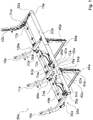
- the Figures 1 to 3 show a first embodiment of an aircraft seat stand device according to the invention.
- the aircraft seat stand device is part of an aircraft seat row 56a which is only partially shown.
- the aircraft seat row 56a comprises three aircraft seats 58a.
- the row of aircraft seats 56a comprises a different number, for example only one, two or four aircraft seats 58a.
- the aircraft seats 58a are provided so that passengers can sit on them during a flight.
- the aircraft seats 58a each have a seat bottom (not shown) and a backrest (not shown).
- each aircraft seat 58a is laterally delimited by an armrest (not shown in more detail).
- Two directly adjacent aircraft seats 58a each have a common armrest.
- the aircraft seats 58a are intended to be erected on a stand level.
- the stand level is formed by a cabin floor of an aircraft.
- the aircraft seats 58a are mounted on the cabin floor in an assembled state by means of the aircraft seat stand device.
- the aircraft seat stand device comprises a first carrier profile 10a.
- the first carrier profile 10a is designed as a front cross tube.
- the aircraft seat stand device further comprises a second carrier profile 12a.
- the second support profile 12a is designed as a rear cross tube.
- the two carrier profiles 10a, 12a are arranged at a distance from one another and run parallel to one another.
- the carrier profile 10a designed as a front cross tube is arranged in a front region of the aircraft seats 58a.
- the second carrier profile 12a which is designed as a rear cross tube, is arranged in a rear region of the aircraft seats 58a.
- the carrier profiles 10a, 12a extend in a transverse direction to the aircraft seats 58a.
- the transverse direction of the aircraft seats 58a is oriented at right angles to a seat direction.
- the two support profiles 10a, 12a designed as cross tubes are essentially identical, which is why only the first support profile 10a, which is designed as a front cross tube, is described in more detail below.
- a description of the first support profile 10a can be used to explain the second support profile 12a, which is designed as a rear cross tube.
- the carrier profile 10a designed as a cross tube is tubular.
- the carrier profile 10a has a cross section, that forms a ring.
- the carrier profile 10a is thin-walled.
- the carrier profile 10a is formed from a fiber composite material. In principle, it is also conceivable that the carrier profile 10a is formed from a light metal, such as an aluminum or magnesium.
- the aircraft seat stand device comprises four first aircraft seat elements 14a, 16a, 18a, 42a.
- the first aircraft seat elements 14a, 16a, 18a, 42a are each designed as a seat divider.
- the first aircraft seat elements 14a, 16a, 18a, 42a designed as seat dividers each delimit a seating area of an aircraft seat 58a.
- two adjacent aircraft seat elements 14a, 16a, 18a, 42a designed as seat dividers delimit an aircraft seat 58a of the aircraft seat row 56a.
- the aircraft seat elements 14a, 16a, 18a, 42a are L-shaped and, in an assembled state, extend from the first support profile 10a designed as a front cross tube to the second support profile 12a designed as a rear cross tube. In the assembled state, the aircraft seat elements 14a, 16a, 18a, 42a designed as seat dividers extend from the first support profile 10a designed as a front cross tube to behind the second support profile 12a designed as a rear cross tube.
- the first aircraft seat elements 14a, 16a, 18a, 42a which are designed as seat dividers, have a kink, from which the aircraft seat elements 14a, 16a, 18a, 42a move upward from the support profiles 10a, 12a , extend away from the insurgent level.
- the first aircraft seat elements 14a, 16a, 18a, 42a which are designed as seat dividers, are each coupled to the carrier profile 12a, which is designed as a rear cross tube.
- the first aircraft seat elements 14a, 16a, 18a, 42a designed as a seat divider, they are each coupled to the support profile 10a designed as a front cross tube.
- the first aircraft seat elements 14a, 16a, 18a, 42a designed as seat dividers each have a receptacle 60a at the front end.
- the receptacle 60a is formed by a through hole.
- the aircraft seat elements 14a, 16a, 18a, 42a, which are designed as seat dividers, are provided so that further components of the aircraft seats 58a or the aircraft seat row 56a, such as in particular armrests and / or backrests, are attached.
- the first aircraft seat elements 14a, 16a, 18a, 42a, which are designed as seat dividers are formed from a light metal, such as in particular an aluminum.
- the outer two first aircraft seat elements designed as seat dividers 18a, 42a configured differently than the inner two first aircraft seat elements 14a, 16a, which are designed as seat dividers.
- the aircraft seat elements 14a, 16a, 18a, 42a are all the same and / or are made of another material, such as a fiber composite material.
- the aircraft seat stand device has a different number of aircraft seat elements 14a, 16a, 18a, 42a designed as seat dividers.
- the aircraft seat stand device comprises four second aircraft seat elements 44a, 46a, 48a, 50a.
- the second aircraft seat elements 44a, 46a, 48a, 50a are each designed as a seat base.
- the second aircraft seat elements 44a, 46a, 48a, 50a, which are designed as seat feet, are intended to stand the aircraft seat stand device and thus the aircraft seat row 56a on the stand level.
- the two second aircraft seat elements 44a, 46a are designed as front seat feet and the other two second aircraft seat elements 48a, 50a as rear seat feet.
- the second aircraft seat elements 44a, 46a, which are designed as front seat feet are coupled in an assembled state to the first carrier profile 10a, which is designed as a front cross tube.
- the second aircraft seat elements 48a, 50a which are designed as rear seat feet, are coupled in an assembled state to the second carrier profile 12a, which is designed as a rear cross tube.
- the second aircraft seat elements 44a, 46a, 48a, 50a are each coupled with an upper end to the respective carrier profile 10a, 12a.
- the second aircraft seat elements 44a, 46a, 48a, 50a each have a receptacle 62a at an upper end.
- the receptacles 62a are each formed by two through holes.
- the second aircraft seat elements 44a, 46a, 48a, 50a which are designed as seat feet, each have connecting elements, which are not shown or described in any more detail, via which the second aircraft seat elements 44a, 46a, 48a, 50a, which are designed as seat feet, are connected to connecting elements introduced into the cabin floor can be.
- the connecting elements of the cabin floor are preferably designed as connecting rails.
- the connecting elements of the second aircraft seat elements 44a, 46a, 48a, 50a, which are designed as seat feet, are designed as fittings which engage positively in the connecting elements, which are designed as connecting rails, for elevating the aircraft seat row 56a.
- the second aircraft seat elements 44a, 46a, 48a, 50a designed as seat feet are different have trained connecting elements that fix the second aircraft seat elements 44a, 46a, 48a, 50a in another way firmly on a stand level.
- the two second aircraft seat elements 44a, 46a, which are designed as front seat feet are designed as essentially straight profiles which, in an assembled state, extend essentially vertically downward from the first carrier profile 10a.
- the two second aircraft seat elements 48a, 50a, which are designed as rear seat feet, are designed as curved profiles which extend both downwards and backwards from the second carrier profile 12a, that is to say away from the first carrier profile 10a.
- one of the second aircraft seat elements 44a, 46a designed as a front seat base is aligned parallel to one of the second aircraft seat elements 48a, 50a designed as a rear seat base.
- the second aircraft seat element 44a, 46a, which is designed as a front seat base, and the second aircraft seat element 48a, 50a, which is designed as a rear seat base, and which are aligned parallel to one another, are each connected to one another at a lower end by means of a connecting rod 64a, 66a.
- the aircraft seat stand device comprises a first intermediate element 20a and a second intermediate element 22a.
- the intermediate elements 20a, 22a completely surround the first carrier profile 10a, which is designed as a front cross tube. In principle, it would also be conceivable that the intermediate elements 20a, 22a only partially surround the first carrier profile 10a in the circumferential direction.
- the intermediate elements 20a, 22a are designed as tubular elements.
- the intermediate elements 20a, 22a, which are designed as tubular elements, are formed from a fiber composite material. In principle, it is also conceivable for the intermediate elements 20a, 22a to be formed from a different material, such as preferably a light metal, such as an aluminum.
- the first intermediate element 20a is coupled to the first aircraft seat element 14a designed as a seat divider.
- first intermediate element 20a is connected to the one second aircraft seat element 44a designed as a front seat foot.
- the first intermediate element 20a is provided for connecting the first aircraft seat element 14a, which is designed as a seat divider, and the second aircraft seat element 44a, which is designed as a front seat base, to the first carrier profile 10a, which is designed as a front cross tube.
- the second intermediate element 22a is provided for connecting the other first aircraft seat element 16a, which is designed as a seat divider, and the other second aircraft seat element 46a, which is designed as a front seat base, to the first carrier profile 10a, which is designed as a front cross tube.
- the first aircraft seat element 16a and the second aircraft seat element 46a are connected to the first carrier profile 10a via the second intermediate element 22a.
- An embodiment of the first intermediate element 20a and the second intermediate element 22a and a connection of the corresponding first aircraft seat element 14a, 16a and the corresponding second aircraft seat element 44a, 46a to the corresponding intermediate element 20a, 22a are identical, which is why in the following only the first intermediate element 20a and the connection of the corresponding first aircraft seat element 14a and the corresponding second aircraft seat element 44a to the intermediate element 20a.
- An embodiment of the second intermediate element 22a and a connection of the corresponding aircraft seat elements 16a, 46a to this intermediate element 22a can be found in the description of the first intermediate element 20a.
- the intermediate element 20a encloses the first carrier profile.
- the intermediate element 20a lies with an inner side on an outer side of the carrier profile 10a.
- the intermediate element 20a is rotatably arranged with respect to the carrier profile 10a.
- the intermediate element 20a can rotate around the carrier profile 10a when a force is applied. As a result, torsional loads on the carrier profile 10a in particular are prevented or minimized in the event of a crash / deformation.
- the intermediate element 20a has a first connection bracket 52a.
- the first connection bracket 52a is formed from a plastic. In principle, it is also conceivable that the first connection bracket 52a is formed from a different material, such as aluminum.
- the connection frame 52a extends in the assembled state in the direction of the first aircraft seat element 14a.
- the connection bracket 52a is integrally connected to the intermediate element 20a.
- the connection block 52a On a first side, the connection block 52a has a connection area over which the connection bracket 52a is connected to the intermediate element 20a.
- connection block 52a is connected to a surface of the intermediate element 20a in the connection area via an adhesive connection.
- the connection area has an extent in the circumferential direction that is less than 180 degrees.
- the connecting block 52a occupies an area of the intermediate element 20a of less than 180 degrees in the circumferential direction.
- connection bracket 52a is formed in one piece with the intermediate element 20a.
- the connection bracket 52a has a receptacle 68a.
- the receptacle 68a is provided for connecting the first aircraft seat element 14a to the connection bracket 52a.
- the receptacle 68a is formed by two spaced apart plates 70a, 72a, each of which has a receiving hole, the receiving holes being aligned with one another.
- the first aircraft seat element 14a is connected to the connection bracket 52a via a fastening element 74a designed as a screw, which is guided through the two receiving holes of the receptacle 68a, and a fastening element designed as a nut, which is connected to the fastening element 74a designed as a screw.
- the first aircraft seat element 14a is aligned with the through hole of its receptacle 60a between the two receptacle holes of the receptacle 68a of the first connection bracket 52a.
- the fastening element 74a which is designed as a screw, is guided through the receiving holes of the receptacle 68a of the first connection bracket 52a and through the through hole of the receptacle 60a of the first aircraft seat element 14a.
- the fastening element 74a designed as a screw is fixed with the fastening element designed as a nut in the receptacle 68a of the first connection bracket 52a and the receptacle 60a of the first aircraft seat element 14a.
- the receptacle 60a of the first connection bracket 52a is configured differently and the first aircraft seat element 14a is connected to the first connection bracket 52a by means of a different fastening method.
- the fastening element 74a for the positive connection of the first aircraft seat element 14a is designed, for example, as a bolt or pin.
- the first aircraft seat element 14a is connected to the connection bracket 52a via a plurality of fastening elements 74a.
- the aircraft seat element 14a is connected to the connection bracket 52a via a differently designed form and / or non-positive connection element.
- the intermediate element 20a has a second connection bracket 54a.
- the second aircraft seat element 44a is coupled to the intermediate element 20a via the second connection bracket 54a.
- the second connection bracket 54a is formed from a plastic. In principle, it is also conceivable that the second connection bracket 54a is also made of a different material, such as aluminum.
- the second connection bracket 54a extends downward in the direction of the second aircraft seat element 44a.
- the second connection bracket 54a is integrally connected to the intermediate element 20a.
- the second connection bracket 54a On a first side, the second connection bracket 54a has a connection area via which the second connection bracket 54a is connected to the intermediate element 20a.
- the second connection bracket 54a is connected to a surface of the intermediate element 20a in the connection area via an adhesive connection.
- the connection area of the second connection block 54a has an extent in the circumferential direction that is less than 180 degrees.
- the second connection bracket 54a is displaced in an axial direction to the first connection bracket 52a. Due to the configuration of the connection areas of the connection blocks 52a, 54a, each of which has an extent in the circumferential direction of less than 180 degrees, it would also be conceivable for the first connection block 52a and the second connection block 54a to be arranged in the same axial position on the intermediate element 20a .
- the two connection brackets 52a, 54a would be arranged one behind the other in the circumferential direction of the intermediate element 20a.
- the second connection bracket 54a has a receptacle 76a.
- the receptacle 76a is provided for connecting the second aircraft seat element 44a to the second connection bracket 54a.
- the receptacle 76a is formed by two spaced-apart plates 78a, 80a, each having two receiving holes, the two receiving holes in one plate 78a, 80a each being aligned with one of the receiving holes in the other plate 78a, 80a.
- the second aircraft seat element 44a is connected with its receptacle 62a to the receptacle 76a of the second connection bracket 54a by means of two fastening elements 82a, 84a and two fastening elements embodied as nuts.
- the second aircraft seat element 44a which is designed as a seat foot, is firmly connected to the intermediate element 20a. It is conceivable that the second connection bracket 54a as the first connection bracket 52a another way of fastening the aircraft seat element 44a can be designed.
- the intermediate element 20a is fixed in an axial direction to the carrier profile 10a on which it is arranged.
- the intermediate element 20a in a normal operating state of the aircraft seat stand device, is arranged in a rotationally fixed manner relative to the carrier profile 10a.
- the intermediate element 20a is secured against rotation up to a defined maximum load.
- the intermediate element 20a is connected to the carrier profile 10a in an assembled and ready-to-operate operating state by means of an adhesive connection.
- An adhesive layer is arranged between an outside of the carrier profile 10a and an inside of the intermediate element 20a, which connects the carrier profile 10a and the intermediate element 20a to one another via an adhesive connection.
- the intermediate element 20a is axially fixed via the adhesive connection in a normal operating state of the aircraft seat stand device.
- the intermediate element 20a is arranged in a rotationally fixed manner on the carrier profile 10a via the adhesive connection. In the normal operating state of the aircraft seat stand device, the intermediate element 20a is fixed firmly on the carrier profile 10a. In principle, it is also conceivable for the intermediate element 20a to be coupled to the carrier profile 10a in another form-fitting and / or non-positive manner for axial and / or rotational securing, for example via a form-locking connection, for example by means of a into the carrier profile 10a and the intermediate element 20a positively engaging pin.
- the intermediate element 20a is arranged on the carrier profile 10a in a rotationally fixed and axially fixed manner in a normal operating state of the aircraft seat stand device.
- the normal operating state is formed from an operating state in which the aircraft seat row 56a, of which the aircraft seat stand device is part, is mounted on an aircraft.
- people can sit on aircraft seats 58a of the aircraft seat row 56a, as a result of which forces are introduced via the seat base and the backrest into the aircraft seat 58a and thus the aircraft seat stand device.
- Forces that are introduced into the first aircraft seat element 14a designed as a seat divider are introduced via the intermediate element 20a into the second aircraft seat element 44a designed as a seat foot.
- a moment resulting from the forces introduced onto the intermediate element 20a and acting on the intermediate element 20a is counteracted by the connection between the intermediate element 20a and the carrier profile 10a Supported profile 10a.
- the adhesive connection between the intermediate element 20a and the shears Support profile 10a and the intermediate element 20a is rotatable to the support profile 10a.
- the intermediate element 20a can rotate to the carrier profile 10a and thus the introduction of a torsional moment from the aircraft seat elements 14a, 44a via the intermediate element 20a into the carrier profile 10a is prevented.
- the carrier profile 10a can be designed to be particularly light and material-saving since it does not have to be designed for torsion loads from the aircraft seat elements 14a, 44a in the event of a crash / deformation.
- the aircraft seat stand device has two further intermediate elements 24a, 26a.
- the two further intermediate elements 24a, 26a are essentially of the same design as the intermediate elements 20a, 22a for connecting the aircraft seat elements 14a, 16a to the first carrier profile 10a.
- the aircraft seat elements 14a, 16a are also connected to the intermediate elements 24a, 26a via connection brackets 98a, 100a, which are not described in any more detail, again with a first aircraft seat element 14a, 16a and a second aircraft seat element 48a, 50a being connected to an intermediate element 24a, 26a.
- the aircraft seat stand device has, for each aircraft seat element 18a, 42a, one intermediate element 28a, 32a for connection to the first carrier profile 10a and one intermediate element 30a, 34a for connection to the second carrier profile 12a.
- the intermediate elements 28a, 30a, 32a, 34a are designed to be equivalent to the other intermediate elements 20a, 22a, 24a, 26a, but each have only one connection bracket, not shown, in order to connect the corresponding aircraft seat element 18a, 42a to the corresponding intermediate element 28a, 30a, 32a, 34a and thereby to tie the corresponding carrier profile 10a, 12a.
- the intermediate elements 28a, 30a, 32a, 34a are equivalent to the other intermediate elements 20a, 22a, 24a, 26a connected to the corresponding carrier profiles 10a, 12a.
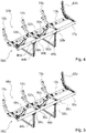
- FIG 4 shows a second embodiment of an aircraft seat stand device according to the invention.
- the aircraft seat stand device is part of an aircraft seat row 56b which is only partially shown.
- the aircraft seat row 56b comprises three aircraft seats 58b.
- the aircraft seat stand device comprises a first carrier profile 10b.
- the first carrier profile 10b is designed as a front cross tube.
- the aircraft seat stand device further comprises a second carrier profile 12b.
- the second support profile 12b is designed as a rear cross tube.
- the carrier profiles 10b, 12b are formed from a light metal.
- the carrier profiles 10b, 12b are formed from an aluminum. In principle, it is also conceivable for the carrier profiles 10b, 12b to be formed from another light material, such as, for example, from a magnesium or titanium.
- the aircraft seat stand device comprises four first aircraft seat elements 14b, 16b, 18b, 42b.
- the first aircraft seat elements 14b, 16b, 18b, 42b are each designed as a seat divider.
- the first aircraft seat elements 14b, 16b, 18b, 42b designed as seat dividers each delimit a seating area of an aircraft seat 58b.
- the first aircraft seat elements 14b, 16b, 18b, 42b designed as seat dividers are essentially of the same design as those of the first exemplary embodiment from FIGS Figures 1 to 3 .
- the aircraft seat stand device comprises four second aircraft seat elements 44b, 46b, 48b, 50b.
- the second aircraft seat elements 44b, 46b, 48b, 50b are each designed as a seat base.
- the second aircraft seat elements 44b, 46b, 48b, 50b designed as seat feet are provided for the aircraft seat support device and thus the aircraft seat row 56b to stand on the level of the insurgent.
- the second aircraft seat elements 44b, 46b, 48b, 50b are configured essentially the same as in the first exemplary embodiment from FIGS Figures 1 to 3 .
- the aircraft seat stand device comprises two first intermediate elements 36b, 38b and two second intermediate elements 40b, 96b.
- the intermediate elements 36b, 38b, 40b, 96b are designed as tubular elements, as in the first exemplary embodiment.
- only one aircraft seat element 14b, 16b, 44b, 46b is coupled to the first and second intermediate elements 36b, 38b, 40b, 96b.
- An embodiment of the two first intermediate elements 36b, 38b and an embodiment of the two second intermediate elements 40b, 96b and a connection of the corresponding first aircraft seat element 14b, 16b or the corresponding second aircraft seat element 44b, 46b to the corresponding intermediate element 36b, 38b, 40b, 96b are identical , which is why only a first intermediate element 36b and a second intermediate element 40b and the connection of the corresponding first aircraft seat element 14b, 16b or the corresponding second aircraft seat element 44b, 46b to the corresponding intermediate element 36b, 38b, 40b, 96b is described below. A description of the corresponding other intermediate element 38b, 96b can be derived from this.
- the first intermediate element 36b is provided for connecting the first aircraft seat element 14b to the carrier profile 10b.
- the first intermediate element 36b has a connection block 52b.
- One connection bracket 52b is designed like the corresponding connection bracket for connecting the first aircraft seat element from the first exemplary embodiment of FIG Figures 1 to 3 .
- the first aircraft seat element 14b is connected to the first intermediate element 36b via a screw connection and is thus coupled to the first carrier profile 10b.
- the first intermediate element 36b like the intermediate elements from the first exemplary embodiment, is connected to the carrier profile by means of an adhesive connection.
- the second intermediate element 40b is provided for connecting the second aircraft seat element 44b to the carrier profile 10b.
- the second intermediate element 40b has a connection bracket 54b.
- One connection bracket 54b is designed like the corresponding connection bracket for connecting the second aircraft seat element from the first exemplary embodiment of FIG Figures 1 to 3 .
- the second aircraft seat element 44b is connected in a fully assembled state via a screw connection to the second intermediate element 40b and thus coupled to the first carrier profile 10b.
- the first intermediate element 40b like the intermediate elements from the first exemplary embodiment, is connected to the carrier profile by means of an adhesive connection.
- the second intermediate element 40b is arranged at a distance from the first intermediate element 36b.
- the first intermediate element 36b and the second intermediate element 40b are independent of one another. It is fundamentally conceivable that the two intermediate elements 36b, 40b are connected to the carrier profile 10b with adhesive connections of different strengths, so that they can be rotated to the carrier profile 10b from loads of different magnitudes.
- FIG. 5 shows a third embodiment of an aircraft seat stand device according to the invention.
- the aircraft seat stand device is part of an aircraft seat row 56c which is only partially shown.
- the aircraft seat row 56c comprises three aircraft seats 58c.
- the aircraft seat stand device comprises a first carrier profile 10c.
- the first carrier profile 10c is designed as a front cross tube.
- the aircraft seat stand device further comprises a second carrier profile 12c.
- the second support profile 12c is designed as a rear cross tube.
- the carrier profiles 10c, 12c are formed from a light metal.
- the aircraft seat stand device comprises four first aircraft seat elements 14c, 16c, 18c, 42c.
- the first aircraft seat elements 14c, 16c, 18c, 42c are each designed as a seat divider.
- the first aircraft seat elements 14c, 16c, 18c, 42c designed as seat dividers each delimit a seating area of an aircraft seat 58c.
- the first aircraft seat elements 14c, 16c, 18c, 42c, which are designed as seat dividers, are essentially of the same design as those of the first exemplary embodiment from FIGS Figures 1 to 3 .
- the aircraft seat stand device comprises four second aircraft seat elements 44c, 46c, 48c, 50c.
- the second aircraft seat elements 44c, 46c, 48c, 50c are each designed as a seat base.
- the second aircraft seat elements 44c, 46c, 48c, 50c which are designed as seat feet, are intended to stand the aircraft seat stand device and thus the aircraft seat row 56c on the stand level.
- the second aircraft seat elements 44c, 46c, 48c, 50c are configured essentially the same as in the first exemplary embodiment from FIGS Figures 1 to 3 .
- the aircraft seat stand device comprises two first intermediate elements 36c, 38c.
- the two first intermediate elements 36c, 38c are equivalent to the two first intermediate elements from the second exemplary embodiment in FIG Figure 4 educated.
- the two first intermediate elements 36c, 38c are provided in each case to connect a first aircraft seat element 14c, 16c designed as a seat divider to the carrier profile 10c.
- a first aircraft seat element 14c, 16c which is designed as a seat divider, is coupled to the corresponding intermediate element 36c, 38c via a connection bracket 52c.
- the second aircraft seat elements 44c, 46c designed as a seat foot are directly coupled to the carrier profile 10c.
- the carrier profile 10c each forms a connection bracket 86c, 88c, via which the second aircraft seat elements 44c, 46c are firmly connected to the carrier profile 10c.
- the second aircraft seat elements 44c, 46c, which are designed as seat bases are connected to the carrier profile 10c in a loop, as is known from the prior art.
- first aircraft seat elements 14c, 16c and the second aircraft seat elements 44c, 46c are carried out in the opposite way to that described above.
- the first aircraft seat elements 14c, 16c which are designed as seat dividers, would be directly and rigidly connected to the carrier profile 10c via a loop or a connection bracket formed by the carrier profile 10c, and the second aircraft seat elements 44c, 46c, which were designed as seat feet, would be connected to the carrier profile 10c via two intermediate elements, and thereby rotatably arranged to the carrier profile 10c in at least one crash / deformation case.
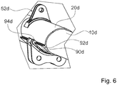
- Figure 6 shows a fourth embodiment of an aircraft seat stand device according to the invention.
- the aircraft seat stand device is part of an only partially shown row of aircraft seats 56d.
- the aircraft seat row 56d comprises three aircraft seats 58d.
- the aircraft seat stand device comprises a first carrier profile 10d.
- the first carrier profile 10d is designed as a front cross tube.
- the aircraft seat stand device further comprises a second carrier profile, which is not shown in detail.
- the carrier profiles are made of a light metal.
- the aircraft seat device Like the other exemplary embodiments, it has first and second aircraft seat elements, which are not shown in more detail here.
- the aircraft seat stand device equivalent to the first exemplary embodiment, comprises a first intermediate element 20d and a second intermediate element, only the first intermediate element 20d being shown and described below.
- the second intermediate element not shown, is equivalent.
- the intermediate element 20d is partially designed differently. Equivalent to the first exemplary embodiment, the intermediate element 20d has a first connection bracket 52d for connecting a first aircraft seat element, which is connected to the intermediate element 20d by means of an adhesive connection.
- the first connection block 52d is of the same design as the corresponding connection block of the first exemplary embodiment.
- the intermediate element 20d has a second connection bracket 54d, which differs from that of the first exemplary embodiment.
- the second connection bracket 54d is connected to the intermediate element 20d via an adhesive connection and a positive connection. In principle, it would also be conceivable that the second connection bracket 54d is only connected to the second intermediate element 20d via a positive connection.
- the intermediate element 20d forms a form-locking element 90d for the positive connection of the connecting block 54d.
- the form-locking element 90d of the intermediate element 20d is designed as an elevation with an undercut 92d.
- the connection bracket 54d forms a form-fitting element 94d which corresponds to the form-fitting element 90d of the intermediate element 20d.
- the form-locking element 94d of the connection bracket 54d is designed as a hook.
- the form-locking element 94d designed as a hook engages in the form-fitting element 90d of the intermediate element 20d in an assembled state.
- This enables a particularly strong and rigid connection between the intermediate element 20d and the second connection bracket 54d to be achieved.
- the second aircraft seat element which is designed as a seat foot, can be connected to the intermediate element 20d in a particularly firm and secure manner and thereby connected to the carrier profile 10d.
- the adhesive connection between the intermediate element 20d and the second connecting block 54d is advantageously reinforced by the positive connection of the positive locking element 94d of the connecting block 54d and the positive locking element 90d of the intermediate element 20d.
Landscapes
- Engineering & Computer Science (AREA)
- Aviation & Aerospace Engineering (AREA)
- Seats For Vehicles (AREA)
- Connection Of Plates (AREA)
- Tires In General (AREA)
Description
- Die Erfindung betrifft eine Flugzeugsitzaufständervorrichtung nach dem Oberbegriff des Patentanspruchs 1.
- Es ist bereits eine Flugzeugsitzaufständervorrichtung mit zumindest einem Trägerprofil, mit zumindest einem Flugzeugsitzelement und mit zumindest einem Zwischenelement, das das zumindest eine Trägerprofil zumindest im Wesentlichen umschließt und mit dem zumindest einen Flugzeugsitzelement gekoppelt ist, vorgeschlagen worden. Dokument
EP0423348 offenbart eine Flugzeugsitzaufständervorrichtung mit zumindest einem Trägerprofil, mit zumindest einem als Sitzteiler oder als Sitzfuß ausgebildeten Flugzeugsitzelement und mit zumindest einem Zwischenelement das das zumindest eine Trägerprofil zumindest im Wesentlichen umschließt und mit dem zumindest einen Flugzeugsitzelement gekoppelt ist, das Zwischenelement ist in einer Axialrichtung zu dem Trägerprofil, auf dem es angeordnet ist, fixiert, wobei das Zwischenelement zumindest in einem Crashfall/ Verformungsfall drehbar zu dem Trägerprofil angeordnet ist, wodurch Torsionsbelastungen auf das Trägerprofil verhindert bzw. minimiert werden. - Die Aufgabe der Erfindung besteht insbesondere darin, eine gattungsgemäße Vorrichtung mit verbesserten Eigenschaften hinsichtlich eines Gewichts und einer Belastbarkeit bereitzustellen. Die Aufgabe wird erfindungsgemäß durch die Merkmale des Patentanspruchs 1 gelöst, während vorteilhafte Ausgestaltungen und Weiterbildungen der Erfindung den Unteransprüchen entnommen werden können.
- Die Erfindung geht aus von einer Flugzeugsitzaufständervorrichtung mit zumindest einem Trägerprofil, mit zumindest einem Flugzeugsitzelement und mit zumindest einem Zwischenelement, das das zumindest eine Trägerprofil zumindest im Wesentlichen umschließt und mit dem zumindest einen Flugzeugsitzelement gekoppelt ist.
- Es wird vorgeschlagen, dass das Zwischenelement zumindest in einem Crashfall/Verformungsfall drehbar zu dem Trägerprofil angeordnet ist. Unter einer "Flugzeugsitzaufständervorrichtung" soll dabei insbesondere eine Vorrichtung verstanden werden, die einen Teil eines Flugzeugsitzes ausbildet, insbesondere einen Teil, mittels dessen der Flugzeugsitz auf einem Kabinenboden aufgeständert ist. Dabei ist die Flugzeugsitzaufständervorrichtung dazu vorgesehen, während eines Betriebs in den Flugzeugsitz eingeleitete Kräfte, wie beispielsweise eine Gewichtskraft einer auf dem Flugzeugsitz sitzenden Person, in den Kabinenboden abzuleiten. Unter einem "Trägerprofil" soll dabei insbesondere ein Element eines Flugzeugsitzes, insbesondere ein Teil eines Rahmens des Flugzeugsitzes, verstanden werden, wobei das Trägerprofil vorzugsweise als ein Querrohr ausgebildet ist, das parallel zu einer Querrichtung des Sitzes verläuft. Das Trägerprofil ist dabei vorzugsweise ein Teil von mehreren, nebeneinander in einer Flugzeugsitzreihe angeordneten Flugzeugsitzen. Unter einem "Flugzeugsitzelement" soll dabei insbesondere ein Teil des Flugzeugsitzes verstanden werden, das einen tragenden Teil des Flugzeugsitzes ausbildet. Dabei überträgt ein Sitzelement während eines Betriebs auftretende Kräfte und leitet diese weiter. Dabei ist das Flugzeugsitzelement vorzugsweise als ein Sitzteiler oder ein Sitzfuß ausgebildet. Unter einem "Zwischenelement" soll dabei insbesondere ein Element verstanden werden, das zwischen zwei Elementen, insbesondere zwischen zumindest einem Flugzeugsitzelement und dem Trägerprofil, angeordnet ist, wobei diese beiden Elemente über das Zwischenelement miteinander gekoppelt sind. Unter "zumindest im Wesentlichen umschließen" soll dabei insbesondere verstanden werden, dass das Zwischenelement das Trägerprofil zumindest zu mehr als 180 Grad, vorzugsweise zu mehr als 270 Grad und in einer besonders vorteilhaften Ausgestaltung vollständig umschließt. Unter der Wendung, dass zwei Elemente miteinander "gekoppelt" sind, soll dabei insbesondere verstanden werden, dass die beiden Elemente, wie insbesondere das Zwischenelement und das Flugzeugsitzelement, fest miteinander verbunden sind, also fest zueinander positioniert sind, wobei die beiden Elemente dabei starr oder aber auch gelenkig miteinander verbunden sein können. Dabei weist eines der Elemente vorzugsweise einen Anbindungsbock auf, über den das andere Element an das eine Element angebunden ist. Grundsätzlich ist es aber auch denkbar, dass die beiden Elemente direkt miteinander gekoppelt sind, beispielsweise durch eine Klebeverbindung oder eine Schweißverbindung oder eine andere, dem Fachmann als sinnvoll erscheinende stoffschlüssige Verbindung. Unter einem "Crashfall" soll dabei insbesondere ein Überlastfall verstanden werden, also ein Betriebszustand, in dem Kräfte auf die Flugzeugsitzaufständervorrichtung und/oder den Flugzeugsitz, dessen Teil die Flugzeugsitzaufständervorrichtung ist, wirken, die größer sind als Kräfte, die durch eine normale Belastung bei einem normalen Flugbetrieb entstehen. Dadurch kann das Flugzeugsitzelement über das Zwischenelement besonders vorteilhaft und einfach angebunden werden und Kräfte können in einem Crashfall besonders einfach über das Zwischenelement abgeleitet werden, ohne das Trägerprofil zusätzlich auf Torsion zu belasten, wodurch insbesondere das Trägerprofil mit einem besonders vorteilhaften geringen Gewicht ausgebildet werden kann.
- Weiter wird vorgeschlagen, dass die Flugzeugsitzaufständervorrichtung zumindest ein weiteres Flugzeugsitzelement aufweist, das mit dem Zwischenelement gekoppelt ist. Dadurch können die zwei Flugzeugsitzelemente besonders vorteilhaft miteinander gekoppelt werden und Kräfte zwischen den beiden Flugzeugsitzelementen übertragen werden.
- Ferner wird vorgeschlagen, dass das Flugzeugsitzelement als ein Sitzteiler ausgebildet ist. Unter einem "Sitzteiler" soll insbesondere ein Bauteil einer Flugzeugsitzreihe mit zumindest zwei seitlich nebeneinander angeordneten Flugzeugsitzen verstanden werden, das bezüglich einer vertikal zu einer Aufständerebene der Flugzeugsitzreihe ausgerichteten Vertikalrichtung zumindest im Wesentlichen oberhalb zumindest eines Trägerprofils, insbesondere eines Single Beams und/oder eines Querrohrs, angeordnet ist. Insbesondere ist der Sitzteiler ein starr ausgebildetes Bauteil der Flugzeugsitzreihe. Vorzugsweise ist der Sitzteiler zumindest im Wesentlichen bezüglich der Vertikalrichtung oberhalb eines Sitzbodens eines jeweiligen Flugzeugsitzes der zumindest zwei seitlich nebeneinander angeordneten Flugzeugsitze der Flugzeugsitzreihe angeordnet. Der Sitzteiler ist insbesondere dazu vorgesehen, eine Armauflageeinheit zu lagern. Vorzugsweise ist der Sitzteiler dazu vorgesehen, eine Gurtanbindung zu ermöglichen. Vorzugsweise bildet der Sitzteiler eine seitliche Begrenzung zumindest eines der zumindest zwei seitlich nebeneinander angeordneten Flugzeugsitze, wobei der Sitzteiler gangseitig und/oder bordseitig angeordnet sein kann und/oder eine Abgrenzung zwischen zwei seitlich nebeneinander angeordneten Flugzeugsitzen der zumindest zwei Flugzeugsitze ausbildet. Dadurch kann das Flugzeugsitzelement besonders vorteilhaft ausgebildet werden.
- Es wird weiterhin vorgeschlagen, dass das Flugzeugsitzelement als ein Sitzfuß ausgebildet ist. Unter einem "Sitzfuß" soll dabei insbesondere ein Element verstanden werden, das den Flugzeugsitz mit einem Kabinenboden verbindet, auf dem der Flugzeugsitz, dessen Teil die Flugzeugsitzaufständervorrichtung ist, aufgeständert ist, wobei der Sitzfuß an einem unteren Ende dabei vorzugsweise mittels eines Anbindungselements mit dem Kabinenboden verbunden und an einem oberen Ende mit dem Trägerprofil gekoppelt ist. Dadurch kann der Sitzfuß des Flugzeugsitzes besonders vorteilhaft an das Trägerprofil angebunden werden.
- Zudem wird vorgeschlagen, dass das Zwischenelement zumindest einen Anbindungsbock aufweist, über den das Flugzeugsitzelement mit dem Zwischenelement gekoppelt ist. Unter einem "Anbindungsbock" soll dabei insbesondere ein Element verstanden werden, das zumindest eine Aufnahme zur Befestigung eines weiteren Elements, wie insbesondere des Flugzeugsitzelements, aufweist. Dadurch kann das Flugzeugsitzelement besonders einfach und vorteilhaft mit dem Zwischenelement verbunden werden.
- Weiterhin wird vorgeschlagen, dass der Anbindungsbock stoffschlüssig mit dem Zwischenelement gekoppelt ist. Unter "stoffschlüssig gekoppelt" soll insbesondere verstanden werden, dass Masseteile der zu koppelnden Elemente durch atomare oder molekulare Kräfte zusammengehalten werden, wie beispielsweise durch Löten, Schweißen, Kleben und/oder Vulkanisieren. Dadurch kann der Anbindungsbock besonders einfach kostengünstig und sicher mit dem Zwischenelement gekoppelt werden.
- Ferner wird vorgeschlagen, dass der Anbindungsbock in einem Anbindungsbereich mit dem Zwischenelement eine Erstreckung in Umfangsrichtung aufweist, die kleiner ist als 180 Grad. Unter einem "Anbindungsbereich" soll dabei insbesondere ein Bereich verstanden werden, in dem der Anbindungsbock mit dem Zwischenelement verbunden ist. Dadurch kann der Anbindungsbock besonders vorteilhaft und platzsparend ausgebildet werden, wobei insbesondere vorteilhaft zumindest zwei Anbindungsböcke in einem gleichen Umfangsbereich angeordnet werden können. Dadurch können an den Anbindungsböcken angebundene Elemente, wie insbesondere Flugzeugsitzelemente, besonders vorteilhaft in einer Ebene an das Zwischenelement angebunden werden.
- Es wird zudem vorgeschlagen, dass das zumindest eine Zwischenelement zumindest in einer Axialrichtung zu dem Trägerprofil fixiert ist. Unter einer "Axialrichtung" soll dabei insbesondere eine Richtung verstanden werden, die der Haupterstreckungsrichtung des Trägerprofils entspricht. Die Axialrichtung ist dabei vorzugsweise quer zu einer Sitzrichtung ausgerichtet. So können das Zwischenelement und dadurch die an dem Zwischenelement angebundenen Flugzeugsitzelemente für einen Betrieb vorteilhaft positioniert werden.
- Weiter wird vorgeschlagen, dass das Zwischenelement zumindest in einem Betriebszustand drehfest zu dem Trägerprofil angeordnet ist. Unter "drehfest" soll dabei insbesondere verstanden werden, dass das Zwischenelement nicht zu dem Trägerprofil drehbar ist.
- Dadurch kann das Zwischenelement für einen Normalbetriebszustand besonders vorteilhaft mit dem Trägerprofil gekoppelt werden.
- Weiterhin wird vorgeschlagen, dass das Zwischenelement zumindest in einem Betriebszustand mittels einer Klebeverbindung fest mit dem Trägerprofil verbunden ist. Dadurch kann vorteilhaft das Zwischenelement besonders einfach und kostengünstig mit dem Trägerprofil verbunden werden.
- Ferner wird vorgeschlagen, dass das Trägerprofil zumindest im Wesentlichen aus einem Leichtmetall und/oder einem Faserverbundwerkstoff gebildet ist. Unter "zumindest im Wesentlichen aus einem Leichtmetall gebildet", soll dabei insbesondere verstanden werden, dass das Trägerprofil zumindest zu 60 %, vorzugsweise zu mehr als 80 % und in einer besonders vorteilhaften Ausgestaltung komplett aus einem Leichtmetall gebildet ist. Unter einem Leichtmetall soll dabei insbesondere ein Metall mit einer Dichte kleiner als 5 g/cm3 verstanden werden, wie insbesondere ein Aluminium, Titan oder Magnesium. Dabei können andere Flugzeugsitzelemente, wie beispielsweise ein Sitzteiler oder ein Sitzfuß, ebenfalls aus diesen Materialien bestehen. Dadurch kann das Trägerprofil besonders leicht ausgebildet werden.
- Es wird weiter vorgeschlagen, dass die Flugzeugsitzaufständervorrichtung zumindest ein zweites Zwischenelement aufweist, wobei jeweils ein Flugzeugsitzelement mit einem der beiden Zwischenelemente gekoppelt ist. Unter einem weiteren "Zwischenelement" soll dabei insbesondere ein zusätzliches, von dem einen Zwischenelement unterschiedliches und getrennt ausgebildetes Zwischenelement verstanden werden. Dadurch können die beiden Flugzeugsitzelemente besonders vorteilhaft über jeweils ein separates Zwischenelement mit dem Trägerprofil gekoppelt werden.
- Außerdem wird vorgeschlagen, dass die Flugzeugsitzaufständervorrichtung zumindest ein weiteres Flugzeugsitzelement aufweist, das direkt mit dem Trägerprofil gekoppelt ist.
- Unter "gekoppelt" soll dabei insbesondere fest miteinander verbunden verstanden werden, wobei das Flugzeugsitzelement dabei vorzugsweise starr mit dem Trägerprofil verbunden ist. Dadurch kann das eine Flugzeugsitzelement besonders vorteilhaft mit dem Trägerprofil gekoppelt werden.
- Die erfindungsgemäße Flugzeugsitzaufständervorrichtung soll hierbei nicht auf die oben beschriebene Anwendung und Ausführungsform beschränkt sein. Insbesondere kann die erfindungsgemäße Flugzeugsitzaufständervorrichtung zu einer Erfüllung einer hierin beschriebenen Funktionsweise eine von einer hierin genannten Anzahl von einzelnen Elementen, Bauteilen und Einheiten abweichende Anzahl aufweisen.
- Weitere Vorteile ergeben sich aus der folgenden Zeichnungsbeschreibung. In den Zeichnungen sind vier Ausführungsbeispiele der Erfindung dargestellt. Die Zeichnungen, die Beschreibung und die Ansprüche enthalten zahlreiche Merkmale in Kombination. Der Fachmann wird die Merkmale zweckmäßigerweise auch einzeln betrachten und zu sinnvollen weiteren Kombinationen zusammenfassen.
- Es zeigen:
- Fig. 1
- eine schematische Darstellung einer erfindungsgemäßen Flugzeugsitzaufständervorrichtung in einem ersten Ausführungsbeispiel,
- Fig. 2
- eine Detailansicht eines Trägerprofils, eines Zwischenelements und von an das Zwischenelement angebundenen Flugzeugsitzelementen der erfindungsgemäßen Flugzeugsitzaufständervorrichtung,
- Fig. 3
- eine Schnittansicht durch das Trägerprofil und das Zwischenelement,
- Fig. 4
- eine schematische Darstellung einer erfindungsgemäßen Flugzeugsitzaufständervorrichtung in einem zweiten Ausführungsbeispiel,
- Fig. 5
- eine schematische Darstellung einer erfindungsgemäßen Flugzeugsitzaufständervorrichtung in einem dritten Ausführungsbeispiel und
- Fig. 6
- eine schematische Detailansicht eines Trägerprofils, eines Zwischenelements und dessen Anbindungsböcke einer erfindungsgemäßen Flugzeugsitzaufständervorrichtung in einem vierten Ausführungsbeispiel.
- Die
Figuren 1 bis 3 zeigen ein erstes Ausführungsbeispiel einer erfindungsgemäßen Flugzeugsitzaufständervorrichtung. Die Flugzeugsitzaufständervorrichtung ist Teil einer lediglich teilweise dargestellten Flugzeugsitzreihe 56a. Die Flugzeugsitzreihe 56a umfasst dabei drei Flugzeugsitze 58a. Grundsätzlich ist es auch denkbar, dass die Flugzeugsitzreihe 56a eine andere Anzahl, beispielsweise lediglich einen, zwei oder vier Flugzeugsitze 58a umfasst. Die Flugzeugsitze 58a sind dazu vorgesehen, dass Fluggäste während eines Flugs auf ihnen Platz nehmen können. Dabei weisen die Flugzeugsitze 58a jeweils einen nicht näher dargestellten Sitzboden und eine nicht näher dargestellte Rückenlehne auf. Des Weiteren ist jeder Flugzeugsitz 58a seitlich von jeweils einer nicht näher dargestellten Armlehne begrenzt. Dabei weisen zwei direkt benachbarte Flugzeugsitze 58a jeweils eine gemeinsame Armlehne auf. Die Flugzeugsitze 58a sind dazu vorgesehen, auf einer Aufständerebene aufgeständert zu werden. Die Aufständerebene wird dabei von einem Kabinenboden eines Flugzeugs ausgebildet. Mittels der Flugzeugsitzaufständervorrichtung sind die Flugzeugsitze 58a in einem montierten Zustand auf dem Kabinenboden aufgeständert. - Die Flugzeugsitzaufständervorrichtung umfasst ein erstes Trägerprofil 10a. Das erste Trägerprofil 10a ist als ein vorderes Querrohr ausgebildet. Die Flugzeugsitzaufständervorrichtung umfasst weiter ein zweites Trägerprofil 12a. Das zweite Trägerprofil 12a ist als ein hinteres Querrohr ausgebildet. Die beiden Trägerprofile 10a, 12a sind beabstandet zueinander angeordnet und verlaufen parallel zueinander. Das als vorderes Querrohr ausgebildete Trägerprofil 10a ist dabei in einem vorderen Bereich der Flugzeugsitze 58a angeordnet. Das als hinteres Querrohr ausgebildete zweite Trägerprofil 12a ist in einem hinteren Bereich der Flugzeugsitze 58a angeordnet. Die Trägerprofile 10a, 12a erstrecken sich dabei in einer Querrichtung zu den Flugzeugsitzen 58a. Die Querrichtung der Flugzeugsitze 58a ist dabei in einem rechten Winkel zu einer Sitzrichtung ausgerichtet.
- Die beiden als Querrohre ausgebildeten Trägerprofile 10a, 12a sind im Wesentlichen gleich ausgebildet, weswegen im Folgenden lediglich das erste Trägerprofil 10a, das als vorderes Querrohr ausgebildet ist, näher beschrieben wird. Eine Beschreibung des ersten Trägerprofils 10a kann dabei zur Erläuterung des zweiten Trägerprofils 12a, das als hinteres Querrohr ausgebildet ist, herangezogen werden. Das als Querrohr ausgebildete Trägerprofil 10a ist rohrförmig ausgebildet. Das Trägerprofil 10a weist einen Querschnitt auf, der einen Ring ausbildet. Dabei ist das Trägerprofil 10a dünnwandig ausgebildet. Das Trägerprofil 10a ist aus einem Faserverbundwerkstoff gebildet. Grundsätzlich ist es auch denkbar, dass das Trägerprofil 10a aus einem Leichtmetall, wie beispielsweise einem Aluminium oder Magnesium, gebildet ist.
- Die Flugzeugsitzaufständervorrichtung umfasst vier erste Flugzeugsitzelemente 14a, 16a, 18a, 42a. Die ersten Flugzeugsitzelemente 14a, 16a, 18a, 42a sind jeweils als ein Sitzteiler ausgebildet. Die als Sitzteiler ausgebildeten ersten Flugzeugsitzelemente 14a, 16a, 18a, 42a begrenzen jeweils einen Sitzbereich eines Flugzeugsitzes 58a. Dabei begrenzen jeweils zwei benachbarte, als Sitzteiler ausgebildete Flugzeugsitzelemente 14a, 16a, 18a, 42a einen Flugzeugsitz 58a der Flugzeugsitzreihe 56a. Die zwei außen liegenden, als Sitzteiler ausgebildeten Flugzeugsitzelemente 18a, 42a begrenzen die Flugzeugsitzreihe 56a nach außen. Die Flugzeugsitzelemente 14a, 16a, 18a, 42a sind L-förmig ausgebildet und erstrecken sich in einem montierten Zustand von dem als vorderes Querrohr ausgebildeten ersten Trägerprofil 10a zu dem als hinteres Querrohr ausgebildeten zweiten Trägerprofil 12a. In montiertem Zustand erstrecken sich die als Sitzteiler ausgebildeten Flugzeugsitzelemente 14a, 16a, 18a, 42a von dem als vorderes Querrohr ausgebildeten ersten Trägerprofil 10a bis hinter das als hinteres Querrohr ausgebildete zweite Trägerprofil 12a. In einem Bereich hinter dem als hinteres Querrohr ausgebildeten zweiten Trägerprofil 12a weisen die als Sitzteiler ausgebildeten ersten Flugzeugsitzelemente 14a, 16a, 18a, 42a einen Knick auf, ab dem sich die Flugzeugsitzelemente 14a, 16a, 18a, 42a von den Trägerprofilen 10a, 12a nach oben, von der Aufständerebene weg erstrecken. Dabei sind die als Sitzteiler ausgebildeten ersten Flugzeugsitzelemente 14a, 16a, 18a, 42a jeweils mit dem als hinteres Querrohr ausgebildeten Trägerprofil 12a gekoppelt. An einem vorderen Ende der als Sitzteiler ausgebildeten ersten Flugzeugsitzelemente 14a, 16a, 18a, 42a sind diese jeweils mit dem als vorderes Querrohr ausgebildeten Trägerprofil 10a gekoppelt. Dazu weisen die als Sitzteiler ausgebildeten ersten Flugzeugsitzelemente 14a, 16a, 18a, 42a an dem vorderen Ende jeweils eine Aufnahme 60a auf. Die Aufnahme 60a ist dabei von einem Durchgangsloch gebildet. Die als Sitzteiler ausgebildeten Flugzeugsitzelemente 14a, 16a, 18a, 42a sind dazu vorgesehen, dass weitere Bauteile der Flugzeugsitze 58a bzw. der Flugzeugsitzreihe 56a, wie insbesondere Armlehnen und/oder Rückenlehnen, angebracht werden. Die als Sitzteiler ausgebildeten ersten Flugzeugsitzelemente 14a, 16a, 18a, 42a sind aus einem Leichtmetall, wie insbesondere einem Aluminium, gebildet. Dabei sind die äußeren zwei, als Sitzteiler ausgebildeten ersten Flugzeugsitzelemente 18a, 42a anders ausgebildet als die inneren beiden, als Sitzteiler ausgebildeten ersten Flugzeugsitzelemente 14a, 16a. Grundsätzlich ist es auch denkbar, dass die Flugzeugsitzelemente 14a, 16a, 18a, 42a alle gleich und/oder aus einem anderen Material, wie beispielsweise einem Faserverbundwerkstoff, ausgebildet sind. Je nachdem, wie viele Flugzeugsitze 58a in der Flugzeugsitzreihe 56a vorhanden sind, kann es grundsätzlich auch sein, dass die Flugzeugsitzaufständervorrichtung eine andere Anzahl von als Sitzteiler ausgebildeten Flugzeugsitzelementen 14a, 16a, 18a, 42a aufweist.
- Die Flugzeugsitzaufständervorrichtung umfasst vier zweite Flugzeugsitzelemente 44a, 46a, 48a, 50a. Die zweiten Flugzeugsitzelemente 44a, 46a, 48a, 50a sind dabei jeweils als ein Sitzfuß ausgebildet. Die als Sitzfüße ausgebildeten zweiten Flugzeugsitzelemente 44a, 46a, 48a, 50a sind dazu vorgesehen, die Flugzeugsitzaufständervorrichtung und damit die Flugzeugsitzreihe 56a auf die Aufständerebene aufzuständern. Dabei sind die zwei zweiten Flugzeugsitzelemente 44a, 46a als vordere Sitzfüße und die anderen zwei zweiten Flugzeugsitzelemente 48a, 50a als hintere Sitzfüße ausgebildet. Die als vordere Sitzfüße ausgebildeten zweiten Flugzeugsitzelemente 44a, 46a sind in einem montierten Zustand mit dem als vorderes Querrohr ausgebildeten ersten Trägerprofil 10a gekoppelt. Die als hintere Sitzfüße ausgebildeten zweiten Flugzeugsitzelemente 48a, 50a sind in einem montierten Zustand mit dem als hinteres Querrohr ausgebildeten zweiten Trägerprofil 12a gekoppelt. Dabei sind die zweiten Flugzeugsitzelemente 44a, 46a, 48a, 50a jeweils mit einem oberen Ende mit dem jeweiligen Trägerprofil 10a, 12a gekoppelt. Zur Anbindung an das jeweilige Trägerprofil 10a, 12a weisen die zweiten Flugzeugsitzelemente 44a, 46a, 48a, 50a an einem oberen Ende jeweils eine Aufnahme 62a auf. Die Aufnahmen 62a sind dabei jeweils von zwei Durchgangslöchern gebildet. An einem unteren Ende weisen die als Sitzfüße ausgebildeten zweiten Flugzeugsitzelemente 44a, 46a, 48a, 50a jeweils nicht weiter detailliert dargestellte oder beschriebene Verbindungselemente auf, über die die als Sitzfüße ausgebildeten zweiten Flugzeugsitzelemente 44a, 46a, 48a, 50a mit in den Kabinenboden eingebrachten Verbindungselementen verbunden werden können. Die Verbindungselemente des Kabinenbodens sind dabei vorzugsweise als Anbindungsschienen ausgebildet. Die Verbindungselemente der als Sitzfüße ausgebildeten zweiten Flugzeugsitzelemente 44a, 46a, 48a, 50a sind als Fittinge ausgebildet, die in die als Anbindungsschienen ausgebildeten Verbindungselemente zur Aufständerung der Flugzeugsitzreihe 56a formschlüssig eingreifen. Grundsätzlich ist es auch denkbar, dass die als Sitzfüße ausgebildeten zweiten Flugzeugsitzelemente 44a, 46a, 48a, 50a anders ausgebildete Verbindungselemente aufweisen, die die zweiten Flugzeugsitzelemente 44a, 46a, 48a, 50a auf eine andere Art fest auf einer Aufständerebene befestigen. Die zwei als vordere Sitzfüße ausgebildeten zweiten Flugzeugsitzelemente 44a, 46a sind als im Wesentlichen gerade Profile ausgebildet, die sich in einem montierten Zustand von dem ersten Trägerprofil 10a im Wesentlichen senkrecht nach unten erstrecken. Die zwei als hintere Sitzfüße ausgebildeten zweiten Flugzeugsitzelemente 48a, 50a sind als gekrümmte Profile ausgebildet, die sich von dem zweiten Trägerprofil 12a sowohl nach unten als auch nach hinten, also von dem ersten Trägerprofil 10a weg erstrecken. Dabei ist jeweils eines der als vorderer Sitzfuß ausgebildeten zweiten Flugzeugsitzelemente 44a, 46a parallel zu einem der als hinterer Sitzfuß ausgebildeten zweiten Flugzeugsitzelemente 48a, 50a ausgerichtet. Das als vorderer Sitzfuß ausgebildete zweite Flugzeugsitzelement 44a, 46a und das als hinterer Sitzfuß ausgebildete zweite Flugzeugsitzelement 48a, 50a, die parallel zueinander ausgerichtet sind, sind jeweils mittels einer Verbindungsstange 64a, 66a an einem unteren Ende miteinander verbunden. Grundsätzlich ist es auch denkbar, dass zwei parallel zueinander angeordnete, als Sitzfüße ausgebildete Flugzeugsitzelemente 44a, 46a, 48a, 50a oder alle als Sitzfüße ausgebildeten Flugzeugsitzelemente 44a, 46a, 48a, 50a integral als ein einstückiger Sitzfuß ausgebildet sind.
- Die Flugzeugsitzaufständervorrichtung umfasst ein erstes Zwischenelement 20a und ein zweites Zwischenelement 22a. Die Zwischenelemente 20a, 22a umschließen das erste, als vorderes Querrohr ausgebildete Trägerprofil 10a komplett. Grundsätzlich wäre es auch denkbar, dass die Zwischenelemente 20a, 22a das erste Trägerprofil 10a in Umfangsrichtung nur teilweise umschließen. Die Zwischenelemente 20a, 22a sind dabei als Rohrelemente ausgebildet. Die als Rohrelemente ausgebildeten Zwischenelemente 20a, 22a sind dabei aus einem Faserverbundwerkstoff gebildet. Grundsätzlich ist es auch denkbar, dass die Zwischenelemente 20a, 22a aus einem anderen Material, wie vorzugsweise einem Leichtmetall, wie beispielsweise einem Aluminium, gebildet sind. Das erste Zwischenelement 20a ist mit dem ersten, als Sitzteiler ausgebildeten ersten Flugzeugsitzelement 14a gekoppelt. Außerdem ist das erste Zwischenelement 20a mit dem einen, als vorderer Sitzfuß ausgebildeten zweiten Flugzeugsitzelement 44a verbunden. Das erste Zwischenelement 20a ist zur Anbindung des als Sitzteiler ausgebildeten ersten Flugzeugsitzelements 14a und des als vorderer Sitzfuß ausgebildeten zweiten Flugzeugsitzelements 44a an das als vorderes Querrohr ausgebildete erste Trägerprofil 10a vorgesehen. Über das erste Zwischenelement 20a sind das erste Flugzeugsitzelement 14a und das zweite Flugzeugsitzelement 44a mit dem ersten Trägerprofil 10a verbunden. Das zweite Zwischenelement 22a ist zur Anbindung des anderen ersten, als Sitzteiler ausgebildeten Flugzeugsitzelements 16a und des anderen, als vorderer Sitzfuß ausgebildeten zweiten Flugzeugsitzelements 46a an das als vorderes Querrohr ausgebildete erste Trägerprofil 10a vorgesehen. Über das zweite Zwischenelement 22a sind das erste Flugzeugsitzelement 16a und das zweite Flugzeugsitzelement 46a mit dem ersten Trägerprofil 10a verbunden. Eine Ausgestaltung des ersten Zwischenelements 20a und des zweiten Zwischenelements 22a sowie eine Anbindung des entsprechenden ersten Flugzeugsitzelements 14a, 16a und des entsprechenden zweiten Flugzeugsitzelements 44a, 46a an das entsprechende Zwischenelement 20a, 22a sind identisch, weswegen im Folgenden lediglich das erste Zwischenelement 20a und die Anbindung des entsprechenden ersten Flugzeugsitzelements 14a und des entsprechenden zweiten Flugzeugsitzelements 44a an das Zwischenelement 20a beschrieben werden. Eine Ausgestaltung des zweiten Zwischenelements 22a und eine Anbindung der entsprechenden Flugzeugsitzelemente 16a, 46a an dieses Zwischenelement 22a können dabei der Beschreibung des ersten Zwischenelements 20a entnommen werden.
- Das Zwischenelement 20a umschließt das erste Trägerprofil. Dabei liegt das Zwischenelement 20a mit einer Innenseite auf einer Außenseite des Trägerprofils 10a an. In einem Crashfall/Verformungsfall ist das Zwischenelement 20a drehbar zu dem Trägerprofil 10a angeordnet. In einem Crashfall/Verformungsfall kann sich das Zwischenelement 20a bei einer Krafteinwirkung um das Trägerprofil 10a drehen. Dadurch werden insbesondere Torsionsbelastungen auf das Trägerprofil 10a in einem Crashfall/Verformungsfall verhindert bzw. minimiert.
- Zur Anbindung des ersten Flugzeugsitzelements 14a weist das Zwischenelement 20a einen ersten Anbindungsbock 52a auf. Über den ersten Anbindungsbock 52a ist das erste Flugzeugsitzelement 14a in einem montierten Zustand mit dem Zwischenelement 20a gekoppelt. Der erste Anbindungsbock 52a ist aus einem Kunststoff gebildet. Grundsätzlich ist es auch denkbar, dass der erste Anbindungsbock 52a aus einem anderen Material, wie beispielsweise Aluminium, gebildet ist. Der Anbindungsbock 52a erstreckt sich dabei in einem montierten Zustand in Richtung des ersten Flugzeugsitzelements 14a. Der Anbindungsbock 52a ist dabei stoffschlüssig mit dem Zwischenelement 20a verbunden. An einer ersten Seite weist der Anbindungsbock 52a einen Anbindungsbereich auf, über den der Anbindungsbock 52a mit dem Zwischenelement 20a verbunden ist. Dabei ist der Anbindungsbock 52a in dem Anbindungsbereich über eine Klebeverbindung mit einer Oberfläche des Zwischenelements 20a verbunden. Der Anbindungsbereich weist dabei eine Erstreckung in Umfangsrichtung auf, die kleiner ist als 180 Grad. Der Anbindungsbock 52a nimmt in Umfangsrichtung einen Bereich des Zwischenelements 20a von kleiner als 180 Grad ein. Grundsätzlich ist es auch denkbar, dass der Anbindungsbock 52a einstückig mit dem Zwischenelement 20a ausgebildet ist. An einem zweiten Ende weist der Anbindungsbock 52a eine Aufnahme 68a auf. Die Aufnahme 68a ist zur Anbindung des ersten Flugzeugsitzelements 14a an den Anbindungsbock 52a vorgesehen. Die Aufnahme 68a ist von zwei beabstandet angeordneten Platten 70a, 72a gebildet, die jeweils ein Aufnahmeloch aufweisen, wobei die Aufnahmelöcher in einer Flucht zueinander ausgerichtet sind. Über ein als Schraube ausgebildetes Befestigungselement 74a, das durch die beiden Aufnahmelöcher der Aufnahme 68a geführt ist, und ein als Mutter ausgebildeten Befestigungselement, das mit dem als Schraube ausgebildeten Befestigungselement 74a verbunden ist, ist das erste Flugzeugsitzelement 14a an den Anbindungsbock 52a angebunden. Dazu ist das erste Flugzeugsitzelement 14a mit dem Durchgangsloch seiner Aufnahme 60a fluchtend zwischen den beiden Aufnahmelöchern der Aufnahme 68a des ersten Anbindungsbocks 52a ausgerichtet. Das als Schraube ausgebildete Befestigungselement 74a ist durch die Aufnahmelöcher der Aufnahme 68a des ersten Anbindungsbocks 52a und durch das Durchgangsloch der Aufnahme 60a des ersten Flugzeugsitzelements 14a geführt. Das als Schraube ausgebildete Befestigungselement 74a ist mit dem als Mutter ausgebildeten Befestigungselement in der Aufnahme 68a des ersten Anbindungsbocks 52a und der Aufnahme 60a des ersten Flugzeugsitzelements 14a fixiert. Grundsätzlich ist es auch denkbar, dass die Aufnahme 60a des ersten Anbindungsbocks 52a anders ausgebildet ist und das erste Flugzeugsitzelement 14a mittels einer anderen Befestigungsmethode an den ersten Anbindungsbock 52a angebunden ist. Dabei ist es denkbar, dass das Befestigungselement 74a zur formschlüssigen Anbindung des ersten Flugzeugsitzelements 14a beispielsweise als ein Bolzen oder Stift ausgebildet ist. Grundsätzlich ist es auch denkbar, dass das erste Flugzeugsitzelement 14a über mehrere Befestigungselemente 74a an den Anbindungsbock 52a angebunden ist. Grundsätzlich ist es ebenfalls denkbar, dass das Flugzeugsitzelement 14a über ein anders ausgestaltetes Form- und/oder Kraftschlusselement mit dem Anbindungsbock 52a verbunden ist.
- Zur Anbindung des zweiten Flugzeugsitzelements 44a weist das Zwischenelement 20a einen zweiten Anbindungsbock 54a auf. Über den zweiten Anbindungsbock 54a ist das zweite Flugzeugsitzelement 44a in einem montierten Zustand mit dem Zwischenelement 20a gekoppelt. Der zweite Anbindungsbock 54a ist aus einem Kunststoff gebildet. Grundsätzlich ist es auch denkbar, dass der zweite Anbindungsbock 54a ebenfalls aus einem anderen Material, wie beispielsweise Aluminium, gebildet ist. Der zweite Anbindungsbock 54a erstreckt sich dabei in einem montierten Zustand nach unten in Richtung des zweiten Flugzeugsitzelements 44a. Der zweite Anbindungsbock 54a ist dabei stoffschlüssig mit dem Zwischenelement 20a verbunden. An einer ersten Seite weist der zweite Anbindungsbock 54a einen Anbindungsbereich auf, über den der zweite Anbindungsbock 54a mit dem Zwischenelement 20a verbunden ist. Dabei ist der zweite Anbindungsbock 54a in dem Anbindungsbereich über eine Klebeverbindung mit einer Oberfläche des Zwischenelements 20a verbunden. Der Anbindungsbereich des zweiten Anbindungsbocks 54a weist dabei eine Erstreckung in Umfangsrichtung auf, die kleiner ist als 180 Grad. Der zweite Anbindungsbock 54a ist dabei in einer Axialrichtung zu dem ersten Anbindungsbock 52a verschoben. Durch die Ausgestaltung der Anbindungsbereiche der Anbindungsböcke 52a, 54a, die jeweils eine Erstreckung in Umfangsrichtung von weniger als 180 Grad aufweisen, wäre es auch denkbar, dass der erste Anbindungsbock 52a und der zweite Anbindungsbock 54a in einer gleichen axialen Position auf dem Zwischenelement 20a angeordnet sind. Die beiden Anbindungsböcke 52a, 54a wären dabei in Umfangsrichtung des Zwischenelements 20a hintereinander angeordnet. Dadurch könnten das erste Flugzeugsitzelement 14a und das zweite Flugzeugsitzelement 44a in einer gleichen axialen Position an das Trägerprofil 10a angebracht werden. An einem zweiten Ende weist der zweite Anbindungsbock 54a eine Aufnahme 76a auf. Die Aufnahme 76a ist zur Anbindung des zweiten Flugzeugsitzelements 44a an den zweiten Anbindungsbock 54a vorgesehen. Die Aufnahme 76a ist von zwei beabstandet angeordneten Platten 78a, 80a gebildet, die jeweils zwei Aufnahmelöcher aufweisen, wobei die beiden Aufnahmelöcher in der einen Platte 78a, 80a jeweils in einer Flucht zu einem der Aufnahmelöcher der anderen Platte 78a, 80a ausgerichtet sind. Durch zwei als Schrauben ausgebildete Befestigungselemente 82a, 84a und zwei als Muttern ausgebildete Befestigungselemente ist das zweite Flugzeugsitzelement 44a mit seiner Aufnahme 62a an die Aufnahme 76a des zweiten Anbindungsbocks 54a angebunden. Dadurch ist das als Sitzfuß ausgebildete zweite Flugzeugsitzelement 44a fest mit dem Zwischenelement 20a verbunden. Dabei ist es denkbar, dass der zweite Anbindungsbock 54a wie der erste Anbindungsbock 52a auf eine andere Art und Weise zur Befestigung des Flugzeugsitzelements 44a ausgestaltet sein kann.
- Das Zwischenelement 20a ist in einer Axialrichtung zu dem Trägerprofil 10a, auf dem es angeordnet ist, fixiert. Außerdem ist das Zwischenelement 20a in einem normalen Betriebszustand der Flugzeugsitzaufständervorrichtung drehfest zu dem Trägerprofil 10a angeordnet. Das Zwischenelement 20a ist dabei bis zu einer definierten Maximallast gegen ein Verdrehen gesichert. Das Zwischenelement 20a ist in einem montierten und betriebsbereiten Betriebszustand mittels einer Klebeverbindung mit dem Trägerprofil 10a verbunden. Zwischen einer Außenseite des Trägerprofils 10a und einer Innenseite des Zwischenelements 20a ist eine Klebeschicht angeordnet, die das Trägerprofil 10a und das Zwischenelement 20a über eine adhäsive Verbindung miteinander verbindet. Über die Klebeverbindung ist das Zwischenelement 20a in einem normalen Betriebszustand der Flugzeugsitzaufständervorrichtung axial fixiert. Außerdem ist das Zwischenelement 20a über die Klebeverbindung drehfest auf dem Trägerprofil 10a angeordnet. Das Zwischenelement 20a ist in dem normalen Betriebszustand der Flugzeugsitzaufständervorrichtung fest auf dem Trägerprofil 10a fixiert. Grundsätzlich ist es auch denkbar, dass das Zwischenelement 20a zur axialen und/oder rotatorischen Sicherung auf eine andere form- und/oder kraftschlüssige Weise mit dem Trägerprofil 10a gekoppelt ist, beispielsweise über eine Formschlussverbindung, wie beispielsweise durch einen in das Trägerprofil 10a und das Zwischenelement 20a formschlüssig eingreifenden Stift.
- Wie zuvor beschrieben, ist das Zwischenelement 20a in einem normalen Betriebszustand der Flugzeugsitzaufständervorrichtung drehfest und axial fixiert auf dem Trägerprofil 10a angeordnet. Der normale Betriebszustand ist von einem Betriebszustand gebildet, in dem die Flugzeugsitzreihe 56a, deren Teil die Flugzeugsitzaufständervorrichtung ist, in einem Flugzeug aufgeständert ist. Dabei können Personen auf Flugzeugsitzen 58a der Flugzeugsitzreihe 56a sitzen, wodurch Kräfte über den Sitzboden und die Rückenlehne in den Flugzeugsitz 58a und damit die Flugzeugsitzaufständervorrichtung eingeleitet werden. Kräfte, die in das erste, als Sitzteiler ausgebildete Flugzeugsitzelement 14a eingeleitet werden, werden über das Zwischenelement 20a in das zweite, als Sitzfuß ausgebildete Flugzeugsitzelement 44a eingeleitet. Ein durch die auf das Zwischenelement 20a eingeleiteten Kräfte entstehendes Moment, das auf das Zwischenelement 20a wirkt, wird durch die Verbindung zwischen dem Zwischenelement 20a und dem Trägerprofil 10a gegen das Trägerprofil 10a abgestützt. In einem Crashfall/Verformungsfall, in dem Beschleunigungskräfte auf die Flugzeugsitze 58a der Flugzeugsitzreihe 56a einwirken, die über zugelassene Beschleunigungskräfte hinausgehen, und die Maximallast überstiegen wird, gegen die das Zwischenelement 20a gegen ein Verdrehen gesichert ist, schert die Klebeverbindung zwischen dem Zwischenelement 20a und dem Trägerprofil 10a ab und das Zwischenelement 20a ist zu dem Trägerprofil 10a drehbar. Dadurch kann eine Torsionsbelastung in dem Crashfall/Verformungsfall, die über die Flugzeugsitzelemente 14a, 44a auf das Trägerprofil 10a eingeleitet wird, auf ein Maximum begrenzt werden. Das geschieht dadurch, dass die Klebeverbindung bei einer bestimmten Belastung abschert, sich das Zwischenelement 20a zu dem Trägerprofil 10a drehen kann und so eine Einleitung eines Torsionsmoments von den Flugzeugsitzelementen 14a, 44a über das Zwischenelement 20a in das Trägerprofil 10a verhindert wird. Dadurch kann das Trägerprofil 10a besonders leicht und materialsparend ausgebildet werden, da es für den Crashfall/Verformungsfall nicht gegen Torsionsbelastungen durch die Flugzeugsitzelemente 14a, 44a ausgelegt werden muss.
- Zur Anbindung der ersten Flugzeugsitzelemente 14a, 16a und der zweiten Flugzeugsitzelemente 48a, 50a an das zweite Trägerprofil 12a weist die Flugzeugsitzaufständervorrichtung zwei weitere Zwischenelemente 24a, 26a auf. Die zwei weiteren Zwischenelemente 24a, 26a sind im Wesentlichen gleich ausgebildet wie die Zwischenelemente 20a, 22a zur Anbindung der Flugzeugsitzelemente 14a, 16a an das erste Trägerprofil 10a. Die Flugzeugsitzelemente 14a, 16a sind dabei ebenfalls über nicht näher beschriebene Anbindungsböcke 98a, 100a an die Zwischenelemente 24a, 26a angebunden, wobei wieder jeweils ein erstes Flugzeugsitzelement 14a, 16a und ein zweites Flugzeugsitzelement 48a, 50a an ein Zwischenelement 24a, 26a angebunden sind. Zur Anbindung der äußeren ersten Flugzeugsitzelemente 18a, 42a weist die Flugzeugsitzaufständervorrichtung je Flugzeugsitzelement 18a, 42a jeweils ein Zwischenelement 28a, 32a zur Anbindung an das erste Trägerprofil 10a und jeweils ein Zwischenelement 30a, 34a zur Anbindung an das zweite Trägerprofil 12a auf. Die Zwischenelemente 28a, 30a, 32a, 34a sind äquivalent zu den anderen Zwischenelementen 20a, 22a, 24a, 26a ausgebildet, weisen aber jeweils lediglich einen nicht näher dargestellten Anbindungsbock auf, um das entsprechende Flugzeugsitzelement 18a, 42a an das entsprechende Zwischenelement 28a, 30a, 32a, 34a und dadurch das entsprechende Trägerprofil 10a, 12a anzubinden. Die Zwischenelemente 28a, 30a, 32a, 34a sind äquivalent zu den anderen Zwischenelementen 20a, 22a, 24a, 26a mit den entsprechenden Trägerprofilen 10a, 12a verbunden.
- In
Fig. 4 bis 6 sind drei weitere Ausführungsbeispiele der Erfindung gezeigt. Die nachfolgenden Beschreibungen und die Zeichnungen beschränken sich im Wesentlichen auf die Unterschiede zwischen den Ausführungsbeispielen, wobei bezüglich gleich bezeichneter Bauteile, insbesondere in Bezug auf Bauteile mit gleichen Bezugszeichen, grundsätzlich auch auf die Zeichnungen und/oder die Beschreibung der anderen Ausführungsbeispiele, insbesondere derFig. 1 bis 3 , verwiesen werden kann. Zur Unterscheidung der Ausführungsbeispiele ist der Buchstabe a den Bezugszeichen des Ausführungsbeispiels inFig. 1 bis 3 nachgestellt. In den Ausführungsbeispielen derFig. 4 bis 6 ist der Buchstabe a durch die Buchstaben b bis d ersetzt. -
Figur 4 zeigt ein zweites Ausführungsbeispiel einer erfindungsgemäßen Flugzeugsitzaufständervorrichtung. Die Flugzeugsitzaufständervorrichtung ist Teil einer lediglich teilweise dargestellten Flugzeugsitzreihe 56b. Die Flugzeugsitzreihe 56b umfasst dabei drei Flugzeugsitze 58b. Die Flugzeugsitzaufständervorrichtung umfasst ein erstes Trägerprofil 10b. Das erste Trägerprofil 10b ist als ein vorderes Querrohr ausgebildet. Die Flugzeugsitzaufständervorrichtung umfasst weiter ein zweites Trägerprofil 12b. Das zweite Trägerprofil 12b ist als ein hinteres Querrohr ausgebildet. Die Trägerprofile 10b, 12b sind aus einem Leichtmetall gebildet. Dabei sind die Trägerprofile 10b, 12b aus einem Aluminium gebildet. Grundsätzlich ist es auch denkbar, dass die Trägerprofile 10b, 12b aus einem anderen Leichtmaterial gebildet sind, wie beispielsweise aus einem Magnesium oder Titan. - Die Flugzeugsitzaufständervorrichtung umfasst vier erste Flugzeugsitzelemente 14b, 16b, 18b, 42b. Die ersten Flugzeugsitzelemente 14b, 16b, 18b, 42b sind jeweils als ein Sitzteiler ausgebildet. Die als Sitzteiler ausgebildeten ersten Flugzeugsitzelemente 14b, 16b, 18b, 42b begrenzen jeweils einen Sitzbereich eines Flugzeugsitzes 58b. Die als Sitzteiler ausgebildeten ersten Flugzeugsitzelemente 14b, 16b, 18b, 42b sind dabei im Wesentlichen gleich ausgebildet wie die des ersten Ausführungsbeispiels aus den
Figuren 1 bis 3 . Die Flugzeugsitzaufständervorrichtung umfasst vier zweite Flugzeugsitzelemente 44b, 46b, 48b, 50b. Die zweiten Flugzeugsitzelemente 44b, 46b, 48b, 50b sind dabei jeweils als ein Sitzfuß ausgebildet. Die als Sitzfüße ausgebildeten zweiten Flugzeugsitzelemente 44b, 46b, 48b, 50b sind dazu vorgesehen, die Flugzeugsitzaufständervorrichtung und damit die Flugzeugsitzreihe 56b auf die Aufständerebene aufzuständern. Die zweiten Flugzeugsitzelemente 44b, 46b, 48b, 50b sind dabei im Wesentlichen gleich ausgebildet wie in dem ersten Ausführungsbeispiel aus denFiguren 1 bis 3 . - Die Flugzeugsitzaufständervorrichtung umfasst zwei erste Zwischenelemente 36b, 38b und zwei zweite Zwischenelemente 40b, 96b. Die Zwischenelemente 36b, 38b, 40b, 96b sind dabei wie in dem ersten Ausführungsbeispiel als Rohrelemente ausgebildet. Im Unterschied zu den Zwischenelementen des ersten Ausführungsbeispiels ist mit den ersten und zweiten Zwischenelementen 36b, 38b, 40b, 96b jeweils lediglich ein Flugzeugsitzelement 14b, 16b, 44b, 46b gekoppelt. Eine Ausgestaltung der beiden ersten Zwischenelemente 36b, 38b und eine Ausgestaltung der beiden zweiten Zwischenelemente 40b, 96b sowie eine Anbindung des entsprechenden ersten Flugzeugsitzelements 14b, 16b oder des entsprechenden zweiten Flugzeugsitzelements 44b, 46b an das entsprechende Zwischenelement 36b, 38b, 40b, 96b sind identisch, weswegen im Folgenden lediglich ein erstes Zwischenelement 36b und ein zweites Zwischenelement 40b sowie die Anbindung des entsprechenden ersten Flugzeugsitzelements 14b, 16b bzw. des entsprechenden zweiten Flugzeugsitzelements 44b, 46b an das entsprechende Zwischenelement 36b, 38b, 40b, 96b beschrieben wird. Hieraus kann eine Beschreibung des entsprechenden anderen Zwischenelements 38b, 96b abgeleitet werden.
- Das erste Zwischenelement 36b ist zur Anbindung des ersten Flugzeugsitzelements 14b an das Trägerprofil 10b vorgesehen. Dazu weist das erste Zwischenelement 36b einen Anbindungsbock 52b auf. Der eine Anbindungsbock 52b ist ausgebildet wie der entsprechende Anbindungsbock zur Anbindung des ersten Flugzeugsitzelements aus dem ersten Ausführungsbeispiel der
Figuren 1 bis 3 . Das erste Flugzeugsitzelement 14b ist in einem voll montierten Zustand über eine Schraubenverbindung mit dem ersten Zwischenelement 36b verbunden und damit mit dem ersten Trägerprofil 10b gekoppelt. Das erste Zwischenelement 36b ist dabei wie die Zwischenelemente aus dem ersten Ausführungsbeispiel mittels einer Klebeverbindung mit dem Trägerprofil verbunden. - Das zweite Zwischenelement 40b ist zur Anbindung des zweiten Flugzeugsitzelements 44b an das Trägerprofil 10b vorgesehen. Dazu weist das zweite Zwischenelement 40b einen Anbindungsbock 54b auf. Der eine Anbindungsbock 54b ist ausgebildet wie der entsprechende Anbindungsbock zur Anbindung des zweiten Flugzeugsitzelements aus dem ersten Ausführungsbeispiel der
Figuren 1 bis 3 . Das zweite Flugzeugsitzelement 44b ist in einem voll montierten Zustand über eine Schraubenverbindung mit dem zweiten Zwischenelement 40b verbunden und damit mit dem ersten Trägerprofil 10b gekoppelt. Das erste Zwischenelement 40b ist dabei wie die Zwischenelemente aus dem ersten Ausführungsbeispiel mittels einer Klebeverbindung mit dem Trägerprofil verbunden. Dabei ist das zweite Zwischenelement 40b beabstandet zu dem ersten Zwischenelement 36b angeordnet. Das erste Zwischenelement 36b und das zweite Zwischenelement 40b sind dabei unabhängig voneinander. Dabei ist es grundsätzlich denkbar, dass die beiden Zwischenelemente 36b, 40b mit unterschiedlich starken Klebeverbindungen mit dem Trägerprofil 10b verbunden sind, sodass diese ab unterschiedlich großen Belastungen drehbar zu dem Trägerprofil 10b sind. -
Figur 5 zeigt ein drittes Ausführungsbeispiel einer erfindungsgemäßen Flugzeugsitzaufständervorrichtung. Die Flugzeugsitzaufständervorrichtung ist Teil einer lediglich teilweise dargestellten Flugzeugsitzreihe 56c. Die Flugzeugsitzreihe 56c umfasst dabei drei Flugzeugsitze 58c. Die Flugzeugsitzaufständervorrichtung umfasst ein erstes Trägerprofil 10c. Das erste Trägerprofil 10c ist als ein vorderes Querrohr ausgebildet. Die Flugzeugsitzaufständervorrichtung umfasst weiter ein zweites Trägerprofil 12c. Das zweite Trägerprofil 12c ist als ein hinteres Querrohr ausgebildet. Die Trägerprofile 10c, 12c sind aus einem Leichtmetall gebildet. - Die Flugzeugsitzaufständervorrichtung umfasst vier erste Flugzeugsitzelemente 14c, 16c, 18c, 42c. Die ersten Flugzeugsitzelemente 14c, 16c, 18c, 42c sind jeweils als ein Sitzteiler ausgebildet. Die als Sitzteiler ausgebildeten ersten Flugzeugsitzelemente 14c, 16c, 18c, 42c begrenzen jeweils einen Sitzbereich eines Flugzeugsitzes 58c. Die als Sitzteiler ausgebildeten ersten Flugzeugsitzelemente 14c, 16c, 18c, 42c sind dabei im Wesentlichen gleich ausgebildet wie die des ersten Ausführungsbeispiels aus den
Figuren 1 bis 3 . Die Flugzeugsitzaufständervorrichtung umfasst vier zweite Flugzeugsitzelemente 44c, 46c, 48c, 50c. Die zweiten Flugzeugsitzelemente 44c, 46c, 48c, 50c sind dabei jeweils als ein Sitzfuß ausgebildet. Die als Sitzfüße ausgebildeten zweiten Flugzeugsitzelemente 44c, 46c, 48c, 50c sind dazu vorgesehen, die Flugzeugsitzaufständervorrichtung und damit die Flugzeugsitzreihe 56c auf die Aufständerebene aufzuständern. Die zweiten Flugzeugsitzelemente 44c, 46c, 48c, 50c sind dabei im Wesentlichen gleich ausgebildet wie in dem ersten Ausführungsbeispiel aus denFiguren 1 bis 3 . - Die Flugzeugsitzaufständervorrichtung umfasst zwei erste Zwischenelemente 36c, 38c. Die zwei ersten Zwischenelemente 36c, 38c sind dabei äquivalent zu den zwei ersten Zwischenelementen aus dem zweiten Ausführungsbeispiel der
Figur 4 ausgebildet. Die zwei ersten Zwischenelemente 36c, 38c sind dabei dazu vorgesehen, jeweils ein erstes, als Sitzteiler ausgebildetes Flugzeugsitzelement 14c, 16c an das Trägerprofil 10c anzubinden. Dazu ist jeweils ein als Sitzteiler ausgebildetes erstes Flugzeugsitzelement 14c, 16c über einen Anbindungsbock 52c mit dem entsprechenden Zwischenelement 36c, 38c gekoppelt. - Die als Sitzfuß ausgebildeten zweiten Flugzeugsitzelemente 44c, 46c sind direkt mit dem Trägerprofil 10c gekoppelt. Dazu bildet das Trägerprofil 10c jeweils einen Anbindungsbock 86c, 88c aus, über den die zweiten Flugzeugsitzelemente 44c, 46c fest mit dem Trägerprofil 10c verbunden sind. Dabei entfällt zwischen den zweiten Flugzeugsitzelementen 44c, 46c und dem Trägerprofil 10c ein Zwischenelement, welches in einem Crashfall/Verformungsfall drehbar zu dem Trägerprofil 10c ausgebildet ist. Grundsätzlich ist es dabei auch denkbar, dass die als Sitzfuß ausgebildeten zweiten Flugzeugsitzelemente 44c, 46c, wie aus dem Stand der Technik bekannt, umschlungen an das Trägerprofil 10c angebunden sind.
- Grundsätzlich wäre auch eine Ausgestaltung denkbar, in der eine Anbindung der ersten Flugzeugsitzelemente 14c, 16c und der zweiten Flugzeugsitzelemente 44c, 46c umgekehrt zu der oben beschriebenen ausgeführt ist. Dabei wären die als Sitzteiler ausgebildeten ersten Flugzeugsitzelemente 14c, 16c über eine Umschlingung oder einen von dem Trägerprofil 10c ausgebildeten Anbindungsbock direkt und starr mit dem Trägerprofil 10c verbunden und die als Sitzfüße ausgebildeten zweiten Flugzeugsitzelemente 44c, 46c über zwei Zwischenelemente mit dem Trägerprofil 10c verbunden, und dadurch in zumindest einem Crashfall/Verformungsfall drehbar zu dem Trägerprofil 10c angeordnet.
-
Figur 6 zeigt ein viertes Ausführungsbeispiel einer erfindungsgemäßen Flugzeugsitzaufständervorrichtung. Die Flugzeugsitzaufständervorrichtung ist Teil einer lediglich teilweise dargestellten Flugzeugsitzreihe 56d. Die Flugzeugsitzreihe 56d umfasst dabei drei Flugzeugsitze 58d. Die Flugzeugsitzaufständervorrichtung umfasst ein erstes Trägerprofil 10d. Das erste Trägerprofil 10d ist als ein vorderes Querrohr ausgebildet. Die Flugzeugsitzaufständervorrichtung umfasst weiter ein zweites Trägerprofil, das nicht näher dargestellt ist. Die Trägerprofile sind aus einem Leichtmetall gebildet. Die Flugzeugsitzvorrichtung weist wie die anderen Ausführungsbeispiele erste und zweite Flugzeugsitzelemente auf, die hier nicht näher dargestellt sind. - Die Flugzeugsitzaufständervorrichtung umfasst äquivalent zu dem ersten Ausführungsbeispiel ein erstes Zwischenelement 20d und ein zweites Zwischenelement, wobei lediglich das erste Zwischenelement 20d dargestellt und im Folgenden beschrieben ist. Das zweite, nicht näher dargestellte Zwischenelement ist äquivalent ausgebildet. Das Zwischenelement 20d ist im Unterschied zu dem ersten Ausführungsbeispiel teilweise anders ausgeführt. Äquivalent zu dem ersten Ausführungsbeispiel weist das Zwischenelement 20d zur Anbindung eines ersten Flugzeugsitzelements einen ersten Anbindungsbock 52d auf, der mittels einer Klebeverbindung mit dem Zwischenelement 20d verbunden ist. Der erste Anbindungsbock 52d ist gleich ausgebildet wie der entsprechende Anbindungsbock des ersten Ausführungsbeispiels. Zur Anbindung des als Sitzfuß ausgebildeten zweiten Flugzeugsitzelements weist das Zwischenelement 20d einen zweiten Anbindungsbock 54d auf, der sich von dem des ersten Ausführungsbeispiels unterscheidet. Der zweite Anbindungsbock 54d ist über eine Klebeverbindung und eine Formschlussverbindung mit dem Zwischenelement 20d verbunden. Grundsätzlich wäre es auch denkbar, dass der zweite Anbindungsbock 54d lediglich über eine Formschlussverbindung mit dem zweiten Zwischenelement 20d verbunden ist. Zur formschlüssigen Anbindung des Anbindungsbocks 54d bildet das Zwischenelement 20d ein Formschlusselement 90d aus. Das Formschlusselement 90d des Zwischenelements 20d ist als eine Erhebung mit einem Hinterschnitt 92d ausgebildet. Der Anbindungsbock 54d bildet ein korrespondierend zu dem Formschlusselement 90d des Zwischenelements 20d ausgebildetes Formschlusselement 94d aus. Das Formschlusselement 94d des Anbindungsbocks 54d ist als ein Haken ausgebildet. Das als Haken ausgebildete Formschlusselement 94d greift in einem montierten Zustand in das Formschlusselement 90d des Zwischenelements 20d ein. Dadurch kann eine besonders feste und starre Verbindung zwischen dem Zwischenelement 20d und dem zweiten Anbindungsbock 54d erreicht werden. Dadurch kann das als Sitzfuß ausgebildete zweite Flugzeugsitzelement besonders fest und sicher mit dem Zwischenelement 20d verbunden und dadurch an das Trägerprofil 10d angebunden werden. Die Klebeverbindung zwischen dem Zwischenelement 20d und dem zweiten Anbindungsbock 54d wird durch die formschlüssige Verbindung des Formschlusselements 94d des Anbindungsbocks 54d und des Formschlusselements 90d des Zwischenelements 20d vorteilhaft verstärkt.
-
- 10
- Trägerprofil
- 12
- Trägerprofil
- 14
- Flugzeugsitzelement
- 16
- Flugzeugsitzelement
- 18
- Flugzeugsitzelement
- 20
- Zwischenelement
- 22
- Zwischenelement
- 24
- Zwischenelement
- 26
- Zwischenelement
- 28
- Zwischenelement
- 30
- Zwischenelement
- 32
- Zwischenelement
- 34
- Zwischenelement
- 36
- Zwischenelement
- 38
- Zwischenelement
- 40
- Zwischenelement
- 42
- Flugzeugsitzelement
- 44
- Flugzeugsitzelement
- 46
- Flugzeugsitzelement
- 48
- Flugzeugsitzelement
- 50
- Flugzeugsitzelement
- 52
- Anbindungsbock
- 54
- Anbindungsbock
- 56
- Flugzeugsitzreihe
- 58
- Flugzeugsitz
- 60
- Aufnahme
- 62
- Aufnahme
- 64
- Verbindungsstange
- 66
- Verbindungsstange
- 68
- Aufnahme
- 70
- Platte
- 72
- Platte
- 74
- Befestigungselement
- 76
- Aufnahme
- 78
- Platte
- 80
- Platte
- 82
- Befestigungselement
- 84
- Befestigungselement
- 86
- Anbindungsbock
- 88
- Anbindungsbock
- 90
- Formschlusselement
- 92
- Hinterschnitt
- 94
- Formschlusselement
- 96
- Zwischenelement
- 98
- Anbindungsbock
- 100
- Anbindungsbock
Claims (13)
- Flugzeugsitzaufständervorrichtung mit zumindest einem Trägerprofil (10a, 12a; 10b, 12b; 10c, 12c; 10d), mit zumindest einem als Sitzteiler oder als Sitzfuß ausgebildeten Flugzeugsitzelement (14a, 16a, 18a, 42a, 44a, 46a, 48a, 50a; 14b, 16b, 18b, 42b; 14c, 16c, 18c, 42c) und mit zumindest einem Zwischenelement (20a, 22a, 24a, 26a, 28a, 30a, 32a, 34a; 36b, 38b, 40b, 96b; 36c, 40c; 20d), das das zumindest eine Trägerprofil (10a, 12a; 10b, 12b; 10c, 12c; 10d) zumindest im Wesentlichen umschließt und mit dem zumindest einen Flugzeugsitzelement (14a, 16a, 18a, 42a, 44a, 46a, 48a, 50a; 14b, 16b, 18b, 42b; 14c, 16c, 18c, 42c) gekoppelt ist, das Zwischenelement ist in einer Axialrichtung zu dem Trägerprofil, auf dem es angeordnet ist, fixiert, wobei in einem normalen Betriebszustand, in dem das Zwischenelement (20a, 22a, 24a, 26a, 28a, 30a, 32a, 34a; 36b, 38b, 40b, 96b; 36c, 40c; 20d) drehfest zu dem Trägerprofil (10a, 12a; 10b, 12b; 10c, 12c; 10d) angeordnet ist, wobei das Zwischenelement (20a, 22a, 24a, 26a, 28a, 30a, 32a, 34a; 36b, 38b, 40b, 96b; 36c, 40c; 20d) bis zu einer definierten Maximallast gegen ein Verdrehen gesichert ist, wobei das Zwischenelement (20a, 22a, 24a, 26a, 28a, 30a, 32a, 34a; 36b, 38b, 40b, 96b; 36c, 40c; 20d) zumindest in einem Crashfall/Verformungsfall drehbar zu dem Trägerprofil (10a, 12a; 10b, 12b; 10c, 12c; 10d) angeordnet ist, wodurch Torsionsbelastungen auf das Trägerprofil (10a, 12a; 10b, 12b; 10c, 12c; 10d) verhindert bzw. minimiert werden.
- Flugzeugsitzaufständervorrichtung nach Anspruch 1, dadurch gekennzeichnet, dass das Zwischenelement (20a, 22a, 24a, 26a, 28a, 30a, 32a, 34a; 36b, 38b, 40b, 96b; 36c, 40c; 20d) in dem normalen Betriebszustand über eine Klebeverbindung axial fixiert und drehfest auf dem Trägerprofil (10a, 12a; 10b, 12b; 10c, 12c; 10d) angeordnet ist.
- Flugzeugsitzaufständervorrichtung nach Anspruch 1 oder 2, gekennzeichnet durch zumindest ein weiteres Flugzeugsitzelement (44a, 46a, 48a, 50a), das mit dem Zwischenelement (20a, 22a, 24a, 26a) gekoppelt ist.
- Flugzeugsitzaufständervorrichtung nach einem der vorhergehenden Ansprüche, dadurch gekennzeichnet, dass das Zwischenelement (20a, 22a, 24a, 26a, 28a, 30a, 32a, 34a; 36b, 38b; 36c, 40c) zumindest einen Anbindungsbock (52a, 54a; 52b, 54b; 52c; 52d, 54d) aufweist, über den das Flugzeugsitzelement (14a, 16a, 18a, 42a, 44a, 46a, 48a, 50a; 14b, 16b, 18b, 42b; 14c, 16c, 18c, 42c) mit dem Zwischenelement (20a, 22a, 24a, 26a, 28a, 30a, 32a, 34a; 36b, 38b; 36c, 40c) gekoppelt ist.
- Flugzeugsitzaufständervorrichtung nach Anspruch 4, dadurch gekennzeichnet, dass der Anbindungsbock (52a, 54a; 52b, 54b; 52c; 52d, 54d) stoffschlüssig mit dem Zwischenelement (20a, 22a, 24a, 26a, 28a, 30a, 32a, 34a; 36b, 38b; 36c, 40c) gekoppelt ist.
- Flugzeugsitzaufständervorrichtung nach Anspruch 4 oder 5, dadurch gekennzeichnet, dass der Anbindungsbock (52a, 54a; 52b, 54b; 52c; 52d, 54d) in einem Anbindungsbereich mit dem Zwischenelement (20a, 22a, 24a, 26a, 28a, 30a, 32a, 34a; 36b, 38b; 36c, 40c) eine Erstreckung in Umfangsrichtung aufweist, die kleiner ist als 180 Grad.
- Flugzeugsitzaufständervorrichtung nach einem der vorhergehenden Ansprüche, dadurch gekennzeichnet, dass das zumindest eine Zwischenelement (20a, 22a, 24a, 26a, 28a, 30a, 32a, 34a; 36b, 38b; 36c, 40c) zumindest in einer Axialrichtung zu dem Trägerprofil (10a, 12a; 10b, 12b; 10c, 12c; 10d) fixiert ist.
- Flugzeugsitzaufständervorrichtung nach einem der vorhergehenden Ansprüche, dadurch gekennzeichnet, dass das Zwischenelement (20a, 22a, 24a, 26a, 28a, 30a, 32a, 34a; 36b, 38b; 36c, 40c) zumindest in einem Betriebszustand drehfest zu dem Trägerprofil (10a, 12a; 10b, 12b; 10c, 12c; 10d) angeordnet ist.
- Flugzeugsitzaufständervorrichtung nach einem der vorhergehenden Ansprüche, dadurch gekennzeichnet, dass das Zwischenelement (20a, 22a, 24a, 26a, 28a, 30a, 32a, 34a; 36b, 38b; 36c, 40c; 20d) zumindest in einem Betriebszustand mittels einer Klebeverbindung fest mit dem Trägerprofil (10a, 12a; 10b, 12b; 10c, 12c; 10d) verbunden ist.
- Flugzeugsitzaufständervorrichtung nach einem der vorhergehenden Ansprüche, dadurch gekennzeichnet, dass das Trägerprofil (10a, 12a; 10b, 12b; 10c, 12c; 10d) zumindest im Wesentlichen aus einem Leichtmetall und/oder einem Faserverbundwerkstoff gebildet ist.
- Flugzeugsitzaufständervorrichtung zumindest nach Anspruch 1, gekennzeichnet durch zumindest ein zweites Zwischenelement (40b, 96b), wobei jeweils lediglich ein Flugzeugsitzelement (14b, 16b, 18b, 42b, 44b, 46b, 48b, 50b) mit einem der beiden Zwischenelemente (36b, 38b, 40b, 96b) gekoppelt ist.
- Flugzeugsitzaufständervorrichtung zumindest nach Anspruch 1, gekennzeichnet durch zumindest ein weiteres Flugzeugsitzelement (44c, 46c), das direkt mit dem Trägerprofil (10c) gekoppelt ist.
- Flugzeugsitz mit einer Flugzeugsitzaufständervorrichtung nach einem der vorhergehenden Ansprüche.
Applications Claiming Priority (2)
| Application Number | Priority Date | Filing Date | Title |
|---|---|---|---|
| DE102013114130.7A DE102013114130A1 (de) | 2013-12-16 | 2013-12-16 | Flugzeugsitzaufständervorrichtung |
| PCT/EP2014/077995 WO2015091507A1 (de) | 2013-12-16 | 2014-12-16 | Flugzeugsitzaufständervorrichtung |
Publications (2)
| Publication Number | Publication Date |
|---|---|
| EP3083401A1 EP3083401A1 (de) | 2016-10-26 |
| EP3083401B1 true EP3083401B1 (de) | 2020-06-24 |
Family
ID=52117893
Family Applications (1)
| Application Number | Title | Priority Date | Filing Date |
|---|---|---|---|
| EP14814838.0A Active EP3083401B1 (de) | 2013-12-16 | 2014-12-16 | Flugzeugsitzaufständervorrichtung |
Country Status (5)
| Country | Link |
|---|---|
| US (1) | US10414504B2 (de) |
| EP (1) | EP3083401B1 (de) |
| CN (1) | CN106029497B (de) |
| DE (1) | DE102013114130A1 (de) |
| WO (1) | WO2015091507A1 (de) |
Families Citing this family (5)
| Publication number | Priority date | Publication date | Assignee | Title |
|---|---|---|---|---|
| US10124899B2 (en) * | 2014-06-03 | 2018-11-13 | Zodiac Seats Us Llc | Hybrid composite structural member |
| EP3538439B1 (de) * | 2016-11-10 | 2024-03-06 | Safran Seats USA LLC | Basisrahmen mit einem rohr mit nicht kreisförmigem querschnitt |
| DE102018119846A1 (de) | 2018-08-15 | 2020-02-20 | Recaro Aircraft Seating Gmbh & Co. Kg | Flugzeugsitzbefestigungsvorrichtung |
| US11260774B2 (en) | 2020-04-13 | 2022-03-01 | Freedman Seating Company | Modular transportation seat frame |
| US11608177B2 (en) * | 2020-12-21 | 2023-03-21 | B/E Aerospace, Inc. | Aircraft passenger seat row with cabin attendant seat |
Citations (1)
| Publication number | Priority date | Publication date | Assignee | Title |
|---|---|---|---|---|
| EP0423348A1 (de) * | 1989-02-23 | 1991-04-24 | Koito Industries, Ltd. | Anordnung eines sitzgestelles zum absorbieren der aufprallenergie |
Family Cites Families (11)
| Publication number | Priority date | Publication date | Assignee | Title |
|---|---|---|---|---|
| FR2148929A5 (de) * | 1971-08-10 | 1973-03-23 | Sicma | |
| US4911381A (en) * | 1987-12-28 | 1990-03-27 | Simula, Inc. | Energy-absorbing leg assembly for aircraft passenger seats |
| US5553923A (en) | 1993-12-08 | 1996-09-10 | Weber Aircraft, Inc. | Base frame for an aircraft seat |
| US5522640A (en) * | 1994-12-02 | 1996-06-04 | Weber Aircraft, Inc. | Apparatus for an energy dissipating seat leg |
| US5657950A (en) * | 1995-08-14 | 1997-08-19 | Industrial Technology Research Intitute | Backward-leaning-movement seat leg structure |
| US5730492A (en) * | 1996-02-09 | 1998-03-24 | Simula Inc. | Load-limiting seat |
| US7716797B2 (en) * | 2006-12-22 | 2010-05-18 | The Boeing Company | Composite seat pan structure for a lightweight aircraft seat assembly |
| CN101492095A (zh) * | 2008-12-17 | 2009-07-29 | 航宇救生装备有限公司 | 整体吸能航空座椅 |
| DE102009014720A1 (de) * | 2009-03-27 | 2010-09-30 | Recaro Aircraft Seating Gmbh & Co. Kg | Sitzgestellvorrichtung |
| DE102009014721A1 (de) * | 2009-03-27 | 2010-10-07 | Recaro Aircraft Seating Gmbh & Co. Kg | Sitzgestellvorrichtung |
| DE102012020032B4 (de) * | 2012-10-12 | 2022-12-29 | Recaro Aircraft Seating Gmbh & Co. Kg | Sitzaufständervorrichtung, Sitz und Verfahren zur Montage der Sitzaufständervorrichtung |
-
2013
- 2013-12-16 DE DE102013114130.7A patent/DE102013114130A1/de not_active Withdrawn
-
2014
- 2014-12-16 US US15/104,678 patent/US10414504B2/en active Active
- 2014-12-16 EP EP14814838.0A patent/EP3083401B1/de active Active
- 2014-12-16 CN CN201480075645.XA patent/CN106029497B/zh active Active
- 2014-12-16 WO PCT/EP2014/077995 patent/WO2015091507A1/de not_active Ceased
Patent Citations (1)
| Publication number | Priority date | Publication date | Assignee | Title |
|---|---|---|---|---|
| EP0423348A1 (de) * | 1989-02-23 | 1991-04-24 | Koito Industries, Ltd. | Anordnung eines sitzgestelles zum absorbieren der aufprallenergie |
Also Published As
| Publication number | Publication date |
|---|---|
| EP3083401A1 (de) | 2016-10-26 |
| US20160340045A1 (en) | 2016-11-24 |
| DE102013114130A1 (de) | 2015-06-18 |
| US10414504B2 (en) | 2019-09-17 |
| CN106029497B (zh) | 2018-07-20 |
| WO2015091507A1 (de) | 2015-06-25 |
| CN106029497A (zh) | 2016-10-12 |
Similar Documents
| Publication | Publication Date | Title |
|---|---|---|
| EP3083401B1 (de) | Flugzeugsitzaufständervorrichtung | |
| EP3416888B1 (de) | Flugzeugsitzvorrichtung | |
| DE102013003787B4 (de) | Fahrzeugsitz | |
| EP2706010A2 (de) | Sitzenergieabsorptionsvorrichtung | |
| EP3274213B1 (de) | Adapteranordung für einen fahrzeugsitz und fahrzeugsitz | |
| EP4144597A1 (de) | Fahrzeugsitzstruktur sowie verfahren zur montage einer fahrzeugsitzstruktur | |
| EP4041632B1 (de) | Fluggastsitz mit einem gestell sowie sitzreihe | |
| EP2703289B1 (de) | Sitzteilervorrichtung | |
| DE102012020032A1 (de) | Sitzaufständervorrichtung | |
| DE102004025982B4 (de) | Zweiholmerchassis für Fluggastsitz | |
| EP4321378A2 (de) | Rahmen für einen fahrzeugsitz und fahrzeugsitz mit einem selbigen | |
| DE202008002339U1 (de) | Fahrzeugsitz, insbesondere Nutzfahrzeugsitz | |
| DE102007024341B3 (de) | Fahrzeugsitz, insbesondere Kraftfahrzeugsitz | |
| DE69604620T2 (de) | Gelenkverbindung zwischen der Rückenlehne und dem Sitzteil eines Fahrzeugsitzes | |
| DE102010042881B4 (de) | Fahrzeugsitz mit einer Sitztiefenverstelleinrichtung | |
| DE102009005759B4 (de) | Tunnelstrebe für eine Karosserie eines Personenkraftwagens sowie Karosserie eines Personenkraftwagens | |
| EP3129285B1 (de) | Flugzeugsitzrahmenvorrichtung | |
| DE19523014A1 (de) | Profil zur Befestigung von Fahrgastsitzen | |
| EP2714462B1 (de) | Fahrzeugsitz, insbesondere kraftfahrzeugsitz | |
| EP1600376B1 (de) | Zweiholmerchassis für Fluggastsitz | |
| DE102024107265A1 (de) | Befestigungsstruktur zur Befestigung eines Fahrzeugsitzes | |
| DE102014220131B4 (de) | Verstellvorrichtung und Fahrzeugsitz mit Verstellvorrichtung | |
| DE10053048B4 (de) | Fahrzeugsitz | |
| DE10054429A1 (de) | Fahrzeugsitz | |
| DE102017223537A1 (de) | Sitzeinheit für ein fahrzeug, insbesondere ein luftfahrzeug |
Legal Events
| Date | Code | Title | Description |
|---|---|---|---|
| PUAI | Public reference made under article 153(3) epc to a published international application that has entered the european phase |
Free format text: ORIGINAL CODE: 0009012 |
|
| 17P | Request for examination filed |
Effective date: 20160711 |
|
| AK | Designated contracting states |
Kind code of ref document: A1 Designated state(s): AL AT BE BG CH CY CZ DE DK EE ES FI FR GB GR HR HU IE IS IT LI LT LU LV MC MK MT NL NO PL PT RO RS SE SI SK SM TR |
|
| AX | Request for extension of the european patent |
Extension state: BA ME |
|
| DAX | Request for extension of the european patent (deleted) | ||
| STAA | Information on the status of an ep patent application or granted ep patent |
Free format text: STATUS: EXAMINATION IS IN PROGRESS |
|
| 17Q | First examination report despatched |
Effective date: 20190710 |
|
| GRAP | Despatch of communication of intention to grant a patent |
Free format text: ORIGINAL CODE: EPIDOSNIGR1 |
|
| STAA | Information on the status of an ep patent application or granted ep patent |
Free format text: STATUS: GRANT OF PATENT IS INTENDED |
|
| INTG | Intention to grant announced |
Effective date: 20200103 |
|
| GRAS | Grant fee paid |
Free format text: ORIGINAL CODE: EPIDOSNIGR3 |
|
| GRAA | (expected) grant |
Free format text: ORIGINAL CODE: 0009210 |
|
| STAA | Information on the status of an ep patent application or granted ep patent |
Free format text: STATUS: THE PATENT HAS BEEN GRANTED |
|
| AK | Designated contracting states |
Kind code of ref document: B1 Designated state(s): AL AT BE BG CH CY CZ DE DK EE ES FI FR GB GR HR HU IE IS IT LI LT LU LV MC MK MT NL NO PL PT RO RS SE SI SK SM TR |
|
| REG | Reference to a national code |
Ref country code: GB Ref legal event code: FG4D Free format text: NOT ENGLISH |
|
| REG | Reference to a national code |
Ref country code: CH Ref legal event code: EP |
|
| REG | Reference to a national code |
Ref country code: AT Ref legal event code: REF Ref document number: 1283655 Country of ref document: AT Kind code of ref document: T Effective date: 20200715 |
|
| REG | Reference to a national code |
Ref country code: DE Ref legal event code: R096 Ref document number: 502014014373 Country of ref document: DE |
|
| REG | Reference to a national code |
Ref country code: IE Ref legal event code: FG4D Free format text: LANGUAGE OF EP DOCUMENT: GERMAN |
|
| PG25 | Lapsed in a contracting state [announced via postgrant information from national office to epo] |
Ref country code: GR Free format text: LAPSE BECAUSE OF FAILURE TO SUBMIT A TRANSLATION OF THE DESCRIPTION OR TO PAY THE FEE WITHIN THE PRESCRIBED TIME-LIMIT Effective date: 20200925 Ref country code: SE Free format text: LAPSE BECAUSE OF FAILURE TO SUBMIT A TRANSLATION OF THE DESCRIPTION OR TO PAY THE FEE WITHIN THE PRESCRIBED TIME-LIMIT Effective date: 20200624 Ref country code: FI Free format text: LAPSE BECAUSE OF FAILURE TO SUBMIT A TRANSLATION OF THE DESCRIPTION OR TO PAY THE FEE WITHIN THE PRESCRIBED TIME-LIMIT Effective date: 20200624 Ref country code: NO Free format text: LAPSE BECAUSE OF FAILURE TO SUBMIT A TRANSLATION OF THE DESCRIPTION OR TO PAY THE FEE WITHIN THE PRESCRIBED TIME-LIMIT Effective date: 20200924 Ref country code: LT Free format text: LAPSE BECAUSE OF FAILURE TO SUBMIT A TRANSLATION OF THE DESCRIPTION OR TO PAY THE FEE WITHIN THE PRESCRIBED TIME-LIMIT Effective date: 20200624 |
|
| REG | Reference to a national code |
Ref country code: LT Ref legal event code: MG4D |
|
| PG25 | Lapsed in a contracting state [announced via postgrant information from national office to epo] |
Ref country code: BG Free format text: LAPSE BECAUSE OF FAILURE TO SUBMIT A TRANSLATION OF THE DESCRIPTION OR TO PAY THE FEE WITHIN THE PRESCRIBED TIME-LIMIT Effective date: 20200924 Ref country code: LV Free format text: LAPSE BECAUSE OF FAILURE TO SUBMIT A TRANSLATION OF THE DESCRIPTION OR TO PAY THE FEE WITHIN THE PRESCRIBED TIME-LIMIT Effective date: 20200624 Ref country code: RS Free format text: LAPSE BECAUSE OF FAILURE TO SUBMIT A TRANSLATION OF THE DESCRIPTION OR TO PAY THE FEE WITHIN THE PRESCRIBED TIME-LIMIT Effective date: 20200624 Ref country code: HR Free format text: LAPSE BECAUSE OF FAILURE TO SUBMIT A TRANSLATION OF THE DESCRIPTION OR TO PAY THE FEE WITHIN THE PRESCRIBED TIME-LIMIT Effective date: 20200624 |
|
| REG | Reference to a national code |
Ref country code: NL Ref legal event code: MP Effective date: 20200624 |
|
| PG25 | Lapsed in a contracting state [announced via postgrant information from national office to epo] |
Ref country code: NL Free format text: LAPSE BECAUSE OF FAILURE TO SUBMIT A TRANSLATION OF THE DESCRIPTION OR TO PAY THE FEE WITHIN THE PRESCRIBED TIME-LIMIT Effective date: 20200624 Ref country code: AL Free format text: LAPSE BECAUSE OF FAILURE TO SUBMIT A TRANSLATION OF THE DESCRIPTION OR TO PAY THE FEE WITHIN THE PRESCRIBED TIME-LIMIT Effective date: 20200624 |
|
| PG25 | Lapsed in a contracting state [announced via postgrant information from national office to epo] |
Ref country code: EE Free format text: LAPSE BECAUSE OF FAILURE TO SUBMIT A TRANSLATION OF THE DESCRIPTION OR TO PAY THE FEE WITHIN THE PRESCRIBED TIME-LIMIT Effective date: 20200624 Ref country code: IT Free format text: LAPSE BECAUSE OF FAILURE TO SUBMIT A TRANSLATION OF THE DESCRIPTION OR TO PAY THE FEE WITHIN THE PRESCRIBED TIME-LIMIT Effective date: 20200624 Ref country code: RO Free format text: LAPSE BECAUSE OF FAILURE TO SUBMIT A TRANSLATION OF THE DESCRIPTION OR TO PAY THE FEE WITHIN THE PRESCRIBED TIME-LIMIT Effective date: 20200624 Ref country code: SM Free format text: LAPSE BECAUSE OF FAILURE TO SUBMIT A TRANSLATION OF THE DESCRIPTION OR TO PAY THE FEE WITHIN THE PRESCRIBED TIME-LIMIT Effective date: 20200624 Ref country code: PT Free format text: LAPSE BECAUSE OF FAILURE TO SUBMIT A TRANSLATION OF THE DESCRIPTION OR TO PAY THE FEE WITHIN THE PRESCRIBED TIME-LIMIT Effective date: 20201026 Ref country code: CZ Free format text: LAPSE BECAUSE OF FAILURE TO SUBMIT A TRANSLATION OF THE DESCRIPTION OR TO PAY THE FEE WITHIN THE PRESCRIBED TIME-LIMIT Effective date: 20200624 Ref country code: ES Free format text: LAPSE BECAUSE OF FAILURE TO SUBMIT A TRANSLATION OF THE DESCRIPTION OR TO PAY THE FEE WITHIN THE PRESCRIBED TIME-LIMIT Effective date: 20200624 |
|
| PG25 | Lapsed in a contracting state [announced via postgrant information from national office to epo] |
Ref country code: IS Free format text: LAPSE BECAUSE OF FAILURE TO SUBMIT A TRANSLATION OF THE DESCRIPTION OR TO PAY THE FEE WITHIN THE PRESCRIBED TIME-LIMIT Effective date: 20201024 Ref country code: SK Free format text: LAPSE BECAUSE OF FAILURE TO SUBMIT A TRANSLATION OF THE DESCRIPTION OR TO PAY THE FEE WITHIN THE PRESCRIBED TIME-LIMIT Effective date: 20200624 Ref country code: PL Free format text: LAPSE BECAUSE OF FAILURE TO SUBMIT A TRANSLATION OF THE DESCRIPTION OR TO PAY THE FEE WITHIN THE PRESCRIBED TIME-LIMIT Effective date: 20200624 |
|
| REG | Reference to a national code |
Ref country code: DE Ref legal event code: R097 Ref document number: 502014014373 Country of ref document: DE |
|
| PG25 | Lapsed in a contracting state [announced via postgrant information from national office to epo] |
Ref country code: DK Free format text: LAPSE BECAUSE OF FAILURE TO SUBMIT A TRANSLATION OF THE DESCRIPTION OR TO PAY THE FEE WITHIN THE PRESCRIBED TIME-LIMIT Effective date: 20200624 |
|
| PLBE | No opposition filed within time limit |
Free format text: ORIGINAL CODE: 0009261 |
|
| STAA | Information on the status of an ep patent application or granted ep patent |
Free format text: STATUS: NO OPPOSITION FILED WITHIN TIME LIMIT |
|
| 26N | No opposition filed |
Effective date: 20210325 |
|
| REG | Reference to a national code |
Ref country code: CH Ref legal event code: PL |
|
| PG25 | Lapsed in a contracting state [announced via postgrant information from national office to epo] |
Ref country code: SI Free format text: LAPSE BECAUSE OF FAILURE TO SUBMIT A TRANSLATION OF THE DESCRIPTION OR TO PAY THE FEE WITHIN THE PRESCRIBED TIME-LIMIT Effective date: 20200624 Ref country code: MC Free format text: LAPSE BECAUSE OF FAILURE TO SUBMIT A TRANSLATION OF THE DESCRIPTION OR TO PAY THE FEE WITHIN THE PRESCRIBED TIME-LIMIT Effective date: 20200624 |
|
| REG | Reference to a national code |
Ref country code: BE Ref legal event code: MM Effective date: 20201231 |
|
| PG25 | Lapsed in a contracting state [announced via postgrant information from national office to epo] |
Ref country code: LU Free format text: LAPSE BECAUSE OF NON-PAYMENT OF DUE FEES Effective date: 20201216 Ref country code: IE Free format text: LAPSE BECAUSE OF NON-PAYMENT OF DUE FEES Effective date: 20201216 |
|
| PG25 | Lapsed in a contracting state [announced via postgrant information from national office to epo] |
Ref country code: LI Free format text: LAPSE BECAUSE OF NON-PAYMENT OF DUE FEES Effective date: 20201231 Ref country code: CH Free format text: LAPSE BECAUSE OF NON-PAYMENT OF DUE FEES Effective date: 20201231 |
|
| REG | Reference to a national code |
Ref country code: AT Ref legal event code: MM01 Ref document number: 1283655 Country of ref document: AT Kind code of ref document: T Effective date: 20201216 |
|
| PG25 | Lapsed in a contracting state [announced via postgrant information from national office to epo] |
Ref country code: AT Free format text: LAPSE BECAUSE OF NON-PAYMENT OF DUE FEES Effective date: 20201216 |
|
| PG25 | Lapsed in a contracting state [announced via postgrant information from national office to epo] |
Ref country code: TR Free format text: LAPSE BECAUSE OF FAILURE TO SUBMIT A TRANSLATION OF THE DESCRIPTION OR TO PAY THE FEE WITHIN THE PRESCRIBED TIME-LIMIT Effective date: 20200624 Ref country code: MT Free format text: LAPSE BECAUSE OF FAILURE TO SUBMIT A TRANSLATION OF THE DESCRIPTION OR TO PAY THE FEE WITHIN THE PRESCRIBED TIME-LIMIT Effective date: 20200624 Ref country code: CY Free format text: LAPSE BECAUSE OF FAILURE TO SUBMIT A TRANSLATION OF THE DESCRIPTION OR TO PAY THE FEE WITHIN THE PRESCRIBED TIME-LIMIT Effective date: 20200624 |
|
| PG25 | Lapsed in a contracting state [announced via postgrant information from national office to epo] |
Ref country code: MK Free format text: LAPSE BECAUSE OF FAILURE TO SUBMIT A TRANSLATION OF THE DESCRIPTION OR TO PAY THE FEE WITHIN THE PRESCRIBED TIME-LIMIT Effective date: 20200624 |
|
| PG25 | Lapsed in a contracting state [announced via postgrant information from national office to epo] |
Ref country code: BE Free format text: LAPSE BECAUSE OF NON-PAYMENT OF DUE FEES Effective date: 20201231 |
|
| P01 | Opt-out of the competence of the unified patent court (upc) registered |
Effective date: 20230908 |
|
| PGFP | Annual fee paid to national office [announced via postgrant information from national office to epo] |
Ref country code: GB Payment date: 20241218 Year of fee payment: 11 |
|
| PGFP | Annual fee paid to national office [announced via postgrant information from national office to epo] |
Ref country code: FR Payment date: 20251219 Year of fee payment: 12 |
|
| PGFP | Annual fee paid to national office [announced via postgrant information from national office to epo] |
Ref country code: DE Payment date: 20251222 Year of fee payment: 12 |