EP3083401B1 - Dispositif de support de siège d'avion - Google Patents
Dispositif de support de siège d'avion Download PDFInfo
- Publication number
- EP3083401B1 EP3083401B1 EP14814838.0A EP14814838A EP3083401B1 EP 3083401 B1 EP3083401 B1 EP 3083401B1 EP 14814838 A EP14814838 A EP 14814838A EP 3083401 B1 EP3083401 B1 EP 3083401B1
- Authority
- EP
- European Patent Office
- Prior art keywords
- aircraft seat
- carrier profile
- seat
- aircraft
- elements
- Prior art date
- Legal status (The legal status is an assumption and is not a legal conclusion. Google has not performed a legal analysis and makes no representation as to the accuracy of the status listed.)
- Active
Links
Images

Classifications
-
- B—PERFORMING OPERATIONS; TRANSPORTING
- B64—AIRCRAFT; AVIATION; COSMONAUTICS
- B64D—EQUIPMENT FOR FITTING IN OR TO AIRCRAFT; FLIGHT SUITS; PARACHUTES; ARRANGEMENT OR MOUNTING OF POWER PLANTS OR PROPULSION TRANSMISSIONS IN AIRCRAFT
- B64D11/00—Passenger or crew accommodation; Flight-deck installations not otherwise provided for
- B64D11/06—Arrangements of seats, or adaptations or details specially adapted for aircraft seats
- B64D11/0696—Means for fastening seats to floors, e.g. to floor rails
-
- B—PERFORMING OPERATIONS; TRANSPORTING
- B64—AIRCRAFT; AVIATION; COSMONAUTICS
- B64D—EQUIPMENT FOR FITTING IN OR TO AIRCRAFT; FLIGHT SUITS; PARACHUTES; ARRANGEMENT OR MOUNTING OF POWER PLANTS OR PROPULSION TRANSMISSIONS IN AIRCRAFT
- B64D11/00—Passenger or crew accommodation; Flight-deck installations not otherwise provided for
- B64D11/06—Arrangements of seats, or adaptations or details specially adapted for aircraft seats
- B64D11/0606—Arrangements of seats, or adaptations or details specially adapted for aircraft seats with privacy shells, screens, separators or the like
-
- B—PERFORMING OPERATIONS; TRANSPORTING
- B64—AIRCRAFT; AVIATION; COSMONAUTICS
- B64D—EQUIPMENT FOR FITTING IN OR TO AIRCRAFT; FLIGHT SUITS; PARACHUTES; ARRANGEMENT OR MOUNTING OF POWER PLANTS OR PROPULSION TRANSMISSIONS IN AIRCRAFT
- B64D11/00—Passenger or crew accommodation; Flight-deck installations not otherwise provided for
- B64D11/06—Arrangements of seats, or adaptations or details specially adapted for aircraft seats
- B64D11/0649—Seats characterised by special features for reducing weight
-
- Y—GENERAL TAGGING OF NEW TECHNOLOGICAL DEVELOPMENTS; GENERAL TAGGING OF CROSS-SECTIONAL TECHNOLOGIES SPANNING OVER SEVERAL SECTIONS OF THE IPC; TECHNICAL SUBJECTS COVERED BY FORMER USPC CROSS-REFERENCE ART COLLECTIONS [XRACs] AND DIGESTS
- Y02—TECHNOLOGIES OR APPLICATIONS FOR MITIGATION OR ADAPTATION AGAINST CLIMATE CHANGE
- Y02T—CLIMATE CHANGE MITIGATION TECHNOLOGIES RELATED TO TRANSPORTATION
- Y02T50/00—Aeronautics or air transport
- Y02T50/40—Weight reduction
Definitions
- the invention relates to an aircraft seat stand device according to the preamble of patent claim 1.
- An aircraft seat stand device with at least one carrier profile, with at least one aircraft seat element and with at least one intermediate element, which at least substantially surrounds the at least one carrier profile and is coupled to the at least one aircraft seat element has already been proposed.
- document EP0423348 discloses an aircraft seat stand device with at least one carrier profile, with at least one aircraft seat element designed as a seat divider or as a seat foot and with at least one intermediate element which at least substantially encloses the at least one carrier profile and is coupled to the at least one aircraft seat element, the intermediate element being in an axial direction to the carrier profile , on which it is arranged, fixed, the intermediate element being arranged rotatably to the carrier profile at least in the event of a crash / deformation, as a result of which torsional loads on the carrier profile are prevented or minimized.
- the object of the invention is in particular to provide a generic device with improved properties with regard to weight and resilience.
- the object is achieved by the features of patent claim 1, while advantageous refinements and developments of the invention can be found in the subclaims.
- the invention is based on an aircraft seat stand device with at least one carrier profile, with at least one aircraft seat element and with at least one intermediate element, which at least substantially encloses the at least one carrier profile and is coupled to the at least one aircraft seat element.
- an “aircraft seat stand device” is to be understood in particular to mean a device which forms part of an aircraft seat, in particular a part by means of which the aircraft seat is erected on a cabin floor.
- the aircraft seat stand device is provided for this purpose during operation in the Forces introduced into the cabin floor, such as a weight force of a person sitting on the airplane seat, into the cabin floor.
- a “support profile” is to be understood to mean in particular an element of an aircraft seat, in particular part of a frame of the aircraft seat, the support profile preferably being designed as a cross tube which runs parallel to a transverse direction of the seat.
- the carrier profile is preferably part of a plurality of aircraft seats arranged side by side in an aircraft seat row.
- An “aircraft seat element” is to be understood in particular to mean a part of the aircraft seat which forms a load-bearing part of the aircraft seat.
- a seat element transmits forces that occur during operation and forwards them.
- the aircraft seat element is preferably designed as a seat divider or a seat foot.
- An “intermediate element” is to be understood in particular to mean an element which is arranged between two elements, in particular between at least one aircraft seat element and the carrier profile, these two elements being coupled to one another via the intermediate element.
- At least essentially enclose is to be understood here in particular to mean that the intermediate element completely encloses the carrier profile at least to more than 180 degrees, preferably to more than 270 degrees and in a particularly advantageous embodiment.
- the phrase that two elements are “coupled” to one another is to be understood in particular to mean that the two elements, such as in particular the intermediate element and the aircraft seat element, are firmly connected to one another, that is to say are firmly positioned relative to one another, the two elements being rigid or but can also be articulated together.
- one of the elements preferably has a connecting block, via which the other element is connected to the one element.
- a “crash case” is to be understood to mean in particular an overload case, that is to say an operating state in which forces act on the aircraft seat support device and / or the aircraft seat, the part of which is the aircraft seat support device, which are greater than forces which are caused by a normal load on one normal flight operations arise.
- the aircraft seat element can be connected particularly advantageously and simply via the intermediate element, and forces can be dissipated particularly easily via the intermediate element in the event of a crash without additionally stressing the carrier profile on torsion, as a result of which in particular, the carrier profile can be formed with a particularly advantageous low weight.
- the aircraft seat stand device has at least one further aircraft seat element which is coupled to the intermediate element.
- the two aircraft seat elements can be coupled to one another in a particularly advantageous manner and forces can be transmitted between the two aircraft seat elements.
- the aircraft seat element be designed as a seat divider.
- a “seat divider” is to be understood in particular to mean a component of an aircraft seat row with at least two aircraft seats arranged laterally next to one another, with respect to a vertical direction oriented vertically to a support plane of the aircraft seat row at least essentially above at least one support profile, in particular a single beam and / or a cross tube, is arranged.
- the seat divider is a rigid component of the aircraft seat row.
- the seat divider is preferably arranged at least essentially with respect to the vertical direction above a seat bottom of a respective aircraft seat of the at least two aircraft seats of the aircraft seat row arranged laterally next to one another.
- the seat divider is particularly intended to support an armrest unit.
- the seat divider is preferably provided to enable a belt connection.
- the seat divider preferably forms a lateral boundary of at least one of the at least two aircraft seats arranged laterally next to one another, the seat divider being able to be arranged on the aisle side and / or on the board side and / or forming a boundary between two aircraft seats of the at least two aircraft seats arranged laterally next to one another.
- the aircraft seat element can be embodied particularly advantageously.
- the aircraft seat element is designed as a seat foot.
- a “seat foot” is to be understood in particular to mean an element which connects the aircraft seat to a cabin floor on which the aircraft seat, the part of which is the aircraft seat stand device, is mounted, the seat foot at a lower end preferably being connected to the cabin floor by means of a connecting element connected and coupled to the support profile at an upper end.
- the seat foot of the aircraft seat can be connected to the carrier profile in a particularly advantageous manner.
- connection bracket is to be understood in particular to mean an element which has at least one receptacle for fastening a further element, such as in particular the aircraft seat element.
- connection bracket is integrally coupled to the intermediate element.
- “Materially coupled” is to be understood in particular to mean that parts of the mass of the elements to be coupled are held together by atomic or molecular forces, such as, for example, by soldering, welding, gluing and / or vulcanizing.
- the connection bracket can be coupled to the intermediate element in a particularly simple, cost-effective and secure manner.
- connection block has an extension in the connection area with the intermediate element in the circumferential direction that is less than 180 degrees.
- a “connection area” is to be understood in particular to mean an area in which the connection block is connected to the intermediate element.
- connection bracket can be designed to be particularly advantageous and space-saving, it being particularly advantageous for at least two connection brackets to be arranged in the same circumferential area.
- elements connected to the connecting brackets such as, in particular, aircraft seat elements, can be connected to the intermediate element particularly advantageously in one plane.
- the at least one intermediate element is fixed to the carrier profile at least in an axial direction.
- An “axial direction” is to be understood in particular to mean a direction which corresponds to the main direction of extent of the carrier profile.
- the axial direction is preferably oriented transversely to a seat direction. In this way, the intermediate element and thereby the aircraft seat elements connected to the intermediate element can be advantageously positioned for operation.
- the intermediate element is arranged in a rotationally fixed manner relative to the carrier profile, at least in one operating state.
- rotationally fixed is to be understood in particular to mean that the intermediate element cannot be rotated relative to the carrier profile.
- the intermediate element can be particularly advantageously coupled to the carrier profile for a normal operating state.
- the intermediate element is fixedly connected to the carrier profile at least in an operating state by means of an adhesive connection.
- the intermediate element can advantageously be connected to the carrier profile in a particularly simple and cost-effective manner.
- the carrier profile be formed at least essentially from a light metal and / or a fiber composite material.
- “At least essentially formed from a light metal” is to be understood here in particular to mean that the carrier profile is formed at least 60%, preferably more than 80% and, in a particularly advantageous embodiment, completely from a light metal.
- a light metal is to be understood in particular to mean a metal with a density of less than 5 g / cm 3 , such as in particular an aluminum, titanium or magnesium.
- other aircraft seat elements such as a seat divider or a seat foot, can also consist of these materials.
- the carrier profile can be made particularly light.
- the aircraft seat stand device has at least one second intermediate element, an aircraft seat element being coupled to one of the two intermediate elements.
- a further “intermediate element” is to be understood in particular to mean an additional intermediate element which is different from the one intermediate element and is formed separately.
- the two aircraft seat elements can be particularly advantageously coupled to the carrier profile via a separate intermediate element.
- the aircraft seat stand device has at least one further aircraft seat element that is directly coupled to the carrier profile.
- Coupled is to be understood in particular to be firmly connected to one another, the aircraft seat element preferably being rigidly connected to the carrier profile. As a result, the one aircraft seat element can be particularly advantageously coupled to the carrier profile.
- the aircraft seat stand device according to the invention is not intended to be limited to the application and embodiment described above.
- the aircraft seat stand device according to the invention can have a number that differs from a number of individual elements, components and units specified here in order to fulfill a function described here.
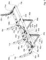
- the Figures 1 to 3 show a first embodiment of an aircraft seat stand device according to the invention.
- the aircraft seat stand device is part of an aircraft seat row 56a which is only partially shown.
- the aircraft seat row 56a comprises three aircraft seats 58a.
- the row of aircraft seats 56a comprises a different number, for example only one, two or four aircraft seats 58a.
- the aircraft seats 58a are provided so that passengers can sit on them during a flight.
- the aircraft seats 58a each have a seat bottom (not shown) and a backrest (not shown).
- each aircraft seat 58a is laterally delimited by an armrest (not shown in more detail).
- Two directly adjacent aircraft seats 58a each have a common armrest.
- the aircraft seats 58a are intended to be erected on a stand level.
- the stand level is formed by a cabin floor of an aircraft.
- the aircraft seats 58a are mounted on the cabin floor in an assembled state by means of the aircraft seat stand device.
- the aircraft seat stand device comprises a first carrier profile 10a.
- the first carrier profile 10a is designed as a front cross tube.
- the aircraft seat stand device further comprises a second carrier profile 12a.
- the second support profile 12a is designed as a rear cross tube.
- the two carrier profiles 10a, 12a are arranged at a distance from one another and run parallel to one another.
- the carrier profile 10a designed as a front cross tube is arranged in a front region of the aircraft seats 58a.
- the second carrier profile 12a which is designed as a rear cross tube, is arranged in a rear region of the aircraft seats 58a.
- the carrier profiles 10a, 12a extend in a transverse direction to the aircraft seats 58a.
- the transverse direction of the aircraft seats 58a is oriented at right angles to a seat direction.
- the two support profiles 10a, 12a designed as cross tubes are essentially identical, which is why only the first support profile 10a, which is designed as a front cross tube, is described in more detail below.
- a description of the first support profile 10a can be used to explain the second support profile 12a, which is designed as a rear cross tube.
- the carrier profile 10a designed as a cross tube is tubular.
- the carrier profile 10a has a cross section, that forms a ring.
- the carrier profile 10a is thin-walled.
- the carrier profile 10a is formed from a fiber composite material. In principle, it is also conceivable that the carrier profile 10a is formed from a light metal, such as an aluminum or magnesium.
- the aircraft seat stand device comprises four first aircraft seat elements 14a, 16a, 18a, 42a.
- the first aircraft seat elements 14a, 16a, 18a, 42a are each designed as a seat divider.
- the first aircraft seat elements 14a, 16a, 18a, 42a designed as seat dividers each delimit a seating area of an aircraft seat 58a.
- two adjacent aircraft seat elements 14a, 16a, 18a, 42a designed as seat dividers delimit an aircraft seat 58a of the aircraft seat row 56a.
- the aircraft seat elements 14a, 16a, 18a, 42a are L-shaped and, in an assembled state, extend from the first support profile 10a designed as a front cross tube to the second support profile 12a designed as a rear cross tube. In the assembled state, the aircraft seat elements 14a, 16a, 18a, 42a designed as seat dividers extend from the first support profile 10a designed as a front cross tube to behind the second support profile 12a designed as a rear cross tube.
- the first aircraft seat elements 14a, 16a, 18a, 42a which are designed as seat dividers, have a kink, from which the aircraft seat elements 14a, 16a, 18a, 42a move upward from the support profiles 10a, 12a , extend away from the insurgent level.
- the first aircraft seat elements 14a, 16a, 18a, 42a which are designed as seat dividers, are each coupled to the carrier profile 12a, which is designed as a rear cross tube.
- the first aircraft seat elements 14a, 16a, 18a, 42a designed as a seat divider, they are each coupled to the support profile 10a designed as a front cross tube.
- the first aircraft seat elements 14a, 16a, 18a, 42a designed as seat dividers each have a receptacle 60a at the front end.
- the receptacle 60a is formed by a through hole.
- the aircraft seat elements 14a, 16a, 18a, 42a, which are designed as seat dividers, are provided so that further components of the aircraft seats 58a or the aircraft seat row 56a, such as in particular armrests and / or backrests, are attached.
- the first aircraft seat elements 14a, 16a, 18a, 42a, which are designed as seat dividers are formed from a light metal, such as in particular an aluminum.
- the outer two first aircraft seat elements designed as seat dividers 18a, 42a configured differently than the inner two first aircraft seat elements 14a, 16a, which are designed as seat dividers.
- the aircraft seat elements 14a, 16a, 18a, 42a are all the same and / or are made of another material, such as a fiber composite material.
- the aircraft seat stand device has a different number of aircraft seat elements 14a, 16a, 18a, 42a designed as seat dividers.
- the aircraft seat stand device comprises four second aircraft seat elements 44a, 46a, 48a, 50a.
- the second aircraft seat elements 44a, 46a, 48a, 50a are each designed as a seat base.
- the second aircraft seat elements 44a, 46a, 48a, 50a, which are designed as seat feet, are intended to stand the aircraft seat stand device and thus the aircraft seat row 56a on the stand level.
- the two second aircraft seat elements 44a, 46a are designed as front seat feet and the other two second aircraft seat elements 48a, 50a as rear seat feet.
- the second aircraft seat elements 44a, 46a, which are designed as front seat feet are coupled in an assembled state to the first carrier profile 10a, which is designed as a front cross tube.
- the second aircraft seat elements 48a, 50a which are designed as rear seat feet, are coupled in an assembled state to the second carrier profile 12a, which is designed as a rear cross tube.
- the second aircraft seat elements 44a, 46a, 48a, 50a are each coupled with an upper end to the respective carrier profile 10a, 12a.
- the second aircraft seat elements 44a, 46a, 48a, 50a each have a receptacle 62a at an upper end.
- the receptacles 62a are each formed by two through holes.
- the second aircraft seat elements 44a, 46a, 48a, 50a which are designed as seat feet, each have connecting elements, which are not shown or described in any more detail, via which the second aircraft seat elements 44a, 46a, 48a, 50a, which are designed as seat feet, are connected to connecting elements introduced into the cabin floor can be.
- the connecting elements of the cabin floor are preferably designed as connecting rails.
- the connecting elements of the second aircraft seat elements 44a, 46a, 48a, 50a, which are designed as seat feet, are designed as fittings which engage positively in the connecting elements, which are designed as connecting rails, for elevating the aircraft seat row 56a.
- the second aircraft seat elements 44a, 46a, 48a, 50a designed as seat feet are different have trained connecting elements that fix the second aircraft seat elements 44a, 46a, 48a, 50a in another way firmly on a stand level.
- the two second aircraft seat elements 44a, 46a, which are designed as front seat feet are designed as essentially straight profiles which, in an assembled state, extend essentially vertically downward from the first carrier profile 10a.
- the two second aircraft seat elements 48a, 50a, which are designed as rear seat feet, are designed as curved profiles which extend both downwards and backwards from the second carrier profile 12a, that is to say away from the first carrier profile 10a.
- one of the second aircraft seat elements 44a, 46a designed as a front seat base is aligned parallel to one of the second aircraft seat elements 48a, 50a designed as a rear seat base.
- the second aircraft seat element 44a, 46a, which is designed as a front seat base, and the second aircraft seat element 48a, 50a, which is designed as a rear seat base, and which are aligned parallel to one another, are each connected to one another at a lower end by means of a connecting rod 64a, 66a.
- the aircraft seat stand device comprises a first intermediate element 20a and a second intermediate element 22a.
- the intermediate elements 20a, 22a completely surround the first carrier profile 10a, which is designed as a front cross tube. In principle, it would also be conceivable that the intermediate elements 20a, 22a only partially surround the first carrier profile 10a in the circumferential direction.
- the intermediate elements 20a, 22a are designed as tubular elements.
- the intermediate elements 20a, 22a, which are designed as tubular elements, are formed from a fiber composite material. In principle, it is also conceivable for the intermediate elements 20a, 22a to be formed from a different material, such as preferably a light metal, such as an aluminum.
- the first intermediate element 20a is coupled to the first aircraft seat element 14a designed as a seat divider.
- first intermediate element 20a is connected to the one second aircraft seat element 44a designed as a front seat foot.
- the first intermediate element 20a is provided for connecting the first aircraft seat element 14a, which is designed as a seat divider, and the second aircraft seat element 44a, which is designed as a front seat base, to the first carrier profile 10a, which is designed as a front cross tube.
- the second intermediate element 22a is provided for connecting the other first aircraft seat element 16a, which is designed as a seat divider, and the other second aircraft seat element 46a, which is designed as a front seat base, to the first carrier profile 10a, which is designed as a front cross tube.
- the first aircraft seat element 16a and the second aircraft seat element 46a are connected to the first carrier profile 10a via the second intermediate element 22a.
- An embodiment of the first intermediate element 20a and the second intermediate element 22a and a connection of the corresponding first aircraft seat element 14a, 16a and the corresponding second aircraft seat element 44a, 46a to the corresponding intermediate element 20a, 22a are identical, which is why in the following only the first intermediate element 20a and the connection of the corresponding first aircraft seat element 14a and the corresponding second aircraft seat element 44a to the intermediate element 20a.
- An embodiment of the second intermediate element 22a and a connection of the corresponding aircraft seat elements 16a, 46a to this intermediate element 22a can be found in the description of the first intermediate element 20a.
- the intermediate element 20a encloses the first carrier profile.
- the intermediate element 20a lies with an inner side on an outer side of the carrier profile 10a.
- the intermediate element 20a is rotatably arranged with respect to the carrier profile 10a.
- the intermediate element 20a can rotate around the carrier profile 10a when a force is applied. As a result, torsional loads on the carrier profile 10a in particular are prevented or minimized in the event of a crash / deformation.
- the intermediate element 20a has a first connection bracket 52a.
- the first connection bracket 52a is formed from a plastic. In principle, it is also conceivable that the first connection bracket 52a is formed from a different material, such as aluminum.
- the connection frame 52a extends in the assembled state in the direction of the first aircraft seat element 14a.
- the connection bracket 52a is integrally connected to the intermediate element 20a.
- the connection block 52a On a first side, the connection block 52a has a connection area over which the connection bracket 52a is connected to the intermediate element 20a.
- connection block 52a is connected to a surface of the intermediate element 20a in the connection area via an adhesive connection.
- the connection area has an extent in the circumferential direction that is less than 180 degrees.
- the connecting block 52a occupies an area of the intermediate element 20a of less than 180 degrees in the circumferential direction.
- connection bracket 52a is formed in one piece with the intermediate element 20a.
- the connection bracket 52a has a receptacle 68a.
- the receptacle 68a is provided for connecting the first aircraft seat element 14a to the connection bracket 52a.
- the receptacle 68a is formed by two spaced apart plates 70a, 72a, each of which has a receiving hole, the receiving holes being aligned with one another.
- the first aircraft seat element 14a is connected to the connection bracket 52a via a fastening element 74a designed as a screw, which is guided through the two receiving holes of the receptacle 68a, and a fastening element designed as a nut, which is connected to the fastening element 74a designed as a screw.
- the first aircraft seat element 14a is aligned with the through hole of its receptacle 60a between the two receptacle holes of the receptacle 68a of the first connection bracket 52a.
- the fastening element 74a which is designed as a screw, is guided through the receiving holes of the receptacle 68a of the first connection bracket 52a and through the through hole of the receptacle 60a of the first aircraft seat element 14a.
- the fastening element 74a designed as a screw is fixed with the fastening element designed as a nut in the receptacle 68a of the first connection bracket 52a and the receptacle 60a of the first aircraft seat element 14a.
- the receptacle 60a of the first connection bracket 52a is configured differently and the first aircraft seat element 14a is connected to the first connection bracket 52a by means of a different fastening method.
- the fastening element 74a for the positive connection of the first aircraft seat element 14a is designed, for example, as a bolt or pin.
- the first aircraft seat element 14a is connected to the connection bracket 52a via a plurality of fastening elements 74a.
- the aircraft seat element 14a is connected to the connection bracket 52a via a differently designed form and / or non-positive connection element.
- the intermediate element 20a has a second connection bracket 54a.
- the second aircraft seat element 44a is coupled to the intermediate element 20a via the second connection bracket 54a.
- the second connection bracket 54a is formed from a plastic. In principle, it is also conceivable that the second connection bracket 54a is also made of a different material, such as aluminum.
- the second connection bracket 54a extends downward in the direction of the second aircraft seat element 44a.
- the second connection bracket 54a is integrally connected to the intermediate element 20a.
- the second connection bracket 54a On a first side, the second connection bracket 54a has a connection area via which the second connection bracket 54a is connected to the intermediate element 20a.
- the second connection bracket 54a is connected to a surface of the intermediate element 20a in the connection area via an adhesive connection.
- the connection area of the second connection block 54a has an extent in the circumferential direction that is less than 180 degrees.
- the second connection bracket 54a is displaced in an axial direction to the first connection bracket 52a. Due to the configuration of the connection areas of the connection blocks 52a, 54a, each of which has an extent in the circumferential direction of less than 180 degrees, it would also be conceivable for the first connection block 52a and the second connection block 54a to be arranged in the same axial position on the intermediate element 20a .
- the two connection brackets 52a, 54a would be arranged one behind the other in the circumferential direction of the intermediate element 20a.
- the second connection bracket 54a has a receptacle 76a.
- the receptacle 76a is provided for connecting the second aircraft seat element 44a to the second connection bracket 54a.
- the receptacle 76a is formed by two spaced-apart plates 78a, 80a, each having two receiving holes, the two receiving holes in one plate 78a, 80a each being aligned with one of the receiving holes in the other plate 78a, 80a.
- the second aircraft seat element 44a is connected with its receptacle 62a to the receptacle 76a of the second connection bracket 54a by means of two fastening elements 82a, 84a and two fastening elements embodied as nuts.
- the second aircraft seat element 44a which is designed as a seat foot, is firmly connected to the intermediate element 20a. It is conceivable that the second connection bracket 54a as the first connection bracket 52a another way of fastening the aircraft seat element 44a can be designed.
- the intermediate element 20a is fixed in an axial direction to the carrier profile 10a on which it is arranged.
- the intermediate element 20a in a normal operating state of the aircraft seat stand device, is arranged in a rotationally fixed manner relative to the carrier profile 10a.
- the intermediate element 20a is secured against rotation up to a defined maximum load.
- the intermediate element 20a is connected to the carrier profile 10a in an assembled and ready-to-operate operating state by means of an adhesive connection.
- An adhesive layer is arranged between an outside of the carrier profile 10a and an inside of the intermediate element 20a, which connects the carrier profile 10a and the intermediate element 20a to one another via an adhesive connection.
- the intermediate element 20a is axially fixed via the adhesive connection in a normal operating state of the aircraft seat stand device.
- the intermediate element 20a is arranged in a rotationally fixed manner on the carrier profile 10a via the adhesive connection. In the normal operating state of the aircraft seat stand device, the intermediate element 20a is fixed firmly on the carrier profile 10a. In principle, it is also conceivable for the intermediate element 20a to be coupled to the carrier profile 10a in another form-fitting and / or non-positive manner for axial and / or rotational securing, for example via a form-locking connection, for example by means of a into the carrier profile 10a and the intermediate element 20a positively engaging pin.
- the intermediate element 20a is arranged on the carrier profile 10a in a rotationally fixed and axially fixed manner in a normal operating state of the aircraft seat stand device.
- the normal operating state is formed from an operating state in which the aircraft seat row 56a, of which the aircraft seat stand device is part, is mounted on an aircraft.
- people can sit on aircraft seats 58a of the aircraft seat row 56a, as a result of which forces are introduced via the seat base and the backrest into the aircraft seat 58a and thus the aircraft seat stand device.
- Forces that are introduced into the first aircraft seat element 14a designed as a seat divider are introduced via the intermediate element 20a into the second aircraft seat element 44a designed as a seat foot.
- a moment resulting from the forces introduced onto the intermediate element 20a and acting on the intermediate element 20a is counteracted by the connection between the intermediate element 20a and the carrier profile 10a Supported profile 10a.
- the adhesive connection between the intermediate element 20a and the shears Support profile 10a and the intermediate element 20a is rotatable to the support profile 10a.
- the intermediate element 20a can rotate to the carrier profile 10a and thus the introduction of a torsional moment from the aircraft seat elements 14a, 44a via the intermediate element 20a into the carrier profile 10a is prevented.
- the carrier profile 10a can be designed to be particularly light and material-saving since it does not have to be designed for torsion loads from the aircraft seat elements 14a, 44a in the event of a crash / deformation.
- the aircraft seat stand device has two further intermediate elements 24a, 26a.
- the two further intermediate elements 24a, 26a are essentially of the same design as the intermediate elements 20a, 22a for connecting the aircraft seat elements 14a, 16a to the first carrier profile 10a.
- the aircraft seat elements 14a, 16a are also connected to the intermediate elements 24a, 26a via connection brackets 98a, 100a, which are not described in any more detail, again with a first aircraft seat element 14a, 16a and a second aircraft seat element 48a, 50a being connected to an intermediate element 24a, 26a.
- the aircraft seat stand device has, for each aircraft seat element 18a, 42a, one intermediate element 28a, 32a for connection to the first carrier profile 10a and one intermediate element 30a, 34a for connection to the second carrier profile 12a.
- the intermediate elements 28a, 30a, 32a, 34a are designed to be equivalent to the other intermediate elements 20a, 22a, 24a, 26a, but each have only one connection bracket, not shown, in order to connect the corresponding aircraft seat element 18a, 42a to the corresponding intermediate element 28a, 30a, 32a, 34a and thereby to tie the corresponding carrier profile 10a, 12a.
- the intermediate elements 28a, 30a, 32a, 34a are equivalent to the other intermediate elements 20a, 22a, 24a, 26a connected to the corresponding carrier profiles 10a, 12a.
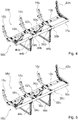
- FIG 4 shows a second embodiment of an aircraft seat stand device according to the invention.
- the aircraft seat stand device is part of an aircraft seat row 56b which is only partially shown.
- the aircraft seat row 56b comprises three aircraft seats 58b.
- the aircraft seat stand device comprises a first carrier profile 10b.
- the first carrier profile 10b is designed as a front cross tube.
- the aircraft seat stand device further comprises a second carrier profile 12b.
- the second support profile 12b is designed as a rear cross tube.
- the carrier profiles 10b, 12b are formed from a light metal.
- the carrier profiles 10b, 12b are formed from an aluminum. In principle, it is also conceivable for the carrier profiles 10b, 12b to be formed from another light material, such as, for example, from a magnesium or titanium.
- the aircraft seat stand device comprises four first aircraft seat elements 14b, 16b, 18b, 42b.
- the first aircraft seat elements 14b, 16b, 18b, 42b are each designed as a seat divider.
- the first aircraft seat elements 14b, 16b, 18b, 42b designed as seat dividers each delimit a seating area of an aircraft seat 58b.
- the first aircraft seat elements 14b, 16b, 18b, 42b designed as seat dividers are essentially of the same design as those of the first exemplary embodiment from FIGS Figures 1 to 3 .
- the aircraft seat stand device comprises four second aircraft seat elements 44b, 46b, 48b, 50b.
- the second aircraft seat elements 44b, 46b, 48b, 50b are each designed as a seat base.
- the second aircraft seat elements 44b, 46b, 48b, 50b designed as seat feet are provided for the aircraft seat support device and thus the aircraft seat row 56b to stand on the level of the insurgent.
- the second aircraft seat elements 44b, 46b, 48b, 50b are configured essentially the same as in the first exemplary embodiment from FIGS Figures 1 to 3 .
- the aircraft seat stand device comprises two first intermediate elements 36b, 38b and two second intermediate elements 40b, 96b.
- the intermediate elements 36b, 38b, 40b, 96b are designed as tubular elements, as in the first exemplary embodiment.
- only one aircraft seat element 14b, 16b, 44b, 46b is coupled to the first and second intermediate elements 36b, 38b, 40b, 96b.
- An embodiment of the two first intermediate elements 36b, 38b and an embodiment of the two second intermediate elements 40b, 96b and a connection of the corresponding first aircraft seat element 14b, 16b or the corresponding second aircraft seat element 44b, 46b to the corresponding intermediate element 36b, 38b, 40b, 96b are identical , which is why only a first intermediate element 36b and a second intermediate element 40b and the connection of the corresponding first aircraft seat element 14b, 16b or the corresponding second aircraft seat element 44b, 46b to the corresponding intermediate element 36b, 38b, 40b, 96b is described below. A description of the corresponding other intermediate element 38b, 96b can be derived from this.
- the first intermediate element 36b is provided for connecting the first aircraft seat element 14b to the carrier profile 10b.
- the first intermediate element 36b has a connection block 52b.
- One connection bracket 52b is designed like the corresponding connection bracket for connecting the first aircraft seat element from the first exemplary embodiment of FIG Figures 1 to 3 .
- the first aircraft seat element 14b is connected to the first intermediate element 36b via a screw connection and is thus coupled to the first carrier profile 10b.
- the first intermediate element 36b like the intermediate elements from the first exemplary embodiment, is connected to the carrier profile by means of an adhesive connection.
- the second intermediate element 40b is provided for connecting the second aircraft seat element 44b to the carrier profile 10b.
- the second intermediate element 40b has a connection bracket 54b.
- One connection bracket 54b is designed like the corresponding connection bracket for connecting the second aircraft seat element from the first exemplary embodiment of FIG Figures 1 to 3 .
- the second aircraft seat element 44b is connected in a fully assembled state via a screw connection to the second intermediate element 40b and thus coupled to the first carrier profile 10b.
- the first intermediate element 40b like the intermediate elements from the first exemplary embodiment, is connected to the carrier profile by means of an adhesive connection.
- the second intermediate element 40b is arranged at a distance from the first intermediate element 36b.
- the first intermediate element 36b and the second intermediate element 40b are independent of one another. It is fundamentally conceivable that the two intermediate elements 36b, 40b are connected to the carrier profile 10b with adhesive connections of different strengths, so that they can be rotated to the carrier profile 10b from loads of different magnitudes.
- FIG. 5 shows a third embodiment of an aircraft seat stand device according to the invention.
- the aircraft seat stand device is part of an aircraft seat row 56c which is only partially shown.
- the aircraft seat row 56c comprises three aircraft seats 58c.
- the aircraft seat stand device comprises a first carrier profile 10c.
- the first carrier profile 10c is designed as a front cross tube.
- the aircraft seat stand device further comprises a second carrier profile 12c.
- the second support profile 12c is designed as a rear cross tube.
- the carrier profiles 10c, 12c are formed from a light metal.
- the aircraft seat stand device comprises four first aircraft seat elements 14c, 16c, 18c, 42c.
- the first aircraft seat elements 14c, 16c, 18c, 42c are each designed as a seat divider.
- the first aircraft seat elements 14c, 16c, 18c, 42c designed as seat dividers each delimit a seating area of an aircraft seat 58c.
- the first aircraft seat elements 14c, 16c, 18c, 42c, which are designed as seat dividers, are essentially of the same design as those of the first exemplary embodiment from FIGS Figures 1 to 3 .
- the aircraft seat stand device comprises four second aircraft seat elements 44c, 46c, 48c, 50c.
- the second aircraft seat elements 44c, 46c, 48c, 50c are each designed as a seat base.
- the second aircraft seat elements 44c, 46c, 48c, 50c which are designed as seat feet, are intended to stand the aircraft seat stand device and thus the aircraft seat row 56c on the stand level.
- the second aircraft seat elements 44c, 46c, 48c, 50c are configured essentially the same as in the first exemplary embodiment from FIGS Figures 1 to 3 .
- the aircraft seat stand device comprises two first intermediate elements 36c, 38c.
- the two first intermediate elements 36c, 38c are equivalent to the two first intermediate elements from the second exemplary embodiment in FIG Figure 4 educated.
- the two first intermediate elements 36c, 38c are provided in each case to connect a first aircraft seat element 14c, 16c designed as a seat divider to the carrier profile 10c.
- a first aircraft seat element 14c, 16c which is designed as a seat divider, is coupled to the corresponding intermediate element 36c, 38c via a connection bracket 52c.
- the second aircraft seat elements 44c, 46c designed as a seat foot are directly coupled to the carrier profile 10c.
- the carrier profile 10c each forms a connection bracket 86c, 88c, via which the second aircraft seat elements 44c, 46c are firmly connected to the carrier profile 10c.
- the second aircraft seat elements 44c, 46c, which are designed as seat bases are connected to the carrier profile 10c in a loop, as is known from the prior art.
- first aircraft seat elements 14c, 16c and the second aircraft seat elements 44c, 46c are carried out in the opposite way to that described above.
- the first aircraft seat elements 14c, 16c which are designed as seat dividers, would be directly and rigidly connected to the carrier profile 10c via a loop or a connection bracket formed by the carrier profile 10c, and the second aircraft seat elements 44c, 46c, which were designed as seat feet, would be connected to the carrier profile 10c via two intermediate elements, and thereby rotatably arranged to the carrier profile 10c in at least one crash / deformation case.
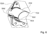
- Figure 6 shows a fourth embodiment of an aircraft seat stand device according to the invention.
- the aircraft seat stand device is part of an only partially shown row of aircraft seats 56d.
- the aircraft seat row 56d comprises three aircraft seats 58d.
- the aircraft seat stand device comprises a first carrier profile 10d.
- the first carrier profile 10d is designed as a front cross tube.
- the aircraft seat stand device further comprises a second carrier profile, which is not shown in detail.
- the carrier profiles are made of a light metal.
- the aircraft seat device Like the other exemplary embodiments, it has first and second aircraft seat elements, which are not shown in more detail here.
- the aircraft seat stand device equivalent to the first exemplary embodiment, comprises a first intermediate element 20d and a second intermediate element, only the first intermediate element 20d being shown and described below.
- the second intermediate element not shown, is equivalent.
- the intermediate element 20d is partially designed differently. Equivalent to the first exemplary embodiment, the intermediate element 20d has a first connection bracket 52d for connecting a first aircraft seat element, which is connected to the intermediate element 20d by means of an adhesive connection.
- the first connection block 52d is of the same design as the corresponding connection block of the first exemplary embodiment.
- the intermediate element 20d has a second connection bracket 54d, which differs from that of the first exemplary embodiment.
- the second connection bracket 54d is connected to the intermediate element 20d via an adhesive connection and a positive connection. In principle, it would also be conceivable that the second connection bracket 54d is only connected to the second intermediate element 20d via a positive connection.
- the intermediate element 20d forms a form-locking element 90d for the positive connection of the connecting block 54d.
- the form-locking element 90d of the intermediate element 20d is designed as an elevation with an undercut 92d.
- the connection bracket 54d forms a form-fitting element 94d which corresponds to the form-fitting element 90d of the intermediate element 20d.
- the form-locking element 94d of the connection bracket 54d is designed as a hook.
- the form-locking element 94d designed as a hook engages in the form-fitting element 90d of the intermediate element 20d in an assembled state.
- This enables a particularly strong and rigid connection between the intermediate element 20d and the second connection bracket 54d to be achieved.
- the second aircraft seat element which is designed as a seat foot, can be connected to the intermediate element 20d in a particularly firm and secure manner and thereby connected to the carrier profile 10d.
- the adhesive connection between the intermediate element 20d and the second connecting block 54d is advantageously reinforced by the positive connection of the positive locking element 94d of the connecting block 54d and the positive locking element 90d of the intermediate element 20d.
Landscapes
- Engineering & Computer Science (AREA)
- Aviation & Aerospace Engineering (AREA)
- Connection Of Plates (AREA)
- Seats For Vehicles (AREA)
- Tires In General (AREA)
Claims (13)
- Dispositif de support de siège d'avion avec au moins un profilé porteur (10a, 12a ; 10b, 12b ; 10c, 12c ; 10d), avec au moins un élément de siège d'avion (14a, 16a, 18a, 42a, 44a, 46a, 48a, 50a ; 14b, 16b, 18b, 42b ; 14c, 16c, 18c, 42c), qui est réalisé comme partageur de sièges ou comme piètement de siège, et avec au moins un élément intermédiaire (20a, 22a, 24a, 26a, 28a, 30a, 32a, 34a ; 36b, 38b, 40b, 96b ; 36c, 40c ; 20d) qui au moins sensiblement entoure l'au moins un profilé porteur (10a, 12a ; 10b, 12b ; 10c, 12c ; 10d) et est couplé avec l'au moins un élément de siège d'avion (14a, 16a, 18a, 42a, 44a, 46a, 48a, 50a ; 14b, 16b, 18b, 42b ; 14c, 16c, 18c, 42c), l'élément intermédiaire étant fixé en direction axiale par rapport au profilé porteur sur lequel il est disposé,
où en état d'opération normal l'élément intermédiaire (20a, 22a, 24a, 26a, 28a, 30a, 32a, 34a ; 36b, 38b, 40b, 96b ; 36c, 40c ; 20d) est disposé solidaire en rotation avec le profilé porteur (10a, 12a ; 10b, 12b ; 10c, 12c ; 10d),
où l'élément intermédiaire (20a, 22a, 24a, 26a, 28a, 30a, 32a, 34a ; 36b, 38b, 40b, 96b ; 36c, 40c ; 20d) est sécurisé contre une rotation jusqu'à une charge maximale définie,
où au moins en cas d'un crash/d'une déformation l'élément intermédiaire (20a, 22a, 24a, 26a, 28a, 30a, 32a, 34a ; 36b, 38b, 40b, 96b ; 36c, 40c ; 20d) est disposé de manière rotative par rapport au profilé porteur (10a, 12a ; 10b, 12b ; 10c, 12c ; 10d),
des contraintes de torsion sur le profilé porteur (10a, 12a ; 10b, 12b ; 10c, 12c ; 10d) étant donc empêchées ou minimisées. - Dispositif de support de siège d'avion selon la revendication 1,
caractérisé en ce qu'en état d'opération normal l'élément intermédiaire (20a, 22a, 24a, 26a, 28a, 30a, 32a, 34a ; 36b, 38b, 40b, 96b ; 36c, 40c ; 20d) est disposé sur le profilé porteur (10a, 12a ; 10b, 12b ; 10c, 12c ; 10d) solidairement en rotation et par fixation adhésive axiale. - Dispositif de support de siège d'avion selon la revendication 1 ou 2,
caractérisé par au moins un élément de siège d'avion de plus (44a, 46a, 48a, 50a), qui est couplé avec l'élément intermédiaire (20a, 22a, 24a, 26a). - Dispositif de support de siège d'avion selon l'une quelconque des revendications précédentes,
caractérisé en ce que l'élément intermédiaire (20a, 22a, 24a, 26a, 28a, 30a, 32a, 34a ; 36b, 38b ; 36c, 40c) comporte au moins un tréteau de raccordement (52a, 54a ; 52b, 54b ; 52c ; 52d, 54d), par le biais duquel l'élément de siège d'avion (14a, 16a, 18a, 42a, 44a, 46a, 48a, 50a ; 14b, 16b, 18b, 42b ; 14c, 16c, 18c, 42c) est couplé avec l'élément intermédiaire (20a, 22a, 24a, 26a, 28a, 30a, 32a, 34a ; 36b, 38b ; 36c, 40c) par accouplement de matière. - Dispositif de support de siège d'avion selon la revendication 4,
caractérisé en ce que le tréteau de raccordement (52a, 54a ; 52b, 54b ; 52c ; 52d, 54d) est couplé avec l'élément intermédiaire (20a, 22a, 24a, 26a, 28a, 30a, 32a, 34a ; 36b, 38b ; 36c, 40c). - Dispositif de support de siège d'avion selon la revendication 4 ou 5,
caractérisé en ce que le tréteau de raccordement (52a, 54a ; 52b, 54b ; 52c ; 52d, 54d) comporte dans une zone du raccordement avec l'élément intermédiaire (20a, 22a, 24a, 26a, 28a, 30a, 32a, 34a ; 36b, 38b ; 36c, 40c) une extension en direction circonférentielle qui est moins de 180 degrés. - Dispositif de support de siège d'avion selon l'une quelconque des revendications précédentes,
caractérisé en ce que l'au moins un élément intermédiaire (20a, 22a, 24a, 26a, 28a, 30a, 32a, 34a ; 36b, 38b ; 36c, 40c) est fixé par rapport au profilé porteur (10a, 12a ; 10b, 12b ; 10c, 12c ; 10d) en au moins une direction axiale. - Dispositif de support de siège d'avion selon l'une quelconque des revendications précédentes,
caractérisé en ce qu'en au moins un état d'opération l'élément intermédiaire (20a, 22a, 24a, 26a, 28a, 30a, 32a, 34a ; 36b, 38b ; 36c, 40c) est agencé solidaire en rotation avec le profilé porteur (10a, 12a ; 10b, 12b ; 10c, 12c ; 10d). - Dispositif de support de siège d'avion selon l'une quelconque des revendications précédentes,
caractérisé en ce qu'en au moins un état d'opération l'élément intermédiaire (20a, 22a, 24a, 26a, 28a, 30a, 32a, 34a ; 36b, 38b ; 36c, 40c) est connecté fixement avec le profilé porteur (10a, 12a ; 10b, 12b ; 10c, 12c ; 10d) par une connexion adhésive. - Dispositif de support de siège d'avion selon l'une quelconque des revendications précédentes,
caractérisé en ce que le profilé porteur (10a, 12a ; 10b, 12b ; 10c, 12c ; 10d) est formé au moins sensiblement d'un métal léger et/ou d'un matériau plastique renforcé de fibres. - Dispositif de support de siège d'avion au moins selon la revendication 1,
caractérisé par au moins un deuxième élément intermédiaire (40b, 96b),
où respectivement seulement un élément de siège d'avion (14b, 16b, 18b, 42b, 44b, 46b, 48b, 50b) est couplé avec l'un des deux éléments intermédiaires (36b, 38b, 40b, 96b). - Dispositif de support de siège d'avion au moins selon la revendication 1,
caractérisé par au moins un élément de siège d'avion de plus (44c, 46c), qui est couplé avec le profilé porteur (10c) directement. - Siège d'avion avec un dispositif de siège d'avion selon l'une quelconque des revendications précédentes.
Applications Claiming Priority (2)
| Application Number | Priority Date | Filing Date | Title |
|---|---|---|---|
| DE102013114130.7A DE102013114130A1 (de) | 2013-12-16 | 2013-12-16 | Flugzeugsitzaufständervorrichtung |
| PCT/EP2014/077995 WO2015091507A1 (fr) | 2013-12-16 | 2014-12-16 | Dispositif de support de siège d'avion |
Publications (2)
| Publication Number | Publication Date |
|---|---|
| EP3083401A1 EP3083401A1 (fr) | 2016-10-26 |
| EP3083401B1 true EP3083401B1 (fr) | 2020-06-24 |
Family
ID=52117893
Family Applications (1)
| Application Number | Title | Priority Date | Filing Date |
|---|---|---|---|
| EP14814838.0A Active EP3083401B1 (fr) | 2013-12-16 | 2014-12-16 | Dispositif de support de siège d'avion |
Country Status (5)
| Country | Link |
|---|---|
| US (1) | US10414504B2 (fr) |
| EP (1) | EP3083401B1 (fr) |
| CN (1) | CN106029497B (fr) |
| DE (1) | DE102013114130A1 (fr) |
| WO (1) | WO2015091507A1 (fr) |
Families Citing this family (5)
| Publication number | Priority date | Publication date | Assignee | Title |
|---|---|---|---|---|
| US10124899B2 (en) * | 2014-06-03 | 2018-11-13 | Zodiac Seats Us Llc | Hybrid composite structural member |
| WO2018089056A1 (fr) * | 2016-11-10 | 2018-05-17 | Zodiac Seats Us Llc | Tubes de châssis présentant des sections transversales non circulaires |
| DE102018119846A1 (de) * | 2018-08-15 | 2020-02-20 | Recaro Aircraft Seating Gmbh & Co. Kg | Flugzeugsitzbefestigungsvorrichtung |
| US11260774B2 (en) | 2020-04-13 | 2022-03-01 | Freedman Seating Company | Modular transportation seat frame |
| US11608177B2 (en) * | 2020-12-21 | 2023-03-21 | B/E Aerospace, Inc. | Aircraft passenger seat row with cabin attendant seat |
Citations (1)
| Publication number | Priority date | Publication date | Assignee | Title |
|---|---|---|---|---|
| EP0423348A1 (fr) * | 1989-02-23 | 1991-04-24 | Koito Industries, Ltd. | Structure de jambe de siege permettant d'absorber l'energie d'impact |
Family Cites Families (11)
| Publication number | Priority date | Publication date | Assignee | Title |
|---|---|---|---|---|
| FR2148929A5 (fr) | 1971-08-10 | 1973-03-23 | Sicma | |
| US4911381A (en) * | 1987-12-28 | 1990-03-27 | Simula, Inc. | Energy-absorbing leg assembly for aircraft passenger seats |
| US5553923A (en) * | 1993-12-08 | 1996-09-10 | Weber Aircraft, Inc. | Base frame for an aircraft seat |
| US5522640A (en) * | 1994-12-02 | 1996-06-04 | Weber Aircraft, Inc. | Apparatus for an energy dissipating seat leg |
| US5657950A (en) * | 1995-08-14 | 1997-08-19 | Industrial Technology Research Intitute | Backward-leaning-movement seat leg structure |
| US5730492A (en) * | 1996-02-09 | 1998-03-24 | Simula Inc. | Load-limiting seat |
| US7716797B2 (en) * | 2006-12-22 | 2010-05-18 | The Boeing Company | Composite seat pan structure for a lightweight aircraft seat assembly |
| CN101492095A (zh) * | 2008-12-17 | 2009-07-29 | 航宇救生装备有限公司 | 整体吸能航空座椅 |
| DE102009014721A1 (de) | 2009-03-27 | 2010-10-07 | Recaro Aircraft Seating Gmbh & Co. Kg | Sitzgestellvorrichtung |
| DE102009014720A1 (de) * | 2009-03-27 | 2010-09-30 | Recaro Aircraft Seating Gmbh & Co. Kg | Sitzgestellvorrichtung |
| DE102012020032B4 (de) * | 2012-10-12 | 2022-12-29 | Recaro Aircraft Seating Gmbh & Co. Kg | Sitzaufständervorrichtung, Sitz und Verfahren zur Montage der Sitzaufständervorrichtung |
-
2013
- 2013-12-16 DE DE102013114130.7A patent/DE102013114130A1/de not_active Withdrawn
-
2014
- 2014-12-16 EP EP14814838.0A patent/EP3083401B1/fr active Active
- 2014-12-16 CN CN201480075645.XA patent/CN106029497B/zh active Active
- 2014-12-16 WO PCT/EP2014/077995 patent/WO2015091507A1/fr not_active Ceased
- 2014-12-16 US US15/104,678 patent/US10414504B2/en active Active
Patent Citations (1)
| Publication number | Priority date | Publication date | Assignee | Title |
|---|---|---|---|---|
| EP0423348A1 (fr) * | 1989-02-23 | 1991-04-24 | Koito Industries, Ltd. | Structure de jambe de siege permettant d'absorber l'energie d'impact |
Also Published As
| Publication number | Publication date |
|---|---|
| EP3083401A1 (fr) | 2016-10-26 |
| DE102013114130A1 (de) | 2015-06-18 |
| CN106029497B (zh) | 2018-07-20 |
| WO2015091507A1 (fr) | 2015-06-25 |
| CN106029497A (zh) | 2016-10-12 |
| US10414504B2 (en) | 2019-09-17 |
| US20160340045A1 (en) | 2016-11-24 |
Similar Documents
| Publication | Publication Date | Title |
|---|---|---|
| EP2706010B1 (fr) | Dispositif d'absorption de l'énergie d'assise | |
| EP3083401B1 (fr) | Dispositif de support de siège d'avion | |
| EP3416888B1 (fr) | Dispositif formant siège d'avion | |
| DE102013003787B4 (de) | Fahrzeugsitz | |
| EP3274213B1 (fr) | Ensemble adaptateur pour siège de véhicule et siège de véhicule | |
| EP4144597A1 (fr) | Structure de siège de véhicule et procédé de montage d'une structure de siège de véhicule | |
| EP4041632B1 (fr) | Siège de passager d'un avion comprenant un cadre et une rangée de sièges | |
| EP2703289B1 (fr) | Dispositif séparateur de siège | |
| DE102012020032A1 (de) | Sitzaufständervorrichtung | |
| DE102004025982B4 (de) | Zweiholmerchassis für Fluggastsitz | |
| EP4321378A2 (fr) | Cadre pour un siège de véhicule et siège de véhicule équipé dudit cadre | |
| DE202008002339U1 (de) | Fahrzeugsitz, insbesondere Nutzfahrzeugsitz | |
| DE102007024341B3 (de) | Fahrzeugsitz, insbesondere Kraftfahrzeugsitz | |
| DE69604620T2 (de) | Gelenkverbindung zwischen der Rückenlehne und dem Sitzteil eines Fahrzeugsitzes | |
| DE102016111983A1 (de) | Modulares Schienensystem | |
| DE102010042881B4 (de) | Fahrzeugsitz mit einer Sitztiefenverstelleinrichtung | |
| DE102009005759B4 (de) | Tunnelstrebe für eine Karosserie eines Personenkraftwagens sowie Karosserie eines Personenkraftwagens | |
| EP3129285B1 (fr) | Système de bâti de siège d'avion | |
| DE19523014A1 (de) | Profil zur Befestigung von Fahrgastsitzen | |
| EP2714462B1 (fr) | Siège de véhicule, en particulier siège de véhicule automobile | |
| EP1600376B1 (fr) | Châssis à deux montants pour siège de passager d'aéronef | |
| DE102024107265A1 (de) | Befestigungsstruktur zur Befestigung eines Fahrzeugsitzes | |
| DE10053048B4 (de) | Fahrzeugsitz | |
| DE10054429A1 (de) | Fahrzeugsitz | |
| DE102017223537A1 (de) | Sitzeinheit für ein fahrzeug, insbesondere ein luftfahrzeug |
Legal Events
| Date | Code | Title | Description |
|---|---|---|---|
| PUAI | Public reference made under article 153(3) epc to a published international application that has entered the european phase |
Free format text: ORIGINAL CODE: 0009012 |
|
| 17P | Request for examination filed |
Effective date: 20160711 |
|
| AK | Designated contracting states |
Kind code of ref document: A1 Designated state(s): AL AT BE BG CH CY CZ DE DK EE ES FI FR GB GR HR HU IE IS IT LI LT LU LV MC MK MT NL NO PL PT RO RS SE SI SK SM TR |
|
| AX | Request for extension of the european patent |
Extension state: BA ME |
|
| DAX | Request for extension of the european patent (deleted) | ||
| STAA | Information on the status of an ep patent application or granted ep patent |
Free format text: STATUS: EXAMINATION IS IN PROGRESS |
|
| 17Q | First examination report despatched |
Effective date: 20190710 |
|
| GRAP | Despatch of communication of intention to grant a patent |
Free format text: ORIGINAL CODE: EPIDOSNIGR1 |
|
| STAA | Information on the status of an ep patent application or granted ep patent |
Free format text: STATUS: GRANT OF PATENT IS INTENDED |
|
| INTG | Intention to grant announced |
Effective date: 20200103 |
|
| GRAS | Grant fee paid |
Free format text: ORIGINAL CODE: EPIDOSNIGR3 |
|
| GRAA | (expected) grant |
Free format text: ORIGINAL CODE: 0009210 |
|
| STAA | Information on the status of an ep patent application or granted ep patent |
Free format text: STATUS: THE PATENT HAS BEEN GRANTED |
|
| AK | Designated contracting states |
Kind code of ref document: B1 Designated state(s): AL AT BE BG CH CY CZ DE DK EE ES FI FR GB GR HR HU IE IS IT LI LT LU LV MC MK MT NL NO PL PT RO RS SE SI SK SM TR |
|
| REG | Reference to a national code |
Ref country code: GB Ref legal event code: FG4D Free format text: NOT ENGLISH |
|
| REG | Reference to a national code |
Ref country code: CH Ref legal event code: EP |
|
| REG | Reference to a national code |
Ref country code: AT Ref legal event code: REF Ref document number: 1283655 Country of ref document: AT Kind code of ref document: T Effective date: 20200715 |
|
| REG | Reference to a national code |
Ref country code: DE Ref legal event code: R096 Ref document number: 502014014373 Country of ref document: DE |
|
| REG | Reference to a national code |
Ref country code: IE Ref legal event code: FG4D Free format text: LANGUAGE OF EP DOCUMENT: GERMAN |
|
| PG25 | Lapsed in a contracting state [announced via postgrant information from national office to epo] |
Ref country code: GR Free format text: LAPSE BECAUSE OF FAILURE TO SUBMIT A TRANSLATION OF THE DESCRIPTION OR TO PAY THE FEE WITHIN THE PRESCRIBED TIME-LIMIT Effective date: 20200925 Ref country code: SE Free format text: LAPSE BECAUSE OF FAILURE TO SUBMIT A TRANSLATION OF THE DESCRIPTION OR TO PAY THE FEE WITHIN THE PRESCRIBED TIME-LIMIT Effective date: 20200624 Ref country code: FI Free format text: LAPSE BECAUSE OF FAILURE TO SUBMIT A TRANSLATION OF THE DESCRIPTION OR TO PAY THE FEE WITHIN THE PRESCRIBED TIME-LIMIT Effective date: 20200624 Ref country code: NO Free format text: LAPSE BECAUSE OF FAILURE TO SUBMIT A TRANSLATION OF THE DESCRIPTION OR TO PAY THE FEE WITHIN THE PRESCRIBED TIME-LIMIT Effective date: 20200924 Ref country code: LT Free format text: LAPSE BECAUSE OF FAILURE TO SUBMIT A TRANSLATION OF THE DESCRIPTION OR TO PAY THE FEE WITHIN THE PRESCRIBED TIME-LIMIT Effective date: 20200624 |
|
| REG | Reference to a national code |
Ref country code: LT Ref legal event code: MG4D |
|
| PG25 | Lapsed in a contracting state [announced via postgrant information from national office to epo] |
Ref country code: BG Free format text: LAPSE BECAUSE OF FAILURE TO SUBMIT A TRANSLATION OF THE DESCRIPTION OR TO PAY THE FEE WITHIN THE PRESCRIBED TIME-LIMIT Effective date: 20200924 Ref country code: LV Free format text: LAPSE BECAUSE OF FAILURE TO SUBMIT A TRANSLATION OF THE DESCRIPTION OR TO PAY THE FEE WITHIN THE PRESCRIBED TIME-LIMIT Effective date: 20200624 Ref country code: RS Free format text: LAPSE BECAUSE OF FAILURE TO SUBMIT A TRANSLATION OF THE DESCRIPTION OR TO PAY THE FEE WITHIN THE PRESCRIBED TIME-LIMIT Effective date: 20200624 Ref country code: HR Free format text: LAPSE BECAUSE OF FAILURE TO SUBMIT A TRANSLATION OF THE DESCRIPTION OR TO PAY THE FEE WITHIN THE PRESCRIBED TIME-LIMIT Effective date: 20200624 |
|
| REG | Reference to a national code |
Ref country code: NL Ref legal event code: MP Effective date: 20200624 |
|
| PG25 | Lapsed in a contracting state [announced via postgrant information from national office to epo] |
Ref country code: NL Free format text: LAPSE BECAUSE OF FAILURE TO SUBMIT A TRANSLATION OF THE DESCRIPTION OR TO PAY THE FEE WITHIN THE PRESCRIBED TIME-LIMIT Effective date: 20200624 Ref country code: AL Free format text: LAPSE BECAUSE OF FAILURE TO SUBMIT A TRANSLATION OF THE DESCRIPTION OR TO PAY THE FEE WITHIN THE PRESCRIBED TIME-LIMIT Effective date: 20200624 |
|
| PG25 | Lapsed in a contracting state [announced via postgrant information from national office to epo] |
Ref country code: EE Free format text: LAPSE BECAUSE OF FAILURE TO SUBMIT A TRANSLATION OF THE DESCRIPTION OR TO PAY THE FEE WITHIN THE PRESCRIBED TIME-LIMIT Effective date: 20200624 Ref country code: IT Free format text: LAPSE BECAUSE OF FAILURE TO SUBMIT A TRANSLATION OF THE DESCRIPTION OR TO PAY THE FEE WITHIN THE PRESCRIBED TIME-LIMIT Effective date: 20200624 Ref country code: RO Free format text: LAPSE BECAUSE OF FAILURE TO SUBMIT A TRANSLATION OF THE DESCRIPTION OR TO PAY THE FEE WITHIN THE PRESCRIBED TIME-LIMIT Effective date: 20200624 Ref country code: SM Free format text: LAPSE BECAUSE OF FAILURE TO SUBMIT A TRANSLATION OF THE DESCRIPTION OR TO PAY THE FEE WITHIN THE PRESCRIBED TIME-LIMIT Effective date: 20200624 Ref country code: PT Free format text: LAPSE BECAUSE OF FAILURE TO SUBMIT A TRANSLATION OF THE DESCRIPTION OR TO PAY THE FEE WITHIN THE PRESCRIBED TIME-LIMIT Effective date: 20201026 Ref country code: CZ Free format text: LAPSE BECAUSE OF FAILURE TO SUBMIT A TRANSLATION OF THE DESCRIPTION OR TO PAY THE FEE WITHIN THE PRESCRIBED TIME-LIMIT Effective date: 20200624 Ref country code: ES Free format text: LAPSE BECAUSE OF FAILURE TO SUBMIT A TRANSLATION OF THE DESCRIPTION OR TO PAY THE FEE WITHIN THE PRESCRIBED TIME-LIMIT Effective date: 20200624 |
|
| PG25 | Lapsed in a contracting state [announced via postgrant information from national office to epo] |
Ref country code: IS Free format text: LAPSE BECAUSE OF FAILURE TO SUBMIT A TRANSLATION OF THE DESCRIPTION OR TO PAY THE FEE WITHIN THE PRESCRIBED TIME-LIMIT Effective date: 20201024 Ref country code: SK Free format text: LAPSE BECAUSE OF FAILURE TO SUBMIT A TRANSLATION OF THE DESCRIPTION OR TO PAY THE FEE WITHIN THE PRESCRIBED TIME-LIMIT Effective date: 20200624 Ref country code: PL Free format text: LAPSE BECAUSE OF FAILURE TO SUBMIT A TRANSLATION OF THE DESCRIPTION OR TO PAY THE FEE WITHIN THE PRESCRIBED TIME-LIMIT Effective date: 20200624 |
|
| REG | Reference to a national code |
Ref country code: DE Ref legal event code: R097 Ref document number: 502014014373 Country of ref document: DE |
|
| PG25 | Lapsed in a contracting state [announced via postgrant information from national office to epo] |
Ref country code: DK Free format text: LAPSE BECAUSE OF FAILURE TO SUBMIT A TRANSLATION OF THE DESCRIPTION OR TO PAY THE FEE WITHIN THE PRESCRIBED TIME-LIMIT Effective date: 20200624 |
|
| PLBE | No opposition filed within time limit |
Free format text: ORIGINAL CODE: 0009261 |
|
| STAA | Information on the status of an ep patent application or granted ep patent |
Free format text: STATUS: NO OPPOSITION FILED WITHIN TIME LIMIT |
|
| 26N | No opposition filed |
Effective date: 20210325 |
|
| REG | Reference to a national code |
Ref country code: CH Ref legal event code: PL |
|
| PG25 | Lapsed in a contracting state [announced via postgrant information from national office to epo] |
Ref country code: SI Free format text: LAPSE BECAUSE OF FAILURE TO SUBMIT A TRANSLATION OF THE DESCRIPTION OR TO PAY THE FEE WITHIN THE PRESCRIBED TIME-LIMIT Effective date: 20200624 Ref country code: MC Free format text: LAPSE BECAUSE OF FAILURE TO SUBMIT A TRANSLATION OF THE DESCRIPTION OR TO PAY THE FEE WITHIN THE PRESCRIBED TIME-LIMIT Effective date: 20200624 |
|
| REG | Reference to a national code |
Ref country code: BE Ref legal event code: MM Effective date: 20201231 |
|
| PG25 | Lapsed in a contracting state [announced via postgrant information from national office to epo] |
Ref country code: LU Free format text: LAPSE BECAUSE OF NON-PAYMENT OF DUE FEES Effective date: 20201216 Ref country code: IE Free format text: LAPSE BECAUSE OF NON-PAYMENT OF DUE FEES Effective date: 20201216 |
|
| PG25 | Lapsed in a contracting state [announced via postgrant information from national office to epo] |
Ref country code: LI Free format text: LAPSE BECAUSE OF NON-PAYMENT OF DUE FEES Effective date: 20201231 Ref country code: CH Free format text: LAPSE BECAUSE OF NON-PAYMENT OF DUE FEES Effective date: 20201231 |
|
| REG | Reference to a national code |
Ref country code: AT Ref legal event code: MM01 Ref document number: 1283655 Country of ref document: AT Kind code of ref document: T Effective date: 20201216 |
|
| PG25 | Lapsed in a contracting state [announced via postgrant information from national office to epo] |
Ref country code: AT Free format text: LAPSE BECAUSE OF NON-PAYMENT OF DUE FEES Effective date: 20201216 |
|
| PG25 | Lapsed in a contracting state [announced via postgrant information from national office to epo] |
Ref country code: TR Free format text: LAPSE BECAUSE OF FAILURE TO SUBMIT A TRANSLATION OF THE DESCRIPTION OR TO PAY THE FEE WITHIN THE PRESCRIBED TIME-LIMIT Effective date: 20200624 Ref country code: MT Free format text: LAPSE BECAUSE OF FAILURE TO SUBMIT A TRANSLATION OF THE DESCRIPTION OR TO PAY THE FEE WITHIN THE PRESCRIBED TIME-LIMIT Effective date: 20200624 Ref country code: CY Free format text: LAPSE BECAUSE OF FAILURE TO SUBMIT A TRANSLATION OF THE DESCRIPTION OR TO PAY THE FEE WITHIN THE PRESCRIBED TIME-LIMIT Effective date: 20200624 |
|
| PG25 | Lapsed in a contracting state [announced via postgrant information from national office to epo] |
Ref country code: MK Free format text: LAPSE BECAUSE OF FAILURE TO SUBMIT A TRANSLATION OF THE DESCRIPTION OR TO PAY THE FEE WITHIN THE PRESCRIBED TIME-LIMIT Effective date: 20200624 |
|
| PG25 | Lapsed in a contracting state [announced via postgrant information from national office to epo] |
Ref country code: BE Free format text: LAPSE BECAUSE OF NON-PAYMENT OF DUE FEES Effective date: 20201231 |
|
| P01 | Opt-out of the competence of the unified patent court (upc) registered |
Effective date: 20230908 |
|
| PGFP | Annual fee paid to national office [announced via postgrant information from national office to epo] |
Ref country code: GB Payment date: 20241218 Year of fee payment: 11 |
|
| PGFP | Annual fee paid to national office [announced via postgrant information from national office to epo] |
Ref country code: FR Payment date: 20251219 Year of fee payment: 12 |
|
| PGFP | Annual fee paid to national office [announced via postgrant information from national office to epo] |
Ref country code: DE Payment date: 20251222 Year of fee payment: 12 |