EP3083440B1 - Conteneur - Google Patents
Conteneur Download PDFInfo
- Publication number
- EP3083440B1 EP3083440B1 EP14835687.6A EP14835687A EP3083440B1 EP 3083440 B1 EP3083440 B1 EP 3083440B1 EP 14835687 A EP14835687 A EP 14835687A EP 3083440 B1 EP3083440 B1 EP 3083440B1
- Authority
- EP
- European Patent Office
- Prior art keywords
- container
- closure
- container according
- plane
- opening
- Prior art date
- Legal status (The legal status is an assumption and is not a legal conclusion. Google has not performed a legal analysis and makes no representation as to the accuracy of the status listed.)
- Active
Links
Images









Classifications
-
- A—HUMAN NECESSITIES
- A47—FURNITURE; DOMESTIC ARTICLES OR APPLIANCES; COFFEE MILLS; SPICE MILLS; SUCTION CLEANERS IN GENERAL
- A47K—SANITARY EQUIPMENT; ACCESSORIES THEREFOR, e.g. TOILET ACCESSORIES
- A47K5/00—Holders or dispensers for soap, toothpaste or the like
- A47K5/06—Dispensers for soap
- A47K5/12—Dispensers for soap for liquid or pasty soap
- A47K5/13—Dispensers for soap for liquid or pasty soap of invertible type
-
- A—HUMAN NECESSITIES
- A47—FURNITURE; DOMESTIC ARTICLES OR APPLIANCES; COFFEE MILLS; SPICE MILLS; SUCTION CLEANERS IN GENERAL
- A47K—SANITARY EQUIPMENT; ACCESSORIES THEREFOR, e.g. TOILET ACCESSORIES
- A47K5/00—Holders or dispensers for soap, toothpaste or the like
- A47K5/06—Dispensers for soap
- A47K5/12—Dispensers for soap for liquid or pasty soap
-
- B—PERFORMING OPERATIONS; TRANSPORTING
- B65—CONVEYING; PACKING; STORING; HANDLING THIN OR FILAMENTARY MATERIAL
- B65D—CONTAINERS FOR STORAGE OR TRANSPORT OF ARTICLES OR MATERIALS, e.g. BAGS, BARRELS, BOTTLES, BOXES, CANS, CARTONS, CRATES, DRUMS, JARS, TANKS, HOPPERS, FORWARDING CONTAINERS; ACCESSORIES, CLOSURES, OR FITTINGS THEREFOR; PACKAGING ELEMENTS; PACKAGES
- B65D41/00—Caps, e.g. crown caps or crown seals, i.e. members having parts arranged for engagement with the external periphery of a neck or wall defining a pouring opening or discharge aperture; Protective cap-like covers for closure members, e.g. decorative covers of metal foil or paper
- B65D41/02—Caps or cap-like covers without lines of weakness, tearing strips, tags, or like opening or removal devices
- B65D41/026—Caps or cap-like covers attached to the bottle neck by sliding them perpendicularly to the neck axis
-
- B—PERFORMING OPERATIONS; TRANSPORTING
- B65—CONVEYING; PACKING; STORING; HANDLING THIN OR FILAMENTARY MATERIAL
- B65D—CONTAINERS FOR STORAGE OR TRANSPORT OF ARTICLES OR MATERIALS, e.g. BAGS, BARRELS, BOTTLES, BOXES, CANS, CARTONS, CRATES, DRUMS, JARS, TANKS, HOPPERS, FORWARDING CONTAINERS; ACCESSORIES, CLOSURES, OR FITTINGS THEREFOR; PACKAGING ELEMENTS; PACKAGES
- B65D43/00—Lids or covers for rigid or semi-rigid containers
- B65D43/02—Removable lids or covers
- B65D43/12—Removable lids or covers guided for removal by sliding
-
- B—PERFORMING OPERATIONS; TRANSPORTING
- B65—CONVEYING; PACKING; STORING; HANDLING THIN OR FILAMENTARY MATERIAL
- B65D—CONTAINERS FOR STORAGE OR TRANSPORT OF ARTICLES OR MATERIALS, e.g. BAGS, BARRELS, BOTTLES, BOXES, CANS, CARTONS, CRATES, DRUMS, JARS, TANKS, HOPPERS, FORWARDING CONTAINERS; ACCESSORIES, CLOSURES, OR FITTINGS THEREFOR; PACKAGING ELEMENTS; PACKAGES
- B65D47/00—Closures with filling and discharging, or with discharging, devices
- B65D47/04—Closures with discharging devices other than pumps
- B65D47/06—Closures with discharging devices other than pumps with pouring spouts or tubes; with discharge nozzles or passages
- B65D47/12—Closures with discharging devices other than pumps with pouring spouts or tubes; with discharge nozzles or passages having removable closures
-
- B—PERFORMING OPERATIONS; TRANSPORTING
- B65—CONVEYING; PACKING; STORING; HANDLING THIN OR FILAMENTARY MATERIAL
- B65D—CONTAINERS FOR STORAGE OR TRANSPORT OF ARTICLES OR MATERIALS, e.g. BAGS, BARRELS, BOTTLES, BOXES, CANS, CARTONS, CRATES, DRUMS, JARS, TANKS, HOPPERS, FORWARDING CONTAINERS; ACCESSORIES, CLOSURES, OR FITTINGS THEREFOR; PACKAGING ELEMENTS; PACKAGES
- B65D47/00—Closures with filling and discharging, or with discharging, devices
- B65D47/04—Closures with discharging devices other than pumps
- B65D47/20—Closures with discharging devices other than pumps comprising hand-operated members for controlling discharge
- B65D47/26—Closures with discharging devices other than pumps comprising hand-operated members for controlling discharge with slide valves, i.e. valves that open and close a passageway by sliding over a port, e.g. formed with slidable spouts
- B65D47/28—Closures with discharging devices other than pumps comprising hand-operated members for controlling discharge with slide valves, i.e. valves that open and close a passageway by sliding over a port, e.g. formed with slidable spouts having linear movement
- B65D47/286—Closures with discharging devices other than pumps comprising hand-operated members for controlling discharge with slide valves, i.e. valves that open and close a passageway by sliding over a port, e.g. formed with slidable spouts having linear movement between planar parts
-
- B—PERFORMING OPERATIONS; TRANSPORTING
- B65—CONVEYING; PACKING; STORING; HANDLING THIN OR FILAMENTARY MATERIAL
- B65D—CONTAINERS FOR STORAGE OR TRANSPORT OF ARTICLES OR MATERIALS, e.g. BAGS, BARRELS, BOTTLES, BOXES, CANS, CARTONS, CRATES, DRUMS, JARS, TANKS, HOPPERS, FORWARDING CONTAINERS; ACCESSORIES, CLOSURES, OR FITTINGS THEREFOR; PACKAGING ELEMENTS; PACKAGES
- B65D75/00—Packages comprising articles or materials partially or wholly enclosed in strips, sheets, blanks, tubes or webs of flexible sheet material, e.g. in folded wrappers
- B65D75/40—Packages formed by enclosing successive articles, or increments of material, in webs, e.g. folded or tubular webs, or by subdividing tubes filled with liquid, semi-liquid, or plastic materials
- B65D75/44—Individual packages cut from webs or tubes
- B65D75/48—Individual packages cut from webs or tubes containing liquids, semiliquids, or pastes, e.g. cushion-shaped packages
-
- B—PERFORMING OPERATIONS; TRANSPORTING
- B65—CONVEYING; PACKING; STORING; HANDLING THIN OR FILAMENTARY MATERIAL
- B65D—CONTAINERS FOR STORAGE OR TRANSPORT OF ARTICLES OR MATERIALS, e.g. BAGS, BARRELS, BOTTLES, BOXES, CANS, CARTONS, CRATES, DRUMS, JARS, TANKS, HOPPERS, FORWARDING CONTAINERS; ACCESSORIES, CLOSURES, OR FITTINGS THEREFOR; PACKAGING ELEMENTS; PACKAGES
- B65D75/00—Packages comprising articles or materials partially or wholly enclosed in strips, sheets, blanks, tubes or webs of flexible sheet material, e.g. in folded wrappers
- B65D75/52—Details
- B65D75/58—Opening or contents-removing devices added or incorporated during package manufacture
- B65D75/5861—Spouts
- B65D75/5872—Non-integral spouts
- B65D75/5877—Non-integral spouts connected to a planar surface of the package wall
-
- B—PERFORMING OPERATIONS; TRANSPORTING
- B65—CONVEYING; PACKING; STORING; HANDLING THIN OR FILAMENTARY MATERIAL
- B65D—CONTAINERS FOR STORAGE OR TRANSPORT OF ARTICLES OR MATERIALS, e.g. BAGS, BARRELS, BOTTLES, BOXES, CANS, CARTONS, CRATES, DRUMS, JARS, TANKS, HOPPERS, FORWARDING CONTAINERS; ACCESSORIES, CLOSURES, OR FITTINGS THEREFOR; PACKAGING ELEMENTS; PACKAGES
- B65D83/00—Containers or packages with special means for dispensing contents
Definitions
- the invention relates to a container which is filled with a free-flowing product from the sanitary, hygiene or care sector, the container being designed as an upside-down refill for a dispensing system, the container having an opening lying in one plane and a through Sliding in the plane removable closure, wherein the opening is provided on a neck of the container, and at least one guide element is provided on the neck, on or in which the closure is slidable relative to the container.
- a container of this type is for example in the WO 95/09111 or the WO 2008/089500 or the the WO 2008/089500 corresponding US2009/0272752 described.
- the dispenser is used to dispense liquid or creamy products, especially in the sanitary and hygiene sector, such as soap, disinfectant, cream, etc.
- a container may be inserted into a dispenser if the area of the container surrounding the opening is compatible with the container receptacle of the dispenser. This is therefore a prerequisite for being able to use the container at all, but has the disadvantage that all containers of the same design or at least all containers with regions of the same design around the opening can be used without a container with incorrect contents being conspicuous.
- This matching is also referred to as coding, with different coding degrees being able to be defined, which result from the number of cooperating coding elements.
- the container described in the prior art has a container neck or neck from which a web of a sliding guide protrudes parallel to the end face on both sides, and onto which a clamp-like C-shaped part is pushed as a closure, which engages behind the webs.
- the container receptacle on the dispenser is therefore designed in the same way as the closure, which means that the webs protruding from the nozzle are gripped behind. This makes it easier to change the container, since a new container can be attached to the container receptacle and pushed into it without the closure having to be removed beforehand. This is particularly advantageous since the container is used upside down, since the contents cannot flow out and no additional measures are necessary to prevent this.
- the container can be displaced and the webs of the connecting piece slide in grooves in the container receptacle, the closure ultimately being released and lying loosely in front of the container receptacle.
- the object of the invention is to create containers that have a sliding closure and coding that goes beyond the engagement of the sliding guide elements and that prevents the wrong container from being inserted .
- this is possible on the container in that the closure has at least one recess and/or a projection on at least one of its outer surfaces.
- a depot for the closure can be formed in front of the container receptacle, which retains the closure in a parking position while the container is being pushed in.
- recesses and/or projections of the closure and projections and/or recesses of the depot thus engage in one another. If there is no agreement, then the closure cannot be placed in the required position in front of the container receptacle and the insertion of the nozzle of the container into the container receptacle fails. If this is nevertheless attempted, this usually ends with part of the container contents pouring uncontrollably into the lower part of the dispenser.
- An approximately C-shaped profiled body is preferably provided as the closure, which engages behind protruding webs of the connecting piece on both sides, and thus has outer surfaces parallel and perpendicular to the sliding direction, which are perpendicular to the plane of the container opening, and an outer surface extending parallel to the plane.
- the latter is on the outside of the central part of the C-shaped profiled body, and the inner surface of the central part seals the container opening.
- the thickness of the center portion has a meaning that will be discussed below.
- Recesses and/or projections may be provided on any of the above enumerated exterior surfaces, this also governing the insertion and removal of the container.
- a substantially L-shaped path is defined for inserting the closed container into the dispenser, the first path section of which extends into the depot perpendicular to the sliding direction of the container.
- the closed container can thus be moved along the first path section to the depot from which, since the closure is temporarily stored there in the parking position, the container can only be pushed further into the container receptacle via the second path section.
- the container receptacle can represent a top cover of a collection space for the product to be dispensed, for example an intermediate container, a pump inlet chamber or the like.
- Protrusions on the depot can therefore be designed in such a way that their removal, for example to insert a non-correlated container, opens a hole into the collection space and the dispenser becomes leaky as a result.
- the depth of the depression corresponds to the thickness of the middle part of the closure mentioned above, so that when the coding elements between the closure and the depot match, the inner surface of the middle part of the closure is flush with the plane of the opening of the container receptacle.
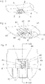
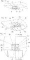
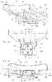
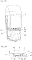
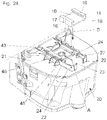
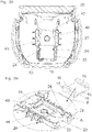
- Exemplary embodiments of a container according to the invention with a closure 10 with at least one recess 16 and/or a projection 26 on at least one of its outer surfaces 17, 18, 19 are in 23 to 36 shown.
- Figures 1 to 22 show non-inventive embodiments of a container with additional coding options.
- a container 1 made of soft, flexible material, for example thin plastic film, is approximately cuboid and has an opening 3 in a wall provided in particular with a reinforcing plate 13, which opening is provided within a tightly closable socket 2 or container neck. how 1 shows, the reinforcing plate 13 extends over a large part of the surface of the wall and encloses two opposite edges of the container 1 with side webs 14. Details about such a container 1 and its production are those mentioned in the introduction WO 2008/089500 refer to.
- the container 1 is intended in particular for holding liquid products such as disinfectants, shampoo, soap or the like, and is how 19 or 25 shows, inserted upside down in a dispenser 20, so that the wall provided with the reinforcing plate 13 and the socket 2 forms the standing side or the container bottom.
- the socket 2 carries, as in 2 shown in detail, a guide element 4, which is in the form of protruding webs 5 on both sides as an extension of its end face, and a sealing ring 7 which protrudes slightly from the end face is pushed onto the side, engaging behind the webs 5 with guide elements 11 .
- a guide elements 4, 11 comprehensive sliding guide on the socket 2 simplifies the insertion of the container 1 in the dispenser 20, from which to the other characters 3, 4 , 6 until 10 , and 12 until 16 only the only element essential for this purpose, namely the container receptacle 40 on the cover plate 21 of the lower part, is shown.
- This has an opening 46 which, when the container 1 is inserted and sealed by the sealing ring 7, is aligned with the socket 2 and the opening 3 of the container 1 ( 4 , 8th , 14 ).
- the container receptacle 40 on the cover plate 21 is structurally identical to the closure 10 with regard to the guide elements and can therefore also reach behind the webs 5 of the connecting piece 2 with its guide elements 41 when the container 1 is pushed into the container receptacle 40. this is in 6 indicated, in which the contour of the closure 10 is shown in dashed lines.
- the container 1 is therefore placed with the closure 10 on the container receptacle 40 in front of the guide elements 41 and then pushed in via the bevel 45 in the direction of arrow A, whereby the closure 10 is released, which remains in place at the attachment point, as in 7 is shown.
- coding is provided, ie the container and the container receptacle must be provided with elements that fit into one another.
- at least one projection 42 is provided on the container receptacle 40 and at least one corresponding clearance 6, 6' ( figure 5 , 11 , 17 ) provided, each in the sliding direction (arrow A) of the container 1 extend. If the correct container is inserted, align as shown in the 4 , 8th , 14 the openings 3 and 46 can be clearly seen. The insertion depth is limited by the depth of the exemption 6 and the length of the projection 42 and by a transverse web 44 on the container receptacle 40 .
- figure 5 shows the upper area of a container 1 with a nozzle 2, in which a central opening 6 is provided, into which the 6 shown central projection 42 engages.
- the cross-sections and lengths in the recess 6 and the projection 42 are the same. On average after 8 the inserted position is clearly visible, in which the openings 5 and 46 are aligned.
- the formation of a single central cut-out 6 is advantageous if only one installation position of the container 1 is desired. If the container 1 can also be used rotated by 180°, a second central clearance 6' is formed in the socket 2, which is rotated by 180° to the first, i.e. is diametrically opposite, as in 7 and 9 is shown.
- the connecting piece 2 thus has an H-shape in cross section.
- the projection 42 has a cross-sectional area composed of a rectangle followed by a triangle, just like each cut-out 6, 6′. If, despite two opposing clearances 6, 6', only one installation position of the container 1 is to be permitted in the dispenser, the closure 10 that fits this can have a projection that fits into the second clearance 6', so that the closure 10 can only be opened on this side .
- FIG 11 shows the upper area of a second embodiment of a container 1.
- the cutout 6 is not in the middle but on the side, and a corner area of the socket 2 is therefore missing the end 13 is evident.
- FIG. 12 shows the associated container receptacle 40, in which the projection 42 is also formed eccentrically in the corner area.
- the clearance 6 and the projection 42 have a trapezoidal cross-sectional area.
- 13 shows a horizontal section through the socket 2 of the container 1 inserted into the container receptacle, the socket 2 having been pushed in up to the stop 44 thanks to the cutout 6, so that the openings 3, 46 are aligned. This is again on average 14 evident.
- the exemptions 6, 6 ' are provided on the socket 2 below the webs 5 of the sliding guide, which thus extend over the entire depth or length.
- the in 17 shown embodiment extends the exemption 6 over the entire height of the socket 2, so that one of the two webs 5 is shortened. Since more than half of the web remains, neither the tight fit of the closure 10 on the neck 2 nor the fit of the neck 2 in the container receptacle 40 is impaired.
- the projection 42, the guide elements 41 and the crossbar 44 are advantageously provided on an insert 43 which, in adaptation to the containers to be used with this dispenser, is located in the cover plate 21 of the Lower part of the container 1 can be arranged.
- the exemplary embodiments described above offer protection against the use of conventional containers from other manufacturers, since the projection in the container receptacle requires recesses and clearances on the container which, if possible, cannot be formed subsequently.
- the container 1 (in 22 indicated) in turn has a reinforcing plate 13, which encloses two container edges with the opposite webs 14.
- Each web 14 has between one and six holes, which form the container 1 associated clearances 6, in which when the container 1 is pushed into the container receptacle 40 or its insert 43 between one and six projections 42 can occur.
- Figures 20 to 22 also show projections 12 in the form of webs, which protrude from socket 2 in the sliding direction (arrow A) and penetrate into a corresponding orientation or clearance 6, or a corresponding recess on the container receptacle 40 when the container 1 is inserted.
- webs 15 are arranged on the reinforcing plate 13, which extend in the sliding direction approximately over the second half of the sliding path until they are on the in 21 and 22 recognizable projection of the insert piece 43 in the form of a stop 47 abut. In this end position, the connecting piece 2 rests against the crossbar 44, the projection 12 has entered the clearance 6 and the opening 3 is aligned with the opening 46 of the container receptacle 40, not shown in these figures.
- the stop 47 is only on the left in the drawing Side formed and provided on the right side of the socket 2, the second web 15 does not hinder the insertion, since a stop 47 is missing on this side and thus there is also an exemption.
- a container receptacle 40 with one in the Figures 20 to 22 Insert piece 43 shown prevents the insertion of conventional containers only by the projections 42 and exemption 6 in the area of the upstanding webs 14, since no projections are provided which require exemptions on or in the socket 2. Stops 47 on the insert 43 or on the container receptacle 40 itself and webs 12 or 15 on the socket 2 and on the reinforcement plate 13 are mainly used to assign certain products to certain donors.
- FIG. 23 shows a second embodiment of a container 1 in an oblique view, onto the neck 2 of which a closure 10 is pushed, which is provided with a code.
- closure 10 shown in several embodiments, same as in the embodiments Figures 1 to 22 , an approximately C-shaped body with webs 11, which engage behind webs 5 on the socket 2, and has an upper side 19 parallel to the plane of the container opening 3, two side surfaces 17 lying in the sliding direction (arrow A) of the container 1 and two side surfaces lying perpendicular thereto 18 on.
- closures 10 which in at least one of the two side faces 17 have a recess 16 in the form of a groove that serves as coding.
- the groove 16 runs in the Figures 23 to 29 perpendicular to the plane of the container opening 3 and in 30 obliquely forward. How out 24 as can be seen, the depth of the groove preferably corresponds to the wall thickness, so that the web 5 of the socket 2 is exposed or is not cut out.
- Corresponding projections 24 in the form of lugs or ridges are provided as counter-elements to the recess 16 on the dispenser immediately in front of the container receptacle 40.
- a container 1 according to 23 can now be viewed either horizontally from the side ( 27 ), vertically from above ( 28 , 29 ) or diagonally from above ( 30 ) are inserted into the position in front of the container receptacle 40. This means an at least approximately or exactly L-shaped path, which is indicated by the two arrows B and A.
- the L-shaped path is parallel to the plane of the container opening 3 and to the plane of the opening 46 of the container receptacle 40 and the in 27
- the closure 10 shown - the container is not shown for the sake of clarity - arrives on the first path section corresponding to arrow B in the space forming a depot 23 in front of the container receptacle 40, with the projection 24 entering the recess 16 when the two coding elements match .
- the depot 23 is deeper than the container receptacle 40 by the thickness of the top of the closure 10, so that the container can be pushed further in the direction of arrow A, the closure 10 remaining in the depot 23 and the medium contained in the container 1 passing through the opening 3 and 46 can flow into the lower part of the dispenser 20.
- the depot 23 is delimited by webs 22 so that it receives the closure 10 in a form-fitting manner.
- the container 1 is pushed against the pushing direction when it is removed (arrow A) back onto the closure 10, and is then reclosed against the arrow B and removed from the dispenser.
- the container 1 can therefore also be exchanged when it is partially filled without a partial quantity being lost.
- the closed containers are lowered vertically from above (arrow B) and the closure 10 is again in the depot 23, as in 29 is shown, and the container can then be slid into the container receptacle 40 (arrow A).
- FIG. 30 shows the oblique arrangement of the coding elements 16 and 24, and thus also the oblique direction of insertion (arrow B) into the depot 23.
- the second part of the path is again indicated by the arrow A into the container receptacle 40.
- FIG. 27 , 28 and 30 each show an oblique view of the lower part of a dispenser 20 with the cover plate 21 on which the container receptacle 40, and an insert piece 43 accordingly Figures 20 to 22 is provided.
- the only difference is the transverse web 44 that is continuous across the width, so that the container to be used here is designed without projections. Likewise missing compared to the execution after Figures 20 to 22 the stop 47.
- FIG 31 and 32 show a closure 10 on which recesses 16 are provided in the narrow side surfaces 18, with recesses optionally also in the side surfaces according to FIG 23 possible are.
- the closure 10 shown can only be inserted into the depot 23 from above, so that it can be inserted from the side accordingly 27 omitted.
- the other two in 28 and 30 Possibilities shown are also with the closure 10 of 31 executable:
- the closed container is inserted between the delimiting webs 22 projecting upwards from the cover plate 21 into the depot 23, to which the container receptacle 40 adjoins, with the projections 24 entering the recesses 16.
- the container is now pushed further into the container receptacle 40, with the closure 10 remaining in the depot 23. If the container 1 is empty or still partially full and needs to be exchanged, it is pushed back into the depot 23, with the closure 10 blocked in this direction by the delimiting web 22 being pushed back onto the socket 2 and sealingly closing the container. The closed container is then removed.
- Figures 33 to 36 show coding elements on the top 19 of the closure 10, wherein according to Figure 33 the recesses 16 the form of cylindrical depressions, optionally also holes, and according to Figure 35 have the form of cylindrical projections 26.
- the corresponding counterparts are provided in the bottom surface of the depot 23, i.e. behind 34 the projections 28 shown in dashed lines are in the form of cylindrical knobs or the like, and in Figure 36 depressions 25, for example cylindrical blind holes, are formed in the cover 21.
- Projections 24, 27, 28 protruding into the depot 23 allow holes in the cover plate 21, which are covered by the projections 24, 27, 28, to explain the security against manipulation. If these projections of the depot 23 are removed, according to about container 1 1 without being able to use recess 16 in closure 10, these holes are exposed.
- a space (in particular an intermediate container, a pump chamber or the like) is preferably provided in the dispenser 20 below the cover 21, into which the liquid from the container 1 ( 19 ) flows out and which becomes leaky due to the removal of the projection 24.
- closure 10 is in each case cut parallel to the plane of the container opening 3, whereby the engagement of the projections 24 in the recess 16 can be seen more clearly.
- the sectional plane runs directly below the webs 11 of the closure 10.
- the projections 24 projecting into the depot 23 are divided horizontally, leaving a second projection 27 at the bottom of the depot 23 which, as mentioned above, exposes a hole in the cover when removed.
Landscapes
- Engineering & Computer Science (AREA)
- Mechanical Engineering (AREA)
- Health & Medical Sciences (AREA)
- Public Health (AREA)
- Closures For Containers (AREA)
- Containers And Packaging Bodies Having A Special Means To Remove Contents (AREA)
- Details Of Rigid Or Semi-Rigid Containers (AREA)
- Glass Compositions (AREA)
- Sheets, Magazines, And Separation Thereof (AREA)
Claims (18)
- Contenant qui est rempli d'un produit coulant du secteur sanitaire, de l'hygiène ou du soin, dans lequel le contenant (1) est réalisé comme recharge pouvant être posée sur la tête pour un système de distribution, dans lequel le contenant (1) présente une ouverture (3) se trouvant dans un plan et une fermeture (10) pouvant être retirée par coulissement dans le plan, dans lequel l'ouverture (3) est prévue au niveau d'une tubulure (2) du contenant (1), et dans lequel au moins un élément de guidage (4) est prévu au niveau de la tubulure (2), au niveau duquel ou dans lequel la fermeture (10) est coulissante par rapport au contenant (1), caractérisé en ce que la fermeture (10) présente au moins un évidement (16) et/ou une saillie (26) au niveau d'au moins une de ses surfaces extérieures (17, 18, 19).
- Contenant selon la revendication 1, dont la tubulure (2) présente des nervures (5) dépassant de part et d'autre comme éléments de guidage (4) pour la fermeture (10), dans lequel la fermeture (10) est un corps profilé à peu près en forme de C qui vient en prise derrière les nervures (5), caractérisé en ce qu'au moins un évidement (16) et/ou une saillie (26) est prévue dans au moins une des deux surfaces latérales (17) de la fermeture (10) s'étendant perpendiculairement au plan de l'ouverture de contenant (3) dans le sens de coulissement (flèche A) du contenant (1).
- Contenant selon la revendication 1 ou 2, caractérisé en ce qu'au moins un évidement (16) et/ou une saillie (26) est prévue dans au moins une surface latérale (18) de la fermeture (10) s'étendant perpendiculairement au plan de l'ouverture de contenant (3) et perpendiculairement au sens de coulissement (flèche A) du contenant (1).
- Contenant selon l'une quelconque des revendications 1 à 3, caractérisé en ce qu'au moins un évidement (16) et/ou une saillie (26) est réalisée dans une surface extérieure (19) s'étendant parallèlement au plan de l'ouverture de contenant (3) de la partie médiane de la fermeture (10).
- Contenant selon la revendication 2 ou 3, caractérisé en ce qu'un évidement (16) dans la surface latérale (17, 18) de la fermeture (10) est réalisé comme rainure orientée perpendiculairement au plan de l'ouverture de contenant (3).
- Contenant selon la revendication 2, caractérisé en ce qu'un évidement (16) est réalisé dans la surface latérale (17) de la fermeture (10) s'étendant dans le sens de coulissement (flèche A) du contenant (1) comme rainure orientée en biais par rapport au plan de l'ouverture de contenant (3).
- Contenant selon la revendication 4, caractérisé en ce qu'un évidement (16) est réalisé comme creux dans la surface extérieure (19) de la partie médiane de la fermeture (10).
- Contenant selon la revendication 7, caractérisé en ce que plusieurs creux sont agencés dans une trame.
- Contenant selon l'une quelconque des revendications 1 à 3, caractérisé en ce que deux évidements (16) et/ou saillies (26) rotatifs/rotatives de 180° sont prévu(e)s au niveau de la fermeture (10).
- Contenant selon l'une quelconque des revendications 1 à 5, caractérisé en ce qu'une languette accrochée par le biais d'un point de rupture à la fermeture est agencée de manière cassable pour la formation de l'évidement (16).
- Contenant selon la revendication 2 ou 3, caractérisé en ce qu'une saillie (26) est réalisée dans la surface latérale (17, 18) de la fermeture (10) comme nervure orientée perpendiculairement au plan de l'ouverture de contenant (3).
- Contenant selon la revendication 2, caractérisé en ce qu'une saillie (26) est réalisée dans la surface latérale (17) de la fermeture (10) s'étendant dans le sens de coulissement (flèche A) du contenant (1) comme nervure orientée en biais par rapport au plan de l'ouverture de contenant (3).
- Contenant selon la revendication 4, caractérisé en ce qu'une saillie (26) est réalisée comme téton au niveau de la surface extérieure (19) de la partie médiane de la fermeture (10).
- Contenant selon la revendication 13, caractérisé en ce que plusieurs tétons sont agencés dans une trame.
- Contenant selon l'une quelconque des revendications 1 à 14, caractérisé en ce que les surfaces extérieures (17, 18, 19) de la fermeture (10) sont planes et à angle droit les unes par rapport aux autres.
- Contenant selon l'une quelconque des revendications 1 à 15, caractérisé en ce que la surface extérieure (19) de la fermeture (10) s'étendant parallèlement au plan de l'ouverture de contenant (3) est rectangulaire, en particulier sensiblement carrée.
- Contenant selon l'une quelconque des revendications 1 à 16, caractérisé en ce que la fermeture (10) est coulissante jusqu'à la libération de l'ouverture.
- Contenant selon l'une quelconque des revendications 1 à 16, caractérisé en ce que la fermeture (10) peut être poussée entièrement depuis le dessous du contenant (1).
Priority Applications (5)
| Application Number | Priority Date | Filing Date | Title |
|---|---|---|---|
| SI201431964T SI3083440T1 (sl) | 2013-12-20 | 2014-12-15 | Vsebnik |
| RS20220564A RS63307B1 (sr) | 2013-12-20 | 2014-12-15 | Rezervoar |
| PL16182792T PL3115313T3 (pl) | 2013-12-20 | 2014-12-15 | Układ dozowania |
| EP16182792.8A EP3115313B1 (fr) | 2013-12-20 | 2014-12-15 | Système distributeur |
| HRP20220768TT HRP20220768T1 (hr) | 2013-12-20 | 2014-12-15 | Spremnik |
Applications Claiming Priority (2)
| Application Number | Priority Date | Filing Date | Title |
|---|---|---|---|
| ATA975/2013A AT515274B1 (de) | 2013-12-20 | 2013-12-20 | Behälter |
| PCT/AT2014/000222 WO2015089531A2 (fr) | 2013-12-20 | 2014-12-15 | Contenant |
Related Child Applications (2)
| Application Number | Title | Priority Date | Filing Date |
|---|---|---|---|
| EP16182792.8A Division-Into EP3115313B1 (fr) | 2013-12-20 | 2014-12-15 | Système distributeur |
| EP16182792.8A Division EP3115313B1 (fr) | 2013-12-20 | 2014-12-15 | Système distributeur |
Publications (2)
| Publication Number | Publication Date |
|---|---|
| EP3083440A2 EP3083440A2 (fr) | 2016-10-26 |
| EP3083440B1 true EP3083440B1 (fr) | 2022-03-30 |
Family
ID=52468853
Family Applications (2)
| Application Number | Title | Priority Date | Filing Date |
|---|---|---|---|
| EP16182792.8A Active EP3115313B1 (fr) | 2013-12-20 | 2014-12-15 | Système distributeur |
| EP14835687.6A Active EP3083440B1 (fr) | 2013-12-20 | 2014-12-15 | Conteneur |
Family Applications Before (1)
| Application Number | Title | Priority Date | Filing Date |
|---|---|---|---|
| EP16182792.8A Active EP3115313B1 (fr) | 2013-12-20 | 2014-12-15 | Système distributeur |
Country Status (20)
| Country | Link |
|---|---|
| US (2) | US10531769B2 (fr) |
| EP (2) | EP3115313B1 (fr) |
| CN (1) | CN105980261B (fr) |
| AT (1) | AT515274B1 (fr) |
| AU (2) | AU2014366863B2 (fr) |
| CA (1) | CA2934048C (fr) |
| EA (1) | EA034276B1 (fr) |
| ES (2) | ES2920900T3 (fr) |
| HR (2) | HRP20220768T1 (fr) |
| HU (2) | HUE058938T2 (fr) |
| IL (1) | IL246304B (fr) |
| ME (1) | ME03092B (fr) |
| MX (2) | MX378898B (fr) |
| PL (2) | PL3083440T3 (fr) |
| PT (2) | PT3115313T (fr) |
| RS (2) | RS57135B1 (fr) |
| SI (2) | SI3083440T1 (fr) |
| TR (1) | TR201806618T4 (fr) |
| WO (1) | WO2015089531A2 (fr) |
| ZA (1) | ZA201604117B (fr) |
Families Citing this family (3)
| Publication number | Priority date | Publication date | Assignee | Title |
|---|---|---|---|---|
| DE102017117557A1 (de) * | 2017-08-02 | 2019-02-07 | 3lmed GmbH | Applikationssystem |
| US10759647B1 (en) * | 2019-04-15 | 2020-09-01 | Plastic Technologies, Inc. | Method and device for dispensing from an inverted shippable container |
| AT523277B1 (de) | 2020-01-15 | 2021-07-15 | Georg Hagleitner Hans | Spender |
Family Cites Families (29)
| Publication number | Priority date | Publication date | Assignee | Title |
|---|---|---|---|---|
| US1897890A (en) * | 1931-03-23 | 1933-02-14 | Cook Ernest Harwood | Covering for container openings |
| US2370997A (en) * | 1943-05-10 | 1945-03-06 | Sidney J Rudolph | Receptacle and closure means therefor |
| US2436297A (en) * | 1944-07-25 | 1948-02-17 | Guarnaschelli Vincent | Bottle cap |
| FR1107608A (fr) * | 1954-06-19 | 1956-01-04 | Dispositif de fermeture pour bouteille | |
| US4570827A (en) * | 1984-03-28 | 1986-02-18 | Essex Chemical Corp. | Liquid dispenser |
| JPH0738089B2 (ja) * | 1988-11-30 | 1995-04-26 | 三田工業株式会社 | 現像剤容器 |
| US4942432A (en) * | 1989-06-28 | 1990-07-17 | Eastman Kodak Company | Apparatus for adding toner to an electrostatographic development station |
| JPH03245172A (ja) * | 1990-02-19 | 1991-10-31 | Nippon Kentek Kaisha Ltd | トナー補給容器及びトナー補給容器を固定する装置 |
| US5475479A (en) * | 1991-11-08 | 1995-12-12 | Canon Kabushiki Kaisha | Developer cartridge having an automatic lid closing mechanism |
| ZA932868B (en) * | 1992-04-24 | 1994-10-23 | Joseph C Mittel Jr | Closure device. |
| US5425404A (en) * | 1993-04-20 | 1995-06-20 | Minnesota Mining And Manufacturing Company | Gravity feed fluid dispensing system |
| JP2887046B2 (ja) * | 1993-06-25 | 1999-04-26 | キヤノン株式会社 | トナー補給装置とそれに使用されるトナーカートリッジ |
| WO1995009111A1 (fr) | 1993-09-28 | 1995-04-06 | Hagleitner Betriebshygiene Gesellschaft Mbh | Recipient en matiere thermoplastique et son procede de production |
| US5737675A (en) * | 1995-07-31 | 1998-04-07 | Mita Industrial Co. Ltd. | Toner supply device including toner cartridge and guide |
| DE29609142U1 (de) * | 1996-05-22 | 1996-08-14 | Dröppelmann, Thomas, 47608 Geldern | Verschluß für Dosen mit aufgefalztem Deckel |
| US6210638B1 (en) * | 1998-03-20 | 2001-04-03 | Jewel Precision | Plastic sterilization case |
| US6314262B1 (en) * | 1999-07-23 | 2001-11-06 | Sharp Kabushiki Kaisha | Toner supply system and toner cartridge |
| US6223791B1 (en) * | 1999-10-21 | 2001-05-01 | 3M Innovative Properties Company | Gravity feed fluid dispensing valve |
| US6212721B1 (en) * | 2000-04-17 | 2001-04-10 | German Borodulin | Opener and stopper for crimped and threaded bottle caps |
| US6868988B2 (en) * | 2003-02-28 | 2005-03-22 | Nestec S.A. | Containers of flowable substance adapted for connecting to dispensing devices of a beverage or food dispensing machine |
| FR2862618B1 (fr) * | 2003-11-24 | 2007-04-13 | Pierre Malek | Dispositif de rangement d'outils a declipsage de couvercle |
| US7043173B2 (en) * | 2004-02-27 | 2006-05-09 | Grune Guerry L | Toner hopper engagement device, a toner container, and a toner refill kit |
| ES2298925T3 (es) | 2005-05-03 | 2008-05-16 | Johnsondiversey, Inc. | Aparato dispensador de jabon. |
| EP1950148B1 (fr) * | 2007-01-23 | 2009-10-14 | Hans Georg Hagleitner | Récipient formé à partir d'une bande de matériau flexible en plastique soudable |
| US7832595B2 (en) * | 2007-07-23 | 2010-11-16 | Conopco, Inc. | Household liquid dispenser with keyed spout fitment and refill |
| US8657136B2 (en) * | 2010-03-22 | 2014-02-25 | Wyeth Llc | Child resistant bulk dose dispensing unit |
| CN201971310U (zh) * | 2010-12-22 | 2011-09-14 | 浙江省磐安县绿海工艺厂 | 磁力扣画盒 |
| CN202022412U (zh) * | 2011-03-31 | 2011-11-02 | 天津中野塑料制品有限公司 | 防尘防潮箱盖 |
| DE102011120820B4 (de) | 2011-12-13 | 2014-05-08 | Metsä Tissue Oyj | Haltevorrichtung für einen Behälter für insbesondere flüssige Produkte |
-
2013
- 2013-12-20 AT ATA975/2013A patent/AT515274B1/de not_active IP Right Cessation
-
2014
- 2014-12-15 HU HUE14835687A patent/HUE058938T2/hu unknown
- 2014-12-15 ES ES14835687T patent/ES2920900T3/es active Active
- 2014-12-15 EP EP16182792.8A patent/EP3115313B1/fr active Active
- 2014-12-15 PL PL14835687.6T patent/PL3083440T3/pl unknown
- 2014-12-15 CA CA2934048A patent/CA2934048C/fr active Active
- 2014-12-15 HU HUE16182792A patent/HUE037526T2/hu unknown
- 2014-12-15 HR HRP20220768TT patent/HRP20220768T1/hr unknown
- 2014-12-15 SI SI201431964T patent/SI3083440T1/sl unknown
- 2014-12-15 RS RS20180475A patent/RS57135B1/sr unknown
- 2014-12-15 ME MEP-2018-114A patent/ME03092B/fr unknown
- 2014-12-15 MX MX2016008236A patent/MX378898B/es unknown
- 2014-12-15 PL PL16182792T patent/PL3115313T3/pl unknown
- 2014-12-15 CN CN201480075132.9A patent/CN105980261B/zh active Active
- 2014-12-15 SI SI201430691T patent/SI3115313T1/en unknown
- 2014-12-15 EA EA201691296A patent/EA034276B1/ru not_active IP Right Cessation
- 2014-12-15 AU AU2014366863A patent/AU2014366863B2/en active Active
- 2014-12-15 RS RS20220564A patent/RS63307B1/sr unknown
- 2014-12-15 WO PCT/AT2014/000222 patent/WO2015089531A2/fr not_active Ceased
- 2014-12-15 EP EP14835687.6A patent/EP3083440B1/fr active Active
- 2014-12-15 PT PT161827928T patent/PT3115313T/pt unknown
- 2014-12-15 TR TR2018/06618T patent/TR201806618T4/tr unknown
- 2014-12-15 PT PT148356876T patent/PT3083440T/pt unknown
- 2014-12-15 ES ES16182792.8T patent/ES2668954T3/es active Active
-
2016
- 2016-06-17 ZA ZA2016/04117A patent/ZA201604117B/en unknown
- 2016-06-19 IL IL246304A patent/IL246304B/en active IP Right Grant
- 2016-06-20 US US15/187,143 patent/US10531769B2/en active Active
- 2016-06-20 MX MX2020003814A patent/MX2020003814A/es unknown
-
2017
- 2017-05-15 AU AU2017203219A patent/AU2017203219B2/en active Active
-
2018
- 2018-05-04 HR HRP20180700TT patent/HRP20180700T1/hr unknown
-
2019
- 2019-11-08 US US16/677,766 patent/US11058262B2/en active Active
Also Published As
Similar Documents
| Publication | Publication Date | Title |
|---|---|---|
| DE3779685T2 (de) | Abgabebehaelter. | |
| DE3806338C2 (de) | Spendebehälter zur getrennten Aufbewahrung und wahlweisen Abgabe zweier fließfähiger Materialien | |
| DE69422976T2 (de) | Ausgabevorrichtung versehen mit einem Rückschlagventil | |
| DE69807838T2 (de) | Verpackungs- und Abgabeeinheit und Verwendung einer solchen Einheit zur Verpackung von kosmetischen, pharmazeutischen oder dermopharmazeutischen Produkten | |
| DE69307836T2 (de) | Misch und ausgabebehälter mit zwei kammern | |
| DE29514137U1 (de) | Tablettenspender | |
| DE3017376A1 (de) | Behaeltnis zur einzel-portionierten ausgabe von tabletten | |
| EP3115313B1 (fr) | Système distributeur | |
| AT522212A1 (de) | Spenderset mit einer Ausgabevorrichtung und mindestens einem ein pumpfähiges Medium enthaltenden Behälter | |
| EP3083441B1 (fr) | Contenant | |
| EP0241632B1 (fr) | Conteneur pour recevoir un emballage contenant un liquide | |
| EP1280706B1 (fr) | Boite d'emballage pour comprimes | |
| DE602004004795T2 (de) | Fluidproduktabgabekopf | |
| EP0786420A2 (fr) | Distributeur de comprimés pour la distribution individuelle de comprimés | |
| WO2005006931A1 (fr) | Distributeur pour des milieux liquides ou pateux | |
| DE3544748A1 (de) | Vorrichtung zur dosierten ausgabe von fliessfaehigen medien | |
| EP3851003B1 (fr) | Distributeur | |
| DE4003567A1 (de) | Behaelter zum aufbewahren und transportieren, insbesondere von kleinen empfindlichen guetern | |
| EP2631193B1 (fr) | Fermeture coulissante pour un récipient | |
| EP2431294B1 (fr) | Fermeture rotative pour récipients cosmétiques | |
| EP4387497A1 (fr) | Distributeur pour distribuer un matériau de type feuille et contenant pour matériau de type feuille | |
| EP1571101B1 (fr) | Dispositif de stockage et de distribution de fluide | |
| DE29907879U1 (de) | Spender für ein körniges oder pulverförmiges Nahrungsmittel, insbesondere Zucker- oder Kaffee-Spender | |
| DE3724998A1 (de) | Gewuerzspenderanordnung | |
| DE8623632U1 (de) | Gewürzspenderanordnung |
Legal Events
| Date | Code | Title | Description |
|---|---|---|---|
| REG | Reference to a national code |
Ref country code: HR Ref legal event code: TUEP Ref document number: P20220768T Country of ref document: HR |
|
| PUAI | Public reference made under article 153(3) epc to a published international application that has entered the european phase |
Free format text: ORIGINAL CODE: 0009012 |
|
| 17P | Request for examination filed |
Effective date: 20160628 |
|
| AK | Designated contracting states |
Kind code of ref document: A2 Designated state(s): AL AT BE BG CH CY CZ DE DK EE ES FI FR GB GR HR HU IE IS IT LI LT LU LV MC MK MT NL NO PL PT RO RS SE SI SK SM TR |
|
| AX | Request for extension of the european patent |
Extension state: BA ME |
|
| STAA | Information on the status of an ep patent application or granted ep patent |
Free format text: STATUS: EXAMINATION IS IN PROGRESS |
|
| 17Q | First examination report despatched |
Effective date: 20210326 |
|
| GRAP | Despatch of communication of intention to grant a patent |
Free format text: ORIGINAL CODE: EPIDOSNIGR1 |
|
| STAA | Information on the status of an ep patent application or granted ep patent |
Free format text: STATUS: GRANT OF PATENT IS INTENDED |
|
| INTG | Intention to grant announced |
Effective date: 20211129 |
|
| GRAS | Grant fee paid |
Free format text: ORIGINAL CODE: EPIDOSNIGR3 |
|
| GRAA | (expected) grant |
Free format text: ORIGINAL CODE: 0009210 |
|
| STAA | Information on the status of an ep patent application or granted ep patent |
Free format text: STATUS: THE PATENT HAS BEEN GRANTED |
|
| AK | Designated contracting states |
Kind code of ref document: B1 Designated state(s): AL AT BE BG CH CY CZ DE DK EE ES FI FR GB GR HR HU IE IS IT LI LT LU LV MC MK MT NL NO PL PT RO RS SE SI SK SM TR |
|
| REG | Reference to a national code |
Ref country code: GB Ref legal event code: FG4D Free format text: NOT ENGLISH |
|
| REG | Reference to a national code |
Ref country code: CH Ref legal event code: EP |
|
| REG | Reference to a national code |
Ref country code: DE Ref legal event code: R096 Ref document number: 502014016173 Country of ref document: DE |
|
| REG | Reference to a national code |
Ref country code: AT Ref legal event code: REF Ref document number: 1479014 Country of ref document: AT Kind code of ref document: T Effective date: 20220415 |
|
| REG | Reference to a national code |
Ref country code: IE Ref legal event code: FG4D Free format text: LANGUAGE OF EP DOCUMENT: GERMAN |
|
| REG | Reference to a national code |
Ref country code: PT Ref legal event code: SC4A Ref document number: 3083440 Country of ref document: PT Date of ref document: 20220614 Kind code of ref document: T Free format text: AVAILABILITY OF NATIONAL TRANSLATION Effective date: 20220603 |
|
| REG | Reference to a national code |
Ref country code: RO Ref legal event code: EPE |
|
| REG | Reference to a national code |
Ref country code: FI Ref legal event code: FGE |
|
| REG | Reference to a national code |
Ref country code: LT Ref legal event code: MG9D |
|
| REG | Reference to a national code |
Ref country code: NL Ref legal event code: FP |
|
| REG | Reference to a national code |
Ref country code: SE Ref legal event code: TRGR |
|
| PG25 | Lapsed in a contracting state [announced via postgrant information from national office to epo] |
Ref country code: NO Free format text: LAPSE BECAUSE OF FAILURE TO SUBMIT A TRANSLATION OF THE DESCRIPTION OR TO PAY THE FEE WITHIN THE PRESCRIBED TIME-LIMIT Effective date: 20220630 Ref country code: LT Free format text: LAPSE BECAUSE OF FAILURE TO SUBMIT A TRANSLATION OF THE DESCRIPTION OR TO PAY THE FEE WITHIN THE PRESCRIBED TIME-LIMIT Effective date: 20220330 |
|
| REG | Reference to a national code |
Ref country code: ES Ref legal event code: FG2A Ref document number: 2920900 Country of ref document: ES Kind code of ref document: T3 Effective date: 20220811 |
|
| PG25 | Lapsed in a contracting state [announced via postgrant information from national office to epo] |
Ref country code: LV Free format text: LAPSE BECAUSE OF FAILURE TO SUBMIT A TRANSLATION OF THE DESCRIPTION OR TO PAY THE FEE WITHIN THE PRESCRIBED TIME-LIMIT Effective date: 20220330 Ref country code: GR Free format text: LAPSE BECAUSE OF FAILURE TO SUBMIT A TRANSLATION OF THE DESCRIPTION OR TO PAY THE FEE WITHIN THE PRESCRIBED TIME-LIMIT Effective date: 20220701 |
|
| REG | Reference to a national code |
Ref country code: HR Ref legal event code: T1PR Ref document number: P20220768 Country of ref document: HR |
|
| REG | Reference to a national code |
Ref country code: HU Ref legal event code: AG4A Ref document number: E058938 Country of ref document: HU |
|
| PG25 | Lapsed in a contracting state [announced via postgrant information from national office to epo] |
Ref country code: SM Free format text: LAPSE BECAUSE OF FAILURE TO SUBMIT A TRANSLATION OF THE DESCRIPTION OR TO PAY THE FEE WITHIN THE PRESCRIBED TIME-LIMIT Effective date: 20220330 Ref country code: EE Free format text: LAPSE BECAUSE OF FAILURE TO SUBMIT A TRANSLATION OF THE DESCRIPTION OR TO PAY THE FEE WITHIN THE PRESCRIBED TIME-LIMIT Effective date: 20220330 |
|
| PG25 | Lapsed in a contracting state [announced via postgrant information from national office to epo] |
Ref country code: IS Free format text: LAPSE BECAUSE OF FAILURE TO SUBMIT A TRANSLATION OF THE DESCRIPTION OR TO PAY THE FEE WITHIN THE PRESCRIBED TIME-LIMIT Effective date: 20220730 Ref country code: AL Free format text: LAPSE BECAUSE OF FAILURE TO SUBMIT A TRANSLATION OF THE DESCRIPTION OR TO PAY THE FEE WITHIN THE PRESCRIBED TIME-LIMIT Effective date: 20220330 |
|
| REG | Reference to a national code |
Ref country code: HR Ref legal event code: ODRP Ref document number: P20220768 Country of ref document: HR Payment date: 20221125 Year of fee payment: 9 |
|
| REG | Reference to a national code |
Ref country code: DE Ref legal event code: R097 Ref document number: 502014016173 Country of ref document: DE |
|
| PG25 | Lapsed in a contracting state [announced via postgrant information from national office to epo] |
Ref country code: DK Free format text: LAPSE BECAUSE OF FAILURE TO SUBMIT A TRANSLATION OF THE DESCRIPTION OR TO PAY THE FEE WITHIN THE PRESCRIBED TIME-LIMIT Effective date: 20220330 |
|
| PLBE | No opposition filed within time limit |
Free format text: ORIGINAL CODE: 0009261 |
|
| STAA | Information on the status of an ep patent application or granted ep patent |
Free format text: STATUS: NO OPPOSITION FILED WITHIN TIME LIMIT |
|
| 26N | No opposition filed |
Effective date: 20230103 |
|
| P01 | Opt-out of the competence of the unified patent court (upc) registered |
Effective date: 20230612 |
|
| P02 | Opt-out of the competence of the unified patent court (upc) changed |
Effective date: 20230621 |
|
| REG | Reference to a national code |
Ref country code: BE Ref legal event code: MM Effective date: 20221231 |
|
| PG25 | Lapsed in a contracting state [announced via postgrant information from national office to epo] |
Ref country code: LU Free format text: LAPSE BECAUSE OF NON-PAYMENT OF DUE FEES Effective date: 20221215 |
|
| PG25 | Lapsed in a contracting state [announced via postgrant information from national office to epo] |
Ref country code: IE Free format text: LAPSE BECAUSE OF NON-PAYMENT OF DUE FEES Effective date: 20221215 |
|
| PG25 | Lapsed in a contracting state [announced via postgrant information from national office to epo] |
Ref country code: BE Free format text: LAPSE BECAUSE OF NON-PAYMENT OF DUE FEES Effective date: 20221231 |
|
| REG | Reference to a national code |
Ref country code: HR Ref legal event code: ODRP Ref document number: P20220768 Country of ref document: HR Payment date: 20231124 Year of fee payment: 10 |
|
| PG25 | Lapsed in a contracting state [announced via postgrant information from national office to epo] |
Ref country code: CY Free format text: LAPSE BECAUSE OF FAILURE TO SUBMIT A TRANSLATION OF THE DESCRIPTION OR TO PAY THE FEE WITHIN THE PRESCRIBED TIME-LIMIT Effective date: 20220330 |
|
| PG25 | Lapsed in a contracting state [announced via postgrant information from national office to epo] |
Ref country code: MK Free format text: LAPSE BECAUSE OF FAILURE TO SUBMIT A TRANSLATION OF THE DESCRIPTION OR TO PAY THE FEE WITHIN THE PRESCRIBED TIME-LIMIT Effective date: 20220330 |
|
| PG25 | Lapsed in a contracting state [announced via postgrant information from national office to epo] |
Ref country code: MC Free format text: LAPSE BECAUSE OF FAILURE TO SUBMIT A TRANSLATION OF THE DESCRIPTION OR TO PAY THE FEE WITHIN THE PRESCRIBED TIME-LIMIT Effective date: 20220330 |
|
| PG25 | Lapsed in a contracting state [announced via postgrant information from national office to epo] |
Ref country code: MC Free format text: LAPSE BECAUSE OF FAILURE TO SUBMIT A TRANSLATION OF THE DESCRIPTION OR TO PAY THE FEE WITHIN THE PRESCRIBED TIME-LIMIT Effective date: 20220330 |
|
| PG25 | Lapsed in a contracting state [announced via postgrant information from national office to epo] |
Ref country code: MT Free format text: LAPSE BECAUSE OF FAILURE TO SUBMIT A TRANSLATION OF THE DESCRIPTION OR TO PAY THE FEE WITHIN THE PRESCRIBED TIME-LIMIT Effective date: 20220330 |
|
| REG | Reference to a national code |
Ref country code: HR Ref legal event code: ODRP Ref document number: P20220768 Country of ref document: HR Payment date: 20241113 Year of fee payment: 11 |
|
| PGFP | Annual fee paid to national office [announced via postgrant information from national office to epo] |
Ref country code: PT Payment date: 20251114 Year of fee payment: 12 |
|
| REG | Reference to a national code |
Ref country code: HR Ref legal event code: ODRP Ref document number: P20220768 Country of ref document: HR Payment date: 20251114 Year of fee payment: 12 |
|
| REG | Reference to a national code |
Ref country code: CH Ref legal event code: U11 Free format text: ST27 STATUS EVENT CODE: U-0-0-U10-U11 (AS PROVIDED BY THE NATIONAL OFFICE) Effective date: 20260101 |
|
| PGFP | Annual fee paid to national office [announced via postgrant information from national office to epo] |
Ref country code: GB Payment date: 20251223 Year of fee payment: 12 |
|
| PGFP | Annual fee paid to national office [announced via postgrant information from national office to epo] |
Ref country code: AT Payment date: 20251223 Year of fee payment: 12 |
|
| PGFP | Annual fee paid to national office [announced via postgrant information from national office to epo] |
Ref country code: IT Payment date: 20251218 Year of fee payment: 12 Ref country code: FI Payment date: 20251222 Year of fee payment: 12 |
|
| PGFP | Annual fee paid to national office [announced via postgrant information from national office to epo] |
Ref country code: HR Payment date: 20251114 Year of fee payment: 12 Ref country code: HU Payment date: 20251118 Year of fee payment: 12 Ref country code: NL Payment date: 20251222 Year of fee payment: 12 Ref country code: FR Payment date: 20251223 Year of fee payment: 12 |
|
| PGFP | Annual fee paid to national office [announced via postgrant information from national office to epo] |
Ref country code: TR Payment date: 20251126 Year of fee payment: 12 |
|
| PGFP | Annual fee paid to national office [announced via postgrant information from national office to epo] |
Ref country code: SE Payment date: 20251128 Year of fee payment: 12 |
|
| PGFP | Annual fee paid to national office [announced via postgrant information from national office to epo] |
Ref country code: CZ Payment date: 20251112 Year of fee payment: 12 |
|
| PGFP | Annual fee paid to national office [announced via postgrant information from national office to epo] |
Ref country code: PL Payment date: 20251113 Year of fee payment: 12 Ref country code: BG Payment date: 20251223 Year of fee payment: 12 |
|
| PGFP | Annual fee paid to national office [announced via postgrant information from national office to epo] |
Ref country code: RO Payment date: 20251203 Year of fee payment: 12 Ref country code: SK Payment date: 20251114 Year of fee payment: 12 |
|
| PGFP | Annual fee paid to national office [announced via postgrant information from national office to epo] |
Ref country code: RS Payment date: 20251114 Year of fee payment: 12 |
|
| PGFP | Annual fee paid to national office [announced via postgrant information from national office to epo] |
Ref country code: SI Payment date: 20251113 Year of fee payment: 12 |
|
| PGFP | Annual fee paid to national office [announced via postgrant information from national office to epo] |
Ref country code: ES Payment date: 20260122 Year of fee payment: 12 |
|
| PGFP | Annual fee paid to national office [announced via postgrant information from national office to epo] |
Ref country code: DE Payment date: 20251229 Year of fee payment: 12 |
|
| PGFP | Annual fee paid to national office [announced via postgrant information from national office to epo] |
Ref country code: CH Payment date: 20260101 Year of fee payment: 12 |