EP3084097B1 - Konstruktion und verfahren zur herstellung einer konstruktion - Google Patents
Konstruktion und verfahren zur herstellung einer konstruktion Download PDFInfo
- Publication number
- EP3084097B1 EP3084097B1 EP14816247.2A EP14816247A EP3084097B1 EP 3084097 B1 EP3084097 B1 EP 3084097B1 EP 14816247 A EP14816247 A EP 14816247A EP 3084097 B1 EP3084097 B1 EP 3084097B1
- Authority
- EP
- European Patent Office
- Prior art keywords
- duct
- ducts
- construction
- elements
- link
- Prior art date
- Legal status (The legal status is an assumption and is not a legal conclusion. Google has not performed a legal analysis and makes no representation as to the accuracy of the status listed.)
- Not-in-force
Links
Images


Classifications
-
- E—FIXED CONSTRUCTIONS
- E04—BUILDING
- E04C—STRUCTURAL ELEMENTS; BUILDING MATERIALS
- E04C5/00—Reinforcing elements, e.g. for concrete; Auxiliary elements therefor
- E04C5/08—Members specially adapted to be used in prestressed constructions
- E04C5/10—Ducts
-
- E—FIXED CONSTRUCTIONS
- E04—BUILDING
- E04C—STRUCTURAL ELEMENTS; BUILDING MATERIALS
- E04C5/00—Reinforcing elements, e.g. for concrete; Auxiliary elements therefor
- E04C5/08—Members specially adapted to be used in prestressed constructions
-
- E—FIXED CONSTRUCTIONS
- E04—BUILDING
- E04C—STRUCTURAL ELEMENTS; BUILDING MATERIALS
- E04C5/00—Reinforcing elements, e.g. for concrete; Auxiliary elements therefor
- E04C5/16—Auxiliary parts for reinforcements, e.g. connectors, spacers, stirrups
- E04C5/162—Connectors or means for connecting parts for reinforcements
-
- F—MECHANICAL ENGINEERING; LIGHTING; HEATING; WEAPONS; BLASTING
- F16—ENGINEERING ELEMENTS AND UNITS; GENERAL MEASURES FOR PRODUCING AND MAINTAINING EFFECTIVE FUNCTIONING OF MACHINES OR INSTALLATIONS; THERMAL INSULATION IN GENERAL
- F16L—PIPES; JOINTS OR FITTINGS FOR PIPES; SUPPORTS FOR PIPES, CABLES OR PROTECTIVE TUBING; MEANS FOR THERMAL INSULATION IN GENERAL
- F16L9/00—Rigid pipes
- F16L9/08—Rigid pipes of concrete, cement, or asbestos cement, with or without reinforcement
Definitions
- the present invention relates to a construction such as a building, a bridge, a road, or a wall etc., comprising at least two elements, each element comprising at least one through-going duct.
- the invention further relates to a method of making a construction by assembling at least two elements.
- Precast concrete elements for constructions, bridges, roads, harbours, and other construction work are increasingly used in modern construction work.
- constructions comprising at least two elements are constructed by arranging the two elements adjacently, or on top of each other. The elements are joined by use of concrete. To form the concrete into a desired shape, and to keep the concrete in place until the setting of the concrete is complete, a formwork is made.
- the formwork is made on location and due to difficult accessibility or large tolerances etc., the formwork seldom match exactly to the shape of the precast concrete elements which are to be joined. Typically the concrete therefore escapes the formwork and leaks to unwanted positions. This introduces an increased consumption of concrete and may potentially cause large expenses for removing concrete which has escaped the formwork.
- Prior art document US 2010/0088985 discloses a pre-stressed building structure comprising an assembly of precast elements separated by gaps occupied by an interface product, one or more pre-stressing sheaths having sections respectively incorporated into the precast elements, and a pre-stressing tendon tensioned inside the sheath.
- the sheath sections are respectively fitted with first and second end pieces opening out on the facing surfaces of the two precast elements.
- the first end piece has a flared opening.
- An elastic connecting sleeve is connected in a sealed manner to the second end piece. The sleeve presses against the first end piece, which compresses it longitudinally to ensure a seal between the inside of the sheath sections and the gap separating the adjacent surfaces of the two elements.
- Prior art document AU 53792 69 discloses a method of forming a duct between two existing ducts by employing a telescopic tube formed from two relatively movable tubular parts having a seal between them. The telescopic tube is inserted in the ducts after alignment of the ducts.
- the invention provides a construction according to claim 1.
- the two ducts may be connected in a cost efficient manner, and by forming an uninterrupted duct from the first end to the fourth end, formwork becomes unnecessary.
- formwork becomes unnecessary.
- the tubular link can be made entirely prefabricated, and ad hoc, on location formwork becomes unnecessary.
- duct should be understood as, a tubular element, such as a tube, being elongated and having an opening at each end.
- the duct may have a substantially circular cross-section.
- ducts having another cross-section, such as an oval cross-section are also covered by the term "duct".
- the duct may be made in one piece, or may be made from a plurality of duct elements which may be joined by overlapping sections, may be butt joined, or may be otherwise joined.
- a substantially liquid tight duct may be formed through the first and second elements.
- the uninterrupted duct may also be substantially airtight.
- the first and second elements may be used for several types of constructions, such as walls, decks, foundations, bridges, ramps, tunnels, etc.
- the elements may be precast, or in-situ cast.
- the first and second elements may be arranged vertically above each other e.g. when constructing a wall, a ramp, a tunnel, and the like, or alternatively horizontally next to each other e.g. when constructing a deck or a bridge, or constructing a wall, thereby resulting in either vertically positioned or horizontally positioned ducts. It should however be understood, that at least one of the elements may also be positioned with an inclination, such as at an angle of e.g. 5, 10, or 15 degrees, or any other degree, thereby providing at least one inclined duct.
- the first element may be arranged vertically, whereas the second element positioned on top of this first element may be arranged at an angle relative to the first element, whereby the first and second ducts are angled relative to each other, thereby forming an uninterrupted duct having at least one break, i.e. an uninterrupted duct which is not linear.
- the lower opening in the upper duct i.e. the duct opening facing downwards towards the element positioned below, may be arranged in a recess in the upper free end of the lower element.
- a recess may likewise be formed in at least one of these.
- a recess can be either in the upper free end of the lower element, or, in the lower free end of the upper element.
- the first and second elements are arranged so that the second end faces the third end.
- the distance between the two ends may depend on the construction to be provided, the size of the construction, the size of the elements, the size of the ducts, and other parameters. It should however be understood, that the invention is equally applicable for constructions in which the second end faces the fourth end and in which the first end faces the third end.
- the first and second ducts are arranged to provide communication there between via the tubular link. This may be achieved by aligning the ducts.
- aligned is herein meant, that the opening in the first element is at least partly overlapping the opening in the second element when viewed in parallel to the element.
- communication may also be achieved when the first duct and the second duct are not aligned. In the latter case, the flexibility of the tubular link may ensure communication between the first and second ducts thereby providing an uninterrupted duct from the first end to the fourth end.
- body of a flexible material should be understood as a body having a shape which is easily reshaped during intended handling thereby allowing easy and quick reshaping to adapt the body to a first duct and a second duct not being aligned, or being arranged so that the openings partly overlap. It could e.g. be a flex hose.
- the first and second elements may be precast concrete elements.
- the first and second ducts may be metal ducts which are cast into the elements at the precast plant.
- the ducts may be made from sheet metal having a plane surface or alternatively a corrugated surface. The latter may improve the ability of the concrete to stick to the ducts thereby facilitating the adherence of the concrete. It should however be understood, that the ducts may also be made of polymer material having a smooth or corrugated surface, or another material suitable for being cast into or otherwise arranged in the first and second elements.
- the first and second elements may comprise one duct each. It should however be understood, that at least one of the elements may comprise a plurality of ducts.
- the diameter of the ducts may depend on the construction to be provided, the size of the construction, the size of the elements, etc.
- the ducts may be provided with equal diameter.
- the diameter of the first duct may be different from the diameter of the second duct.
- the diameter of the tubular link may be substantially equal to the diameter of the first duct at one end of the link, whereas the diameter of the tubular link may be substantially equal to the diameter of the second duct at the other end of the tubular link.
- the cross-sectional shape of the ducts and the link may be substantially circular. It should however, be understood that the shape may alternatively be oval or in other ways form a shape being different from circular.
- the tubular link comprises a body of a flexible material
- the cross-sectional shape of this body may change along the length of the body, e.g. be due to a pressure on the body during positioning of the tubular link.
- the construction may further comprise a third element extending between a fifth and a sixth opposite free end and comprising a third duct forming an opening in each of the fifth and sixth free ends.
- the third element may be arranged so that the fifth end is facing the fourth end.
- a second tubular link may be arranged to provide communication between the third duct and one of the first and second ducts, to thereby provide an uninterrupted duct from the first end to the sixth end.
- the order of the three elements may be chosen differently, as the third element as an example may be positioned between the first and second elements or next to or above/below the first element instead of next to or above/below the second element.
- the construction may comprise more elements, such as four, five, six, or even more elements arranged next to each other, or above or below each other.
- the link may further comprise at least one non-flexible transition part attachable to one end of the body and forming a socket to be received in one of the ducts.
- the link may comprise two non-flexible transition parts, each being attachable to an end of the body to provide a link comprising two non-flexible transition parts with a flexible body there between.
- the non-flexible transition part(s) may be formed of metal, such as steel, and may have a substantially circular cross-section with a diameter being less than the diameter of the duct(s) to facilitate insertion of the transition part into the duct.
- Other materials, such as polymer material, may also be used.
- non-flexible transition part should be understood as a part having a shape which is maintained during intended handling. I.e. it is not intended to be deformed during use.
- the construction may also be made without the two non-flexible transition parts by arranging the tubular link with a body of a flexible material without the non-flexible parts to thereby provide an uninterrupted duct without the non-flexible transition parts. This may be done by arranging each of the opposites ends of the body inside the first and second ducts, respectively, or by extending each of the first and second ducts so that they protrude from the first and second elements, respectively and attaching the tubular link with the flexible body to these protrusions.
- the link which is arranged to provide communication between the first and second ducts may be positioned solely by inserting the non-flexible transition part(s) into the duct(s) or by inserting the flexible body itself into the duct(s).
- the link may however comprise a locking structure for locking of the link to at least one of the ducts.
- the locking structure may e.g. be an O-ring of a flexible material adapted to ensure fixing of the link to the duct.
- the link and the duct may be clamped together e.g. by use of a hose clamp.
- the link may be bonded to the first and/or second duct by use of an adhesive.
- Other locking structures, such as a treaded structure, may also be applied.
- the non-flexible transition part(s) may likewise be adhered to the body, or may be attached by use of a hose clamp or an O-ring. It should however be understood, that other ways of attachment of non-flexible part may also be applicable. In one embodiment, the non-flexible transition part may be detachable attached to the body thereby providing a possibility of subsequently separating the part from the body, if required.
- At least one of the elements may be provided with an elongated reinforcement structure along the length of the element in order to strengthen the element.
- an elongated reinforcement structure may extend through the link and the first and second ducts, i.e. extend through the uninterrupted duct from the first to the fourth end.
- the reinforcement structure may as an example comprise at least one cable or an elongated tensile element.
- the reinforcement structure may comprise a rod.
- Other types of reinforcement structures may also be used.
- the reinforcement structure may be made from steel, or a material of similar strength.
- an elongated reinforcement structure may extend through each of the links and each of the ducts, whereby the reinforcement structure extends through the uninterrupted duct from one free end to the opposite free end.
- the reinforcement structure may extend through the links and the first, second, and third ducts.
- the elongated reinforcement structure may comprises a plurality of reinforcement elements, such a plurality of cables running in parallel or being coiled.
- One or more of the reinforcement elements may extend through all the elements, whereas one or more of the other reinforcement elements may only extend through one or some of the elements.
- the reinforcement structure may be stressed after positioning hereof. Stressing of the reinforcement structure may be carried out only for one or more of a plurality of reinforcement elements, and not necessarily for each of the reinforcement elements.
- the uninterrupted duct may be filled with a filling material, such as injection mortar or another easily floating mortar.
- the filling material may be expandable. If the duct comprises a reinforcement structure, the filling material may support this reinforcement structure and ensure that the reinforcement structure is kept in place, and prevent deformation of the reinforcement structure, thus acting as a locking structure for the reinforcement structure.
- mortar is an example of a filling material.
- the filling material may be any material that can fill the voided space inside the duct.
- At least a part of the elongated reinforcement structure may be located in an elongated shielding, such as an elongated tube encircling the reinforcement structure.
- an elongated shielding such as an elongated tube encircling the reinforcement structure.
- the construction comprises a plurality of elongated reinforcement elements being located in a shielding, it should be understood, that these elements may each be located in a shielding. However, some of the elongated reinforcement elements may also be located in a common shielding.
- the joint may further be able to take up sheer forces, thereby increasing the strength of the construction further.
- this material may further act as corrosion protection of the reinforcement structure, e.g. by providing an air tight barrier.
- the invention provides a method of making a construction according to claim 11.
- the method may further comprising a step of arranging a reinforcement structure so that it extends from the fourth end to the first end through the link and the first and second ducts. After arrangement of the reinforcement structure, tension may be provided in the reinforcement structure to improve the strength of the construction.
- the method may comprise an additional step of filling the uninterrupted duct with a filling material.
- the filling material may be injected through an inlet and may flow from the inlet vertically upwards to an upper end of the duct, as this may improve the possibility of removing air bubbles from the duct, and thereby ensure complete filling of the duct. Removal of air bubbles may both add to corrosion protection of the reinforcement structure and add to the improved strength of the construction, as the duct may be completely filled.
- the uninterrupted duct may however, also be filed from above.
- the duct may likewise be filed from one of the free ends.
- the filling material may be injected through an inlet and may flow from the inlet substantially horizontally to an opposite end of the duct, or through the inclined duct from one end to an opposite end.
- Fig. 1 illustrates a section through an embodiment of a construction 1 comprising a first element 2 extending between a first free end 3 and a second opposite free end 4.
- the first element 2 comprises a first duct 5 forming an opening 6, 7 in each of the first and second free ends 3, 4.
- the construction 1 further comprises a second element 8 extending between a third free end 9 and a fourth opposite free end 10.
- the second element 8 comprises a second duct 11 forming an opening 12, 13 in each of the third and fourth free ends 9, 10.
- the first and second ducts 5, 11 protrude (not shown) from the first and second elements 2, 8.
- the first and second elements 2, 8 are arranged so that the second end 4 and the third end 9 are facing each other and so that the openings 7, 12 are aligned.
- the first and second elements 2, 8 are positioned vertically to form e.g. a wall for a construction (a building, a ramp, a tunnel, etc.), or a part hereof. It should be understood, that the construction 1 may comprise more elements than the two elements illustrated.
- the construction 1 further comprises a tubular link with a body 14 of a flexible material.
- the tubular link is arranged to provide communication between the first and second ducts 5, 11 thereby providing an uninterrupted duct from the first end 3 to the fourth end 10.
- the cross-sectional shape of the ducts 5, 11 and the link are substantially circular.
- the tubular link further comprises two non-flexible transition parts 15 each being attached to opposite ends of the body 14.
- the non-flexible transition parts 15 each forms a socket to be received in one of the ducts 5, 11.
- the non-flexible transition parts 15 have a substantially circular cross-section with a diameter being less than the diameter of the ducts 5, 11 to facilitate insertion of the transition parts into the ducts.
- the distance between the inner surface of the ducts and the outer surface of the non-flexible transition parts 15 is scaled up to facilitate understanding of the positioning of the link 14, 15 relative to the ducts 5, 11.
- the illustrated openings between the ducts and the link will not be present or at least be substantially smaller than illustrated in the figure, thereby substantially limiting or even eliminating the risk of filling material to escape and substantially limiting or even eliminating the risk of unwanted material getting into the inner of the duct.
- the construction 1 may also be made without the two non-flexible transition parts 15 by arranging the tubular link with a body 14 to provide communication between the first and second ducts 5, 11 without these parts 15 and thereby providing an uninterrupted duct from the first end 3 to the fourth end 10 without the non-flexible transition parts 15. This can be done by arranging each of the opposites ends of the body 14 inside the first and second ducts 5, 11, respectively, or by extending each of the first and second ducts 5, 11 so that they protrude from the first and second elements 2, 8, respectively and attaching the tubular link with the body 14 to these protrusions.
- the construction 1 further comprises an elongated reinforcement structure 16 which extends through the link 14, 15 and the first and second ducts 5, 11, i.e. extends through the uninterrupted duct from the first end 3 to the fourth end 10.
- the reinforcement structure 16 comprises at least one cable.
- the uninterrupted duct is filled with a filling material (not shown).
- the filling material supports the reinforcement structure 16, and ensures that the reinforcement structure 16 is kept in place.
- the filling material further acts as corrosion protection of the reinforcement structure 16.
- Fig. 2 illustrates a section through an alternative embodiment of a construction 1 comprising a first element 2 and a second element 8.
- the first element 2 comprises a first duct 5, and the second element 8 comprises a second duct 11.
- the first and second ducts 5, 11 protrude (not shown) from the first and second elements 2, 8.
- the first and second elements 2, 8 are arranged so that the second end 4 and the third end 9 are facing each other.
- the first and second elements 2, 8 are positioned vertically to form e.g. a wall for a building, or a part hereof.
- the construction 1 further comprises a tubular link with a body 14 of a flexible material.
- the tubular link further comprises two non-flexible transition parts 15 each being attached to opposite ends of the body 14.
- the tubular link 14, 15 is arranged to provide communication between the first and second ducts 5, 11 thereby providing an uninterrupted duct from the first end 3 to the fourth end 10.
- the opening 7 in the first element 2 is partly overlapping the opening 12 in the second element 8.
- the flexibility of the body 14 of the tubular link 14, 15 provides easy and quick reshaping of the body 14 to thereby adapt the body to the first duct 5 and a second duct 11 not being fully aligned thereby ensuring communication between the first and second ducts 5, 11 to provide an uninterrupted duct from the first end 3 to the fourth end 10.
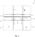
- Fig. 3 illustrates a section through an alternative embodiment of a construction 1 comprising a first element 2 and a second element 8.
- the first element 2 comprises a first duct 5, and the second element 8 comprises a second duct 11.
- the first and second elements 2, 8 are positioned horizontally to form e.g. a deck or a bridge.
- the first and second ducts 5, 11 protrude (not shown) from the first and second elements 2, 8.
- the first and second elements 2, 8 are arranged so that the second end 4 and the third end 9 are facing each other and so that the openings 7, 12 are aligned.
Landscapes
- Engineering & Computer Science (AREA)
- Architecture (AREA)
- Civil Engineering (AREA)
- Structural Engineering (AREA)
- General Engineering & Computer Science (AREA)
- Mechanical Engineering (AREA)
- Bridges Or Land Bridges (AREA)
- Closures For Containers (AREA)
Claims (15)
- Konstruktion, die Folgendes aufweist:- ein erstes Element, das sich zwischen einem ersten und einem zweiten gegenüberliegenden freien Ende erstreckt und einen ersten Kanal, der eine Öffnung in jedem des ersten und zweiten freien Endes bildet, aufweist;- ein zweites Element, das sich zwischen einem dritten und einem vierten gegenüberliegenden freien Ende erstreckt und einen zweiten Kanal, der eine Öffnung in jedem des dritten und vierten freien Ende bildet, aufweist;wobei das erste und zweite Element derart angeordnet sind, dass das zweite freie Ende und das dritte freie Ende einander zugewandt sind;
wobei der erste und zweite Kanal von dem ersten und zweiten Element vorstehen; und
wobei die Konstruktion ferner eine Rohrverbindung mit einem Körper aus einem flexiblen Material, um zu gestatten, dass sich der Körper verformt, um den Körper an einen ersten Kanal und einen zweiten Kanal, die nicht ausgerichtet sind, anpasst, aufweist, wobei die Rohrverbindung dazu ausgelegt ist, Kommunikation zwischen dem ersten und zweiten Kanal bereitzustellen und einen ununterbrochenen Kanal von dem ersten freien Ende zu dem vierten freien Ende bereitzustellen. - Konstruktion nach Anspruch 1, wobei die Verbindung ferner mindestens einen nichtflexiblen Übergangsteil aufweist, der an einem Ende des Körpers angebracht werden kann und eine Aufnahme bildet, die in einem der Kanäle aufgenommen wird.
- Konstruktion nach Anspruch 1 oder 2, wobei die Verbindung ferner eine Verriegelungsstruktur zum Verriegeln der Verbindung an mindestens einem der Kanäle aufweist.
- Konstruktion nach einem der vorhergehenden Ansprüche, die ferner eine längliche Verstärkungsstruktur aufweist, die sich durch die Verbindung und den ersten und zweiten Kanal erstreckt.
- Konstruktion nach einem der vorhergehenden Ansprüche, die ferner ein drittes Element aufweist, das sich zwischen einem fünften und einem sechsten gegenüberliegenden freien Ende erstreckt und einen dritten Kanal, der eine Öffnung in jedem des fünften und sechsten freien Endes bildet, aufweist, wobei das dritte Element derart angeordnet ist, dass das fünfte Ende dem vierten Ende zugewandt ist; und wobei eine zweite Rohrverbindung dazu angeordnet ist, Kommunikation zwischen dem dritten Kanal und einem des ersten und zweiten Kanals bereitzustellen, um dadurch einen ununterbrochenen Kanal von dem ersten Ende zu dem sechsten Ende bereitzustellen.
- Konstruktion nach Anspruch 5, wobei sich die Verstärkungsstruktur durch die Verbindungen und den ersten, zweiten und dritten Kanal erstreckt.
- Konstruktion nach einem der Ansprüche 4 bis 6, wobei die Verstärkungsstruktur mindestens ein Kabel aufweist.
- Konstruktion nach einem der Ansprüche 4 bis 7, wobei die Verstärkungsstruktur gespannt ist, um die Konstruktion zu stärken.
- Konstruktion nach einem der vorhergehenden Ansprüche, wobei der ununterbrochene Kanal mit einem Füllmaterial befüllt ist.
- Konstruktion nach einem der Ansprüche 4 bis 7, wobei sich mindestens ein Teil der länglichen Verstärkungsstruktur in einer länglichen Abschirmung befindet.
- Verfahren zum Herstellen einer Konstruktion, wobei das Verfahren die folgenden Schritte aufweist:- Bereitstellen eines ersten Elements, das sich zwischen einem ersten und einem zweiten gegenüberliegenden freien Ende erstreckt und einen ersten Kanal, der eine Öffnung in jedem des ersten und zweiten freien Endes bildet, aufweist, wobei der erste Kanal von dem ersten Element vorsteht;- Bereitstellen eines zweiten Elements, das sich zwischen einem dritten und einem vierten gegenüberliegenden freien Ende erstreckt und einen zweiten Kanal, der eine Öffnung in jedem des dritten und vierten freien Endes bildet, aufweist, wobei der zweite Kanal von dem zweiten Element vorsteht;- Anordnen des ersten und zweiten Elements derart, dass das zweite freie Ende und das dritte freie Ende einander zugewandt sind; und- Anordnen einer Rohrverbindung mit einem Körper aus einem flexiblen Material, das gestattet, dass sich der Körper verformt, zwischen dem ersten und zweiten Element, um Kommunikation zwischen dem ersten und zweiten Kanal bereitzustellen, und um einen ununterbrochenen Kanal von dem ersten freien Ende zu dem vierten Ende bereitzustellen, wobei das flexible Material gestattet, dass sich der Körper hinsichtlich eines ersten Kanals und eines zweiten Kanals, die nicht ausgerichtet sind, verformt.
- Verfahren nach Anspruch 11, das ferner einen Schritt des Anordnens einer Verstärkungsstruktur derart, dass sie sich durch die Verbindung und den ersten und zweiten Kanal von dem vierten Ende zu dem ersten Ende erstreckt, aufweist.
- Verfahren nach Anspruch 11 oder 12, das ferner einen Schritt des Befüllens des ununterbrochenen Kanals mit einem Füllmaterial aufweist.
- Verfahren nach Anspruch 13, wobei das Füllmaterial durch einen Einlass eingespritzt wird und von dem Einlass vertikal nach oben zu einem oberen Ende des Kanals fließt.
- Verfahren nach Anspruch 13, wobei das Füllmaterial durch einen Einlass eingespritzt wird und von dem Einlass horizontal zu einem gegenüberliegenden Ende des Kanals fließt.
Priority Applications (1)
| Application Number | Priority Date | Filing Date | Title |
|---|---|---|---|
| EP18195022.1A EP3460140A1 (de) | 2013-12-20 | 2014-12-19 | Konstruktion und verfahren zur herstellung einer konstruktion |
Applications Claiming Priority (2)
| Application Number | Priority Date | Filing Date | Title |
|---|---|---|---|
| DKPA201370814 | 2013-12-20 | ||
| PCT/EP2014/078666 WO2015091915A1 (en) | 2013-12-20 | 2014-12-19 | A construction and a method of making a construction |
Related Child Applications (2)
| Application Number | Title | Priority Date | Filing Date |
|---|---|---|---|
| EP18195022.1A Division-Into EP3460140A1 (de) | 2013-12-20 | 2014-12-19 | Konstruktion und verfahren zur herstellung einer konstruktion |
| EP18195022.1A Division EP3460140A1 (de) | 2013-12-20 | 2014-12-19 | Konstruktion und verfahren zur herstellung einer konstruktion |
Publications (3)
| Publication Number | Publication Date |
|---|---|
| EP3084097A1 EP3084097A1 (de) | 2016-10-26 |
| EP3084097B1 true EP3084097B1 (de) | 2018-09-19 |
| EP3084097B8 EP3084097B8 (de) | 2019-03-20 |
Family
ID=52144699
Family Applications (2)
| Application Number | Title | Priority Date | Filing Date |
|---|---|---|---|
| EP18195022.1A Withdrawn EP3460140A1 (de) | 2013-12-20 | 2014-12-19 | Konstruktion und verfahren zur herstellung einer konstruktion |
| EP14816247.2A Not-in-force EP3084097B8 (de) | 2013-12-20 | 2014-12-19 | Konstruktion und verfahren zur herstellung einer konstruktion |
Family Applications Before (1)
| Application Number | Title | Priority Date | Filing Date |
|---|---|---|---|
| EP18195022.1A Withdrawn EP3460140A1 (de) | 2013-12-20 | 2014-12-19 | Konstruktion und verfahren zur herstellung einer konstruktion |
Country Status (4)
| Country | Link |
|---|---|
| US (1) | US9856648B2 (de) |
| EP (2) | EP3460140A1 (de) |
| DK (1) | DK3084097T3 (de) |
| WO (1) | WO2015091915A1 (de) |
Families Citing this family (1)
| Publication number | Priority date | Publication date | Assignee | Title |
|---|---|---|---|---|
| DK3084097T3 (en) | 2013-12-20 | 2018-10-08 | Ccl Int Ltd | Design and method of manufacturing a structure |
Citations (14)
| Publication number | Priority date | Publication date | Assignee | Title |
|---|---|---|---|---|
| US3774944A (en) | 1971-10-15 | 1973-11-27 | Utility Precasters Inc | Conduit joint construction |
| CN85201993U (zh) | 1985-05-23 | 1986-03-12 | 周天生 | 一种家庭厨房用硬质塑料洗涤槽 |
| FR2596439A1 (fr) | 1986-03-26 | 1987-10-02 | Techniport Sa | Dispositif de liaison pour gaine de beton precontraint |
| DE8701271U1 (de) | 1987-01-27 | 1988-05-26 | Klöber, Johannes, 5828 Ennepetal | Verbindungsschlauch |
| EP0348870A1 (de) | 1988-06-27 | 1990-01-03 | Werner Zapf | Aus mehreren Stahlbetonfertigteilen zusammengefügter Baukörper in einer Spannbetonbauweise |
| JPH03115609A (ja) | 1989-03-27 | 1991-05-16 | De-P Kensetsu Kogyo Kk | 間詰シースおよびこの間詰シースの橋桁への取り付け方法 |
| JPH0946836A (ja) | 1995-07-25 | 1997-02-14 | Taisei Corp | 電線管の配管工法 |
| US5775849A (en) | 1996-04-25 | 1998-07-07 | Sorkin; Felix L. | Coupler for ducts used in post-tension rock anchorage systems |
| JPH10252222A (ja) | 1997-03-11 | 1998-09-22 | Kurosawa Kensetsu Kk | 接続管およびシースおよびプレキャスト部材の接続方法 |
| JP2002030610A (ja) | 2000-05-12 | 2002-01-31 | Totaku Kogyo Kk | Pc橋用プレキャストセグメントの接合方法とそれに使用するセグメント及びシースの端部部材 |
| CN1451824A (zh) | 2002-04-08 | 2003-10-29 | 东拓工业株式会社 | 套管用接头以及使用该接头的套管的连接结构 |
| US6874821B1 (en) | 2002-05-07 | 2005-04-05 | Felix L. Sorkin | Coupler apparatus for use with angled post-tension cables in precast concrete segmental construction |
| WO2007145477A1 (en) | 2006-06-15 | 2007-12-21 | Daewoo Engineering & Construction Co., Ltd | Precast concrete segment having connecting structure using steel duct, and connecting structure thereof |
| WO2015091915A1 (en) | 2013-12-20 | 2015-06-25 | A/S Skandinavisk Spændbeton | A construction and a method of making a construction |
Family Cites Families (19)
| Publication number | Priority date | Publication date | Assignee | Title |
|---|---|---|---|---|
| US1881913A (en) * | 1928-03-09 | 1932-10-11 | Brown Co | Method of laying multiple conduit and coupling for same |
| US3370870A (en) * | 1966-08-15 | 1968-02-27 | Gamah Corp | Flexible tubular coupling |
| US3574356A (en) * | 1969-03-19 | 1971-04-13 | Phillip Salerno | Preformed conduit |
| AU5379269A (en) * | 1969-04-21 | 1970-10-29 | John Laing And Son Limited | Duct former |
| US3606395A (en) * | 1969-08-04 | 1971-09-20 | Raffa Angelo | Method and apparatus using preformed conduits |
| US3711127A (en) * | 1971-07-08 | 1973-01-16 | A Raffa | Duct bank with coupling |
| US3820572A (en) * | 1972-01-20 | 1974-06-28 | Price Brothers Co | Pipe structure |
| US3873134A (en) * | 1973-01-04 | 1975-03-25 | Michael Sammaritano | Apparatus for joining preformed conduits |
| DE4106378A1 (de) * | 1991-02-28 | 1992-09-10 | Hewing Gmbh | Anschlussvorrichtung fuer kunststoffrohre und verfahren zum anschliessen eines kunststoffrohres |
| ES2083721T3 (es) * | 1991-07-04 | 1996-04-16 | Vsl Int Ag | Dispositivo para la union de dos tubos de envuelta. |
| JPH07166650A (ja) * | 1993-12-14 | 1995-06-27 | Puresutoresuto Concrete Kensetsugiyou Kyokai | 目地部ジョイントシース |
| US5421623A (en) * | 1994-05-26 | 1995-06-06 | Cassin; Allen E. | Friction sealed coupling for pipe |
| JPH09196269A (ja) * | 1996-01-19 | 1997-07-29 | Smc Corp | 管継手 |
| DE19935246B4 (de) * | 1999-06-04 | 2004-07-22 | Friatec Ag | Steckverbinder |
| US6241291B1 (en) * | 2000-06-09 | 2001-06-05 | Chao Hui-Chen | Pipe connector |
| US7267375B1 (en) * | 2004-10-25 | 2007-09-11 | Sorkin Felix L | Duct coupler apparatus |
| EP1861562B1 (de) * | 2005-03-23 | 2010-10-27 | VSL International AG | Vorrichtung zur verbindung von hüllen |
| US7695021B1 (en) * | 2007-09-25 | 2010-04-13 | Sorkin Felix L | Gasketed coupler apparatus for use with concrete segments |
| FR2970724B1 (fr) * | 2008-10-06 | 2014-01-03 | Freyssinet | Raccordement de troncons de gaine de precontrainte d'un ouvrage ayant une serie d'elements prefabriques. |
-
2014
- 2014-12-19 DK DK14816247.2T patent/DK3084097T3/en active
- 2014-12-19 US US15/105,886 patent/US9856648B2/en not_active Expired - Fee Related
- 2014-12-19 WO PCT/EP2014/078666 patent/WO2015091915A1/en not_active Ceased
- 2014-12-19 EP EP18195022.1A patent/EP3460140A1/de not_active Withdrawn
- 2014-12-19 EP EP14816247.2A patent/EP3084097B8/de not_active Not-in-force
Patent Citations (14)
| Publication number | Priority date | Publication date | Assignee | Title |
|---|---|---|---|---|
| US3774944A (en) | 1971-10-15 | 1973-11-27 | Utility Precasters Inc | Conduit joint construction |
| CN85201993U (zh) | 1985-05-23 | 1986-03-12 | 周天生 | 一种家庭厨房用硬质塑料洗涤槽 |
| FR2596439A1 (fr) | 1986-03-26 | 1987-10-02 | Techniport Sa | Dispositif de liaison pour gaine de beton precontraint |
| DE8701271U1 (de) | 1987-01-27 | 1988-05-26 | Klöber, Johannes, 5828 Ennepetal | Verbindungsschlauch |
| EP0348870A1 (de) | 1988-06-27 | 1990-01-03 | Werner Zapf | Aus mehreren Stahlbetonfertigteilen zusammengefügter Baukörper in einer Spannbetonbauweise |
| JPH03115609A (ja) | 1989-03-27 | 1991-05-16 | De-P Kensetsu Kogyo Kk | 間詰シースおよびこの間詰シースの橋桁への取り付け方法 |
| JPH0946836A (ja) | 1995-07-25 | 1997-02-14 | Taisei Corp | 電線管の配管工法 |
| US5775849A (en) | 1996-04-25 | 1998-07-07 | Sorkin; Felix L. | Coupler for ducts used in post-tension rock anchorage systems |
| JPH10252222A (ja) | 1997-03-11 | 1998-09-22 | Kurosawa Kensetsu Kk | 接続管およびシースおよびプレキャスト部材の接続方法 |
| JP2002030610A (ja) | 2000-05-12 | 2002-01-31 | Totaku Kogyo Kk | Pc橋用プレキャストセグメントの接合方法とそれに使用するセグメント及びシースの端部部材 |
| CN1451824A (zh) | 2002-04-08 | 2003-10-29 | 东拓工业株式会社 | 套管用接头以及使用该接头的套管的连接结构 |
| US6874821B1 (en) | 2002-05-07 | 2005-04-05 | Felix L. Sorkin | Coupler apparatus for use with angled post-tension cables in precast concrete segmental construction |
| WO2007145477A1 (en) | 2006-06-15 | 2007-12-21 | Daewoo Engineering & Construction Co., Ltd | Precast concrete segment having connecting structure using steel duct, and connecting structure thereof |
| WO2015091915A1 (en) | 2013-12-20 | 2015-06-25 | A/S Skandinavisk Spændbeton | A construction and a method of making a construction |
Non-Patent Citations (3)
| Title |
|---|
| ANONYMOUS: "VSL Strand Post-Tensioning Systems", VSL INTERNATIONAL, January 2015 (2015-01-01), XP055615978, Retrieved from the Internet <URL:www.vsl.com › download › getfile=vsl-strand-post-tensioning-systems> |
| CORVEN ENGINEERING: "New Directions for Florida Post-Tensioned Bridges , Volume 3 of 10: Design and construction Inspection of Precast Segmental Span-By-Span-Bridges", FLORIDA DEPARTMENT OF TRANSPORTATION (FDT), 1 September 2002 (2002-09-01), pages 1 - 44, XP055615973 |
| U.S DEPARTMENT OF TRANSPORTATION ET AL.: "Connection Details for Prefabricated Bridge Elements and Systems", REPORT NO. FHWA-IF-09-010, 30 March 2009 (2009-03-30), XP055615985, Retrieved from the Internet <URL:https://www.fhwa.dot.gov/bridge/prefab/if09010/report.pdf> |
Also Published As
| Publication number | Publication date |
|---|---|
| EP3084097B8 (de) | 2019-03-20 |
| EP3460140A1 (de) | 2019-03-27 |
| US20160312469A1 (en) | 2016-10-27 |
| US9856648B2 (en) | 2018-01-02 |
| DK3084097T3 (en) | 2018-10-08 |
| WO2015091915A1 (en) | 2015-06-25 |
| EP3084097A1 (de) | 2016-10-26 |
Similar Documents
| Publication | Publication Date | Title |
|---|---|---|
| EP3450632B1 (de) | Vorgespannte rohrabschnittsstruktur und konstruktionsverfahren dafür | |
| EP3146248B1 (de) | Röhrenkupplung für nachgespanntes betonelement | |
| EP2550400B2 (de) | Dichtungsanordnung | |
| US9714495B2 (en) | Pre-stressed molded wall, and method for creating such a wall | |
| JP6427045B2 (ja) | 既設コンクリート構造物の補強構造及び補強方法 | |
| WO2001084037A1 (en) | Duct repairing material, repairing structure, and repairing method | |
| US20140367961A1 (en) | Duct coupler devices, systems, and related methods | |
| US7299516B2 (en) | Construction of a corrosion-resistant tension member in the area of a rerouting point arranged on a support, particularly an inclined cable on the pylon of a cable stayed bridge | |
| EP2550401B1 (de) | Sattelsteg und verfahren zum schutz der stränge von korrosion in diesem sattelsteg | |
| JPS61502697A (ja) | 埋設用大断面導管 | |
| CN107524163A (zh) | 一种钢帽密封锚具及预应力张拉施工方法 | |
| JP4431084B2 (ja) | 支持部に配設された転向個所の領域における腐食防止された牽引部材、特に斜張橋の橋脚における斜張ケーブルの構造 | |
| KR101606101B1 (ko) | 프리스트레스 공법을 이용한 강합성 중공 rc 해중 터널 및 그 시공방법 | |
| US9856648B2 (en) | Construction and a method of making a construction | |
| KR200452669Y1 (ko) | 조립식 프리캐스트 콘크리트 pc 암거의 조립구조 | |
| RU51639U1 (ru) | Узел соединения армирующих стержней центрально сжатых железобетонных элементов | |
| KR101283556B1 (ko) | 농수로용 신축이음장치 및 이의 시공방법 | |
| KR101238640B1 (ko) | 지압전단띠에 의한 증진된 전단결합의 접합부를 가지는 기둥 | |
| KR100825833B1 (ko) | 관 연결 구조 | |
| JP3711414B1 (ja) | 可撓管 | |
| KR100720730B1 (ko) | 고강도 콘크리트를 충전한 이중 합성튜브 구조체 및 이를연결하는 접합방법 | |
| JP7767106B2 (ja) | 内面部材連結材、これを備えた管路の内張り構造、及び管路の内張り方法 | |
| JP6209014B2 (ja) | コンクリート部材の接合方法 | |
| KR20100127060A (ko) | 강합성 교량 및 이를 가설하기 위한 하이브리드 주탑 | |
| EP1070857A2 (de) | Kantenverbindung |
Legal Events
| Date | Code | Title | Description |
|---|---|---|---|
| PUAI | Public reference made under article 153(3) epc to a published international application that has entered the european phase |
Free format text: ORIGINAL CODE: 0009012 |
|
| 17P | Request for examination filed |
Effective date: 20160720 |
|
| AK | Designated contracting states |
Kind code of ref document: A1 Designated state(s): AL AT BE BG CH CY CZ DE DK EE ES FI FR GB GR HR HU IE IS IT LI LT LU LV MC MK MT NL NO PL PT RO RS SE SI SK SM TR |
|
| AX | Request for extension of the european patent |
Extension state: BA ME |
|
| DAX | Request for extension of the european patent (deleted) | ||
| GRAP | Despatch of communication of intention to grant a patent |
Free format text: ORIGINAL CODE: EPIDOSNIGR1 |
|
| STAA | Information on the status of an ep patent application or granted ep patent |
Free format text: STATUS: GRANT OF PATENT IS INTENDED |
|
| RIC1 | Information provided on ipc code assigned before grant |
Ipc: E04C 5/10 20060101AFI20170901BHEP Ipc: E04C 5/08 20060101ALI20170901BHEP |
|
| INTG | Intention to grant announced |
Effective date: 20171004 |
|
| GRAJ | Information related to disapproval of communication of intention to grant by the applicant or resumption of examination proceedings by the epo deleted |
Free format text: ORIGINAL CODE: EPIDOSDIGR1 |
|
| STAA | Information on the status of an ep patent application or granted ep patent |
Free format text: STATUS: REQUEST FOR EXAMINATION WAS MADE |
|
| INTC | Intention to grant announced (deleted) | ||
| GRAP | Despatch of communication of intention to grant a patent |
Free format text: ORIGINAL CODE: EPIDOSNIGR1 |
|
| STAA | Information on the status of an ep patent application or granted ep patent |
Free format text: STATUS: GRANT OF PATENT IS INTENDED |
|
| INTG | Intention to grant announced |
Effective date: 20180403 |
|
| RIC1 | Information provided on ipc code assigned before grant |
Ipc: E04C 5/08 20060101ALI20180319BHEP Ipc: E04C 5/10 20060101AFI20180319BHEP Ipc: E04C 5/16 20060101ALN20180319BHEP Ipc: F16L 9/08 20060101ALN20180319BHEP |
|
| GRAS | Grant fee paid |
Free format text: ORIGINAL CODE: EPIDOSNIGR3 |
|
| GRAA | (expected) grant |
Free format text: ORIGINAL CODE: 0009210 |
|
| STAA | Information on the status of an ep patent application or granted ep patent |
Free format text: STATUS: THE PATENT HAS BEEN GRANTED |
|
| AK | Designated contracting states |
Kind code of ref document: B1 Designated state(s): AL AT BE BG CH CY CZ DE DK EE ES FI FR GB GR HR HU IE IS IT LI LT LU LV MC MK MT NL NO PL PT RO RS SE SI SK SM TR |
|
| REG | Reference to a national code |
Ref country code: GB Ref legal event code: FG4D |
|
| REG | Reference to a national code |
Ref country code: CH Ref legal event code: EP |
|
| REG | Reference to a national code |
Ref country code: DK Ref legal event code: T3 Effective date: 20181001 |
|
| REG | Reference to a national code |
Ref country code: AT Ref legal event code: REF Ref document number: 1043433 Country of ref document: AT Kind code of ref document: T Effective date: 20181015 |
|
| REG | Reference to a national code |
Ref country code: IE Ref legal event code: FG4D |
|
| REG | Reference to a national code |
Ref country code: DE Ref legal event code: R096 Ref document number: 602014032657 Country of ref document: DE |
|
| REG | Reference to a national code |
Ref country code: NL Ref legal event code: FP |
|
| GRAT | Correction requested after decision to grant or after decision to maintain patent in amended form |
Free format text: ORIGINAL CODE: EPIDOSNCDEC |
|
| PG25 | Lapsed in a contracting state [announced via postgrant information from national office to epo] |
Ref country code: RS Free format text: LAPSE BECAUSE OF FAILURE TO SUBMIT A TRANSLATION OF THE DESCRIPTION OR TO PAY THE FEE WITHIN THE PRESCRIBED TIME-LIMIT Effective date: 20180919 Ref country code: SE Free format text: LAPSE BECAUSE OF FAILURE TO SUBMIT A TRANSLATION OF THE DESCRIPTION OR TO PAY THE FEE WITHIN THE PRESCRIBED TIME-LIMIT Effective date: 20180919 Ref country code: GR Free format text: LAPSE BECAUSE OF FAILURE TO SUBMIT A TRANSLATION OF THE DESCRIPTION OR TO PAY THE FEE WITHIN THE PRESCRIBED TIME-LIMIT Effective date: 20181220 Ref country code: LT Free format text: LAPSE BECAUSE OF FAILURE TO SUBMIT A TRANSLATION OF THE DESCRIPTION OR TO PAY THE FEE WITHIN THE PRESCRIBED TIME-LIMIT Effective date: 20180919 Ref country code: BG Free format text: LAPSE BECAUSE OF FAILURE TO SUBMIT A TRANSLATION OF THE DESCRIPTION OR TO PAY THE FEE WITHIN THE PRESCRIBED TIME-LIMIT Effective date: 20181219 |
|
| PGFP | Annual fee paid to national office [announced via postgrant information from national office to epo] |
Ref country code: CZ Payment date: 20190416 Year of fee payment: 5 Ref country code: IE Payment date: 20181219 Year of fee payment: 5 Ref country code: DE Payment date: 20181220 Year of fee payment: 5 |
|
| REG | Reference to a national code |
Ref country code: SE Ref legal event code: TRGR |
|
| REG | Reference to a national code |
Ref country code: LT Ref legal event code: MG4D |
|
| RAP2 | Party data changed (patent owner data changed or rights of a patent transferred) |
Owner name: CCL STRESSING INTERNATIONAL LIMITED |
|
| REG | Reference to a national code |
Ref country code: NO Ref legal event code: T2 Effective date: 20180919 Ref country code: BE Ref legal event code: HC Owner name: CCL STRESSING INTERNATIONAL LIMITED; GB Free format text: DETAILS ASSIGNMENT: CHANGE OF OWNER(S), CHANGEMENT DE NOM DU PROPRIETAIRE, CORRECTION; FORMER OWNER NAME: CCL INTERNATIONAL LTD. Effective date: 20190123 |
|
| PG25 | Lapsed in a contracting state [announced via postgrant information from national office to epo] |
Ref country code: LV Free format text: LAPSE BECAUSE OF FAILURE TO SUBMIT A TRANSLATION OF THE DESCRIPTION OR TO PAY THE FEE WITHIN THE PRESCRIBED TIME-LIMIT Effective date: 20180919 Ref country code: AL Free format text: LAPSE BECAUSE OF FAILURE TO SUBMIT A TRANSLATION OF THE DESCRIPTION OR TO PAY THE FEE WITHIN THE PRESCRIBED TIME-LIMIT Effective date: 20180919 Ref country code: HR Free format text: LAPSE BECAUSE OF FAILURE TO SUBMIT A TRANSLATION OF THE DESCRIPTION OR TO PAY THE FEE WITHIN THE PRESCRIBED TIME-LIMIT Effective date: 20180919 |
|
| PGFP | Annual fee paid to national office [announced via postgrant information from national office to epo] |
Ref country code: FR Payment date: 20181214 Year of fee payment: 5 Ref country code: BE Payment date: 20181220 Year of fee payment: 5 |
|
| REG | Reference to a national code |
Ref country code: CH Ref legal event code: PK Free format text: BERICHTIGUNG B8 |
|
| REG | Reference to a national code |
Ref country code: AT Ref legal event code: MK05 Ref document number: 1043433 Country of ref document: AT Kind code of ref document: T Effective date: 20180919 |
|
| PG25 | Lapsed in a contracting state [announced via postgrant information from national office to epo] |
Ref country code: IT Free format text: LAPSE BECAUSE OF FAILURE TO SUBMIT A TRANSLATION OF THE DESCRIPTION OR TO PAY THE FEE WITHIN THE PRESCRIBED TIME-LIMIT Effective date: 20180919 Ref country code: PL Free format text: LAPSE BECAUSE OF FAILURE TO SUBMIT A TRANSLATION OF THE DESCRIPTION OR TO PAY THE FEE WITHIN THE PRESCRIBED TIME-LIMIT Effective date: 20180919 Ref country code: EE Free format text: LAPSE BECAUSE OF FAILURE TO SUBMIT A TRANSLATION OF THE DESCRIPTION OR TO PAY THE FEE WITHIN THE PRESCRIBED TIME-LIMIT Effective date: 20180919 Ref country code: CZ Free format text: LAPSE BECAUSE OF FAILURE TO SUBMIT A TRANSLATION OF THE DESCRIPTION OR TO PAY THE FEE WITHIN THE PRESCRIBED TIME-LIMIT Effective date: 20180919 Ref country code: RO Free format text: LAPSE BECAUSE OF FAILURE TO SUBMIT A TRANSLATION OF THE DESCRIPTION OR TO PAY THE FEE WITHIN THE PRESCRIBED TIME-LIMIT Effective date: 20180919 Ref country code: ES Free format text: LAPSE BECAUSE OF FAILURE TO SUBMIT A TRANSLATION OF THE DESCRIPTION OR TO PAY THE FEE WITHIN THE PRESCRIBED TIME-LIMIT Effective date: 20180919 Ref country code: AT Free format text: LAPSE BECAUSE OF FAILURE TO SUBMIT A TRANSLATION OF THE DESCRIPTION OR TO PAY THE FEE WITHIN THE PRESCRIBED TIME-LIMIT Effective date: 20180919 Ref country code: IS Free format text: LAPSE BECAUSE OF FAILURE TO SUBMIT A TRANSLATION OF THE DESCRIPTION OR TO PAY THE FEE WITHIN THE PRESCRIBED TIME-LIMIT Effective date: 20190119 |
|
| PG25 | Lapsed in a contracting state [announced via postgrant information from national office to epo] |
Ref country code: SK Free format text: LAPSE BECAUSE OF FAILURE TO SUBMIT A TRANSLATION OF THE DESCRIPTION OR TO PAY THE FEE WITHIN THE PRESCRIBED TIME-LIMIT Effective date: 20180919 Ref country code: PT Free format text: LAPSE BECAUSE OF FAILURE TO SUBMIT A TRANSLATION OF THE DESCRIPTION OR TO PAY THE FEE WITHIN THE PRESCRIBED TIME-LIMIT Effective date: 20190119 Ref country code: SM Free format text: LAPSE BECAUSE OF FAILURE TO SUBMIT A TRANSLATION OF THE DESCRIPTION OR TO PAY THE FEE WITHIN THE PRESCRIBED TIME-LIMIT Effective date: 20180919 |
|
| REG | Reference to a national code |
Ref country code: DE Ref legal event code: R026 Ref document number: 602014032657 Country of ref document: DE |
|
| REG | Reference to a national code |
Ref country code: NL Ref legal event code: HC Owner name: CCL STRESSING INTERNATIONAL LIMITED; GB Free format text: DETAILS ASSIGNMENT: CHANGE OF OWNER(S), CHANGE OF OWNER(S) NAME; FORMER OWNER NAME: CCL INTERNATIONAL LTD. Effective date: 20190517 |
|
| PLBI | Opposition filed |
Free format text: ORIGINAL CODE: 0009260 |
|
| PLAX | Notice of opposition and request to file observation + time limit sent |
Free format text: ORIGINAL CODE: EPIDOSNOBS2 |
|
| 26 | Opposition filed |
Opponent name: NCC DANMARK A/S Effective date: 20190618 |
|
| REG | Reference to a national code |
Ref country code: CH Ref legal event code: PL |
|
| PG25 | Lapsed in a contracting state [announced via postgrant information from national office to epo] |
Ref country code: MC Free format text: LAPSE BECAUSE OF FAILURE TO SUBMIT A TRANSLATION OF THE DESCRIPTION OR TO PAY THE FEE WITHIN THE PRESCRIBED TIME-LIMIT Effective date: 20180919 Ref country code: LU Free format text: LAPSE BECAUSE OF NON-PAYMENT OF DUE FEES Effective date: 20181219 |
|
| PG25 | Lapsed in a contracting state [announced via postgrant information from national office to epo] |
Ref country code: SI Free format text: LAPSE BECAUSE OF FAILURE TO SUBMIT A TRANSLATION OF THE DESCRIPTION OR TO PAY THE FEE WITHIN THE PRESCRIBED TIME-LIMIT Effective date: 20180919 |
|
| PLBB | Reply of patent proprietor to notice(s) of opposition received |
Free format text: ORIGINAL CODE: EPIDOSNOBS3 |
|
| PG25 | Lapsed in a contracting state [announced via postgrant information from national office to epo] |
Ref country code: CH Free format text: LAPSE BECAUSE OF NON-PAYMENT OF DUE FEES Effective date: 20181231 Ref country code: LI Free format text: LAPSE BECAUSE OF NON-PAYMENT OF DUE FEES Effective date: 20181231 |
|
| PLBP | Opposition withdrawn |
Free format text: ORIGINAL CODE: 0009264 |
|
| PG25 | Lapsed in a contracting state [announced via postgrant information from national office to epo] |
Ref country code: MT Free format text: LAPSE BECAUSE OF NON-PAYMENT OF DUE FEES Effective date: 20181219 |
|
| PLBD | Termination of opposition procedure: decision despatched |
Free format text: ORIGINAL CODE: EPIDOSNOPC1 |
|
| REG | Reference to a national code |
Ref country code: DE Ref legal event code: R100 Ref document number: 602014032657 Country of ref document: DE |
|
| PG25 | Lapsed in a contracting state [announced via postgrant information from national office to epo] |
Ref country code: TR Free format text: LAPSE BECAUSE OF FAILURE TO SUBMIT A TRANSLATION OF THE DESCRIPTION OR TO PAY THE FEE WITHIN THE PRESCRIBED TIME-LIMIT Effective date: 20180919 |
|
| PG25 | Lapsed in a contracting state [announced via postgrant information from national office to epo] |
Ref country code: CY Free format text: LAPSE BECAUSE OF FAILURE TO SUBMIT A TRANSLATION OF THE DESCRIPTION OR TO PAY THE FEE WITHIN THE PRESCRIBED TIME-LIMIT Effective date: 20180919 Ref country code: HU Free format text: LAPSE BECAUSE OF FAILURE TO SUBMIT A TRANSLATION OF THE DESCRIPTION OR TO PAY THE FEE WITHIN THE PRESCRIBED TIME-LIMIT; INVALID AB INITIO Effective date: 20141219 Ref country code: MK Free format text: LAPSE BECAUSE OF NON-PAYMENT OF DUE FEES Effective date: 20180919 |
|
| REG | Reference to a national code |
Ref country code: DE Ref legal event code: R119 Ref document number: 602014032657 Country of ref document: DE |
|
| PLBM | Termination of opposition procedure: date of legal effect published |
Free format text: ORIGINAL CODE: 0009276 |
|
| REG | Reference to a national code |
Ref country code: FI Ref legal event code: MAE |
|
| PG25 | Lapsed in a contracting state [announced via postgrant information from national office to epo] |
Ref country code: FI Free format text: LAPSE BECAUSE OF NON-PAYMENT OF DUE FEES Effective date: 20191219 |
|
| REG | Reference to a national code |
Ref country code: NL Ref legal event code: MM Effective date: 20200101 |
|
| 27C | Opposition proceedings terminated |
Effective date: 20200314 |
|
| REG | Reference to a national code |
Ref country code: BE Ref legal event code: MM Effective date: 20191231 |
|
| PG25 | Lapsed in a contracting state [announced via postgrant information from national office to epo] |
Ref country code: NL Free format text: LAPSE BECAUSE OF NON-PAYMENT OF DUE FEES Effective date: 20200101 |
|
| PG25 | Lapsed in a contracting state [announced via postgrant information from national office to epo] |
Ref country code: IE Free format text: LAPSE BECAUSE OF NON-PAYMENT OF DUE FEES Effective date: 20191219 Ref country code: DE Free format text: LAPSE BECAUSE OF NON-PAYMENT OF DUE FEES Effective date: 20200701 Ref country code: FR Free format text: LAPSE BECAUSE OF NON-PAYMENT OF DUE FEES Effective date: 20191231 |
|
| PG25 | Lapsed in a contracting state [announced via postgrant information from national office to epo] |
Ref country code: BE Free format text: LAPSE BECAUSE OF NON-PAYMENT OF DUE FEES Effective date: 20191231 |
|
| P01 | Opt-out of the competence of the unified patent court (upc) registered |
Effective date: 20230515 |
|
| PGFP | Annual fee paid to national office [announced via postgrant information from national office to epo] |
Ref country code: GB Payment date: 20231215 Year of fee payment: 10 |
|
| PGFP | Annual fee paid to national office [announced via postgrant information from national office to epo] |
Ref country code: SE Payment date: 20231218 Year of fee payment: 10 Ref country code: NO Payment date: 20231218 Year of fee payment: 10 Ref country code: DK Payment date: 20231206 Year of fee payment: 10 |
|
| REG | Reference to a national code |
Ref country code: DK Ref legal event code: EBP Effective date: 20241231 |
|
| REG | Reference to a national code |
Ref country code: SE Ref legal event code: EUG |
|
| GBPC | Gb: european patent ceased through non-payment of renewal fee |
Effective date: 20241219 |
|
| PG25 | Lapsed in a contracting state [announced via postgrant information from national office to epo] |
Ref country code: NO Free format text: LAPSE BECAUSE OF NON-PAYMENT OF DUE FEES Effective date: 20241231 |
|
| PG25 | Lapsed in a contracting state [announced via postgrant information from national office to epo] |
Ref country code: GB Free format text: LAPSE BECAUSE OF NON-PAYMENT OF DUE FEES Effective date: 20241219 |
|
| PG25 | Lapsed in a contracting state [announced via postgrant information from national office to epo] |
Ref country code: DK Free format text: LAPSE BECAUSE OF NON-PAYMENT OF DUE FEES Effective date: 20241231 |