EP3084171B1 - Organe d'accouplement pour embiellage à plusieurs articulations et embiellage à plusieurs articulations - Google Patents
Organe d'accouplement pour embiellage à plusieurs articulations et embiellage à plusieurs articulations Download PDFInfo
- Publication number
- EP3084171B1 EP3084171B1 EP14843231.3A EP14843231A EP3084171B1 EP 3084171 B1 EP3084171 B1 EP 3084171B1 EP 14843231 A EP14843231 A EP 14843231A EP 3084171 B1 EP3084171 B1 EP 3084171B1
- Authority
- EP
- European Patent Office
- Prior art keywords
- eye
- coupling
- coupling element
- plane
- bolts
- Prior art date
- Legal status (The legal status is an assumption and is not a legal conclusion. Google has not performed a legal analysis and makes no representation as to the accuracy of the status listed.)
- Not-in-force
Links
Images


Classifications
-
- F—MECHANICAL ENGINEERING; LIGHTING; HEATING; WEAPONS; BLASTING
- F16—ENGINEERING ELEMENTS AND UNITS; GENERAL MEASURES FOR PRODUCING AND MAINTAINING EFFECTIVE FUNCTIONING OF MACHINES OR INSTALLATIONS; THERMAL INSULATION IN GENERAL
- F16C—SHAFTS; FLEXIBLE SHAFTS; ELEMENTS OR CRANKSHAFT MECHANISMS; ROTARY BODIES OTHER THAN GEARING ELEMENTS; BEARINGS
- F16C7/00—Connecting-rods or like links pivoted at both ends; Construction of connecting-rod heads
- F16C7/02—Constructions of connecting-rods with constant length
- F16C7/023—Constructions of connecting-rods with constant length for piston engines, pumps or the like
-
- F—MECHANICAL ENGINEERING; LIGHTING; HEATING; WEAPONS; BLASTING
- F02—COMBUSTION ENGINES; HOT-GAS OR COMBUSTION-PRODUCT ENGINE PLANTS
- F02B—INTERNAL-COMBUSTION PISTON ENGINES; COMBUSTION ENGINES IN GENERAL
- F02B75/00—Other engines
- F02B75/04—Engines with variable distances between pistons at top dead-centre positions and cylinder heads
- F02B75/045—Engines with variable distances between pistons at top dead-centre positions and cylinder heads by means of a variable connecting rod length
-
- F—MECHANICAL ENGINEERING; LIGHTING; HEATING; WEAPONS; BLASTING
- F02—COMBUSTION ENGINES; HOT-GAS OR COMBUSTION-PRODUCT ENGINE PLANTS
- F02B—INTERNAL-COMBUSTION PISTON ENGINES; COMBUSTION ENGINES IN GENERAL
- F02B75/00—Other engines
- F02B75/16—Engines characterised by number of cylinders, e.g. single-cylinder engines
-
- F—MECHANICAL ENGINEERING; LIGHTING; HEATING; WEAPONS; BLASTING
- F02—COMBUSTION ENGINES; HOT-GAS OR COMBUSTION-PRODUCT ENGINE PLANTS
- F02B—INTERNAL-COMBUSTION PISTON ENGINES; COMBUSTION ENGINES IN GENERAL
- F02B75/00—Other engines
- F02B75/32—Engines characterised by connections between pistons and main shafts and not specific to preceding main groups
Definitions
- the invention relates to a coupling member for a multi-joint crank drive of an internal combustion engine, comprising a coupling member comprising a coupling lever and a bearing cap, wherein the coupling lever a first eye for a piston connecting rod of the crank mechanism, a second eye for a Anlenkpleuel the crank mechanism and a third together with the bearing cap Eye for a crank pin of a crankshaft surrounds, wherein the coupling lever and the bearing cap on the outer circumference of the third eye in a passing through the center of the third eye separation plane abut each other and are screwed together by two screws, and wherein the two screws have parallel longitudinal central axes.
- the invention further relates to a multi-joint crank drive of an internal combustion engine having a plurality of such coupling members.
- Coupling members of the type mentioned are used in multi-joint crank drives of internal combustion engines as connecting links between the Kolbenpleueln associated with the piston, the associated crank pin of the crankshaft and associated, connected to an eccentric Anlenkpleueln.
- the working stroke of the pistons of the internal combustion engine can be adjusted so that different working strokes of the piston result in different operating strokes of the internal combustion engine.
- the working stroke is to be understood as meaning the distance which lies between an upper and a lower dead center of the piston, that is to say the maximum distance traveled by the piston during the working cycle.
- the compression ratio can be adjusted, which is achieved in the cylinder associated with the piston, in particular in dependence on the operating point of the internal combustion engine and / or the working stroke of the cylinder.
- the known coupling member has a split third eye and consists of a coupling lever and a bearing cover connected by two screws with the coupling lever, each forming one half of the third eye.
- the coupling lever and the bearing cap abut each other along the outer periphery of the third eye along two lines of contact, one through the center of the divided span the third eye extending dividing plane.
- the coupling lever and the bearing cap are connected by two screws whose longitudinal center axes are not aligned parallel to each other but "skewed".
- the present invention seeks to improve a coupling member and a multi-joint crank mechanism of the type mentioned in that can achieve a high strength without "skewed" screws between the coupling lever and the bearing cap with low mass of the coupling member.
- the parting plane is inclined at an acute angle with respect to a plane passing through the center of the eye and perpendicular to the longitudinal central axes of the two screws, wherein on the outer circumference of the third eye directly adjacent pairs of opposing contact surfaces of the coupling lever and the bearing cap on both sides of the third eye to the longitudinal center axes of the two screws are perpendicular. This means at the same time that the longitudinal center axes of both screws are not perpendicular to the parting plane.
- the distance between the first eye and the third eye can be kept very small, which contributes to a reduction in the mass of the coupling member.
- one of the first eye penetrated lifting arm of the coupling member are formed as a fork arm.
- the screw hole of the coupling lever on the side of the first eye can be conveniently formed as a through hole, which opens between two legs of the fork arm and receives one of the two screws.
- This screw on the side of the first eye is also referred to below as the first screw, while the screw on the side of the second eye is also referred to below as the second screw.
- the coupling lever and the bearing cap on both sides of the third eye immediately adjacent on the outer circumference opposite bearing surfaces, which are perpendicular to the longitudinal center axes of the two screws according to a further preferred embodiment of the invention.
- the two screws are advantageously sized differently, not only different in diameter but also have significantly different lengths.
- the first screw is advantageously thinner and advantageously also considerably shorter than the second screw. Both screws are expediently expansion screws, which can also absorb bending loads.
- the coupling lever and the bearing cap on both sides of the circumference of the third eye form-fitting against each other where they are each provided with complementary interlocking teeth.
- the toothing of the coupling lever and the bearing cap on the side of the first eye or around the first screw is hereinafter referred to as the first toothing, while the toothing on the side of the second eye or around the second screw is referred to as a second toothing.
- the two complementary teeth each extend along a dividing plane which is defined by the tips of the teeth of the toothing of the coupling lever. As with the coupling member from the DE 10 2011 116 609 A1 intersect the two graduation levels or include an angle not equal to 180 degrees.
- the division plane of the first toothing of the coupling lever is referred to below as the first division plane, while the dividing plane of the second toothing of the coupling lever is referred to below as the second dividing plane.
- the last tooth of the second toothing at the end facing away from the third eye end of the second toothing further moved away from an upper side of the coupling lever down and thereby in this area the height of the bending cross-section and thus the flexural strength of the coupling lever can be increased.
- a first angle between the dividing plane of the first toothing and the plane perpendicular to the longitudinal central axes of the two screws through the center of the third eye is smaller than a second angle between this plane and the dividing plane of the second toothing, the first angle being suitably about 15 degrees and the second angle is suitably about 20 degrees.
- a good compromise can be achieved between a sufficient height of the bending section on the side of the second eye on the one hand and a sufficient length of the screw hole on the side of the first eye on the other hand.
- the second dividing plane expediently has a lateral offset relative to the middle of the third eye and expediently runs through the first eye, advantageously approximately through its middle.
- the teeth of the first and second teeth tooth flanks with different angles of incidence with respect to the respective division plane in order to increase the contact surfaces along the two teeth and ensure the assembly.
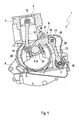
- internal combustion engine 1 is a series internal combustion engine, more precisely as a four-stroke four-cylinder in-line engine.
- the internal combustion engine 1 has a crankshaft 2 and four pistons 3 (only one shown), which are each movable in a cylinder 4 back and forth.
- the crankshaft 2 is rotatably mounted in shaft bearings (not shown) of a cylinder crankcase 5 and includes five serving for storage centric shaft journal (not visible) and four lifting or crank pin 6 (only one shown), the longitudinal center axes in different angular orientations parallel to the axis of rotation of the crankshaft 2 and are arranged in relation to this axis of rotation in different angular orientations.
- the internal combustion engine 1 further comprises an eccentric shaft 7 with a rotational axis parallel to the axis of rotation of the crankshaft 2, which is rotatably mounted next to and slightly below the crankshaft 2 in the cylinder crankcase 5, and a multi-joint crank mechanism 8 with four coupling members 9, each on one of the crank pin. 6 the crankshaft 2 are rotatably supported, wherein they are connected on one side of the crankshaft 2 by a Kolbenpleuel 10 with one of the pistons 3 and on the other side of the crankshaft 2 by a Anschpleuel 12 with the eccentric shaft 7.
- Each coupling member 9 comprises a shorter lifting arm 13, which is connected via a pivot joint 14 pivotally connected to a lower end of one of Kolbenpleuel 10. An upper end of the respective Kolbenpleuels 10 is articulated via a further pivot joint 15 on the associated piston 3. Overall, therefore, each of the four pistons 3 is connected by the respective Kolbenpleuel 10 and the respective coupling member 9 with the crankshaft 2.
- each coupling member 9 comprises a longer coupling arm 16, which is connected via a pivot joint 17 pivotally connected to an upper end of one of the Anlenkpleuel 12.
- a lower end of the respective Anlenkpleuels 12 is articulated via a further pivot joint 18 on the eccentric shaft 7.
- the Anschpleuel 12 are aligned approximately parallel to the Kolbenpleueln 10 and arranged in the axial direction of the crankshaft 2 and the eccentric shaft 7 in each case approximately in the same plane as the associated Kolbenpleuel 10.
- the compression ratio of the internal combustion engine 1 can be changed and the inclination of the piston connecting rods 10 with respect to the cylinder axis of the associated cylinders 4 can be reduced during the rotation of the crankshaft 2, resulting in a reduction of the piston side forces and thus the frictional forces between the piston 3 and cylinder walls of the cylinder 4.
- each coupling member 9 a first eye 19, a second eye 20 and a third eye 21 on.
- the first eye 19 extends through two fork legs 22 of the lifting arm 13 and, together with an associated bearing pin 23, the pivot joint 14 for the lower end of the Kolbenpleuels 10.
- the second eye 20 extends through two fork legs 24 of the coupling arm 16 and forms together with a
- the third eye 21 is disposed between the first and second eyes 19 and 20, has a larger diameter and serves to receive a crank pin 6.
- the third eye 21 is a split eye.
- the coupling member 9 consists of a coupling lever 26 and a bearing cap 27, which are connected by two screws 28, 29 on both sides of the eye 21 firmly together. How best in Fig. 4 shown, the two screws 28, 29 as well as the associated internal thread or screw holes 30, 31 in the coupling lever 12 and through holes (not visible) in the bearing cap 27 parallel longitudinal central axes 32, 33.
- the first screw 28 on the side of the first eye 19 is a short M9 screw, while the second screw 29 on the side of the second eye 20 is a longer M11 screw. Both screws 28, 29 are designed as expansion screws, so that they can withstand better bending loads.
- the coupling lever 26 and the bearing cap 27 each extend through 180 degrees around the outer circumference of the eye 21 and have on the outer circumference of the eye 21 two pairs of opposing planar contact surfaces 34, 35.
- the pairwise opposite abutment surfaces 34, 35 of the coupling lever 26 and of the bearing cap 27 on both sides directly adjoining the outer circumference of the third eye 21 of the third eye 21 to the longitudinal center axes 32, 33 of the two screws 28, 29 are perpendicular.
- the dividing plane T is inclined at an acute angle ⁇ of about 5 degrees with respect to a plane E perpendicular to the longitudinal center axes 32, 33 of the screws 28, 29 through the center 36 of the third eye 21.
- the longitudinal center axes 32, 33 of the screws 28, 29 are not aligned perpendicular to the parting plane T.
- the direction of the inclination of the parting plane T is selected so that it has on the side of the first eye 19 a greater distance than the plane E from the center of the first eye 19.
- the screw hole 30 can be formed as a through hole, which opens into the space between the two fork legs 22 of the lifting arm 13.
- the coupling lever 26 and the bearing cap 27 are on both sides of the eye 21 positively against each other.
- the coupling lever 26 is about the mouth of the screw hole 30 of the first screw 28 around with a first toothing 37 and around the mouth of the screw hole 31 of the second screw 29 around with a second toothing 38 provided.
- the first and second teeth 37, 38 each form-fitting with an opposite complementary first and second teeth 37, 38 of the bearing cap 27 in tooth engagement, as best in Fig. 3 shown.
- the two contact surfaces 34, 35 each form an adjacent to the eye 21 part of these teeth 37, 38th
- connection between the coupling lever 26 and the bearing cap 27 by two positive teeth 37, 38 allow the use of a high-strength and thus not crackable tempering steel, with which in comparison to a crackable version of the coupling member 9 also a mass reduction is possible.
- the tips of the teeth of the first toothing 37 of the coupling lever 26 a first division plane 39 and the tips of the teeth of the second toothing 38 of the coupling lever 26, a second graduation plane 40 on.
- the two graduation levels 39, 40 include different inclination angles ⁇ both with the separation plane T and with the plane E. While the inclination angle ⁇ 1 between the first dividing plane 39 and the plane E is 20 degrees, the inclination angle ⁇ 2 between the second dividing plane 40 and the plane E is smaller and is only 15 degrees. This allows the in Fig.
- the first graduation plane 39 extends through the center 36 of the third eye 21 or through the center axis of the crank pin 6 mounted in the third eye 21.
- the second graduation plane 40 or its extension extends approximately through the center of the first eye 19 and has a lateral offset relative to the center 36 of the third eye 21.
- the two graduation levels 39, 40 intersect within the third eye 21, but not in the middle between the two screws 28, 29, but closer to the second screw 29, wherein the distance of the Thomaspunks from the longitudinal central axis 32 of the first screw 28 the 3 to 4 times the distance from the longitudinal center axis 33 of the second screw 29 is.
Landscapes
- Engineering & Computer Science (AREA)
- General Engineering & Computer Science (AREA)
- Mechanical Engineering (AREA)
- Chemical & Material Sciences (AREA)
- Combustion & Propulsion (AREA)
- Shafts, Cranks, Connecting Bars, And Related Bearings (AREA)
- Sliding-Contact Bearings (AREA)
- Transmission Devices (AREA)
Claims (11)
- Organe d'accouplement (9) pour un embiellage à plusieurs articulations (8) d'un moteur à combustion interne (1), avec un levier d'accouplement (26) et un couvercle de palier (27), dans lequel le levier d'accouplement (26) entoure un premier oeillet (19) pour une bielle de piston (10) de l'embiellage (8), un deuxième oeillet (20) pour une bielle articulée (12) de l'embiellage (8) et conjointement avec le couvercle de palier (27), un troisième oeillet (21) pour un maneton (6) d'un vilebrequin (2), dans lequel le levier d'accouplement (26) et le couvercle de palier (27) butent l'un contre l'autre au niveau de la périphérie extérieure du troisième oeillet (21) dans un plan de séparation (T) s'étendant au travers du milieu (36) du troisième oeillet (21) et sont vissés par deux vis (28, 29) l'un à l'autre, caractérisé en ce que les deux vis (28, 29) présentent des axes médians longitudinaux (32, 33) parallèles, et que le plan de séparation (T) est incliné par rapport à un plan (E) s'étendant au travers du milieu de l'oeillet (36) et perpendiculaire aux axes médians longitudinaux (32, 33) des deux vis (28, 29) selon un angle aigu (α), dans lequel des surfaces d'appui (34, 35), opposées par paires directement contiguës à la périphérie extérieure du troisième oeillet (21), du levier d'accouplement (26) et du couvercle de palier (27) de part et d'autre du troisième oeillet (21) sont perpendiculaires aux axes médians longitudinaux (32, 33) des deux vis (28, 29).
- Organe d'accouplement selon la revendication 1, caractérisé en ce que le plan de séparation (T) est incliné sur le côté du premier oeillet (19) dans une direction loin du premier oeillet (19).
- Organe d'accouplement selon la revendication 1 ou 2, caractérisé en ce que l'axe médian longitudinal (32) de la première vis (28) agencée sur le côté du premier oeillet (19) s'étend au travers du premier oeillet (19, 21).
- Organe d'accouplement selon l'une des revendications précédentes, caractérisé en ce qu'un bras de levage (13), traversé par le premier oeillet (19), de l'organe d'accouplement (9) est réalisé comme bras de fourche avec deux branches de fourche (22).
- Organe d'accouplement selon les revendications 3 et 4, caractérisé en ce que le perçage de vis (30) est un perçage traversant débouchant entre les branches de fourche (22).
- Organe d'accouplement selon l'une des revendications précédentes, caractérisé en ce que les vis (28, 29) sont des vis à tige allégée.
- Organe d'accouplement selon l'une des revendications précédentes, caractérisé en ce que le levier d'accouplement (26) et le couvercle de palier (27) reposent l'un contre l'autre à complémentarité de formes de part et d'autre du bord périphérique du troisième oeillet (21) respectivement avec des dentures (37, 38) complémentaires.
- Organe d'accouplement selon la revendication 7, caractérisé en ce que deux plans de séparation (39, 40) définis par des sommets des dents des dentures (37, 38) du levier d'accouplement (26) incluent des angles (β1, β2) de différente grandeur avec le plan (E).
- Organe d'accouplement (9) selon la revendication 7 ou 8, caractérisé en ce que les deux flancs de dent de chaque dent des deux dentures (37, 38) présentent différents angles d'attaque par rapport au premier ou second plan de séparation (39 ou 40) afférent.
- Organe d'accouplement (9) selon l'une des revendications 7 à 9, caractérisé en ce que les dents des deux dentures (37, 38) du levier d'accouplement (26) ne présentent aucune contre-dépouille dans le sens des axes médians longitudinaux (32, 33) des deux vis (28, 29).
- Embiellage à plusieurs articulations (8) d'un moteur à combustion interne, caractérisé par une pluralité d'organes d'accouplement (9) selon l'une des revendications précédentes.
Applications Claiming Priority (2)
| Application Number | Priority Date | Filing Date | Title |
|---|---|---|---|
| DE102013021980.9A DE102013021980A1 (de) | 2013-12-20 | 2013-12-20 | Koppelglied für einen Mehrgelenkskurbeltrieb sowie Mehrgelenkskurbeltrieb |
| PCT/EP2014/003437 WO2015090605A1 (fr) | 2013-12-20 | 2014-12-19 | Organe d'accouplement pour embiellage à plusieurs articulations et embiellage à plusieurs articulations |
Publications (2)
| Publication Number | Publication Date |
|---|---|
| EP3084171A1 EP3084171A1 (fr) | 2016-10-26 |
| EP3084171B1 true EP3084171B1 (fr) | 2018-06-13 |
Family
ID=52669569
Family Applications (1)
| Application Number | Title | Priority Date | Filing Date |
|---|---|---|---|
| EP14843231.3A Not-in-force EP3084171B1 (fr) | 2013-12-20 | 2014-12-19 | Organe d'accouplement pour embiellage à plusieurs articulations et embiellage à plusieurs articulations |
Country Status (7)
| Country | Link |
|---|---|
| US (1) | US9995335B2 (fr) |
| EP (1) | EP3084171B1 (fr) |
| JP (1) | JP6141535B2 (fr) |
| KR (1) | KR101759044B1 (fr) |
| CN (1) | CN106062338B (fr) |
| DE (1) | DE102013021980A1 (fr) |
| WO (1) | WO2015090605A1 (fr) |
Families Citing this family (3)
| Publication number | Priority date | Publication date | Assignee | Title |
|---|---|---|---|---|
| WO2020140843A1 (fr) * | 2018-12-30 | 2020-07-09 | 长城汽车股份有限公司 | Mécanisme à taux de compression variable, moteur et automobile |
| CN110284966B (zh) * | 2019-06-28 | 2021-04-20 | 长城汽车股份有限公司 | 下连杆及具有其的发动机 |
| CN110285136A (zh) * | 2019-06-28 | 2019-09-27 | 长城汽车股份有限公司 | 下连杆和具有它的发动机 |
Family Cites Families (26)
| Publication number | Priority date | Publication date | Assignee | Title |
|---|---|---|---|---|
| FR1570045A (fr) | 1968-04-26 | 1969-06-06 | ||
| JP3861583B2 (ja) | 2000-08-14 | 2006-12-20 | 日産自動車株式会社 | 内燃機関のピストンクランク機構 |
| JP3882643B2 (ja) | 2001-04-05 | 2007-02-21 | 日産自動車株式会社 | 内燃機関の可変圧縮比機構 |
| DE10131322A1 (de) * | 2001-06-28 | 2003-01-23 | Federal Mogul Wiesbaden Gmbh | Asymmetrisch gebrochene Lager und Verfahren zur Herstellung derartiger Lager |
| JP4075600B2 (ja) * | 2002-05-16 | 2008-04-16 | 日産自動車株式会社 | ピン連結構造 |
| DE10222938A1 (de) * | 2002-05-24 | 2004-02-19 | Mahle Gmbh | Kolben für Verbrennungsmotoren |
| JP2004124775A (ja) * | 2002-10-01 | 2004-04-22 | Nissan Motor Co Ltd | 内燃機関の可変圧縮比機構 |
| JP2004124776A (ja) | 2002-10-01 | 2004-04-22 | Nissan Motor Co Ltd | 内燃機関の可変圧縮比機構及びリンク部品 |
| US7191741B2 (en) * | 2002-12-16 | 2007-03-20 | Nissan Motor Co., Ltd. | Pin connected link mechanism |
| JP4613607B2 (ja) * | 2004-12-24 | 2011-01-19 | 日産自動車株式会社 | 内燃機関のピストンクランク機構におけるロアリンク |
| JP2007064013A (ja) * | 2005-08-29 | 2007-03-15 | Honda Motor Co Ltd | ストローク可変エンジン |
| JP4779635B2 (ja) * | 2005-12-20 | 2011-09-28 | 日産自動車株式会社 | 内燃機関のピストンクランク機構におけるロアリンク |
| JP4984574B2 (ja) * | 2006-03-03 | 2012-07-25 | 日産自動車株式会社 | ピストンクランク機構のクランクシャフト |
| JP4730152B2 (ja) * | 2006-03-15 | 2011-07-20 | 日産自動車株式会社 | 内燃機関のピストンクランク機構におけるロアリンク |
| JP2008138607A (ja) * | 2006-12-01 | 2008-06-19 | Honda Motor Co Ltd | ストローク特性可変エンジン |
| JP4922122B2 (ja) * | 2007-10-11 | 2012-04-25 | 本田技研工業株式会社 | ストローク可変エンジン |
| JP4922121B2 (ja) * | 2007-10-11 | 2012-04-25 | 本田技研工業株式会社 | ストローク可変エンジン |
| JP4992770B2 (ja) * | 2008-03-11 | 2012-08-08 | 日産自動車株式会社 | 内燃機関のピストンクランク機構におけるロアリンク |
| DE102010004589A1 (de) | 2010-01-14 | 2011-07-21 | Audi Ag, 85057 | Reihen-Brenndraftmaschine mit Mehrgelenkskurbeltrieb sowie einer einzigen Ausgleichswelle zur Tilgung von Massenkräften zweiter Ordnung |
| DE102010004578B4 (de) * | 2010-01-14 | 2019-11-07 | Audi Ag | Brennkraftmaschine mit Mehrgelenkskurbeltrieb sowie in Schwenkgelenken des Kurbeltriebs schwimmend gelagerten Bolzen |
| DE102010032441A1 (de) | 2010-07-28 | 2012-02-02 | Audi Ag | Brennkraftmaschine mit Mehrgelenkskurbeltrieb und Zusatzmassen an Anlenkpleueln des Mehrgelenkskurbeltriebs zur Tilgung von freien Massenkräften |
| DE102010052004B4 (de) * | 2010-11-19 | 2012-06-21 | Audi Ag | Asymmetrisch geteiltes Gleitlager für eine radiale Lagerschalenmontage |
| DE102011104531A1 (de) * | 2011-06-18 | 2012-12-20 | Audi Ag | Brennkraftmaschine |
| DE102011116609B4 (de) | 2011-10-21 | 2015-02-19 | Audi Ag | Mehrgelenkskurbeltrieb |
| DE102014002022B4 (de) * | 2014-02-14 | 2018-03-01 | Audi Ag | Mehrgelenkskurbeltrieb einer Brennkraftmaschine sowie entsprechende Brennkraftmaschine |
| DE102014018898A1 (de) * | 2014-12-17 | 2016-06-23 | Audi Ag | Mehrgelenkskurbeltrieb für eine Brennkraftmaschine mit einem Exzenterwellen-Stellantrieb umfassend ein schaltbares Getriebe mit mindestens zwei verschiedenen Untersetzungsverhältnissen |
-
2013
- 2013-12-20 DE DE102013021980.9A patent/DE102013021980A1/de not_active Withdrawn
-
2014
- 2014-12-19 JP JP2016541603A patent/JP6141535B2/ja not_active Expired - Fee Related
- 2014-12-19 EP EP14843231.3A patent/EP3084171B1/fr not_active Not-in-force
- 2014-12-19 US US15/106,022 patent/US9995335B2/en active Active
- 2014-12-19 CN CN201480076015.4A patent/CN106062338B/zh not_active Expired - Fee Related
- 2014-12-19 WO PCT/EP2014/003437 patent/WO2015090605A1/fr not_active Ceased
- 2014-12-19 KR KR1020167019800A patent/KR101759044B1/ko not_active Expired - Fee Related
Non-Patent Citations (1)
| Title |
|---|
| None * |
Also Published As
| Publication number | Publication date |
|---|---|
| DE102013021980A1 (de) | 2015-06-25 |
| JP6141535B2 (ja) | 2017-06-07 |
| US20160319858A1 (en) | 2016-11-03 |
| EP3084171A1 (fr) | 2016-10-26 |
| KR20160091438A (ko) | 2016-08-02 |
| US9995335B2 (en) | 2018-06-12 |
| CN106062338B (zh) | 2018-09-14 |
| CN106062338A (zh) | 2016-10-26 |
| JP2017501354A (ja) | 2017-01-12 |
| KR101759044B1 (ko) | 2017-07-17 |
| WO2015090605A1 (fr) | 2015-06-25 |
Similar Documents
| Publication | Publication Date | Title |
|---|---|---|
| EP2524127B1 (fr) | Moteur en ligne avec commande à manivelle à articulation multiple avec un seul arbre d'équilibrage | |
| DE60125431T2 (de) | Brennkraftmaschine mit variablem Verdichtungsverhältnis | |
| EP2426336B1 (fr) | Piston doté de deux pivots et machine à piston à double vilebrequins | |
| EP0809749B1 (fr) | Moteur a pistons alternatifs comportant des cylindres adjacents dans le sens du vilebrequin dans un carter | |
| DE102010004588B4 (de) | Brennkraftmaschine mit verlängertem Expansionshub und Ausgleichsgewichten auf der Exzenterwelle | |
| DE102010027351B4 (de) | Brennkraftmaschine mit verlängertem Expansionshub und Momentenausgleich | |
| EP3084171B1 (fr) | Organe d'accouplement pour embiellage à plusieurs articulations et embiellage à plusieurs articulations | |
| DE102012008244B4 (de) | Mehrgelenkskurbeltrieb einer Brennkraftmaschine | |
| EP0815370B1 (fr) | Transmission a manivelle hypocycloidale pour machines a pistons a mouvement alternatif, en particulier les moteurs a combustion interne ayant des rangees de cylindres opposees | |
| DE102012001648B4 (de) | Mehrgelenkskurbeltrieb einer Brennkraftmaschine sowie Verfahren zur Montage eines Mehrgelenkskurbeltriebs | |
| DE102010004578B4 (de) | Brennkraftmaschine mit Mehrgelenkskurbeltrieb sowie in Schwenkgelenken des Kurbeltriebs schwimmend gelagerten Bolzen | |
| DE102011116609B4 (de) | Mehrgelenkskurbeltrieb | |
| DE102012005118B4 (de) | Mehrgelenkskurbeltrieb einer Brennkraftmaschine | |
| DE102015103206B4 (de) | Pleuelstange mit einer Exzenter-Verstelleinrichtung und Verbrennungsmotor mit einstellbarem Verdichtungsverhältnis | |
| EP1777422B1 (fr) | Bielle pour une machine à piston à double vilebrequins et machine à piston à double vilebrequins | |
| DE102015213281A1 (de) | Exzenterhebel einer Vorrichtung zur Veränderung des Verdichtungsverhältnisses einer Zylindereinheit einer Hubkolbenbrennkraftmaschine | |
| DE102013019214B3 (de) | Mehrgelenkskurbeltrieb einer Brennkraftmaschine sowie Verfahren zum Betreiben eines Mehrgelenkskurbeltriebs | |
| DE102006036827B4 (de) | Kolben-Arbeitsmaschine | |
| DE102013021984B4 (de) | Brennkraftmaschine mit einem ein Verstärkungselement aufweisenden Zylinderkurbelgehäuse | |
| DE102014014706B3 (de) | Mehrgelenkskurbeltrieb für eine Brennkraftmaschine mit axial beweglicher Steuerwelle und kulissengeführten drehbaren Exzentern auf der Steuerwelle | |
| AT507015B1 (de) | Brennkraftmaschine mit mehreren in reihen angeordneten zylindern | |
| DE102017119463A1 (de) | Verbrennungskraftmaschine mit nichtzylindrischen Stützkolben | |
| DE102016124759B4 (de) | Vorrichtung zur Veränderung der effektiven Länge eines Pleuels während des Betriebs einer Hubkolbenbrennkraftmaschine | |
| DE102004016203A1 (de) | Hubkolbenbrennkraftmaschine | |
| DE202007016543U1 (de) | Kolbenmaschine |
Legal Events
| Date | Code | Title | Description |
|---|---|---|---|
| PUAI | Public reference made under article 153(3) epc to a published international application that has entered the european phase |
Free format text: ORIGINAL CODE: 0009012 |
|
| 17P | Request for examination filed |
Effective date: 20160720 |
|
| AK | Designated contracting states |
Kind code of ref document: A1 Designated state(s): AL AT BE BG CH CY CZ DE DK EE ES FI FR GB GR HR HU IE IS IT LI LT LU LV MC MK MT NL NO PL PT RO RS SE SI SK SM TR |
|
| AX | Request for extension of the european patent |
Extension state: BA ME |
|
| DAX | Request for extension of the european patent (deleted) | ||
| GRAP | Despatch of communication of intention to grant a patent |
Free format text: ORIGINAL CODE: EPIDOSNIGR1 |
|
| INTG | Intention to grant announced |
Effective date: 20170622 |
|
| GRAJ | Information related to disapproval of communication of intention to grant by the applicant or resumption of examination proceedings by the epo deleted |
Free format text: ORIGINAL CODE: EPIDOSDIGR1 |
|
| GRAP | Despatch of communication of intention to grant a patent |
Free format text: ORIGINAL CODE: EPIDOSNIGR1 |
|
| INTC | Intention to grant announced (deleted) | ||
| GRAJ | Information related to disapproval of communication of intention to grant by the applicant or resumption of examination proceedings by the epo deleted |
Free format text: ORIGINAL CODE: EPIDOSDIGR1 |
|
| GRAP | Despatch of communication of intention to grant a patent |
Free format text: ORIGINAL CODE: EPIDOSNIGR1 |
|
| INTG | Intention to grant announced |
Effective date: 20171114 |
|
| INTG | Intention to grant announced |
Effective date: 20171127 |
|
| GRAJ | Information related to disapproval of communication of intention to grant by the applicant or resumption of examination proceedings by the epo deleted |
Free format text: ORIGINAL CODE: EPIDOSDIGR1 |
|
| GRAP | Despatch of communication of intention to grant a patent |
Free format text: ORIGINAL CODE: EPIDOSNIGR1 |
|
| GRAJ | Information related to disapproval of communication of intention to grant by the applicant or resumption of examination proceedings by the epo deleted |
Free format text: ORIGINAL CODE: EPIDOSDIGR1 |
|
| INTG | Intention to grant announced |
Effective date: 20180220 |
|
| INTC | Intention to grant announced (deleted) | ||
| GRAP | Despatch of communication of intention to grant a patent |
Free format text: ORIGINAL CODE: EPIDOSNIGR1 |
|
| GRAS | Grant fee paid |
Free format text: ORIGINAL CODE: EPIDOSNIGR3 |
|
| INTG | Intention to grant announced |
Effective date: 20180413 |
|
| GRAA | (expected) grant |
Free format text: ORIGINAL CODE: 0009210 |
|
| AK | Designated contracting states |
Kind code of ref document: B1 Designated state(s): AL AT BE BG CH CY CZ DE DK EE ES FI FR GB GR HR HU IE IS IT LI LT LU LV MC MK MT NL NO PL PT RO RS SE SI SK SM TR |
|
| REG | Reference to a national code |
Ref country code: GB Ref legal event code: FG4D Free format text: NOT ENGLISH |
|
| REG | Reference to a national code |
Ref country code: CH Ref legal event code: EP Ref country code: AT Ref legal event code: REF Ref document number: 1008740 Country of ref document: AT Kind code of ref document: T Effective date: 20180615 |
|
| REG | Reference to a national code |
Ref country code: IE Ref legal event code: FG4D Free format text: LANGUAGE OF EP DOCUMENT: GERMAN |
|
| REG | Reference to a national code |
Ref country code: DE Ref legal event code: R096 Ref document number: 502014008572 Country of ref document: DE |
|
| REG | Reference to a national code |
Ref country code: NL Ref legal event code: MP Effective date: 20180613 |
|
| REG | Reference to a national code |
Ref country code: LT Ref legal event code: MG4D |
|
| PG25 | Lapsed in a contracting state [announced via postgrant information from national office to epo] |
Ref country code: NO Free format text: LAPSE BECAUSE OF FAILURE TO SUBMIT A TRANSLATION OF THE DESCRIPTION OR TO PAY THE FEE WITHIN THE PRESCRIBED TIME-LIMIT Effective date: 20180913 Ref country code: FI Free format text: LAPSE BECAUSE OF FAILURE TO SUBMIT A TRANSLATION OF THE DESCRIPTION OR TO PAY THE FEE WITHIN THE PRESCRIBED TIME-LIMIT Effective date: 20180613 Ref country code: BG Free format text: LAPSE BECAUSE OF FAILURE TO SUBMIT A TRANSLATION OF THE DESCRIPTION OR TO PAY THE FEE WITHIN THE PRESCRIBED TIME-LIMIT Effective date: 20180913 Ref country code: SE Free format text: LAPSE BECAUSE OF FAILURE TO SUBMIT A TRANSLATION OF THE DESCRIPTION OR TO PAY THE FEE WITHIN THE PRESCRIBED TIME-LIMIT Effective date: 20180613 Ref country code: CY Free format text: LAPSE BECAUSE OF FAILURE TO SUBMIT A TRANSLATION OF THE DESCRIPTION OR TO PAY THE FEE WITHIN THE PRESCRIBED TIME-LIMIT Effective date: 20180613 Ref country code: ES Free format text: LAPSE BECAUSE OF FAILURE TO SUBMIT A TRANSLATION OF THE DESCRIPTION OR TO PAY THE FEE WITHIN THE PRESCRIBED TIME-LIMIT Effective date: 20180613 Ref country code: LT Free format text: LAPSE BECAUSE OF FAILURE TO SUBMIT A TRANSLATION OF THE DESCRIPTION OR TO PAY THE FEE WITHIN THE PRESCRIBED TIME-LIMIT Effective date: 20180613 |
|
| PG25 | Lapsed in a contracting state [announced via postgrant information from national office to epo] |
Ref country code: HR Free format text: LAPSE BECAUSE OF FAILURE TO SUBMIT A TRANSLATION OF THE DESCRIPTION OR TO PAY THE FEE WITHIN THE PRESCRIBED TIME-LIMIT Effective date: 20180613 Ref country code: GR Free format text: LAPSE BECAUSE OF FAILURE TO SUBMIT A TRANSLATION OF THE DESCRIPTION OR TO PAY THE FEE WITHIN THE PRESCRIBED TIME-LIMIT Effective date: 20180914 Ref country code: LV Free format text: LAPSE BECAUSE OF FAILURE TO SUBMIT A TRANSLATION OF THE DESCRIPTION OR TO PAY THE FEE WITHIN THE PRESCRIBED TIME-LIMIT Effective date: 20180613 Ref country code: RS Free format text: LAPSE BECAUSE OF FAILURE TO SUBMIT A TRANSLATION OF THE DESCRIPTION OR TO PAY THE FEE WITHIN THE PRESCRIBED TIME-LIMIT Effective date: 20180613 |
|
| PG25 | Lapsed in a contracting state [announced via postgrant information from national office to epo] |
Ref country code: NL Free format text: LAPSE BECAUSE OF FAILURE TO SUBMIT A TRANSLATION OF THE DESCRIPTION OR TO PAY THE FEE WITHIN THE PRESCRIBED TIME-LIMIT Effective date: 20180613 |
|
| PG25 | Lapsed in a contracting state [announced via postgrant information from national office to epo] |
Ref country code: SK Free format text: LAPSE BECAUSE OF FAILURE TO SUBMIT A TRANSLATION OF THE DESCRIPTION OR TO PAY THE FEE WITHIN THE PRESCRIBED TIME-LIMIT Effective date: 20180613 Ref country code: IS Free format text: LAPSE BECAUSE OF FAILURE TO SUBMIT A TRANSLATION OF THE DESCRIPTION OR TO PAY THE FEE WITHIN THE PRESCRIBED TIME-LIMIT Effective date: 20181013 Ref country code: EE Free format text: LAPSE BECAUSE OF FAILURE TO SUBMIT A TRANSLATION OF THE DESCRIPTION OR TO PAY THE FEE WITHIN THE PRESCRIBED TIME-LIMIT Effective date: 20180613 Ref country code: CZ Free format text: LAPSE BECAUSE OF FAILURE TO SUBMIT A TRANSLATION OF THE DESCRIPTION OR TO PAY THE FEE WITHIN THE PRESCRIBED TIME-LIMIT Effective date: 20180613 Ref country code: RO Free format text: LAPSE BECAUSE OF FAILURE TO SUBMIT A TRANSLATION OF THE DESCRIPTION OR TO PAY THE FEE WITHIN THE PRESCRIBED TIME-LIMIT Effective date: 20180613 Ref country code: PL Free format text: LAPSE BECAUSE OF FAILURE TO SUBMIT A TRANSLATION OF THE DESCRIPTION OR TO PAY THE FEE WITHIN THE PRESCRIBED TIME-LIMIT Effective date: 20180613 |
|
| PG25 | Lapsed in a contracting state [announced via postgrant information from national office to epo] |
Ref country code: IT Free format text: LAPSE BECAUSE OF FAILURE TO SUBMIT A TRANSLATION OF THE DESCRIPTION OR TO PAY THE FEE WITHIN THE PRESCRIBED TIME-LIMIT Effective date: 20180613 Ref country code: SM Free format text: LAPSE BECAUSE OF FAILURE TO SUBMIT A TRANSLATION OF THE DESCRIPTION OR TO PAY THE FEE WITHIN THE PRESCRIBED TIME-LIMIT Effective date: 20180613 |
|
| REG | Reference to a national code |
Ref country code: DE Ref legal event code: R097 Ref document number: 502014008572 Country of ref document: DE |
|
| PLBE | No opposition filed within time limit |
Free format text: ORIGINAL CODE: 0009261 |
|
| STAA | Information on the status of an ep patent application or granted ep patent |
Free format text: STATUS: NO OPPOSITION FILED WITHIN TIME LIMIT |
|
| 26N | No opposition filed |
Effective date: 20190314 |
|
| PG25 | Lapsed in a contracting state [announced via postgrant information from national office to epo] |
Ref country code: DK Free format text: LAPSE BECAUSE OF FAILURE TO SUBMIT A TRANSLATION OF THE DESCRIPTION OR TO PAY THE FEE WITHIN THE PRESCRIBED TIME-LIMIT Effective date: 20180613 Ref country code: SI Free format text: LAPSE BECAUSE OF FAILURE TO SUBMIT A TRANSLATION OF THE DESCRIPTION OR TO PAY THE FEE WITHIN THE PRESCRIBED TIME-LIMIT Effective date: 20180613 |
|
| REG | Reference to a national code |
Ref country code: CH Ref legal event code: PL |
|
| PG25 | Lapsed in a contracting state [announced via postgrant information from national office to epo] |
Ref country code: LU Free format text: LAPSE BECAUSE OF NON-PAYMENT OF DUE FEES Effective date: 20181219 Ref country code: MC Free format text: LAPSE BECAUSE OF FAILURE TO SUBMIT A TRANSLATION OF THE DESCRIPTION OR TO PAY THE FEE WITHIN THE PRESCRIBED TIME-LIMIT Effective date: 20180613 |
|
| REG | Reference to a national code |
Ref country code: IE Ref legal event code: MM4A |
|
| REG | Reference to a national code |
Ref country code: BE Ref legal event code: MM Effective date: 20181231 |
|
| PG25 | Lapsed in a contracting state [announced via postgrant information from national office to epo] |
Ref country code: IE Free format text: LAPSE BECAUSE OF NON-PAYMENT OF DUE FEES Effective date: 20181219 |
|
| PG25 | Lapsed in a contracting state [announced via postgrant information from national office to epo] |
Ref country code: BE Free format text: LAPSE BECAUSE OF NON-PAYMENT OF DUE FEES Effective date: 20181231 Ref country code: AL Free format text: LAPSE BECAUSE OF FAILURE TO SUBMIT A TRANSLATION OF THE DESCRIPTION OR TO PAY THE FEE WITHIN THE PRESCRIBED TIME-LIMIT Effective date: 20180613 |
|
| PG25 | Lapsed in a contracting state [announced via postgrant information from national office to epo] |
Ref country code: CH Free format text: LAPSE BECAUSE OF NON-PAYMENT OF DUE FEES Effective date: 20181231 Ref country code: LI Free format text: LAPSE BECAUSE OF NON-PAYMENT OF DUE FEES Effective date: 20181231 |
|
| PG25 | Lapsed in a contracting state [announced via postgrant information from national office to epo] |
Ref country code: MT Free format text: LAPSE BECAUSE OF FAILURE TO SUBMIT A TRANSLATION OF THE DESCRIPTION OR TO PAY THE FEE WITHIN THE PRESCRIBED TIME-LIMIT Effective date: 20180613 |
|
| PG25 | Lapsed in a contracting state [announced via postgrant information from national office to epo] |
Ref country code: TR Free format text: LAPSE BECAUSE OF FAILURE TO SUBMIT A TRANSLATION OF THE DESCRIPTION OR TO PAY THE FEE WITHIN THE PRESCRIBED TIME-LIMIT Effective date: 20180613 |
|
| PG25 | Lapsed in a contracting state [announced via postgrant information from national office to epo] |
Ref country code: PT Free format text: LAPSE BECAUSE OF FAILURE TO SUBMIT A TRANSLATION OF THE DESCRIPTION OR TO PAY THE FEE WITHIN THE PRESCRIBED TIME-LIMIT Effective date: 20180613 |
|
| PG25 | Lapsed in a contracting state [announced via postgrant information from national office to epo] |
Ref country code: MK Free format text: LAPSE BECAUSE OF NON-PAYMENT OF DUE FEES Effective date: 20180613 Ref country code: HU Free format text: LAPSE BECAUSE OF FAILURE TO SUBMIT A TRANSLATION OF THE DESCRIPTION OR TO PAY THE FEE WITHIN THE PRESCRIBED TIME-LIMIT; INVALID AB INITIO Effective date: 20141219 |
|
| REG | Reference to a national code |
Ref country code: AT Ref legal event code: MM01 Ref document number: 1008740 Country of ref document: AT Kind code of ref document: T Effective date: 20191219 |
|
| PG25 | Lapsed in a contracting state [announced via postgrant information from national office to epo] |
Ref country code: AT Free format text: LAPSE BECAUSE OF NON-PAYMENT OF DUE FEES Effective date: 20191219 |
|
| PGFP | Annual fee paid to national office [announced via postgrant information from national office to epo] |
Ref country code: GB Payment date: 20221215 Year of fee payment: 9 Ref country code: FR Payment date: 20221216 Year of fee payment: 9 Ref country code: DE Payment date: 20221231 Year of fee payment: 9 |
|
| P01 | Opt-out of the competence of the unified patent court (upc) registered |
Effective date: 20230530 |
|
| REG | Reference to a national code |
Ref country code: DE Ref legal event code: R119 Ref document number: 502014008572 Country of ref document: DE |
|
| GBPC | Gb: european patent ceased through non-payment of renewal fee |
Effective date: 20231219 |
|
| PG25 | Lapsed in a contracting state [announced via postgrant information from national office to epo] |
Ref country code: DE Free format text: LAPSE BECAUSE OF NON-PAYMENT OF DUE FEES Effective date: 20240702 |
|
| PG25 | Lapsed in a contracting state [announced via postgrant information from national office to epo] |
Ref country code: GB Free format text: LAPSE BECAUSE OF NON-PAYMENT OF DUE FEES Effective date: 20231219 |
|
| PG25 | Lapsed in a contracting state [announced via postgrant information from national office to epo] |
Ref country code: FR Free format text: LAPSE BECAUSE OF NON-PAYMENT OF DUE FEES Effective date: 20231231 |
|
| PG25 | Lapsed in a contracting state [announced via postgrant information from national office to epo] |
Ref country code: GB Free format text: LAPSE BECAUSE OF NON-PAYMENT OF DUE FEES Effective date: 20231219 Ref country code: FR Free format text: LAPSE BECAUSE OF NON-PAYMENT OF DUE FEES Effective date: 20231231 Ref country code: DE Free format text: LAPSE BECAUSE OF NON-PAYMENT OF DUE FEES Effective date: 20240702 |