EP3084746B1 - Procédé de commande d'un dispositif de signalisation lumineux et système de commande de dispositif de signalisation lumineux - Google Patents
Procédé de commande d'un dispositif de signalisation lumineux et système de commande de dispositif de signalisation lumineux Download PDFInfo
- Publication number
- EP3084746B1 EP3084746B1 EP15710754.1A EP15710754A EP3084746B1 EP 3084746 B1 EP3084746 B1 EP 3084746B1 EP 15710754 A EP15710754 A EP 15710754A EP 3084746 B1 EP3084746 B1 EP 3084746B1
- Authority
- EP
- European Patent Office
- Prior art keywords
- signal
- time
- traffic
- determined
- interval
- Prior art date
- Legal status (The legal status is an assumption and is not a legal conclusion. Google has not performed a legal analysis and makes no representation as to the accuracy of the status listed.)
- Active
Links
Images


Classifications
-
- G—PHYSICS
- G08—SIGNALLING
- G08G—TRAFFIC CONTROL SYSTEMS
- G08G1/00—Traffic control systems for road vehicles
- G08G1/07—Controlling traffic signals
- G08G1/08—Controlling traffic signals according to detected number or speed of vehicles
-
- G—PHYSICS
- G08—SIGNALLING
- G08G—TRAFFIC CONTROL SYSTEMS
- G08G1/00—Traffic control systems for road vehicles
- G08G1/09—Arrangements for giving variable traffic instructions
- G08G1/096—Arrangements for giving variable traffic instructions provided with indicators in which a mark progresses showing the time elapsed, e.g. of green phase
Definitions
- the invention relates to a method for controlling a light signal system.
- the invention further relates to a traffic signal control system for controlling a traffic signal system.
- the invention further relates to a computer program.
- the disclosure US 6,339,383 B1 shows a device for controlling a light signal system.
- the disclosure CN 101030330A shows a traffic light system.
- the patent US 6,268,805 B1 shows a device for controlling a light signal system, the light signal system comprising a remaining time display.
- the disclosure US 2010/0259419 A1 shows a traffic light system comprising a remaining time display.
- the disclosure DE 10 2011 004 841 A1 shows a method and a traffic light control system for controlling traffic lights.
- the patent DE 10 2012 110 099 B3 shows a prediction unit of a traffic signal system for traffic control.
- a real traffic light system is provided. This is simulated in order to predict remaining times for signals for this simulated light signal system in time-lapse using the prediction unit. These predicted remaining times thus correspond to the remaining times of signals from the simulated traffic signal system, not the real traffic signal system.
- the real traffic light system runs independently of the simulated traffic light system. So that means in particular that the remaining times of the simulated traffic light system cannot be used to control the real traffic light system.
- the patent DE 10 2010 052 702 B4 shows a method for controlling a light signal system and an associated light signal system.
- the current traffic condition is recorded by receiving traffic data sent by vehicles.
- the traffic condition is processed.
- the current state of the light signal system is processed by a control device.
- optimal switching times of the traffic light system are determined and transmitted, which are received by the traffic light phase assistants of the vehicles.
- the switching times transmitted are primarily around the next switching time or the remaining time of the current traffic light phase.
- the remaining time of the current traffic light phase is calculated.
- phases are understood to mean phases in the sense of the guidelines for light signal systems (RiLSA) or red and green times of signals.
- a fixed orbital period for several nodes is required at least if a green wave circuit is aimed for.
- a fixed orbital period is necessary for performance reasons if nodes are in the immediate vicinity, for example with a distance of the stop lines of 200m or less.
- the object on which the invention is based can be seen in providing a method for controlling a light signal system.
- the object on which the invention is based can furthermore be seen in providing a traffic signal control system for controlling a traffic signal system.
- the object on which the invention is based can also be seen in specifying a computer program.
- a computer program which comprises program code for carrying out the method for controlling a light signal system when the computer program is executed on a computer, in particular a traffic data processing unit.
- Signal images can be, for example, red, green, yellow, red-yellow or signal aspects for local public transport or other signal aspects, for example acoustic signal aspects for road users with hearing impairments.
- round trip time or “round trip” is used in the sense of the present invention (round trip and round trip time are used synonymously in the present case)
- time interval should always be read and vice versa. If, within the meaning of the present invention, "from the predetermined time” is written, then “the latest time” should always be read and vice versa. Controlling the signal group or the signal groups means in particular that the respective signals of the signal groups are controlled.
- the invention thus includes in particular the idea of determining signal times of a signal group of the light signal system for a future round trip time and of not changing these future signal times after the determination, but rather keeping them unchanged.
- the signal times can at least refer to a traffic situation adjusted which is present during the measurement of traffic or traffic flows.
- known light signal systems with a remaining time display could not be operated with a local microscopic traffic dependency (that is to say with a determination of the signal times as a function of measured traffic data), which, for example, decides on further signaling every second. Therefore, as a consequence in the prior art in signal systems with a remaining time display, the signal times in the form of a fixed time schedule or a static signal time schedule are chosen to be rigid, i.e. static and not changeable, whereby these signal times are no longer adapted to a traffic situation or a traffic situation according to the prior art become.
- the invention has the advantage that a remaining time display is possible and nevertheless the present or forecast traffic situation can be taken into account when calculating or determining the signal times is. This is because the determined signal times depend on measured traffic data. After their determination, these are no longer changed, so that the remaining times for the corresponding signals can then also be determined or calculated and, in particular, also displayed.
- the remaining times are not estimated but calculated and nevertheless the signal times can also be calculated depending on the traffic up to a point in time at the latest and can thus be adapted to the traffic volume.
- the determined or calculated remaining times of the signals can be made available to a road user.
- the ascertained or calculated remaining times can be displayed, in particular by means of a remaining time display device, which can have a screen, for example.
- a remaining time signal generator (or a plurality of remaining time signal generators) is preferably provided, which is designed to display a remaining time of a signal of a signal group.
- a data link is preferably provided between the light signaling system control unit and the remaining time signal transmitter (or in the case of several remaining time signal transmitters, a plurality of data connections), which transmits corresponding control data to the remaining time signal transmitter. These control data are preferably determined by the traffic light control unit.
- Traffic data in the sense of the present invention describe in particular a traffic situation and / or a traffic demand.
- Traffic data in the sense of the present invention can, for example, by means of a traffic monitoring device be recorded or determined.
- a traffic monitoring device can comprise, for example, one or more sensors for traffic monitoring. These sensors can, for example, be part of a detector, in particular a dimensioning detector and / or a stop line detector.
- detectors are usually arranged at a street or at an intersection or at a stop line and detect vehicles there that drive past and / or stop at these locations.
- the traffic data thus include, in particular, traffic flows in the direction of an intersection or a node.
- a node in the sense of the present invention is defined as an area in road traffic where hostile traffic flows meet, in particular cross and / or flow. Examples of such nodes are intersections, pedestrian crossings or junctions.
- a signaled node if one or more traffic flows at this node are controlled by a signal system, in particular a light signal system.
- the term light signal is not only limited to light signals, but it is also possible for the light signals to be supplemented by further signals, such as acoustic signals. For this reason, these are also referred to below as signal generators.
- acoustic and optical signals are often used in combination, for example to make it easier for visually impaired people to use them and / or to achieve increased awareness among road users through double signaling.
- the method according to the invention can thus be a method for controlling light signal systems for road traffic at one or more signaled nodes in a control area.
- the traffic light control system according to the invention can thus be a traffic light control system for traffic control at one or more signaled nodes in a control area.
- a control area in the sense of the present invention usually comprises more than one signaled node and is usually used to control the traffic flows at two or more nodes located one behind the other in the traffic flow.
- the control areas serve to increase a traffic flow in it.
- a "green wave circuit" is then often spoken of, which basically represents an optimal case of traffic control.
- a prerequisite for the green wave is the common orbital period of all nodes involved.
- a signal group is in particular a group of light signals which each have identical signaling.
- signal transmitters are often also attached above the carriageways, a signal transmitter above the carriageway with a lateral signal transmitter each representing a signal group.
- Lane groups in the sense of the present invention are groups of lanes which have homogeneous signaling, that is to say each lane is controlled by the same signal groups. Non-signaled lanes of a node access can also be combined into lane groups to which no signal is assigned.
- Signal groups can also be assigned to several lane groups, in particular as main signal groups.
- an additional signal can also be assigned to a lane group, so that the lane groups then differ not by the main signal group but by the additional signal group.
- one Knot entrance have three lanes, two of which are straight and one is to the right. The three lanes straight ahead are assigned a three-field main signal with solid windows, the right-hand lane is the same three-field main signal and an additional two-field additional signal with right-turn arrows. This results in two lane groups. The first consists of two lanes straight ahead, to which only the main signal is assigned. The second consists of the lane to the right, to which the main signal and the additional signal are assigned.
- the lane groups are not explicitly defined in the German-language literature, but they are defined in the "Highway capacity manual", which defines light signal planning and supply in the USA, among other things.
- the choice for at least one of the round trip times, in particular for all round trip times, of the light signal system is based on the critical signal group, that is to say the signal group in a control range which has the highest degree of utilization.
- traffic data are forecast for the second round trip time, the signal times being determined as a function of the forecast traffic data.
- the measured traffic data thus serve in particular as the basis for predicting traffic data for the second round trip time. It is thus estimated based in particular on the traffic of the first round trip time and / or in advance which traffic will be present in the second round trip time.
- traffic data are forecast for the second round trip time, the signal times being determined as a function of the forecast traffic data, the forecast traffic data and actual traffic data for the second round trip time being compared with one another, signal times of the signal group for at least one further orbital period can be determined depending on the comparison, which is after the second round trip time.
- the traffic data are aggregated over an aggregation interval.
- the traffic data to be used for this purpose are aggregated to an aggregation interval before the signal times are determined, so that the signal times are determined based on the aggregated traffic data.
- the aggregation interval can also be referred to as an orbital interval or an orbital aggregation interval.
- the aggregation interval corresponds to a round trip time, in particular a round trip time that is ahead of the first round trip time, in particular is immediately ahead of time.
- the traffic data are preferably aggregated to a circulation-related aggregation interval, that is, for example, that the vehicles passing a detector during a revolution are counted in order to avoid that the aggregation is influenced by different release and blocking times of a signal group.
- a detection interval time in which the vehicles are counted
- a round trip time 120 seconds
- a release time of 40 seconds completely falls within a first detection interval while a second detection interval only contains a blocking time of this signal group, then that would be measured traffic demand in the first interval is significantly greater than in the second interval if the detector is a requirement or dimensioning detector because the vehicles are prevented in the second interval from running over the detector because of the blocked signal group.
- the duration of the aggregation interval again corresponds to a time interval, preferably one cycle, the beginning of the aggregation interval not being identical to the beginning of the cycle of the controller, but rather in the manner of a rolling horizon by one phase each Light signal system is moved.
- the aggregation interval is also evaluated offset in the manner of a rolling horizon by a certain time duration of, for example, 5s, in particular 4s, preferably 3s, in particular 2s, for example 1s, in order to be as quick as possible (if to be able to react to a change in traffic flow with a time delay.
- the above-mentioned specific duration can in particular have a duration of less than one of the above-mentioned times.
- the round trip time-related intervals (or the round trip time-related interval) for the aggregation of the traffic data are brought ahead of the first round trip time depending on a parameter which is an element selected from the following group of parameters: aggregation computing time, computing time for the control data, in particular the switching times and remaining times, transmission time of traffic signal control data from a data transfer interface to a traffic signal control unit, response time of a traffic signal control unit in response to received Traffic light control data or any combination thereof.
- a computing time can thus be taken into account in an advantageous manner.
- a computing time refers in particular to the time required for the aggregation of the traffic data and the calculation of the adaptive signal times.
- this time interval can be selected as a function of the transmission time of light signal control data from a data transfer interface to a light control unit.
- the time that is required for the transmission of traffic signal control data from the data transfer interface to the traffic signal control unit is therefore taken into account.
- the time interval can be selected depending on the reaction time of the traffic light control unit in response to received traffic signal control data. It can thus advantageously be avoided that there is overlap in time between the orbital intervals and the orbital times.
- the light signal system has a defined or predetermined round trip time.
- the cycle time is preferably a variable (that is, adjustable, can change during operation of the light signal system) cycle time or a fixed (or fixed, does not change during operation) cycle time. Both variable and fixed cycle times can be provided in the operation of the light signal system.
- a duration of the round trip times during operation of the signal system is determined depending on traffic data.
- a time duration of the round trip times is determined in phases during operation of the signal system.
- a phase in the sense of the present invention is a specific signaling state of a specific node, which is defined by released signal groups.
- the above-mentioned embodiments bring about the advantage that changes in demand (in particular changes in traffic situations) can be reacted to as quickly as possible.
- the start of the time and also the end of the aggregation intervals are determined individually for each signal group of the light signal system based on a start of the green time for the corresponding signal group.
- beat effects in a traffic demand can be avoided in an advantageous manner. Similar to detection intervals that do not match the round trip time, at least slight beat effects can occur if the release times of the signal group shift between two round trips, so that, for example, 4/3 of the average release time of a signal group is in a first interval and 2/3 in a second , due to the fact that not only the release period of the signal group can change between two rounds, but also the start of the release due to the fact that the signal times of the signal groups change in the preceding phases.
- At least one request phase is provided in at least one of the round-trip times, in which no remaining time of a signal is determined until a phase is requested.
- the capacity of the other phases can be increased if the time required for the failing phase can be distributed over the other phases, not only the phase duration being available but also the duration of the phase transition saved.
- a remaining time for the remaining blocking time of the signal should be available very quickly. Therefore, it is In this embodiment, it is advantageous if the calculation of the signal times for a revolution is calculated in advance in very short time intervals in the manner of a rolling horizon, for example every second.
- a number of round trip times between the first round trip time and the second round trip time is determined as a function of a location of a traffic detector relative to the light signal system.
- the signal times for the second round trip time are thus calculated or determined in advance to such an extent that the remaining times of the signals can be used in order to be able to give the approaching road user information about the coordination. This applies to both individual road users in the context of a green wave and public transport in the context of public transport (public transport) prioritization.
- a remaining time of at least one of the signals corresponding to the signal times kept unchanged is determined.
- a calculation or a determination is carried out in advance for at least one phase or a round trip time, for example by a remaining duration or a remaining time of a currently or currently released signal (or several currently or currently released signals) (alternatively or additionally of a currently or currently available red signal or of several currently or currently available red signals).
- the calculation or determination is carried out in advance for at least the next cycle or the next phase, by the remaining duration or the remaining time of the signals that have not yet been released (or signal, for example a red signal).
- the calculation takes place locally in the traffic data processing unit.
- Local means in particular that the traffic signal system is assigned its own traffic data processing unit, which is intended exclusively for processing traffic data for this traffic signal system.
- the calculations can be carried out on a central server.
- a central server can, in particular, process corresponding traffic data for a plurality of light signal systems and form or determine corresponding light signal system control data for the individual light signal systems and send them to the corresponding light signal system control units of the individual light signal systems.
- the light signal system comprises a plurality of signal groups, for which the corresponding signal times are determined analogously and are kept unchanged.
- the signal group is controlled according to the dual ring concept (also called dual ring control method) and switching times are adapted depending on limits (also called “barriers”) and depending on signal groups.
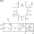
- the dual ring control method (or concept) is used in the United States, Australia and much of Asia and is based on FIG 5 exemplified as follows.
- Four intersecting streets 509, 511, 513 and 515 are shown.
- the streets 511 and 515 correspond to a main street ("Major Street”). Streets 509 and 513 correspond to a minor street.
- the orbital period is divided into two parts, which are separated from one another by two barriers 501 and 503.
- the signal groups (with 1 to 8 in FIG 5 numbered consecutively and also partially marked with the Greek capital Phi " ⁇ ”.), in American "phase” and equated with the lane groups (lanegroups), are arranged on two rings 505 and 507 in the sense of their green switching, which are analogous to old electromechanical ones Controls are processed.
- the reference numeral 508 shows an exemplary representation of an equivalent dual ring structure ("equivalent dual ring structure").
- the flow rates ("flow ratios") are in parentheses.
- the signal group arranged on a ring then has a green color when the "sliding contact", ie the current one Up to two signal groups can be created for each ring on each of the two sub-areas of the circulation, ie four for each sub-area as shown on the left with signal groups 1, 2, 5 and 6.
- the signal groups within a sub-area are arranged in such a way that the compatible signal groups of one signal group are arranged on the other ring, while hostile signal groups on the same ring.
- the signal group hitting one of the two boundaries (barrier) 501 and 503 must end with the barrier, whereby the time of the barrier can be determined adaptively as the switching time of the partial areas If there are two signal groups on a ring within a partial area, the time of switching between the two signal groups can be changed without considering other switching times as long as minimum signal times and intermediate times are observed. Accordingly, the switching time as in FIG 5 shown between signal group 2 and 1 may be different than between 5 and 6.
- FIG. 1 shows a flow chart of a method for controlling a light signal system.
- a first round trip time the measured traffic data are aggregated in a step 101 and signal times of a signal group of the traffic signal system are determined for a second round trip time following the first round trip time at the beginning of an intermediate third round trip time before the latest point in time has been reached.
- the determined signal times are kept unchanged after the determination.
- the signal group in the second round trip time is controlled based on the signal times kept unchanged, so that the signal group in the second round trip time outputs signals corresponding to the signal times kept unchanged.
- the light signal system comprises a plurality of signal groups, for which the respective analog signal times are determined and kept unchanged.
- FIG 2 shows a traffic light control system 201 for controlling a traffic light system (not shown).
- the traffic light control system 201 comprises a data transmission interface 203 for the acceptance of traffic data. This traffic data can be determined or recorded in particular by means of a traffic monitoring device and transferred to the data transmission interface 203.
- the traffic light control system 201 further comprises a traffic data processing unit 205 for determining traffic signal control data.
- the traffic light control system 201 comprises a data transfer interface 207 for transferring the traffic light control data to a traffic light control unit (not shown).
- the traffic light control system 201 comprises the traffic light control unit.
- FIG 3 shows a signal schedule 301 of a traffic signal system with signal groups SG1, SG2, SG3, SG4 and SG5.
- the traffic light system is located at a node.
- the node is therefore a signaled node.
- traffic data from five detectors Det1, Det2, Det3, Det4 and Det5 are shown symbolically as lines 302 with different lengths in the signal time schedule 301, the lines 302 marking the period of time that the detector was occupied by a vehicle.
- the duration of an occupancy depends on the speed of the vehicle and its length. Detectors with an effective length of up to two meters are preferably used for the invention, since these can still reliably differentiate between the individual vehicles, and so the traffic demand can be counted. With longer detectors, models can be used to decide, in the case of longer occupancy times, whether these were triggered by one or more vehicles.
- the detectors can be, for example, design detectors, requirement detectors or strategic detectors.
- Request detectors are immediately in front of the stop line and cannot be run over if the signal is blocked.
- Dimensioning detectors are at a distance of approx. 3 seconds travel time, i.e. in the range of approx. 40m-60m in front of the stop line and can only be passed over to a limited extent when the signal is blocked, and only until the queue in front of the blocked signal reaches the detector.
- Strategic detectors are so far in front of the stop line of the signal that the detector can be crossed by blocking the Signal is not hindered as long as the node is not overloaded. This means in particular that the detectors can be arranged on the roads leading to the node and on the node itself.
- Three round trip times 303, 305 and 307 are shown as examples in the signal schedule 301. In an embodiment not shown, more than three round trip times can be provided.
- the solid bold line 309 indicates a red signal.
- the double line with reference symbol 313 denotes a green signal, reference symbol 311 with the diagonal line denotes a yellow signal and reference symbol 310 with a bold line and diagonal line denotes a red yellow signal.
- a start of a red signal of the signal group SG4 is drawn in by means of a filled circle with the reference symbol 315.
- the individual signal times of the round trip times 303, 305, 307 of the signal time schedule 301 can be determined as a function of the traffic data that were determined or formed by means of the five detectors. As long as all signal times are always determined depending on the traffic data, it is generally not possible to display a remaining time for individual signals. For if, for example, a remaining time is to be displayed in the round-trip time 303 at a point in time 317 between the yellow phase and the red phase, this must not change afterwards, for example, shorten or lengthen. This will be the case, however, if the signal times based on the traffic data measured by the detectors are continuous, i.e.
- the traffic data is aggregated, at the beginning of the round trip time 305, the signal times of the signal groups for the round trip time 307 are determined and after determined, that is, unchanged. This is irrespective of which traffic data is still measured, for example, in the round trip time 305.
- the signal times of the signal groups in the round trip time 307 are thus known in advance.
- Remaining times for the individual signals of the signal groups can thus be determined or calculated for the round trip times 305 and 307 based on the recorded signal times. For example, at the beginning of a green phase of the signal group SG1, the corresponding remaining time can be displayed in the round trip time 305. The beginning of this green phase is identified by reference number 319. This means in particular that the signal times in the round trip time 307 are fixed and already known. These will therefore no longer change in the orbital period 307.
- the round trip time 307 can thus be referred to as the second round trip time.
- the round trip time 303 can thus be referred to as the first round trip time.
- the traffic data that are used to determine the signal times at the beginning of the third round time 305 or at the end of the first round time 303 can preferably be determined in the first round time 303.
- the beginning of a red phase in the orbital period 305 is identified by reference symbol 321.
- the latest point in time lies before this start 321 of this red phase, so that a remaining time for this red signal can be determined and displayed.
- the traffic data that are determined from measurement in the second round trip time 307 are compared with the forecast traffic data that were calculated or ascertained in the first round trip time 303 for the second round trip time 307 by the corresponding ones Determine signal times for the second round trip time 307. If there are any differences, in this way, these are taken into account for determining or determining signal times of further round-trip times that lie after the second round-trip time 307.
- FIG 4 shows a signaled node 401.
- 6 signal groups SG1, SG2, SG3, SG4, SG5 and SG6 are provided.
- 6 detectors Det1, Det2, Det3, Det4, Det5 and Det6 are also provided. Arrows are also drawn on the roads and signal groups to indicate a direction of travel to be traveled.
- FIG 4 also shows a signal plan 301 for the light signal system of the signaled node 401.
- the signal plan 301 according to FIG FIG 4 is essentially analogous to signal plan 301 according to FIG FIG 3 educated. Reference can be made to the corresponding explanations.
- reference numeral 411 also points to a phase profile. For the sake of clarity, the individual signal times for the round trip times 305 and 307 are not shown.
- Reference number 413 points to an aggregation interval that corresponds to the round trip time 303. This means that the traffic data 302 that were determined during the round trip time 303 are aggregated.
- the aggregation interval is therefore a circulation-related aggregation interval.
- the reference symbol 415 points to a calculation interval in which signal times for the round trip time 307 are determined.
- the calculation interval 415 lies in the round trip time 305.
- the signal times for the round trip time 307 are thus determined during the calculation interval (this is symbolically indicated by the arrow with the reference symbol 417).
- Reference numeral 421 shows an aggregation interval shifted by one phase.
- the calculation takes place in the calculation interval 423, which is also shifted by a phase, in which signal times for a likewise shifted round trip time 419a are determined, which are no longer changed for the duration of one phase, so that the signal groups are controlled in accordance with the signal times kept unchanged and in the Periods 417 and 423 the remaining times of the signals can be calculated.
- changes in the traffic flow can be determined after each phase and signal times can be calculated for the period after the duration of a round.
- the signal times after the calculation are only kept unchanged to the extent that they are already used to calculate remaining times. For common phase sequences, this is the period of the first phase of the period that begins one cycle after the end of the aggregation interval, in FIG 4 the first phase of interval 419a.
- Reference numeral 425 points to an aggregation interval shifted by a specific time period, here 1 s.
- reference numeral 427 points to a calculation interval in which signal times for interval 419b are determined, so that the remaining times of the signal groups in time ranges 417 and 427 can be calculated.
- the signal times are recalculated every second for a period after the duration of one revolution after the calculation starts, only such signal times being changed, that are not yet used for displaying remaining times or for other applications.
- the reference numeral 429 shows an example of an aggregation interval, which was temporally preferred to a control interval 431 following a certain time duration 433, in particular by a computing time that is required to determine the corresponding traffic signal control data based on the aggregated traffic data.
- the traffic light control data according to the time 433 are used to control the traffic light system in a control interval 435, which immediately follows the control interval 431. This means that the aggregation interval and the control interval are each offset by a predefined time duration, the aggregation interval is brought forward according to the time duration.
- This duration depends in particular on the computing time and / or on a parameter as has already been explained above, for example: aggregation time, transmission time of traffic signal control data from a data transfer interface 207 to a traffic signal control unit, response time of a traffic signal control unit in Respond to received traffic signal control data or any combination thereof.
- the latest point in time from which the switching times of the following cycle may no longer be changed is determined for each cycle time. This is the earliest point in time at which a signal is switched and then no longer switched in the rest of the cycle (green end of signals 1 and 2 in cycle 303).
- a number of round trip times (303, 305, 307) is inserted between the first round trip time and the second round trip time in order to determine the signal times even further in the future, for example for emergency vehicles, public transport vehicles and for individual road users in Context of a green wave.
- the invention therefore relates in particular to a method for controlling light signal groups in which signal times are calculated using traffic data and these signal data are calculated up to a point in time at the latest and then are no longer changed.
- the invention differs from the known prior art for estimating signal times and remaining times in particular in that the signal times are not estimated but calculated.
- the invention differs from the known prior art for displaying remaining times in particular in that the signal times during the operation of the light signal system are determined adaptively on the basis of the traffic data.
- One embodiment comprises displaying and / or using remaining times of the signaled signal images by aggregating the traffic data in one round and calculating signal times for a second round (round-trip time) in a first round, the time after the first round, in particular immediately after a third round following the first round.
- the calculation and transmission takes place, for example, in the time of the phase transition when the circulation (cycle time) starts with the phase transition in the first phase of the phase sequence. If the circulation is defined differently, a further embodiment specified below can be used, for example.
- a further embodiment for displaying and / or using the remaining signal image times determines circulation-like intervals in the manner of a rolling horizon, in that after each phase a first interval shifted by the duration of the phase ends and the signal times of a second interval from the traffic data aggregated for this interval can be calculated, which immediately follows a third interval between the first and second interval.
- the intervals defined in this way have the length of one round, but are shifted to this.
- the advantage of this procedure is that after every phase there is a change in traffic demand can be reacted, the signal times calculated therefrom being used at the earliest in the second interval.
- the phase transition takes place after each phase; the calculations and the transmission of the signal times can take place during this time. In the event that the duration of the phase transition is insufficient, a further embodiment described below is used.
- This further embodiment for displaying and using the signal image remaining times also uses this approach of the intervals, but these are calculated very frequently, for example every second instead of only after each phase.
- the advantage of this embodiment is that signals which can only be taken into account on request and not released in each round can also be taken into account if the remaining times for the non-released signal (red) are only displayed when the signal is requested , The second processing ensures that a remaining time can be calculated and displayed as quickly as possible after the request.
- Another embodiment of the method allows the coordination of vehicles, for example in the context of a green wave, in the context of prioritizing local public transport (bus, tram) for emergency vehicles such as ambulance, fire service, police and VIP.
- the signal times have to be calculated further or less in advance, depending on the respective planning and the location where the vehicles log in when calculating the signal times.
- the signal times must be calculated at least so far in advance that the vehicles can be informed as soon as they register whether and at what speed they will be released. If the registration occurs several rounds before the round for which it is to be released, special phases and signal sequences can be switched in preparation to avoid that the vehicles are obstructed by other road users by driving ahead Vehicles can drain in advance and vehicles turning into the route are prevented from turning.
- the first interval, the traffic data of which is aggregated is advanced so far that the aggregation of the traffic data and the calculation of the signal times can be carried out in the time gained, the signals can be transmitted to the signal processing and signaled in time. This prevents that signal times can no longer be implemented in time due to system-related computing times.
- the traffic requests for the second interval are predicted from the traffic data collected until the end of the first interval.
- the traffic requests (traffic data) measured during the second interval are compared with the forecast traffic requests (traffic data) and then at the end of this second interval, which is now the first interval of traffic data aggregation and signal time calculation, the signal times for the next second interval calculate and incorporate the difference from the forecast into the calculation, in particular to the effect that the signal times are additionally increased by the proportion that is required to serve the difference from the forecast and measurement of the traffic demand if the measured traffic demand was higher than that Measured and, due to the signal times being too short in the past interval, it is to be expected that not all traffic demand was served with the release time.
- the person skilled in the art can derive further embodiments with different requirements for the precalculation of the signal times, such as for example for transferring signal times to vehicles for their engine control, or for transferring signal times to road users for calculating an optimal movement trajectory (for example in the form of a recommended speed).
Landscapes
- Physics & Mathematics (AREA)
- General Physics & Mathematics (AREA)
- Traffic Control Systems (AREA)
Claims (20)
- Procédé de commande d'un dispositif de signalisation lumineux, dans lequel- dans un premier intervalle de temps du dispositif de signalisation lumineux, on détermine, sur la base de données (302) de trafic mesurées, des temps de signalisation d'un groupe (SG1, SG2, SG3, SG4) de signaux du dispositif de signalisation lumineux pendant un deuxième intervalle de temps suivant dans le temps le premier intervalle de temps,- dans lequel on maintient (103) inchangés, à partir d'un instant défini à l'avance, les temps de signalisation déterminés,- dans lequel on commande le groupe (SG1, SG2, SG3, SG4) de signaux dans le deuxième intervalle de temps, sur la base des temps de signalisation maintenus inchangés, de manière à ce que le groupe (SG1, SG2, SG3, SG4) de signaux émette, dans le deuxième intervalle de temps, des signalisations correspondant aux temps de signalisation maintenus inchangés,- dans lequel on détermine, à partir des temps de signalisation maintenus inchangés, des temps restants pour les formeurs des signalisations pour autant que les signalisations sont mises dans le deuxième intervalle de temps,- dans lequel on détermine l'instant défini à l'avance, de manière à ce que, pour des formeurs de signalisation en cours de fonctionnement du dispositif de signalisation lumineux, les temps restants déterminés pour chaque instant à venir restent inchangés, et de manière à ce que l'instant suivant de coupure d'une signalisation se trouve, au plus tard, à l'instant de l'instant précédent de coupure de la signalisation
- Procédé suivant la revendication 1, dans lequel le dispositif de signalisation lumineux a un temps de rotation défini.
- Procédé suivant la revendication 2, dans lequel on détermine une durée dans le temps des temps (303, 305, 307) de rotation pendant un fonctionnement du dispositif de signalisation en fonction de données (302) de trafic.
- Procédé suivant la revendication 2 ou 3, dans lequel le premier et/ou le deuxième intervalle de temps correspond, respectivement, correspondent à un temps de rotation.
- Procédé suivant la revendication 4, dans lequel l'instant défini à l'avance, pour des temps de coupure dans un temps de rotation, est l'instant le plus tôt où une signalisation est au rouge (arrêt) dans le temps de rotation précédent (= fin du groupe de signalisation), qui, dans le même temps de rotation précédent, n'a pas encore passé une fois au vert (voie libre).
- Procédé suivant l'une des revendications précédentes, dans lequel on détermine, pendant une durée définie à l'avance, de préférence pendant une seconde, les temps de coupure de la signalisation, pour lesquels les instants définis à l'avance ne se sont pas encore écoulés, de manière à ce que les temps de coupure de la signalisation puissent être encore modifiés et adaptés, afin de déplacer les intervalles de temps à la manière d'un rolling horizon de, respectivement, la durée définie à l'avance, pour pouvoir réagir plus rapidement à des modifications du déroulement du trafic.
- Procédé suivant l'une des revendications 1 à 4, dans lequel la commande des groupes de signalisation s'effectue suivant des phases et un calcul des instants de coupure est effectué sur la base d'instants de coupure de transition de phase.
- Procédé suivant la revendication 7, dans lequel l'instant défini à l'avance d'un intervalle de temps est la fin de la phase la plus tôt de l'intervalle de temps précédent où un signal est passé au rouge (arrêt), qui, dans le même intervalle de temps précédent, n'est pas encore passé une fois au vert (voie libre).
- Procédé suivant la revendication 8, dans lequel on détermine la durée définie à l'avance, de préférence les secondes, pour quel instant de coupure d'une transition de phase l'instant défini à l'avance ne s'est pas encore déroulé et peut être encore modifié et adapté de façon correspondante, pour décaler les intervalles de temps à la manière d'un rolling horizon de, respectivement, la durée définie à l'avance, afin de pouvoir réagir plus rapidement à des modifications du déroulement du trafic.
- Procédé suivant l'une des revendications 1 à 4, dans lequel la commande des groupes de signalisation s'effectue suivant le concept dual ring et on adapte des instants de coupure pour les limites, ainsi que les groupes de signalisation.
- Procédé suivant la revendication 10, dans lequel l'instant défini à l'avance d'un intervalle de temps est l'instant le plus tôt de l'intervalle de temps précédent, auquel un signal est passé au rouge (arrêt), qui, dans le même intervalle de temps précédent, n'est pas encore passé une fois au vert (voie libre).
- Procédé suivant la revendication 10 et 11, dans lequel on détermine la durée définie à l'avance, de préférence les secondes, pour quel instant de coupure d'une limite, l'instant le plus tard n'a pas encore eu lieu et, en conséquence, peut être encore modifié et adapté, en calculant, pour tous les groupes de signalisation concernés, respectivement, l'instant défini à l'avance et le plus tôt des instants de coupure définis à l'avance, qui s'en suivent des groupes de signalisation, est l'instant le plus tard dans le temps de la limite, pour décaler l'intervalle de temps à la manière d'un rolling horizon de, respectivement, la durée définie à l'avance, afin de pouvoir réagir plus rapidement à des variations du déroulement du trafic.
- Procédé suivant l'une des revendications précédentes, dans lequel on pronostique des données du trafic pendant le deuxième intervalle de temps, la détermination des temps (101) de signalisation s'effectuant en fonction des données de trafic pronostiquées, les données de trafic pronostiquées et des données de trafic réelles du deuxième intervalle de temps étant comparées entre elles, des temps de signalisation du groupe (SG1, SG2, SG3, SG4) de signalisation étant déterminés, en fonction de la comparaison, pour au moins un autre intervalle de temps, qui est dans le temps après le deuxième intervalle de temps.
- Procédé suivant l'une des revendications précédentes, dans lequel on préfère un intervalle d'agrégation, sur lequel les données (302) de trafic sont agrégées dans le temps, au premier intervalle (303) de temps, en fonction d'un paramètre, qui est au moins un élément choisi dans le groupe suivant de paramètres : temps d'agrégation, durée de calcul pour des temps de coupure adaptatifs, temps de transmission de données de commande de dispositifs de signalisation lumineux, d'une interface (207) de transmission de données à une unité de commande de dispositifs de signalisation lumineux, temps de réaction d'une unité de commande de dispositifs de signalisation lumineux reçus ou une combinaison quelconque de ceux-ci.
- Procédé suivant l'une des revendications précédentes, dans lequel, dans le calcul des instants de coupure, on prend en compte une coordination à des groupes de signalisation de nœuds voisins.
- Procédé suivant l'une des revendications précédentes dans la mesure où elle se rapporte à la revendication 14, dans lequel on détermine une durée dans le temps de l'intervalle d'agrégation individuellement pour chaque groupe (SG1, SG2, SG3, SG4) de signalisation du dispositif de signalisation lumineux du début du temps du début du temps vert au début du temps vert du groupe (SG1, SG2, SG3, SG4) de signalisation correspondant.
- Procédé suivant l'une des revendications précédentes, dans lequel on ne détermine pas de temps restant, au moins pour une signalisation dans au moins l'un des intervalles (303, 305, 307) de temps, tant que la signalisation est demandée.
- Procédé suivant l'une des revendications précédentes, dans lequel on insère un certain nombre d'intervalles (303, 305, 307) de temps entre le premier intervalle de temps et le deuxième intervalle de temps, pour fixer les temps de signalisation encore davantage à l'avenir.
- Système (201) de commande de dispositif de signalisation lumineux pour commander un dispositif de signalisation lumineux, comprenant :- une interface (203) de transmission de données pour prendre en charge des données (302) de trafic,- une unité (205) de traitement de données de trafic pour déterminer des données de commande de dispositifs de signalisation lumineux,- une interface (207) de transmission de données pour transmettre les données de commande de dispositifs de signalisation lumineux à une unité de commande de dispositifs de signalisation lumineux, dans lequel- l'unité (205) de traitement de données de trafic est constituée pour déterminer, dans un premier intervalle de temps du dispositif de signalisation lumineux, sur la base de données (302) de trafic mesurées, des temps de signalisation d'un groupe (SG1, SG2, SG3, SG4) de signalisation du dispositif de signalisation lumineuse pour un deuxième intervalle de temps suivant dans le temps le premier intervalle de temps, dans lequel- l'unité (205) de traitement de données de trafic est constituée pour maintenir inchangés les temps de signalisation déterminés, à partir d'un instant défini à l'avance, de manière à pouvoir commander les groupes (SG1, SG2, SG3, SG4) de signalisation dans le deuxième intervalle de temps, sur la base des temps de signalisation maintenus inchangés, de manière à ce que les groupes (SG1, SG2, SG3, SG4) de signalisation puissent, dans le deuxième intervalle de temps, émettre des signalisations correspondant aux temps de signalisation maintenus inchangés,- dans lequel l'unité (205) de traitement de données de trafic est constituée pour déterminer, à partir des temps de signalisation, des temps restants pour les formeurs des signalisation, dans la mesure où ils sont commutés dans le deuxième temps de rotation,- dans lequel l'unité (205) de traitement de données de trafic est constituée pour déterminer l'instant défini à l'avance, de manière à ce que, pour de formeurs de signalisation momentanément en fonctionnement, les temps restants déterminés pour chaque instant dans l'avenir restent inchangés et de manière à ce que l'instant de coupure suivant d'une signalisation soit au plus tard à l'instant de l'instant de coupure précédent.
- Programme d'ordinateur, comprenant un code de programme pour effectuer le procédé suivant l'une des revendications 1 à 18, lorsque le programme d'ordinateur est réalisé sur un ordinateur.
Priority Applications (1)
| Application Number | Priority Date | Filing Date | Title |
|---|---|---|---|
| PL15710754T PL3084746T3 (pl) | 2014-03-24 | 2015-03-12 | Sposób sterowania urządzeniem sygnalizacji świetlnej oraz system sterowania urządzeniem sygnalizacji świetlnej |
Applications Claiming Priority (2)
| Application Number | Priority Date | Filing Date | Title |
|---|---|---|---|
| DE102014205419 | 2014-03-24 | ||
| PCT/EP2015/055219 WO2015144445A1 (fr) | 2014-03-24 | 2015-03-12 | Procédé de commande d'un dispositif de signalisation lumineux et système de commande de dispositif de signalisation lumineux |
Publications (2)
| Publication Number | Publication Date |
|---|---|
| EP3084746A1 EP3084746A1 (fr) | 2016-10-26 |
| EP3084746B1 true EP3084746B1 (fr) | 2020-01-15 |
Family
ID=52692620
Family Applications (1)
| Application Number | Title | Priority Date | Filing Date |
|---|---|---|---|
| EP15710754.1A Active EP3084746B1 (fr) | 2014-03-24 | 2015-03-12 | Procédé de commande d'un dispositif de signalisation lumineux et système de commande de dispositif de signalisation lumineux |
Country Status (3)
| Country | Link |
|---|---|
| EP (1) | EP3084746B1 (fr) |
| PL (1) | PL3084746T3 (fr) |
| WO (1) | WO2015144445A1 (fr) |
Families Citing this family (3)
| Publication number | Priority date | Publication date | Assignee | Title |
|---|---|---|---|---|
| DE102015218942A1 (de) * | 2015-09-30 | 2017-03-30 | Siemens Aktiengesellschaft | Verfahren zum Steuern einer Anzeige einer Restzeit |
| CN108133604A (zh) * | 2018-02-06 | 2018-06-08 | 电子科技大学 | 一种基于流量特征的红绿灯动态实时调度方法 |
| CN117012056A (zh) * | 2023-07-21 | 2023-11-07 | 长安大学 | A-smgcs控制下机场场面交通信号配时方法、系统、设备及介质 |
Family Cites Families (7)
| Publication number | Priority date | Publication date | Assignee | Title |
|---|---|---|---|---|
| JP3399421B2 (ja) * | 1999-11-05 | 2003-04-21 | 住友電気工業株式会社 | 交通信号制御装置 |
| US6268805B1 (en) * | 1999-12-01 | 2001-07-31 | Damon Undrell Simon | Traffic light |
| CA2472514A1 (fr) * | 2004-06-25 | 2005-12-25 | Persio Walter Bortollot | Feu de circulation a information de minuterie |
| CN100504956C (zh) * | 2007-03-28 | 2009-06-24 | 无锡安邦电气有限公司 | 一种交通信号灯倒计时显示的控制方法 |
| US20100259419A1 (en) * | 2009-04-14 | 2010-10-14 | Russell Renner | Stoplight timer |
| CN101840637A (zh) * | 2010-04-20 | 2010-09-22 | 上海大学 | 基于图像处理的交通信号智能控制系统及方法 |
| DE102010052702B4 (de) * | 2010-11-26 | 2012-07-05 | Audi Ag | Verfahren zur Steuerung einer Lichtsignalanlage und zugehörige Lichtsignalanlage |
-
2015
- 2015-03-12 WO PCT/EP2015/055219 patent/WO2015144445A1/fr not_active Ceased
- 2015-03-12 EP EP15710754.1A patent/EP3084746B1/fr active Active
- 2015-03-12 PL PL15710754T patent/PL3084746T3/pl unknown
Non-Patent Citations (1)
| Title |
|---|
| None * |
Also Published As
| Publication number | Publication date |
|---|---|
| WO2015144445A1 (fr) | 2015-10-01 |
| EP3084746A1 (fr) | 2016-10-26 |
| PL3084746T3 (pl) | 2020-06-29 |
Similar Documents
| Publication | Publication Date | Title |
|---|---|---|
| DE102010052702B4 (de) | Verfahren zur Steuerung einer Lichtsignalanlage und zugehörige Lichtsignalanlage | |
| EP3223257B1 (fr) | Procédé et dispositif destinés à influencer un système de gestion du trafic | |
| DE102008035873A1 (de) | Verfahren zur Steuerung und Regelung des Verkehrsflusses | |
| EP3308369A1 (fr) | Procédé de commande de la circulation dans une zone de stationnement | |
| DE112012001799T5 (de) | Fahrassistenz-Vorrichtung | |
| DE102018216082A1 (de) | Verfahren zur kooperativen Manöverabstimmung | |
| DE102016013972A1 (de) | Fahrerassistenzsystem und -verfahren | |
| DE102014000432A1 (de) | Verfahren zum Betrieb eines zur wenigstens teilweise automatischen Fahrzeugführung ausgebildeten Fahrerassistenzsystems und Kraftfahrzeug | |
| DE102007056225A1 (de) | Verfahren und Vorrichtung zum Steuern eines Verkehrsflusses an einer Kreuzung | |
| EP3084746B1 (fr) | Procédé de commande d'un dispositif de signalisation lumineux et système de commande de dispositif de signalisation lumineux | |
| EP3151215A1 (fr) | Procede de commande d'un affichage d'un temps residuel | |
| DE102012214164B3 (de) | Verfahren und Vorrichtung zur dynamischen Steuerung mindestens einer Lichtsignalanlage | |
| DE102019211098B4 (de) | Verfahren, Vorrichtung und Computerprogramm zum Bestimmen einer Ampelphase einer Ampel einer Ampelanlage | |
| EP2527221A1 (fr) | Procédé d'opération d'un système d'assistance au conducteur de guidage longitudinal d'un véhicule automobile et véhicule automobile | |
| DE102011107663B4 (de) | Verfahren und Vorrichtung zur dynamischen Steuerung einer Signalanlage | |
| DE102014114535B4 (de) | Verfahren zur Steuerung von Lichtsignalanlagen (LSA) an Verkehrsknotenpunkten auf einem Fahrweg eines Einsatzfahrzeuges | |
| DE102015202434B4 (de) | Verfahren und Vorrichtung zur dynamischen Steuerung einer Signalanlage | |
| EP3113143A2 (fr) | Procede de determination d'une prediction du temps de commutation | |
| DE10025039C2 (de) | Verfahren zur Ermittlung von Verkehrsregelungsphasendauern | |
| EP2955483B1 (fr) | Procédé de calcul d'une conduite optimale de véhicule, en particulier d'une conduite de véhicule utilitaire | |
| EP2492886A1 (fr) | Procédé et système de commande d'installations de signaux lumineux pour la commande d'installations de signaux lumineux | |
| DE102015217529B4 (de) | Verfahren zur Steuerung einer Signalanlage einer Verkehrssteuerung | |
| DE102013101405B4 (de) | Ampelkommunikationsverfahren | |
| EP3113142A2 (fr) | Procede destine a la commande d'une installation de signaux | |
| EP1526493B1 (fr) | Procédé pour affichage de l'information routière dans un véhicule |
Legal Events
| Date | Code | Title | Description |
|---|---|---|---|
| PUAI | Public reference made under article 153(3) epc to a published international application that has entered the european phase |
Free format text: ORIGINAL CODE: 0009012 |
|
| 17P | Request for examination filed |
Effective date: 20160722 |
|
| AK | Designated contracting states |
Kind code of ref document: A1 Designated state(s): AL AT BE BG CH CY CZ DE DK EE ES FI FR GB GR HR HU IE IS IT LI LT LU LV MC MK MT NL NO PL PT RO RS SE SI SK SM TR |
|
| AX | Request for extension of the european patent |
Extension state: BA ME |
|
| RIN1 | Information on inventor provided before grant (corrected) |
Inventor name: REINTS, WILKE Inventor name: MUECK, JUERGEN Inventor name: YETIK, GOERKEM Inventor name: WUNDER, ROLAND Inventor name: JOHN, ALEXANDER Inventor name: POSCHINGER, ANDREAS |
|
| DAV | Request for validation of the european patent (deleted) | ||
| DAX | Request for extension of the european patent (deleted) | ||
| RAP1 | Party data changed (applicant data changed or rights of an application transferred) |
Owner name: SIEMENS AKTIENGESELLSCHAFT |
|
| RAP1 | Party data changed (applicant data changed or rights of an application transferred) |
Owner name: SIEMENS MOBILITY GMBH |
|
| GRAP | Despatch of communication of intention to grant a patent |
Free format text: ORIGINAL CODE: EPIDOSNIGR1 |
|
| STAA | Information on the status of an ep patent application or granted ep patent |
Free format text: STATUS: GRANT OF PATENT IS INTENDED |
|
| INTG | Intention to grant announced |
Effective date: 20190920 |
|
| GRAS | Grant fee paid |
Free format text: ORIGINAL CODE: EPIDOSNIGR3 |
|
| GRAA | (expected) grant |
Free format text: ORIGINAL CODE: 0009210 |
|
| STAA | Information on the status of an ep patent application or granted ep patent |
Free format text: STATUS: THE PATENT HAS BEEN GRANTED |
|
| AK | Designated contracting states |
Kind code of ref document: B1 Designated state(s): AL AT BE BG CH CY CZ DE DK EE ES FI FR GB GR HR HU IE IS IT LI LT LU LV MC MK MT NL NO PL PT RO RS SE SI SK SM TR |
|
| REG | Reference to a national code |
Ref country code: CH Ref legal event code: EP Ref country code: GB Ref legal event code: FG4D Free format text: NOT ENGLISH |
|
| REG | Reference to a national code |
Ref country code: IE Ref legal event code: FG4D Free format text: LANGUAGE OF EP DOCUMENT: GERMAN |
|
| REG | Reference to a national code |
Ref country code: DE Ref legal event code: R096 Ref document number: 502015011528 Country of ref document: DE |
|
| REG | Reference to a national code |
Ref country code: AT Ref legal event code: REF Ref document number: 1225831 Country of ref document: AT Kind code of ref document: T Effective date: 20200215 |
|
| REG | Reference to a national code |
Ref country code: CH Ref legal event code: NV Representative=s name: SIEMENS SCHWEIZ AG, CH |
|
| REG | Reference to a national code |
Ref country code: NL Ref legal event code: MP Effective date: 20200115 |
|
| REG | Reference to a national code |
Ref country code: LT Ref legal event code: MG4D |
|
| PG25 | Lapsed in a contracting state [announced via postgrant information from national office to epo] |
Ref country code: NL Free format text: LAPSE BECAUSE OF FAILURE TO SUBMIT A TRANSLATION OF THE DESCRIPTION OR TO PAY THE FEE WITHIN THE PRESCRIBED TIME-LIMIT Effective date: 20200115 Ref country code: FI Free format text: LAPSE BECAUSE OF FAILURE TO SUBMIT A TRANSLATION OF THE DESCRIPTION OR TO PAY THE FEE WITHIN THE PRESCRIBED TIME-LIMIT Effective date: 20200115 Ref country code: PT Free format text: LAPSE BECAUSE OF FAILURE TO SUBMIT A TRANSLATION OF THE DESCRIPTION OR TO PAY THE FEE WITHIN THE PRESCRIBED TIME-LIMIT Effective date: 20200607 Ref country code: NO Free format text: LAPSE BECAUSE OF FAILURE TO SUBMIT A TRANSLATION OF THE DESCRIPTION OR TO PAY THE FEE WITHIN THE PRESCRIBED TIME-LIMIT Effective date: 20200415 Ref country code: RS Free format text: LAPSE BECAUSE OF FAILURE TO SUBMIT A TRANSLATION OF THE DESCRIPTION OR TO PAY THE FEE WITHIN THE PRESCRIBED TIME-LIMIT Effective date: 20200115 |
|
| PG25 | Lapsed in a contracting state [announced via postgrant information from national office to epo] |
Ref country code: GR Free format text: LAPSE BECAUSE OF FAILURE TO SUBMIT A TRANSLATION OF THE DESCRIPTION OR TO PAY THE FEE WITHIN THE PRESCRIBED TIME-LIMIT Effective date: 20200416 Ref country code: HR Free format text: LAPSE BECAUSE OF FAILURE TO SUBMIT A TRANSLATION OF THE DESCRIPTION OR TO PAY THE FEE WITHIN THE PRESCRIBED TIME-LIMIT Effective date: 20200115 Ref country code: SE Free format text: LAPSE BECAUSE OF FAILURE TO SUBMIT A TRANSLATION OF THE DESCRIPTION OR TO PAY THE FEE WITHIN THE PRESCRIBED TIME-LIMIT Effective date: 20200115 Ref country code: IS Free format text: LAPSE BECAUSE OF FAILURE TO SUBMIT A TRANSLATION OF THE DESCRIPTION OR TO PAY THE FEE WITHIN THE PRESCRIBED TIME-LIMIT Effective date: 20200515 Ref country code: LV Free format text: LAPSE BECAUSE OF FAILURE TO SUBMIT A TRANSLATION OF THE DESCRIPTION OR TO PAY THE FEE WITHIN THE PRESCRIBED TIME-LIMIT Effective date: 20200115 Ref country code: BG Free format text: LAPSE BECAUSE OF FAILURE TO SUBMIT A TRANSLATION OF THE DESCRIPTION OR TO PAY THE FEE WITHIN THE PRESCRIBED TIME-LIMIT Effective date: 20200415 |
|
| REG | Reference to a national code |
Ref country code: DE Ref legal event code: R097 Ref document number: 502015011528 Country of ref document: DE |
|
| PG25 | Lapsed in a contracting state [announced via postgrant information from national office to epo] |
Ref country code: EE Free format text: LAPSE BECAUSE OF FAILURE TO SUBMIT A TRANSLATION OF THE DESCRIPTION OR TO PAY THE FEE WITHIN THE PRESCRIBED TIME-LIMIT Effective date: 20200115 Ref country code: SM Free format text: LAPSE BECAUSE OF FAILURE TO SUBMIT A TRANSLATION OF THE DESCRIPTION OR TO PAY THE FEE WITHIN THE PRESCRIBED TIME-LIMIT Effective date: 20200115 Ref country code: DK Free format text: LAPSE BECAUSE OF FAILURE TO SUBMIT A TRANSLATION OF THE DESCRIPTION OR TO PAY THE FEE WITHIN THE PRESCRIBED TIME-LIMIT Effective date: 20200115 Ref country code: LT Free format text: LAPSE BECAUSE OF FAILURE TO SUBMIT A TRANSLATION OF THE DESCRIPTION OR TO PAY THE FEE WITHIN THE PRESCRIBED TIME-LIMIT Effective date: 20200115 Ref country code: RO Free format text: LAPSE BECAUSE OF FAILURE TO SUBMIT A TRANSLATION OF THE DESCRIPTION OR TO PAY THE FEE WITHIN THE PRESCRIBED TIME-LIMIT Effective date: 20200115 Ref country code: CZ Free format text: LAPSE BECAUSE OF FAILURE TO SUBMIT A TRANSLATION OF THE DESCRIPTION OR TO PAY THE FEE WITHIN THE PRESCRIBED TIME-LIMIT Effective date: 20200115 Ref country code: ES Free format text: LAPSE BECAUSE OF FAILURE TO SUBMIT A TRANSLATION OF THE DESCRIPTION OR TO PAY THE FEE WITHIN THE PRESCRIBED TIME-LIMIT Effective date: 20200115 Ref country code: SK Free format text: LAPSE BECAUSE OF FAILURE TO SUBMIT A TRANSLATION OF THE DESCRIPTION OR TO PAY THE FEE WITHIN THE PRESCRIBED TIME-LIMIT Effective date: 20200115 Ref country code: MC Free format text: LAPSE BECAUSE OF FAILURE TO SUBMIT A TRANSLATION OF THE DESCRIPTION OR TO PAY THE FEE WITHIN THE PRESCRIBED TIME-LIMIT Effective date: 20200115 |
|
| PLBE | No opposition filed within time limit |
Free format text: ORIGINAL CODE: 0009261 |
|
| STAA | Information on the status of an ep patent application or granted ep patent |
Free format text: STATUS: NO OPPOSITION FILED WITHIN TIME LIMIT |
|
| 26N | No opposition filed |
Effective date: 20201016 |
|
| REG | Reference to a national code |
Ref country code: BE Ref legal event code: MM Effective date: 20200331 |
|
| PG25 | Lapsed in a contracting state [announced via postgrant information from national office to epo] |
Ref country code: LU Free format text: LAPSE BECAUSE OF NON-PAYMENT OF DUE FEES Effective date: 20200312 |
|
| PG25 | Lapsed in a contracting state [announced via postgrant information from national office to epo] |
Ref country code: IE Free format text: LAPSE BECAUSE OF NON-PAYMENT OF DUE FEES Effective date: 20200312 Ref country code: IT Free format text: LAPSE BECAUSE OF FAILURE TO SUBMIT A TRANSLATION OF THE DESCRIPTION OR TO PAY THE FEE WITHIN THE PRESCRIBED TIME-LIMIT Effective date: 20200115 |
|
| PG25 | Lapsed in a contracting state [announced via postgrant information from national office to epo] |
Ref country code: SI Free format text: LAPSE BECAUSE OF FAILURE TO SUBMIT A TRANSLATION OF THE DESCRIPTION OR TO PAY THE FEE WITHIN THE PRESCRIBED TIME-LIMIT Effective date: 20200115 Ref country code: BE Free format text: LAPSE BECAUSE OF NON-PAYMENT OF DUE FEES Effective date: 20200331 |
|
| GBPC | Gb: european patent ceased through non-payment of renewal fee |
Effective date: 20200415 |
|
| PG25 | Lapsed in a contracting state [announced via postgrant information from national office to epo] |
Ref country code: GB Free format text: LAPSE BECAUSE OF NON-PAYMENT OF DUE FEES Effective date: 20200415 |
|
| REG | Reference to a national code |
Ref country code: DE Ref legal event code: R081 Ref document number: 502015011528 Country of ref document: DE Owner name: YUNEX GMBH, DE Free format text: FORMER OWNER: SIEMENS MOBILITY GMBH, 81739 MUENCHEN, DE |
|
| PG25 | Lapsed in a contracting state [announced via postgrant information from national office to epo] |
Ref country code: TR Free format text: LAPSE BECAUSE OF FAILURE TO SUBMIT A TRANSLATION OF THE DESCRIPTION OR TO PAY THE FEE WITHIN THE PRESCRIBED TIME-LIMIT Effective date: 20200115 Ref country code: MT Free format text: LAPSE BECAUSE OF FAILURE TO SUBMIT A TRANSLATION OF THE DESCRIPTION OR TO PAY THE FEE WITHIN THE PRESCRIBED TIME-LIMIT Effective date: 20200115 Ref country code: CY Free format text: LAPSE BECAUSE OF FAILURE TO SUBMIT A TRANSLATION OF THE DESCRIPTION OR TO PAY THE FEE WITHIN THE PRESCRIBED TIME-LIMIT Effective date: 20200115 |
|
| PG25 | Lapsed in a contracting state [announced via postgrant information from national office to epo] |
Ref country code: MK Free format text: LAPSE BECAUSE OF FAILURE TO SUBMIT A TRANSLATION OF THE DESCRIPTION OR TO PAY THE FEE WITHIN THE PRESCRIBED TIME-LIMIT Effective date: 20200115 Ref country code: AL Free format text: LAPSE BECAUSE OF FAILURE TO SUBMIT A TRANSLATION OF THE DESCRIPTION OR TO PAY THE FEE WITHIN THE PRESCRIBED TIME-LIMIT Effective date: 20200115 |
|
| PG25 | Lapsed in a contracting state [announced via postgrant information from national office to epo] |
Ref country code: FR Free format text: LAPSE BECAUSE OF NON-PAYMENT OF DUE FEES Effective date: 20200331 |
|
| REG | Reference to a national code |
Ref country code: DE Ref legal event code: R082 Ref document number: 502015011528 Country of ref document: DE Representative=s name: PATENTANWALTSKANZLEI WILHELM & BECK, DE |
|
| REG | Reference to a national code |
Ref country code: AT Ref legal event code: PC Ref document number: 1225831 Country of ref document: AT Kind code of ref document: T Owner name: YUNEX GMBH, DE Effective date: 20220719 |
|
| PGFP | Annual fee paid to national office [announced via postgrant information from national office to epo] |
Ref country code: CH Payment date: 20250401 Year of fee payment: 11 |
|
| REG | Reference to a national code |
Ref country code: CH Ref legal event code: U11 Free format text: ST27 STATUS EVENT CODE: U-0-0-U10-U11 (AS PROVIDED BY THE NATIONAL OFFICE) Effective date: 20260401 |
|
| PGFP | Annual fee paid to national office [announced via postgrant information from national office to epo] |
Ref country code: DE Payment date: 20260219 Year of fee payment: 12 |
|
| PGFP | Annual fee paid to national office [announced via postgrant information from national office to epo] |
Ref country code: AT Payment date: 20260319 Year of fee payment: 12 |
|
| PGFP | Annual fee paid to national office [announced via postgrant information from national office to epo] |
Ref country code: PL Payment date: 20260227 Year of fee payment: 12 |