EP3085275A1 - Ensemble pivotant - Google Patents
Ensemble pivotant Download PDFInfo
- Publication number
- EP3085275A1 EP3085275A1 EP16163711.1A EP16163711A EP3085275A1 EP 3085275 A1 EP3085275 A1 EP 3085275A1 EP 16163711 A EP16163711 A EP 16163711A EP 3085275 A1 EP3085275 A1 EP 3085275A1
- Authority
- EP
- European Patent Office
- Prior art keywords
- piston
- working chamber
- connection
- auxiliary
- pivoting
- Prior art date
- Legal status (The legal status is an assumption and is not a legal conclusion. Google has not performed a legal analysis and makes no representation as to the accuracy of the status listed.)
- Granted
Links
Images

Classifications
-
- A—HUMAN NECESSITIES
- A47—FURNITURE; DOMESTIC ARTICLES OR APPLIANCES; COFFEE MILLS; SPICE MILLS; SUCTION CLEANERS IN GENERAL
- A47C—CHAIRS; SOFAS; BEDS
- A47C17/00—Sofas; Couches; Beds
- A47C17/38—Wall beds
- A47C17/40—Wall beds having balancing members, e.g. weights, springs
-
- F—MECHANICAL ENGINEERING; LIGHTING; HEATING; WEAPONS; BLASTING
- F16—ENGINEERING ELEMENTS AND UNITS; GENERAL MEASURES FOR PRODUCING AND MAINTAINING EFFECTIVE FUNCTIONING OF MACHINES OR INSTALLATIONS; THERMAL INSULATION IN GENERAL
- F16F—SPRINGS; SHOCK-ABSORBERS; MEANS FOR DAMPING VIBRATION
- F16F9/00—Springs, vibration-dampers, shock-absorbers, or similarly-constructed movement-dampers using a fluid or the equivalent as damping medium
- F16F9/02—Springs, vibration-dampers, shock-absorbers, or similarly-constructed movement-dampers using a fluid or the equivalent as damping medium using gas only or vacuum
- F16F9/0209—Telescopic
-
- A—HUMAN NECESSITIES
- A47—FURNITURE; DOMESTIC ARTICLES OR APPLIANCES; COFFEE MILLS; SPICE MILLS; SUCTION CLEANERS IN GENERAL
- A47C—CHAIRS; SOFAS; BEDS
- A47C17/00—Sofas; Couches; Beds
- A47C17/52—Cabinet beds; Table beds, or like beds; Wardrobe beds
-
- A—HUMAN NECESSITIES
- A47—FURNITURE; DOMESTIC ARTICLES OR APPLIANCES; COFFEE MILLS; SPICE MILLS; SUCTION CLEANERS IN GENERAL
- A47C—CHAIRS; SOFAS; BEDS
- A47C17/00—Sofas; Couches; Beds
- A47C17/86—Parts or details specially adapted for beds, sofas or couches not fully covered by any single one of groups A47C17/02 - A47C17/84
-
- F—MECHANICAL ENGINEERING; LIGHTING; HEATING; WEAPONS; BLASTING
- F16—ENGINEERING ELEMENTS AND UNITS; GENERAL MEASURES FOR PRODUCING AND MAINTAINING EFFECTIVE FUNCTIONING OF MACHINES OR INSTALLATIONS; THERMAL INSULATION IN GENERAL
- F16F—SPRINGS; SHOCK-ABSORBERS; MEANS FOR DAMPING VIBRATION
- F16F9/00—Springs, vibration-dampers, shock-absorbers, or similarly-constructed movement-dampers using a fluid or the equivalent as damping medium
- F16F9/02—Springs, vibration-dampers, shock-absorbers, or similarly-constructed movement-dampers using a fluid or the equivalent as damping medium using gas only or vacuum
- F16F9/0209—Telescopic
- F16F9/0218—Mono-tubular units
-
- F—MECHANICAL ENGINEERING; LIGHTING; HEATING; WEAPONS; BLASTING
- F16—ENGINEERING ELEMENTS AND UNITS; GENERAL MEASURES FOR PRODUCING AND MAINTAINING EFFECTIVE FUNCTIONING OF MACHINES OR INSTALLATIONS; THERMAL INSULATION IN GENERAL
- F16F—SPRINGS; SHOCK-ABSORBERS; MEANS FOR DAMPING VIBRATION
- F16F9/00—Springs, vibration-dampers, shock-absorbers, or similarly-constructed movement-dampers using a fluid or the equivalent as damping medium
- F16F9/32—Details
- F16F9/50—Special means providing automatic damping adjustment, i.e. self-adjustment of damping by particular sliding movements of a valve element, other than flexions or displacement of valve discs; Special means providing self-adjustment of spring characteristics
- F16F9/516—Special means providing automatic damping adjustment, i.e. self-adjustment of damping by particular sliding movements of a valve element, other than flexions or displacement of valve discs; Special means providing self-adjustment of spring characteristics resulting in the damping effects during contraction being different from the damping effects during extension, i.e. responsive to the direction of movement
-
- F—MECHANICAL ENGINEERING; LIGHTING; HEATING; WEAPONS; BLASTING
- F16—ENGINEERING ELEMENTS AND UNITS; GENERAL MEASURES FOR PRODUCING AND MAINTAINING EFFECTIVE FUNCTIONING OF MACHINES OR INSTALLATIONS; THERMAL INSULATION IN GENERAL
- F16F—SPRINGS; SHOCK-ABSORBERS; MEANS FOR DAMPING VIBRATION
- F16F9/00—Springs, vibration-dampers, shock-absorbers, or similarly-constructed movement-dampers using a fluid or the equivalent as damping medium
- F16F9/32—Details
- F16F9/58—Stroke limiting stops, e.g. arranged on the piston rod outside the cylinder
- F16F9/585—Stroke limiting stops, e.g. arranged on the piston rod outside the cylinder within the cylinder, in contact with working fluid
Definitions
- the invention relates to a pivoting arrangement with a pivoting element which is pivotable between a vertically upwardly directed rest position and a horizontally directed operating position about a pivot axis arranged at its one end region, wherein the pivoting movement of the pivoting element can be assisted and damped by a gas pressure spring.
- the swivel element is a swivel bed which can be folded out of its upwardly directed rest position into its horizontally directed sleeping position or folded out of its sleeping position into its rest position.
- two gas springs are arranged in opposite directions.
- This swivel assembly has a complex structure and requires a large amount of space.
- the object of the invention is therefore to provide a pivoting arrangement of the type mentioned, which is simple and requires a small space.
- the extended in the rest position and the operating position retracted gas spring has a cylinder filled with a pressurized gas cylinder, the interior of which is divided by a displaceable piston in a first working chamber and a second working chamber and the piston on one side Piston rod, which is guided through the second working chamber and a guide and sealing unit sealed to the outside, with an opened on an outward stroke of the piston, leading from the second working chamber to the first working chamber first connection and an inward stroke of the piston of the first Working chamber leading to the second working chamber second passage smaller passage cross-section than the passage cross-section of the first connection, with a displaceably arranged in the cylinder and on the piston rod auxiliary piston, the second working chamber on their r side remote from the piston separates from an auxiliary chamber formed in the cylinder, with a third in the Endausfahrhub Scheme of the piston opened third connection from the auxiliary chamber to the second working chamber and an opened in the retraction of the piston fourth connection of the second working chamber to the auxiliary chamber, wherein the
- this swivel arrangement according to the invention is pivoted from its upwardly directed rest position into its horizontal operating position, the piston rod with the piston moves into the cylinder. Only the second connection leading from the first working chamber to the second working chamber is opened. Due to their lower passage cross-section, this pivotal movement is damped. This also increases the pressure in the first working chamber, which forms an additional resistance especially on the second half of the pivoting path. The swivel element comes so softly damped in its operating position.
- the auxiliary piston must be moved from the piston in the Endausfahrhub to the fully extended position of the piston and piston rod and the present in the auxiliary chamber pressure gas flow through the third connection to the second working chamber.
- this is damped, since the passage cross-section of the third connection is made smaller.
- the gas spring extends in or parallel to the pivot plane of the pivot member and is articulated at one end to a stationary first bearing point and at its other end to a second bearing point on the pivot member, wherein the pivot member is a two-armed Lever forms, the first lever arm of greater extension forms a functional element and the second lever arm forms a hinge element on which the second bearing point is arranged at a distance from the pivot axis.
- the stationary first bearing point is arranged above the pivot axis at a distance from the rest position of the pivoting element on the side remote from the pivoting range of the pivoting element, very little installation space is required.
- the auxiliary piston In order to move the auxiliary piston back to the second working chamber around the Endausfahrhub Scheme back to the second working chamber at a retraction of the piston rod and piston from its fully extended position, the auxiliary piston be acted upon by a restoring force in a Endausfahrhub Schemesposition remote from the guide and sealing unit.
- a piston rod is arranged at a radial distance helical compression spring is arranged, with its one end to the guide and sealing unit or one of the guide and sealing unit near, cylinder-fixed stop is supported and with its other end the Applied auxiliary piston in the Endausfahrhub Schlosposition.
- the helical compression spring has only one, for moving the auxiliary piston sufficient, small force.
- the piston may have a radially encircling annular groove in which a sealing ring is arranged smaller axial extent than the axial width of the annular groove, which is sealingly against the inner wall of the cylinder with its radially outer surface in abutment, between his radially inner circumferential surface and the bottom of the annular groove an annular gap is formed, which permanently with connected to the first working chamber, with one or more in the second working chamber nearer side wall of the annular groove formed, the annular groove open throttle grooves whose groove openings of the sealing ring or an annular disc connected to the sealing ring can be covered.
- the sealing ring shifts to rest against the first working chamber nearer side wall of the annular groove. Since the annular gap is permanently connected to the first working chamber and the sealing ring or the annular disc connected to the sealing ring is lifted from the side wall closer to the second working chamber, this forms the first connection with a larger passage cross section.
- the sealing ring or the annular disk connected to the sealing ring bears against the side wall closer to the second working chamber, so that the annular gap permanently connected to the first working chamber is connected to the second working chamber only via the throttling grooves having a smaller passage cross section.
- the second connection is formed with a smaller passage cross-section.
- the auxiliary piston can be performed sealed in the cylinder and having a coaxially continuous guide bore, with which the auxiliary piston is displaceably guided on the piston rod, wherein the third connection is formed by an annular gap between the piston rod and the guide bore.
- the second working chamber facing groove openings are covered when the piston to the auxiliary piston of the piston, wherein the second working chamber with the radially outer ends of the other Drosselutenuten is connectable.
- the auxiliary piston may have at its radially circumferential surface a radially encircling sealing groove in which a fitting on the inner wall of the cylinder second sealing ring is arranged.
- the pivoting element is a pivotal bed, which is pivotable when not in use in a vertically upwardly directed rest position, in particular in a cabinet-like body. To use then takes place a pivoting in a horizontal operating position.
- the pivoting from the rest position to the operating position also takes place by manual force with the support of the gas spring. In the end region of the pivoting movement, this is damped by the gas spring so that the swivel bed softly dampened reaches the rest position and does not stick firmly to the cabinet-like body.
- pivot assembly is shown with a continuous line in a horizontal operating position and me broken line in a vertically upwardly directed rest position and has a two-armed lever formed pivoting element 1, which is pivotally mounted about a fixed pivot axis 2.
- the pivoting element consists of a first lever arm 3 of greater extent and a second lever arm 4 of small extent.
- a gas spring 5 is arranged, the free end of the piston rod 10 is articulated at a second bearing point 6 on the second lever arm 4 at a distance from the pivot axis 2.
- the piston rod 10 opposite end of the cylinder 7 of the gas spring 5 is hinged to a stationary bearing 8, which is located above the pivot axis 2 and at a distance to the rest position of the pivot member 1 on the pivot region 9 side facing away. This distance corresponds approximately to the distance of the second bearing point to the pivot axis, so that the gas spring 5 in the Operating position of the pivoting element 1 is aligned approximately vertically.
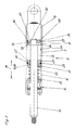
- Gas spring 5 is shown in detail in the gas filled with a pressurized gas cylinder 7, a piston 11 axially slidably disposed on which the projecting into the cylinder 7 end of the piston rod 10 is fixed.
- the piston 11 divides the interior of the cylinder 7 in a piston rod 10 facing away from the first working chamber 12 and a piston rod side second working chamber 13.
- the piston rod 10 is guided by the second working chamber 13 and a guide and sealing unit 14 sealed to the outside.
- an auxiliary piston 15 is further arranged displaceably, which separates the second working chamber 13 on its side facing away from the piston of an auxiliary chamber 16 formed in the cylinder 7.
- the auxiliary piston 15 has a continuous coaxial guide bore 17 through which the piston rod 10 is passed, wherein between the piston rod 10 and the guide bore 17, an annular gap 18 is formed is. About the annular gap 18, the two sides of the auxiliary piston 15 are interconnected.
- FIG. 1 is the auxiliary piston 15 with its second working chamber 13 facing end about a Endausfahrhub Scheme 19 spaced from the region of the guide and sealing unit 14 and is acted upon in this position by one end of a helical compression spring 20.
- the helical compression spring 20 surrounds the piston rod 10 in the auxiliary chamber 16 at a radial distance and is supported at its other end on a support disk 21, which is fixedly arranged in the cylinder 7 at the end of the auxiliary chamber 16 facing away from the piston 11.
- the auxiliary piston 15 has at its radially circumferential lateral surface on a radially circumferential sealing groove 22 in which a second sealing ring 23 is arranged, which prevents a connection between the two axial sides of the auxiliary piston 15 between the auxiliary piston 15 and the inner wall 24 of the cylinder 7.
- the auxiliary piston 15 On its end face facing the piston 11, the auxiliary piston 15 has radially passing second throttle grooves 25 whose total passage cross-section is smaller than the passage cross-section of the annular gap 18.
- the piston 11 has at its radially circumferential surface a radially encircling annular groove 26, in which a first sealing ring 27 lesser axial extent than the axial width of the annular groove 26 is arranged, so that the first sealing ring 27 between the two side walls of the annular groove 26 is movable , With its radially encircling outer circumferential surface of the first sealing ring 27 is in sealing engagement with the inner wall 24 of the cylinder. 7
- a second annular gap 28 is formed between the radially inner circumferential surface of the first sealing ring 27 and the bottom of the annular groove 26 .
- the first working chamber 12 facing side wall of the annular groove 26 is formed by a star disk 29 whose beam gaps 30 connect the second annular gap 28 permanently with a large cross-section with the first working chamber 12.
- first throttle grooves 31 are formed.
- annular disk 32 is arranged on the first sealing ring 27, through which the openings of the throttling grooves 31 directed towards the annular groove 26 are covered when the first sealing ring 27 is in its closer position to the second working chamber 13.
- the second annular gap 28 in the annular groove 26 is connected radially outwards only via the first throttle grooves 31 having a smaller passage cross-section with a third annular gap 34 between the outer jacket surface of the piston and the inner wall 24 of the cylinder 7 and thus with the second working chamber 13.
- the annular disk 32 connected to the first sealing ring 27 abuts against the second working chamber 13 closer side wall 33, so that the permanently connected to the first working chamber 12 second annular gap 28 only on the one lower Passage cross-section having first throttling grooves 31 is connected to the second working chamber 13.
- one of the first working chamber 12 to the second working chamber 13 leading second connection is formed with a smaller passage cross-section, so that the movement of the pivot member 1 is made attenuated from its vertical position in its horizontal position.
- the piston 11 lifts right from the beginning of the retraction of the auxiliary piston 15, so that compressed gas can flow largely unattenuated through the third compound forming an annular gap 18 from the auxiliary chamber 16 to the second working chamber 13.
- the helical compression spring 20 which has only small force, the auxiliary piston 15 is thereby moved to its Endausfahrhubposition.
- the first sealing ring 27 shifts to rest against the first working chamber 12 closer star wheel 29 of the annular groove 26. Since the second annular gap 28 is permanently connected to the first working chamber 12 via the beam gaps 30 and connected to the sealing ring 27 annular disk 32nd is lifted from the second working chamber 13 nearer side wall 33, thereby forming a first connection with a larger passage cross-section, so that initially takes place at least largely undamped pivotal movement of the pivot member 1 from its horizontal to its vertical position.
- the piston 11 comes into abutment against the piston 11 facing the end face of the auxiliary piston 15, so that only one fourth connection forming flow possibility of the compressed gas from the second working chamber 13 through the second throttle grooves 25 and the annular gap 18th to the auxiliary chamber 16 is present.
- the throttling grooves 25 lead to a damped outward movement in Endausfahrhub Scheme 19 of the piston 11 and piston rod 10th
Landscapes
- Engineering & Computer Science (AREA)
- General Engineering & Computer Science (AREA)
- Mechanical Engineering (AREA)
- Health & Medical Sciences (AREA)
- General Health & Medical Sciences (AREA)
- Nursing (AREA)
- Fluid-Damping Devices (AREA)
- Actuator (AREA)
Applications Claiming Priority (1)
| Application Number | Priority Date | Filing Date | Title |
|---|---|---|---|
| DE102015106134.1A DE102015106134A1 (de) | 2015-04-22 | 2015-04-22 | Schwenkanordnung |
Publications (2)
| Publication Number | Publication Date |
|---|---|
| EP3085275A1 true EP3085275A1 (fr) | 2016-10-26 |
| EP3085275B1 EP3085275B1 (fr) | 2017-09-27 |
Family
ID=55697045
Family Applications (1)
| Application Number | Title | Priority Date | Filing Date |
|---|---|---|---|
| EP16163711.1A Active EP3085275B1 (fr) | 2015-04-22 | 2016-04-04 | Ensemble pivotant |
Country Status (6)
| Country | Link |
|---|---|
| US (1) | US10463159B2 (fr) |
| EP (1) | EP3085275B1 (fr) |
| CN (1) | CN106065913B (fr) |
| DE (1) | DE102015106134A1 (fr) |
| ES (1) | ES2646542T3 (fr) |
| PT (1) | PT3085275T (fr) |
Families Citing this family (2)
| Publication number | Priority date | Publication date | Assignee | Title |
|---|---|---|---|---|
| IT201600120229A1 (it) * | 2016-11-28 | 2018-05-28 | Tecnoservice Kg/Sas D Wegleiter H & Co | dispositivo per l'areazione di coperte e simile |
| JP2020016287A (ja) * | 2018-07-25 | 2020-01-30 | 日立オートモティブシステムズ株式会社 | シリンダ装置 |
Citations (3)
| Publication number | Priority date | Publication date | Assignee | Title |
|---|---|---|---|---|
| CH473558A (de) * | 1967-10-23 | 1969-06-15 | Haefele A Fa | Schrankklappbett |
| US3603578A (en) * | 1969-02-28 | 1971-09-07 | Jose Pardo Herrera | Hydraulic balancing mechanism |
| US8127901B1 (en) * | 2007-06-15 | 2012-03-06 | KV IP Holdings Ltd. | Hydraulic damping device for drawer |
Family Cites Families (17)
| Publication number | Priority date | Publication date | Assignee | Title |
|---|---|---|---|---|
| US3444830A (en) * | 1965-12-10 | 1969-05-20 | Stabilus Ind Handels Gmbh | Adjustable gas spring supported drawing table |
| DE2414457C2 (de) * | 1974-03-26 | 1983-09-15 | Stabilus Gmbh, 5400 Koblenz | Gasfeder mit Enddämpfung |
| US3947006A (en) * | 1974-12-20 | 1976-03-30 | Bauer Hans Peter | Gas spring, piston locking |
| FR2582764B1 (fr) * | 1985-05-28 | 1989-05-19 | Socalfram | Ressort pneumatique |
| DE3623787A1 (de) * | 1986-07-15 | 1988-01-21 | Bauer Fritz & Soehne Ohg | Gasfeder mit endlagendaempfung |
| DE4000865A1 (de) * | 1990-01-13 | 1991-07-18 | Stabilus Gmbh | Gasfeder mit zwischenarretierung |
| US5978988A (en) * | 1997-12-18 | 1999-11-09 | C.A.B., Inc. | Frame for pivoting folding furniture having varying counterbalancing torque values |
| JP3555072B2 (ja) * | 1999-08-09 | 2004-08-18 | 東京エレクトロン株式会社 | ヘッドプレート開閉軽減機構 |
| US20040040213A1 (en) * | 2002-08-29 | 2004-03-04 | Mccarthy-Garland Ann | Controlled counter balance actuator for a lift-gate |
| US20060027955A1 (en) * | 2004-08-04 | 2006-02-09 | Barnes Group Inc., A Corporation Of Delaware | Non-linear spring system |
| DE102005044578B3 (de) * | 2005-09-17 | 2007-05-10 | Stabilus Gmbh | Gasfeder |
| DE102008009898B4 (de) * | 2007-11-13 | 2010-07-15 | Stabilus Gmbh | Klappenöffnungs- und -schließsystem |
| US7854331B2 (en) * | 2008-01-15 | 2010-12-21 | Cormark, Inc. | Self storing bicycle display |
| DE102011120719A1 (de) * | 2011-12-12 | 2013-06-13 | Ferdinand Lusch Gmbh & Co Kg | Schrankbett mit einem zwischen einer Schrankeinheit und einem Kopfteil angeordneten Steuerhebel |
| CA2800414C (fr) * | 2011-12-28 | 2016-08-16 | Dirtt Environmental Solutions, Ltd. | Murs modulaires incorporant des meubles encastres et extensibles |
| CN202445580U (zh) * | 2012-01-16 | 2012-09-26 | 无锡市精诚橡塑制品厂 | 收纳床 |
| KR101408768B1 (ko) * | 2014-03-12 | 2014-06-18 | 삼성정밀공업 주식회사 | 압력조절수단을 내장한 가구힌지용 가변형 완충댐퍼 |
-
2015
- 2015-04-22 DE DE102015106134.1A patent/DE102015106134A1/de not_active Ceased
-
2016
- 2016-04-04 EP EP16163711.1A patent/EP3085275B1/fr active Active
- 2016-04-04 ES ES16163711.1T patent/ES2646542T3/es active Active
- 2016-04-04 PT PT161637111T patent/PT3085275T/pt unknown
- 2016-04-13 CN CN201610228917.6A patent/CN106065913B/zh active Active
- 2016-04-21 US US15/135,082 patent/US10463159B2/en active Active
Patent Citations (3)
| Publication number | Priority date | Publication date | Assignee | Title |
|---|---|---|---|---|
| CH473558A (de) * | 1967-10-23 | 1969-06-15 | Haefele A Fa | Schrankklappbett |
| US3603578A (en) * | 1969-02-28 | 1971-09-07 | Jose Pardo Herrera | Hydraulic balancing mechanism |
| US8127901B1 (en) * | 2007-06-15 | 2012-03-06 | KV IP Holdings Ltd. | Hydraulic damping device for drawer |
Also Published As
| Publication number | Publication date |
|---|---|
| DE102015106134A1 (de) | 2016-10-27 |
| EP3085275B1 (fr) | 2017-09-27 |
| US20160309904A1 (en) | 2016-10-27 |
| CN106065913B (zh) | 2018-08-28 |
| US10463159B2 (en) | 2019-11-05 |
| ES2646542T3 (es) | 2017-12-14 |
| PT3085275T (pt) | 2017-11-14 |
| CN106065913A (zh) | 2016-11-02 |
Similar Documents
| Publication | Publication Date | Title |
|---|---|---|
| EP3230543B1 (fr) | Charniere de meuble | |
| EP3521672B1 (fr) | Dispositif d'actionnement de soupape | |
| EP3683389A1 (fr) | Mécanisme de réglage pour parties de meuble | |
| DE2408052A1 (de) | Laengenverstellbare gasfeder | |
| DE3623787A1 (de) | Gasfeder mit endlagendaempfung | |
| EP3290737B1 (fr) | Dispositif de ressort | |
| DE102011051710B3 (de) | Zugfeder | |
| DE102013112818A1 (de) | Federelement | |
| EP1790873A1 (fr) | Dispositif de déplacement à force variable | |
| DE2341352A1 (de) | Blockierbares hubaggregat mit endfederung | |
| DE102013101627B3 (de) | Kolben-Zylinder-Einheit | |
| EP3085275B1 (fr) | Ensemble pivotant | |
| DE102014106401A1 (de) | Stufenlos blockierbare Verstelleinrichtung | |
| DE2408055A1 (de) | Laengenverstellbares, druckmittelbeaufschlagtes, hydraulisch blockierbares verstellaggregat | |
| DE202007009299U1 (de) | Gasfederanordnung | |
| EP3770445B1 (fr) | Arrangement avec un vérin pneumatique ou hydraulique | |
| AT16871U1 (de) | Möbeldämpfer | |
| DE102011055688A1 (de) | Arretierbares Kolben-Zylinder-Aggregat | |
| DE102012101618B4 (de) | Kolben-Zylinder-Einheit | |
| DE102006055192B3 (de) | Gasfeder | |
| DE19801722A1 (de) | Bewegbares Element, insbesondere von einem Liegemöbel | |
| DE102011051708B4 (de) | Objektträgersäule | |
| DE102006023313B4 (de) | Gasfeder | |
| DE102004005803B3 (de) | Längenverstellbare Gasfeder | |
| EP1793050B1 (fr) | Cylindre hydraulique avec amortissement de fin de course. |
Legal Events
| Date | Code | Title | Description |
|---|---|---|---|
| PUAI | Public reference made under article 153(3) epc to a published international application that has entered the european phase |
Free format text: ORIGINAL CODE: 0009012 |
|
| AK | Designated contracting states |
Kind code of ref document: A1 Designated state(s): AL AT BE BG CH CY CZ DE DK EE ES FI FR GB GR HR HU IE IS IT LI LT LU LV MC MK MT NL NO PL PT RO RS SE SI SK SM TR |
|
| AX | Request for extension of the european patent |
Extension state: BA ME |
|
| GRAP | Despatch of communication of intention to grant a patent |
Free format text: ORIGINAL CODE: EPIDOSNIGR1 |
|
| 17P | Request for examination filed |
Effective date: 20170302 |
|
| RBV | Designated contracting states (corrected) |
Designated state(s): AL AT BE BG CH CY CZ DE DK EE ES FI FR GB GR HR HU IE IS IT LI LT LU LV MC MK MT NL NO PL PT RO RS SE SI SK SM TR |
|
| INTG | Intention to grant announced |
Effective date: 20170412 |
|
| GRAS | Grant fee paid |
Free format text: ORIGINAL CODE: EPIDOSNIGR3 |
|
| GRAA | (expected) grant |
Free format text: ORIGINAL CODE: 0009210 |
|
| AK | Designated contracting states |
Kind code of ref document: B1 Designated state(s): AL AT BE BG CH CY CZ DE DK EE ES FI FR GB GR HR HU IE IS IT LI LT LU LV MC MK MT NL NO PL PT RO RS SE SI SK SM TR |
|
| REG | Reference to a national code |
Ref country code: GB Ref legal event code: FG4D Free format text: NOT ENGLISH |
|
| REG | Reference to a national code |
Ref country code: CH Ref legal event code: EP |
|
| REG | Reference to a national code |
Ref country code: DE Ref legal event code: R083 Ref document number: 502016000164 Country of ref document: DE |
|
| REG | Reference to a national code |
Ref country code: AT Ref legal event code: REF Ref document number: 931179 Country of ref document: AT Kind code of ref document: T Effective date: 20171015 |
|
| REG | Reference to a national code |
Ref country code: IE Ref legal event code: FG4D Free format text: LANGUAGE OF EP DOCUMENT: GERMAN |
|
| REG | Reference to a national code |
Ref country code: DE Ref legal event code: R096 Ref document number: 502016000164 Country of ref document: DE |
|
| REG | Reference to a national code |
Ref country code: PT Ref legal event code: SC4A Ref document number: 3085275 Country of ref document: PT Date of ref document: 20171114 Kind code of ref document: T Free format text: AVAILABILITY OF NATIONAL TRANSLATION Effective date: 20171106 |
|
| REG | Reference to a national code |
Ref country code: ES Ref legal event code: FG2A Ref document number: 2646542 Country of ref document: ES Kind code of ref document: T3 Effective date: 20171214 |
|
| PG25 | Lapsed in a contracting state [announced via postgrant information from national office to epo] |
Ref country code: SE Free format text: LAPSE BECAUSE OF FAILURE TO SUBMIT A TRANSLATION OF THE DESCRIPTION OR TO PAY THE FEE WITHIN THE PRESCRIBED TIME-LIMIT Effective date: 20170927 Ref country code: LT Free format text: LAPSE BECAUSE OF FAILURE TO SUBMIT A TRANSLATION OF THE DESCRIPTION OR TO PAY THE FEE WITHIN THE PRESCRIBED TIME-LIMIT Effective date: 20170927 Ref country code: NO Free format text: LAPSE BECAUSE OF FAILURE TO SUBMIT A TRANSLATION OF THE DESCRIPTION OR TO PAY THE FEE WITHIN THE PRESCRIBED TIME-LIMIT Effective date: 20171227 Ref country code: HR Free format text: LAPSE BECAUSE OF FAILURE TO SUBMIT A TRANSLATION OF THE DESCRIPTION OR TO PAY THE FEE WITHIN THE PRESCRIBED TIME-LIMIT Effective date: 20170927 Ref country code: FI Free format text: LAPSE BECAUSE OF FAILURE TO SUBMIT A TRANSLATION OF THE DESCRIPTION OR TO PAY THE FEE WITHIN THE PRESCRIBED TIME-LIMIT Effective date: 20170927 |
|
| REG | Reference to a national code |
Ref country code: NL Ref legal event code: MP Effective date: 20170927 |
|
| REG | Reference to a national code |
Ref country code: LT Ref legal event code: MG4D |
|
| PG25 | Lapsed in a contracting state [announced via postgrant information from national office to epo] |
Ref country code: LV Free format text: LAPSE BECAUSE OF FAILURE TO SUBMIT A TRANSLATION OF THE DESCRIPTION OR TO PAY THE FEE WITHIN THE PRESCRIBED TIME-LIMIT Effective date: 20170927 Ref country code: GR Free format text: LAPSE BECAUSE OF FAILURE TO SUBMIT A TRANSLATION OF THE DESCRIPTION OR TO PAY THE FEE WITHIN THE PRESCRIBED TIME-LIMIT Effective date: 20171228 Ref country code: RS Free format text: LAPSE BECAUSE OF FAILURE TO SUBMIT A TRANSLATION OF THE DESCRIPTION OR TO PAY THE FEE WITHIN THE PRESCRIBED TIME-LIMIT Effective date: 20170927 Ref country code: BG Free format text: LAPSE BECAUSE OF FAILURE TO SUBMIT A TRANSLATION OF THE DESCRIPTION OR TO PAY THE FEE WITHIN THE PRESCRIBED TIME-LIMIT Effective date: 20171227 |
|
| PG25 | Lapsed in a contracting state [announced via postgrant information from national office to epo] |
Ref country code: NL Free format text: LAPSE BECAUSE OF FAILURE TO SUBMIT A TRANSLATION OF THE DESCRIPTION OR TO PAY THE FEE WITHIN THE PRESCRIBED TIME-LIMIT Effective date: 20170927 |
|
| REG | Reference to a national code |
Ref country code: FR Ref legal event code: PLFP Year of fee payment: 3 |
|
| PG25 | Lapsed in a contracting state [announced via postgrant information from national office to epo] |
Ref country code: CZ Free format text: LAPSE BECAUSE OF FAILURE TO SUBMIT A TRANSLATION OF THE DESCRIPTION OR TO PAY THE FEE WITHIN THE PRESCRIBED TIME-LIMIT Effective date: 20170927 |
|
| PG25 | Lapsed in a contracting state [announced via postgrant information from national office to epo] |
Ref country code: EE Free format text: LAPSE BECAUSE OF FAILURE TO SUBMIT A TRANSLATION OF THE DESCRIPTION OR TO PAY THE FEE WITHIN THE PRESCRIBED TIME-LIMIT Effective date: 20170927 Ref country code: IS Free format text: LAPSE BECAUSE OF FAILURE TO SUBMIT A TRANSLATION OF THE DESCRIPTION OR TO PAY THE FEE WITHIN THE PRESCRIBED TIME-LIMIT Effective date: 20180127 Ref country code: SM Free format text: LAPSE BECAUSE OF FAILURE TO SUBMIT A TRANSLATION OF THE DESCRIPTION OR TO PAY THE FEE WITHIN THE PRESCRIBED TIME-LIMIT Effective date: 20170927 Ref country code: SK Free format text: LAPSE BECAUSE OF FAILURE TO SUBMIT A TRANSLATION OF THE DESCRIPTION OR TO PAY THE FEE WITHIN THE PRESCRIBED TIME-LIMIT Effective date: 20170927 |
|
| REG | Reference to a national code |
Ref country code: DE Ref legal event code: R097 Ref document number: 502016000164 Country of ref document: DE |
|
| PG25 | Lapsed in a contracting state [announced via postgrant information from national office to epo] |
Ref country code: DK Free format text: LAPSE BECAUSE OF FAILURE TO SUBMIT A TRANSLATION OF THE DESCRIPTION OR TO PAY THE FEE WITHIN THE PRESCRIBED TIME-LIMIT Effective date: 20170927 |
|
| PLBE | No opposition filed within time limit |
Free format text: ORIGINAL CODE: 0009261 |
|
| STAA | Information on the status of an ep patent application or granted ep patent |
Free format text: STATUS: NO OPPOSITION FILED WITHIN TIME LIMIT |
|
| PG25 | Lapsed in a contracting state [announced via postgrant information from national office to epo] |
Ref country code: PL Free format text: LAPSE BECAUSE OF FAILURE TO SUBMIT A TRANSLATION OF THE DESCRIPTION OR TO PAY THE FEE WITHIN THE PRESCRIBED TIME-LIMIT Effective date: 20170927 |
|
| 26N | No opposition filed |
Effective date: 20180628 |
|
| PG25 | Lapsed in a contracting state [announced via postgrant information from national office to epo] |
Ref country code: MT Free format text: LAPSE BECAUSE OF FAILURE TO SUBMIT A TRANSLATION OF THE DESCRIPTION OR TO PAY THE FEE WITHIN THE PRESCRIBED TIME-LIMIT Effective date: 20170927 |
|
| PG25 | Lapsed in a contracting state [announced via postgrant information from national office to epo] |
Ref country code: MC Free format text: LAPSE BECAUSE OF FAILURE TO SUBMIT A TRANSLATION OF THE DESCRIPTION OR TO PAY THE FEE WITHIN THE PRESCRIBED TIME-LIMIT Effective date: 20170927 Ref country code: SI Free format text: LAPSE BECAUSE OF FAILURE TO SUBMIT A TRANSLATION OF THE DESCRIPTION OR TO PAY THE FEE WITHIN THE PRESCRIBED TIME-LIMIT Effective date: 20170927 |
|
| REG | Reference to a national code |
Ref country code: BE Ref legal event code: MM Effective date: 20180430 |
|
| REG | Reference to a national code |
Ref country code: IE Ref legal event code: MM4A |
|
| PG25 | Lapsed in a contracting state [announced via postgrant information from national office to epo] |
Ref country code: LU Free format text: LAPSE BECAUSE OF NON-PAYMENT OF DUE FEES Effective date: 20180404 |
|
| PG25 | Lapsed in a contracting state [announced via postgrant information from national office to epo] |
Ref country code: BE Free format text: LAPSE BECAUSE OF NON-PAYMENT OF DUE FEES Effective date: 20180430 |
|
| PG25 | Lapsed in a contracting state [announced via postgrant information from national office to epo] |
Ref country code: IE Free format text: LAPSE BECAUSE OF NON-PAYMENT OF DUE FEES Effective date: 20180404 |
|
| PGFP | Annual fee paid to national office [announced via postgrant information from national office to epo] |
Ref country code: TR Payment date: 20190327 Year of fee payment: 4 |
|
| REG | Reference to a national code |
Ref country code: CH Ref legal event code: PL |
|
| PG25 | Lapsed in a contracting state [announced via postgrant information from national office to epo] |
Ref country code: CH Free format text: LAPSE BECAUSE OF NON-PAYMENT OF DUE FEES Effective date: 20190430 Ref country code: LI Free format text: LAPSE BECAUSE OF NON-PAYMENT OF DUE FEES Effective date: 20190430 |
|
| PG25 | Lapsed in a contracting state [announced via postgrant information from national office to epo] |
Ref country code: CY Free format text: LAPSE BECAUSE OF FAILURE TO SUBMIT A TRANSLATION OF THE DESCRIPTION OR TO PAY THE FEE WITHIN THE PRESCRIBED TIME-LIMIT Effective date: 20170927 Ref country code: MK Free format text: LAPSE BECAUSE OF NON-PAYMENT OF DUE FEES Effective date: 20170927 Ref country code: HU Free format text: LAPSE BECAUSE OF FAILURE TO SUBMIT A TRANSLATION OF THE DESCRIPTION OR TO PAY THE FEE WITHIN THE PRESCRIBED TIME-LIMIT; INVALID AB INITIO Effective date: 20160404 Ref country code: RO Free format text: LAPSE BECAUSE OF FAILURE TO SUBMIT A TRANSLATION OF THE DESCRIPTION OR TO PAY THE FEE WITHIN THE PRESCRIBED TIME-LIMIT Effective date: 20170927 |
|
| PG25 | Lapsed in a contracting state [announced via postgrant information from national office to epo] |
Ref country code: AL Free format text: LAPSE BECAUSE OF FAILURE TO SUBMIT A TRANSLATION OF THE DESCRIPTION OR TO PAY THE FEE WITHIN THE PRESCRIBED TIME-LIMIT Effective date: 20170927 |
|
| GBPC | Gb: european patent ceased through non-payment of renewal fee |
Effective date: 20200404 |
|
| PG25 | Lapsed in a contracting state [announced via postgrant information from national office to epo] |
Ref country code: GB Free format text: LAPSE BECAUSE OF NON-PAYMENT OF DUE FEES Effective date: 20200404 |
|
| REG | Reference to a national code |
Ref country code: AT Ref legal event code: MM01 Ref document number: 931179 Country of ref document: AT Kind code of ref document: T Effective date: 20210404 |
|
| PG25 | Lapsed in a contracting state [announced via postgrant information from national office to epo] |
Ref country code: TR Free format text: LAPSE BECAUSE OF NON-PAYMENT OF DUE FEES Effective date: 20200404 |
|
| PG25 | Lapsed in a contracting state [announced via postgrant information from national office to epo] |
Ref country code: AT Free format text: LAPSE BECAUSE OF NON-PAYMENT OF DUE FEES Effective date: 20210404 |
|
| P01 | Opt-out of the competence of the unified patent court (upc) registered |
Effective date: 20230516 |
|
| REG | Reference to a national code |
Ref country code: DE Ref legal event code: R082 Ref document number: 502016000164 Country of ref document: DE Representative=s name: HOEER, DANIELA SIEGLINDE, DE |
|
| PGFP | Annual fee paid to national office [announced via postgrant information from national office to epo] |
Ref country code: PT Payment date: 20250327 Year of fee payment: 10 |
|
| PGFP | Annual fee paid to national office [announced via postgrant information from national office to epo] |
Ref country code: DE Payment date: 20250422 Year of fee payment: 10 |
|
| PGFP | Annual fee paid to national office [announced via postgrant information from national office to epo] |
Ref country code: ES Payment date: 20250529 Year of fee payment: 10 |
|
| PGFP | Annual fee paid to national office [announced via postgrant information from national office to epo] |
Ref country code: IT Payment date: 20250424 Year of fee payment: 10 |
|
| PGFP | Annual fee paid to national office [announced via postgrant information from national office to epo] |
Ref country code: FR Payment date: 20250425 Year of fee payment: 10 |