EP3085329A1 - Zahnimplantatstruktur - Google Patents
Zahnimplantatstruktur Download PDFInfo
- Publication number
- EP3085329A1 EP3085329A1 EP14864584.9A EP14864584A EP3085329A1 EP 3085329 A1 EP3085329 A1 EP 3085329A1 EP 14864584 A EP14864584 A EP 14864584A EP 3085329 A1 EP3085329 A1 EP 3085329A1
- Authority
- EP
- European Patent Office
- Prior art keywords
- ball
- head
- housing
- abutment
- ring spring
- Prior art date
- Legal status (The legal status is an assumption and is not a legal conclusion. Google has not performed a legal analysis and makes no representation as to the accuracy of the status listed.)
- Withdrawn
Links
- 239000004053 dental implant Substances 0.000 title claims description 8
- 230000004308 accommodation Effects 0.000 claims description 33
- 230000002265 prevention Effects 0.000 claims description 15
- 238000000926 separation method Methods 0.000 claims description 8
- 230000002093 peripheral effect Effects 0.000 claims description 6
- 239000007943 implant Substances 0.000 abstract description 26
- 238000000034 method Methods 0.000 abstract description 4
- 210000004373 mandible Anatomy 0.000 description 6
- 210000001519 tissue Anatomy 0.000 description 2
- 210000000988 bone and bone Anatomy 0.000 description 1
- 238000006073 displacement reaction Methods 0.000 description 1
- 230000000694 effects Effects 0.000 description 1
- 210000001847 jaw Anatomy 0.000 description 1
- 210000002050 maxilla Anatomy 0.000 description 1
- 238000001356 surgical procedure Methods 0.000 description 1
- 239000011800 void material Substances 0.000 description 1
Images

Classifications
-
- A—HUMAN NECESSITIES
- A61—MEDICAL OR VETERINARY SCIENCE; HYGIENE
- A61C—DENTISTRY; APPARATUS OR METHODS FOR ORAL OR DENTAL HYGIENE
- A61C8/00—Means to be fixed to the jaw-bone for consolidating natural teeth or for fixing dental prostheses thereon; Dental implants; Implanting tools
- A61C8/0048—Connecting the upper structure to the implant, e.g. bridging bars
- A61C8/005—Connecting devices for joining an upper structure with an implant member, e.g. spacers
- A61C8/0053—Connecting devices for joining an upper structure with an implant member, e.g. spacers with angular adjustment means, e.g. ball and socket joint
-
- A—HUMAN NECESSITIES
- A61—MEDICAL OR VETERINARY SCIENCE; HYGIENE
- A61C—DENTISTRY; APPARATUS OR METHODS FOR ORAL OR DENTAL HYGIENE
- A61C8/00—Means to be fixed to the jaw-bone for consolidating natural teeth or for fixing dental prostheses thereon; Dental implants; Implanting tools
-
- A—HUMAN NECESSITIES
- A61—MEDICAL OR VETERINARY SCIENCE; HYGIENE
- A61C—DENTISTRY; APPARATUS OR METHODS FOR ORAL OR DENTAL HYGIENE
- A61C13/00—Dental prostheses; Making same
- A61C13/225—Fastening prostheses in the mouth
- A61C13/265—Sliding or snap attachments
-
- A—HUMAN NECESSITIES
- A61—MEDICAL OR VETERINARY SCIENCE; HYGIENE
- A61C—DENTISTRY; APPARATUS OR METHODS FOR ORAL OR DENTAL HYGIENE
- A61C13/00—Dental prostheses; Making same
- A61C13/225—Fastening prostheses in the mouth
- A61C13/277—Telescopic anchoring, i.e. using spring biased detents
-
- A—HUMAN NECESSITIES
- A61—MEDICAL OR VETERINARY SCIENCE; HYGIENE
- A61C—DENTISTRY; APPARATUS OR METHODS FOR ORAL OR DENTAL HYGIENE
- A61C8/00—Means to be fixed to the jaw-bone for consolidating natural teeth or for fixing dental prostheses thereon; Dental implants; Implanting tools
- A61C8/0048—Connecting the upper structure to the implant, e.g. bridging bars
-
- A—HUMAN NECESSITIES
- A61—MEDICAL OR VETERINARY SCIENCE; HYGIENE
- A61C—DENTISTRY; APPARATUS OR METHODS FOR ORAL OR DENTAL HYGIENE
- A61C8/00—Means to be fixed to the jaw-bone for consolidating natural teeth or for fixing dental prostheses thereon; Dental implants; Implanting tools
- A61C8/0048—Connecting the upper structure to the implant, e.g. bridging bars
- A61C8/005—Connecting devices for joining an upper structure with an implant member, e.g. spacers
- A61C8/0066—Connecting devices for joining an upper structure with an implant member, e.g. spacers with positioning means
-
- A—HUMAN NECESSITIES
- A61—MEDICAL OR VETERINARY SCIENCE; HYGIENE
- A61C—DENTISTRY; APPARATUS OR METHODS FOR ORAL OR DENTAL HYGIENE
- A61C8/00—Means to be fixed to the jaw-bone for consolidating natural teeth or for fixing dental prostheses thereon; Dental implants; Implanting tools
- A61C8/0048—Connecting the upper structure to the implant, e.g. bridging bars
- A61C8/005—Connecting devices for joining an upper structure with an implant member, e.g. spacers
- A61C8/0069—Connecting devices for joining an upper structure with an implant member, e.g. spacers tapered or conical connection
-
- A—HUMAN NECESSITIES
- A61—MEDICAL OR VETERINARY SCIENCE; HYGIENE
- A61C—DENTISTRY; APPARATUS OR METHODS FOR ORAL OR DENTAL HYGIENE
- A61C8/00—Means to be fixed to the jaw-bone for consolidating natural teeth or for fixing dental prostheses thereon; Dental implants; Implanting tools
- A61C8/0048—Connecting the upper structure to the implant, e.g. bridging bars
- A61C8/005—Connecting devices for joining an upper structure with an implant member, e.g. spacers
- A61C8/0074—Connecting devices for joining an upper structure with an implant member, e.g. spacers with external threads
Definitions
- the present invention belongs to a technical field relating to a structure for improving the matching of the implant by using the ball and socket structure in the dental implant.
- An implant means a substitute which restores the human body tissue when it is damaged, and for the dentistry means the transplanting of the artificially made teeth. That is, it is a means for burying the teeth in the human body jaw-bone semi-permanently.
- the implant has an advantage that the peripheral teeth tissue is not damaged and the function and the shape of the implant is identical to the natural teeth and the decayed teeth do not occur so that the implant can be used semi-permanently.
- the present invention suggests the implant structure which has no wear of pmel so as to be able to be used for the very long time by suggesting an abutment structure in which the upper part of the abutment 200 is formed in the ball shape and which has a socket structure in the form corresponding to the ball.
- the object of the present invention is to provide an implant structure which has advantages in that it can improve the structural matching of the entire implant by forming the combination of an upper part of an abutment and a housing which accommodates the abutment by using the ball and socket structure and it can cope with a case where the fixture is not vertically buried at the mandible.
- a dental implant structure to accomplish the object described above comprises: an abutment 200 formed with a screw 216 at its end;
- the combination of the upper part of the abutment and the housing which accommodates the abutment and combines with it is carried out by the ball and socket structure, there are advantages in that even at the case where the fixture is not vertically buried at the mandible, the combination can be carried out freely regardless thereof, so that the operation mistake occurring during an operation procedure can be covered.
- the ball mounted at one side of the ring spring performs the function of preventing the rotation of the ring spring so that the implant structure can be stably fixed.
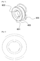
- FIG. 1 is a combinational perspective view of an implant structure according to a preferred embodiment of the present invention
- FIG. 2 is an exploded perspective view of the implant structure of FIG. 1
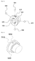
- FIG. 3 is a drawing for illustrating a combinational structure of a housing 400, a ring spring 500 and a number of balls
- FIG. 4 is a state drawing in which a rotation prevention ball 604 is seated on a ball contact surface 512 of the ring spring
- FIG. 5 is a state drawing in which a cap 300 and the housing 400 are combined
- FIG. 6 is a front view viewed from the front of FIG. 5
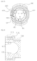
- FIG. 7 is a sectional view for illustrating the structure and the function of the number of balls in the state of FIG. 5
- FIG. 8 is a side elevation view of FIG. 5 .
- FIGs. 1 and 2 since a fixture which is a support which is buried in the mandible corresponding to a lower jaw of a patient in the present invention is a publicly known technology, it is not shown.
- a screw 216 portion of an abutment 200 of FIG. 2 can be combined to a female screw portion of the fixture not shown or that the screw portion itself can replace the role of the fixture by forming the screw 216 portion to be long.
- the present invention largely comprises an abutment 200, a housing 400 combined to an upper head 210 of the abutment, a ring spring 500 mounted at the peripheral surface of the housing, and a cap 300 combined to one side of the housing 400 while covering the ring spring.
- the abutment 200 is formed with an abutment body 214 which is formed with a screw 216 at its lower part and is formed in a circular column shape having the width which is gradually increased going from the screw position to the other side, and a head 210 formed in ball shape at the distal end of the abutment.
- the portion just below the head 210 is formed with a concave 212 of a curved surface having the width narrower than the head 210.
- the head 210 is accommodated in the housing 400.
- a head accommodation section 440 ( FIG. 3 ) which is a space acting a role of a socket for accommodating the head 210 of the ball shape.
- At the side of the housing 400 are formed at least three ball accommodation holes 450 which are formed to communicate with the outside.
- Each head fixing ball 601, 602, 603 corresponding to each of the ball accommodation holes 450 is positioned at the ball accommodation holes, and the diameter of the ball is formed to be larger than the ball accommodation holes 450, and at the ball accommodation hole 450 position is possible a partial displacement of the balls moving into and out of the head accommodation section 440. It is preferable that the number of the head fixing balls 601, 602, 603 is three or more.
- These head fixing balls 601, 602, 603 are pushed by the head 210 so as to be displaced when the head 210 is drawn into the head accommodation section 440 ( FIG. 3 ).
- T1, T2, T3 represent directions in which the head 210 contacts the head fixing balls 601, 602, 603 and pushes the three balls.
- the head 210 is not shown for conveniences.
- a ring spring 500 is inserted at a portion of the housing 400 where the ball accommodation holes 450 are formed, so as to block the ball accommodation holes 450.
- FIG. 3 shows a state of combination the housing 400 and the ring spring 500.
- the ring spring 500 is formed in a ring shape, however, a part thereof is cut out.
- the ring spring is cut in a form of a circle at the inner side of separation section 514, 515 where one side of the ring spring is cut, and at the middle thereof is formed a void space referred to as a ring spring space section 510. And, at the periphery of the ring spring space section 510, a ball contact surface 512 of curved surface where the rotation prevention ball 604 can be seated is formed.
- the housing 400 and the ring spring are combined so that a ball accommodating recess 480 formed at a side of the housing 400 and the ball contact surface 512 of the ring spring correspond to each other.
- FIG. 4 shows a state of the combination of FIG. 3 viewed at another angle.
- the cap 300 covers the ring spring 500 in the state of FIG. 3 and is a portion acting a role of a lid finally combined to the housing 400.
- the longitudinal size and the transverse size of one distal end of the cap are respectively represented as a, b, and the b portion is formed to be small to correspond to the narrow teethridge width of the patient by making the b portion smaller than the a portion.
- the housing 400 and the cap 300 are combined to be in a position to act a role of an outer housing, and the ring spring 500 is inserted in them.
- the head fixing balls 601, 602, 603 are displaced in the direction of T1, T2, T3, and at this time, the ring spring receives the force from the three balls 601, 602, 603 so that the separation sections 514, 515 which are the cut portions of the ring spring are wide opened.
- the head 210 is pushed into the housing 400 so as to be combined, the wide opened ring spring is again restored, the three balls 601, 602, 603 are again restored to their original positions in the direction opposite to the T1, T2, T3, and the concave section 212 ( FIG. 2 ) which is a portion proximate to the head and the three head fixing balls 601, 602, 603 mutually contact.
- the rotation prevention ball 604 is seated at the ball contact surface 512 ( FIG. 3 ) of the ring spring 500 and at the same time one side of the rotation prevention ball 604 maintains the state of being inserted in the ball accommodating recess 480 of the housing 400.
- This rotation prevention ball 604 plays the role of preventing the ring spring 500 from being rotated while the ring spring 500 is in the state of FIG. 8 . That is, since the ring spring 500 exists in the intermediate space formed by combination of the cap 300 and the housing 400, a device for preventing the ring spring from rotating in the direction of R1 or R2 ( FIG. 7 ) is necessary, however, here the structural instability of the implant structure can be removed by stably fixing the ring spring by the rotation prevention ball 604.
- the present invention is characterized in that the ball and socket structure is applied to the combination of the abutment and the housing which accommodates the abutment.
- the head accommodation section 440 takes charge of the role of the socket, and the positions of the head 210 and the ring spring 500 are stably hold by the number of balls 601, 602, 603, 604.
- the upper part of the abutment is not in the form of sphere.
- the implant structure can be installed in a direction which is not a direction parallel to the fixture buried inclined, that is, in a direction parallel to the movement of the jaw through the ball and socket structure of the upper side of the abutment regardless of the inclined fixture, so that the problems of the conventional implant structure as described above can be solved.
- the present invention relates to a structure for improving the matching of the implant by using the ball and socket structure and can be used usefully in the dental implant field.
Landscapes
- Health & Medical Sciences (AREA)
- Oral & Maxillofacial Surgery (AREA)
- Dentistry (AREA)
- Epidemiology (AREA)
- Life Sciences & Earth Sciences (AREA)
- Animal Behavior & Ethology (AREA)
- General Health & Medical Sciences (AREA)
- Public Health (AREA)
- Veterinary Medicine (AREA)
- Orthopedic Medicine & Surgery (AREA)
- Dental Prosthetics (AREA)
Applications Claiming Priority (2)
| Application Number | Priority Date | Filing Date | Title |
|---|---|---|---|
| KR1020130142146A KR101386560B1 (ko) | 2013-11-21 | 2013-11-21 | 치과용 임플란트 구조물 |
| PCT/KR2014/010937 WO2015076530A1 (ko) | 2013-11-21 | 2014-11-14 | 치과용 임플란트 구조물 |
Publications (2)
| Publication Number | Publication Date |
|---|---|
| EP3085329A1 true EP3085329A1 (de) | 2016-10-26 |
| EP3085329A4 EP3085329A4 (de) | 2017-11-08 |
Family
ID=50658021
Family Applications (1)
| Application Number | Title | Priority Date | Filing Date |
|---|---|---|---|
| EP14864584.9A Withdrawn EP3085329A4 (de) | 2013-11-21 | 2014-11-14 | Zahnimplantatstruktur |
Country Status (5)
| Country | Link |
|---|---|
| US (1) | US11191621B2 (de) |
| EP (1) | EP3085329A4 (de) |
| KR (1) | KR101386560B1 (de) |
| CN (1) | CN105916466B (de) |
| WO (1) | WO2015076530A1 (de) |
Cited By (1)
| Publication number | Priority date | Publication date | Assignee | Title |
|---|---|---|---|---|
| KR102339789B1 (ko) * | 2021-08-24 | 2021-12-14 | 채희진 | 틀니 착탈 고정체 겸용 착탈가능한 임플란트 결합 보철물 |
Families Citing this family (18)
| Publication number | Priority date | Publication date | Assignee | Title |
|---|---|---|---|---|
| WO2016143978A2 (ko) * | 2015-03-10 | 2016-09-15 | (주)카이노스메덴텍 | 오버덴쳐용 볼 타입 어태치먼트 장치 및 볼 타입 어태치먼트가 적용된 오버덴쳐의 제작방법 |
| KR101625167B1 (ko) | 2015-09-17 | 2016-05-27 | (주)카이노스메덴텍 | 오버덴처용 볼 타입 어태치먼트 장치 |
| KR101669612B1 (ko) * | 2015-10-15 | 2016-11-09 | 오스템임플란트 주식회사 | 치과용 구조물의 부착장치 |
| KR101633258B1 (ko) * | 2016-01-21 | 2016-06-27 | 채희진 | 시술 및 보정이 용이한 임플란트 결합보철물 |
| KR101633259B1 (ko) * | 2016-02-25 | 2016-06-24 | 채희진 | 착탈이 가능한 임플란트 결합보철물 |
| KR101911081B1 (ko) * | 2016-12-07 | 2018-10-23 | 박지훈 | 치과용 임플란트 |
| KR101981778B1 (ko) * | 2017-06-26 | 2019-05-23 | 오해수 | 어뷰트먼트 및 이를 포함하는 임플란트 |
| KR102036605B1 (ko) * | 2017-07-31 | 2019-10-25 | (주) 예스바이오테크 | 픽스쳐체결용 틀니고정장치 |
| KR101840672B1 (ko) * | 2017-11-10 | 2018-03-21 | 윤장훈 | 인조치아 고정장치 |
| CN108524028B (zh) * | 2018-05-04 | 2019-08-16 | 冯萍 | 一种牙科种植结构 |
| AU2019281042B2 (en) * | 2018-06-04 | 2024-06-13 | Implant Protesis Dental 2004 S.L. | Assembly for forming an abutment for a dental implant with an unpredetermined length |
| KR101966407B1 (ko) | 2018-11-21 | 2019-04-05 | 주식회사 하이니스 | 어버트먼트 조립체 |
| KR102107991B1 (ko) * | 2019-10-18 | 2020-05-07 | 채희진 | 틀니체결용 임플란트 및 이를 이용한 틀니 제조방법 |
| KR102105919B1 (ko) * | 2020-02-11 | 2020-04-29 | 부산대학교 산학협력단 | 반복적으로 교체가 가능한 틀니착탈부재를 포함하는 무치악 환자용 틀니 및 이의 제조방법 |
| CN112773531A (zh) * | 2021-01-26 | 2021-05-11 | 广州市健齿生物科技有限公司 | 牙种植体组件 |
| KR102604677B1 (ko) | 2021-05-25 | 2023-11-24 | 부산대학교 산학협력단 | 이중 유지 구조를 갖는 치과용 임플란트 구조물 및 치과용 임플란트 구조물을 제조하기 위한 디지털 보철 시스템 |
| US12303352B2 (en) | 2021-06-03 | 2025-05-20 | Full Arch Solutions, Llc | Omni-directional multi-unit abutment dental systems |
| JP7630017B2 (ja) | 2021-06-03 | 2025-02-14 | フル アーチ ソリューションズ, エルエルシー | スクリュ装着式歯科補綴物の為の全方向マルチユニットアバットメントシステム |
Family Cites Families (17)
| Publication number | Priority date | Publication date | Assignee | Title |
|---|---|---|---|---|
| US3514858A (en) * | 1969-04-14 | 1970-06-02 | Ralph H Silverman | Denture securing apparatus |
| US4932868A (en) * | 1986-09-04 | 1990-06-12 | Vent-Plant Corporation | Submergible screw-type dental implant and method of utilization |
| US5049072A (en) * | 1990-06-26 | 1991-09-17 | Calcitek, Inc. | O-ring attachment system for dental prosthesis |
| DE19633570C1 (de) * | 1996-08-21 | 1998-01-02 | Imz Fertigung Vertrieb | Enossales Einzelzahnimplantat mit Verdrehsicherung und Stanzwerkzeug sowie Positionierhilfe zur Fertigstellung eines solchen Einzelzahnimplantats |
| IT1294936B1 (it) * | 1997-07-16 | 1999-04-23 | Denni Rondini | Dispositivo di ancoraggio per una protesi mobile |
| US5871357A (en) * | 1998-04-15 | 1999-02-16 | Tseng; Hsien-Jung | Fixing device for a removable denture |
| US7066736B2 (en) * | 2002-09-12 | 2006-06-27 | Zimmer Dental, Inc. | Dental impression coping with retention |
| US7704076B2 (en) * | 2006-12-20 | 2010-04-27 | Zest Ip Holdings Llc | Dental attachment assembly and method |
| KR100884614B1 (ko) * | 2007-05-28 | 2009-02-23 | 이규호 | 치과용 임플란트 |
| KR100985533B1 (ko) * | 2008-11-10 | 2010-10-05 | 주식회사 디오 | 덴탈용 드릴연장장치 |
| US20100291507A1 (en) * | 2009-05-13 | 2010-11-18 | Custom Spine, Inc. | Polyaxial Dental Implant |
| ES2496178T3 (es) * | 2009-08-20 | 2014-09-18 | Biedermann Technologies Gmbh & Co. Kg | Dispositivo de anclaje de hueso |
| JP5514972B2 (ja) * | 2009-12-10 | 2014-06-04 | 株式会社ナントー精密 | インプラント |
| KR101065924B1 (ko) * | 2011-03-09 | 2011-09-19 | 박영일 | 지대부의 각도조절이 가능한 치과용 임플런트 |
| ES2688592T3 (es) * | 2011-06-08 | 2018-11-05 | Zest Ip Holdings, Llc | Dispositivo de fijación dental extraíble |
| ES2386589B2 (es) * | 2012-04-02 | 2013-03-25 | Terrats Mecanizados, S.L. | Aditamento protésico |
| KR101633259B1 (ko) * | 2016-02-25 | 2016-06-24 | 채희진 | 착탈이 가능한 임플란트 결합보철물 |
-
2013
- 2013-11-21 KR KR1020130142146A patent/KR101386560B1/ko not_active Expired - Fee Related
-
2014
- 2014-11-14 EP EP14864584.9A patent/EP3085329A4/de not_active Withdrawn
- 2014-11-14 WO PCT/KR2014/010937 patent/WO2015076530A1/ko not_active Ceased
- 2014-11-14 US US15/038,459 patent/US11191621B2/en not_active Expired - Fee Related
- 2014-11-14 CN CN201480063655.1A patent/CN105916466B/zh not_active Expired - Fee Related
Cited By (1)
| Publication number | Priority date | Publication date | Assignee | Title |
|---|---|---|---|---|
| KR102339789B1 (ko) * | 2021-08-24 | 2021-12-14 | 채희진 | 틀니 착탈 고정체 겸용 착탈가능한 임플란트 결합 보철물 |
Also Published As
| Publication number | Publication date |
|---|---|
| US11191621B2 (en) | 2021-12-07 |
| EP3085329A4 (de) | 2017-11-08 |
| US20160287357A1 (en) | 2016-10-06 |
| WO2015076530A1 (ko) | 2015-05-28 |
| CN105916466B (zh) | 2018-11-27 |
| CN105916466A (zh) | 2016-08-31 |
| KR101386560B1 (ko) | 2014-04-17 |
Similar Documents
| Publication | Publication Date | Title |
|---|---|---|
| US11191621B2 (en) | Dental implant structure | |
| US11638632B2 (en) | Dental implant | |
| AU2015255272B2 (en) | Dental attachment assembly cap and method of use | |
| ES2294811T3 (es) | Dispositivo de instalacion de un implante. | |
| ES2986016T3 (es) | Implante dental | |
| ES2870992T3 (es) | Sistema de restauración dental | |
| KR101417980B1 (ko) | 임플란트용 스캔 바디와 임플란트 어셈블리 | |
| TWI563984B (zh) | Artificial implants used in artificial implants and artificial implants | |
| CN106061430B (zh) | 义齿固定用辅助装置 | |
| EP3585300B1 (de) | Dentaltechnik-kit | |
| ES2676032T3 (es) | Dispositivos para la unión de una construcción de prótesis dental con una mandíbula | |
| KR200470574Y1 (ko) | 오버덴쳐용 볼 타입 어태치먼트 장치 | |
| KR101360952B1 (ko) | 임플란트용 보조장치, 임플란트용 보조기구 및 보관용기 | |
| ES2541027T3 (es) | Implante dental | |
| US8926326B2 (en) | Denture retention system | |
| KR20180128691A (ko) | 치아 발치용 포셉 | |
| KR20140105098A (ko) | 경사형 임플란트 | |
| KR101994119B1 (ko) | 임플란트용 교합측정기 | |
| KR101745575B1 (ko) | 임플란트용 스캔바디의 기능을 구비한 임프레션 캡 | |
| KR101625167B1 (ko) | 오버덴처용 볼 타입 어태치먼트 장치 | |
| KR102292489B1 (ko) | 어버트먼트 홀더 | |
| KR200428099Y1 (ko) | 인공치아 시술용 픽스츄어드라이버 | |
| KR102289208B1 (ko) | 탈착형 치근을 갖는 자연치아 형상의 임플란트 장치 | |
| KR102682745B1 (ko) | 치과용 드라이버 장치 | |
| KR101169450B1 (ko) | 치과 임플란트 시술용 가이드 블록, 치과 임플란트 시술용 가이드 블록 조립체 및 이를 구비한 임플란트 시술용 키트 |
Legal Events
| Date | Code | Title | Description |
|---|---|---|---|
| PUAI | Public reference made under article 153(3) epc to a published international application that has entered the european phase |
Free format text: ORIGINAL CODE: 0009012 |
|
| 17P | Request for examination filed |
Effective date: 20160721 |
|
| AK | Designated contracting states |
Kind code of ref document: A1 Designated state(s): AL AT BE BG CH CY CZ DE DK EE ES FI FR GB GR HR HU IE IS IT LI LT LU LV MC MK MT NL NO PL PT RO RS SE SI SK SM TR |
|
| AX | Request for extension of the european patent |
Extension state: BA ME |
|
| DAX | Request for extension of the european patent (deleted) | ||
| A4 | Supplementary search report drawn up and despatched |
Effective date: 20171006 |
|
| RIC1 | Information provided on ipc code assigned before grant |
Ipc: A61C 13/265 20060101ALI20170929BHEP Ipc: A61C 13/277 20060101ALI20170929BHEP Ipc: A61C 8/00 20060101AFI20170929BHEP |
|
| STAA | Information on the status of an ep patent application or granted ep patent |
Free format text: STATUS: THE APPLICATION IS DEEMED TO BE WITHDRAWN |
|
| 18D | Application deemed to be withdrawn |
Effective date: 20180504 |