EP3085444A1 - Mikrofluidvorrichtung zur fliesskontrolle eines fluids - Google Patents
Mikrofluidvorrichtung zur fliesskontrolle eines fluids Download PDFInfo
- Publication number
- EP3085444A1 EP3085444A1 EP16166022.0A EP16166022A EP3085444A1 EP 3085444 A1 EP3085444 A1 EP 3085444A1 EP 16166022 A EP16166022 A EP 16166022A EP 3085444 A1 EP3085444 A1 EP 3085444A1
- Authority
- EP
- European Patent Office
- Prior art keywords
- microfluidic
- chamber
- membrane
- fluid
- chambers
- Prior art date
- Legal status (The legal status is an assumption and is not a legal conclusion. Google has not performed a legal analysis and makes no representation as to the accuracy of the status listed.)
- Granted
Links
Images


Classifications
-
- B—PERFORMING OPERATIONS; TRANSPORTING
- B01—PHYSICAL OR CHEMICAL PROCESSES OR APPARATUS IN GENERAL
- B01L—CHEMICAL OR PHYSICAL LABORATORY APPARATUS FOR GENERAL USE
- B01L3/00—Containers or dishes for laboratory use, e.g. laboratory glassware; Droppers
- B01L3/50—Containers for the purpose of retaining a material to be analysed, e.g. test tubes
- B01L3/502—Containers for the purpose of retaining a material to be analysed, e.g. test tubes with fluid transport, e.g. in multi-compartment structures
- B01L3/5027—Containers for the purpose of retaining a material to be analysed, e.g. test tubes with fluid transport, e.g. in multi-compartment structures by integrated microfluidic structures, i.e. dimensions of channels and chambers are such that surface tension forces are important, e.g. lab-on-a-chip
- B01L3/502738—Containers for the purpose of retaining a material to be analysed, e.g. test tubes with fluid transport, e.g. in multi-compartment structures by integrated microfluidic structures, i.e. dimensions of channels and chambers are such that surface tension forces are important, e.g. lab-on-a-chip characterised by integrated valves
-
- B—PERFORMING OPERATIONS; TRANSPORTING
- B01—PHYSICAL OR CHEMICAL PROCESSES OR APPARATUS IN GENERAL
- B01L—CHEMICAL OR PHYSICAL LABORATORY APPARATUS FOR GENERAL USE
- B01L2300/00—Additional constructional details
- B01L2300/08—Geometry, shape and general structure
- B01L2300/0809—Geometry, shape and general structure rectangular shaped
- B01L2300/0816—Cards, e.g. flat sample carriers usually with flow in two horizontal directions
-
- B—PERFORMING OPERATIONS; TRANSPORTING
- B01—PHYSICAL OR CHEMICAL PROCESSES OR APPARATUS IN GENERAL
- B01L—CHEMICAL OR PHYSICAL LABORATORY APPARATUS FOR GENERAL USE
- B01L2300/00—Additional constructional details
- B01L2300/08—Geometry, shape and general structure
- B01L2300/0861—Configuration of multiple channels and/or chambers in a single devices
- B01L2300/0864—Configuration of multiple channels and/or chambers in a single devices comprising only one inlet and multiple receiving wells, e.g. for separation, splitting
-
- B—PERFORMING OPERATIONS; TRANSPORTING
- B01—PHYSICAL OR CHEMICAL PROCESSES OR APPARATUS IN GENERAL
- B01L—CHEMICAL OR PHYSICAL LABORATORY APPARATUS FOR GENERAL USE
- B01L2300/00—Additional constructional details
- B01L2300/08—Geometry, shape and general structure
- B01L2300/0861—Configuration of multiple channels and/or chambers in a single devices
- B01L2300/0867—Multiple inlets and one sample wells, e.g. mixing, dilution
-
- B—PERFORMING OPERATIONS; TRANSPORTING
- B01—PHYSICAL OR CHEMICAL PROCESSES OR APPARATUS IN GENERAL
- B01L—CHEMICAL OR PHYSICAL LABORATORY APPARATUS FOR GENERAL USE
- B01L2300/00—Additional constructional details
- B01L2300/08—Geometry, shape and general structure
- B01L2300/0861—Configuration of multiple channels and/or chambers in a single devices
- B01L2300/087—Multiple sequential chambers
-
- B—PERFORMING OPERATIONS; TRANSPORTING
- B01—PHYSICAL OR CHEMICAL PROCESSES OR APPARATUS IN GENERAL
- B01L—CHEMICAL OR PHYSICAL LABORATORY APPARATUS FOR GENERAL USE
- B01L2300/00—Additional constructional details
- B01L2300/08—Geometry, shape and general structure
- B01L2300/0887—Laminated structure
-
- B—PERFORMING OPERATIONS; TRANSPORTING
- B01—PHYSICAL OR CHEMICAL PROCESSES OR APPARATUS IN GENERAL
- B01L—CHEMICAL OR PHYSICAL LABORATORY APPARATUS FOR GENERAL USE
- B01L2300/00—Additional constructional details
- B01L2300/12—Specific details about materials
- B01L2300/123—Flexible; Elastomeric
-
- B—PERFORMING OPERATIONS; TRANSPORTING
- B01—PHYSICAL OR CHEMICAL PROCESSES OR APPARATUS IN GENERAL
- B01L—CHEMICAL OR PHYSICAL LABORATORY APPARATUS FOR GENERAL USE
- B01L2400/00—Moving or stopping fluids
- B01L2400/04—Moving fluids with specific forces or mechanical means
- B01L2400/0475—Moving fluids with specific forces or mechanical means specific mechanical means and fluid pressure
- B01L2400/0481—Moving fluids with specific forces or mechanical means specific mechanical means and fluid pressure squeezing of channels or chambers
-
- B—PERFORMING OPERATIONS; TRANSPORTING
- B01—PHYSICAL OR CHEMICAL PROCESSES OR APPARATUS IN GENERAL
- B01L—CHEMICAL OR PHYSICAL LABORATORY APPARATUS FOR GENERAL USE
- B01L2400/00—Moving or stopping fluids
- B01L2400/04—Moving fluids with specific forces or mechanical means
- B01L2400/0475—Moving fluids with specific forces or mechanical means specific mechanical means and fluid pressure
- B01L2400/0487—Moving fluids with specific forces or mechanical means specific mechanical means and fluid pressure fluid pressure, pneumatics
-
- B—PERFORMING OPERATIONS; TRANSPORTING
- B01—PHYSICAL OR CHEMICAL PROCESSES OR APPARATUS IN GENERAL
- B01L—CHEMICAL OR PHYSICAL LABORATORY APPARATUS FOR GENERAL USE
- B01L2400/00—Moving or stopping fluids
- B01L2400/06—Valves, specific forms thereof
- B01L2400/0633—Valves, specific forms thereof with moving parts
- B01L2400/0655—Valves, specific forms thereof with moving parts pinch valves
Definitions
- the present invention relates to microfluidic devices of the biochip type, and more particularly, to a microfluidic device for controlling and sequencing a plurality of fluid flow stages and to an analysis method implemented by such a device.
- the invention has applications in many fields, such as among others the fields of medical research, biology and pharmaceuticals.
- a microfluidic device that can chain several stages of flow of a fluid is known in the field of microsystems for medical or chemical analysis.
- the patent application FR 2897282 discloses a method of controlling the advance of a liquid in a microfluidic component comprising a plurality of reaction zones as well as a plurality of passive valves operating capillary forces for blocking the fluid between the reaction zones.
- the control of the advance of the liquid is carried out by the control of the pressure upstream and downstream of the component.
- a pressure pulse can unlock a valve and allow the advance of the liquid.
- the success of the blocking / unblocking is dependent on the wetting properties of the walls with the liquid used. More precisely, the parameters such as the geometries of the valves and the reaction zones, the surface states or the wetting properties must be finely determined, which complicates the realization of the device. In particular, the addition or removal of wetting agent required for a given biological protocol may be incompatible with the basic principle of the blocking valves.
- the object of the present invention is, therefore, to overcome the aforementioned drawbacks by proposing a microfluidic device for controlling the flow of a fluid perfectly adapted to a chemical or biological protocol and very simple to achieve.
- the microfluidic chambers themselves allow to move a fluid in a sequence of well controlled operations without resorting to subsidiary valves or pumps and without depending on the state of the surfaces or wetting properties of the walls of said chambers .
- this device makes it possible to have a large number of reaction chambers with identical volumes that are well calibrated. requiring no means of measurement while minimizing dead volumes. This makes it possible to easily and accurately transport calibrated volume (s) of fluid (s) in order to integrate a fluidic protocol.
- This device is very simple to build and use while being very accurate.
- the deformable membrane has a dual function, namely a valve and pump function.
- At least one of the microfluidic chambers contains an embedded reagent (preferably dried or freeze-dried) adapted to react with the fluid of interest.
- an embedded reagent preferably dried or freeze-dried
- the fluid of interest mixes with the reagent (s) which is (are) already present in the device making it possible in a simple manner to carry out a chemical or biological analysis protocol. many stages.
- the volume of a microfluidic communication channel is about ten times smaller than the volume of a cavity. This makes it possible to minimize the appearance of air bubbles and to avoid dilution of the mixture (fluid and onboard reagents) during transport from room to room.
- the microfluidic network comprises an inlet orifice (or reservoir) formed in the first substrate and connected to an inlet of said at least one series of microfluidic communication channels, said orifice being adapted to receive the fluid of interest.
- an inlet orifice or reservoir
- the orifice being adapted to receive the fluid of interest.
- the microfluidic network comprises an outlet orifice (or reservoir) formed in the first substrate or the second substrate and connected to an output of said at least one series of microfluidic communication channels.
- the mixture can be easily recovered or evacuated.
- the first substrate, the membrane and the second substrate are assembled so as to ensure a tight contact between the membrane and the first and second surfaces of the first and second substrates while providing a space of flow at cavities and microfluidic communication channels.
- the assembly is carried out by gluing, by plasma, or by mechanical plating.
- the assembly can be achieved by different methods with or without glue or by a simple mechanical plating that can be provided by a flange system.
- the device comprises an actuating mechanism adapted to act on the membrane at each microfluidic chamber in order to switch the state of the selected microfluidic chamber.
- the actuating mechanism is selected from the following mechanisms: pneumatic, mechanical, electrostatic, piezoelectric, and magnetic.
- the actuating mechanism is a pneumatic mechanism adapted to deform the membrane by exerting pressure via actuating holes formed in the second substrate and opening at the levels of the microfluidic chambers, the change of state of any microfluidic chamber being effected by a modification of the pressure value exerted on the membrane via the actuating hole corresponding to said microfluidic chamber.
- said at least one series of cavities and said at least one series of microfluidic communication channels are formed on the first microfluidic surface, a microfluidic chamber being in an open state when the deformable membrane is tackled on the second microfluidic surface so that the membrane and the corresponding cavity delimit a reservoir of predetermined volume equal to that of the cavity thus allowing the flow of the fluid of interest into said reservoir, and a microfluidic chamber being in a closed state when the membrane is plated on the first microfluidic surface while conforming to the shape of the corresponding cavity so that the volume between the membrane and the cavity is virtually zero thus blocking the flow of the fluid of interest through said chamber.
- the cavities and the communication channels are advantageously machined on the same substrate and the deformation of the membrane makes it possible to create microfluidic chambers while pumping the fluid of interest from chamber to chamber.
- said at least one series of cavities is formed on the second microfluidic surface and said at least one sequence of microfluidic communication channels is formed on the first microfluidic surface
- a microfluidic chamber being an open state when the membrane is plated on the second microfluidic surface while conforming to the shape of the corresponding cavity so that the membrane and the first microfluidic surface delimit a reservoir of predetermined volume equal to that of the cavity thus allowing the flow of the fluid of interest in said reservoir
- a microfluidic chamber being in a closed state when the membrane is plated on the first microfluidic surface so that the volume between the membrane and the first surface is virtually zero thereby preventing the flow of fluid from interest through said chamber.
- the cavities and the communication channels are machined on different substrates.
- the first substrate and / or the second substrate are made of a transparent material.
- the cavities have a spherical cap shape whose base has a diameter between about 1 mm and 1 cm and whose height is between about 100 microns and 1 mm.
- reaction volumes of a few microliters (100nl to 100 .mu.l).
- each channel of said at least one suite of microfluidic communication channels has a length between about 1 mm and 5 mm and a section between about 50 microns and 500 microns side.
- each microfluidic channel is at most ten times smaller than that of a microfluidic chamber.
- each of said first and second substrates has a thickness between about 200 microns and 4 mm and a surface of the order of several square centimeters.
- the material of the first substrate and / or the second substrate is selected from the following materials: polycarbonate polymer, PMMA, COC, silicon, and paper.
- the microfluidic network comprises a set of microfluidic branches connected to the same input port and each comprising a series of microfluidic communication channels connecting sequentially a corresponding sequence of microfluidic chambers.
- the branches are arranged in comb or star from said inlet port.
- the liquid is mixed with the reagents making, for example, a multi-step biological analysis protocol.
- the process comprises stirring steps by flipping the liquid between two microfluidic chambers a specified number of times.
- the method comprises a step of optical measurement (fluorescence or colorimetric) of the liquid (reaction) in at least one (last) detection chamber.
- the concept underlying the invention consists in controlling the flow of a fluid through a series of tanks without using valves and without resorting to capillary forces.
- the Fig. 1 illustrates very schematically a microfluidic device for controlling the flow of a fluid of interest, according to the invention.
- the microfluidic device 1 comprises a microfluidic network 3 comprising at least one series of microfluidic chambers 5 interconnected sequentially.
- the microfluidic chambers 5 are able to be deformed in a retracted or deployed manner. More particularly, each microfluidic chamber 5 is switchable between a first closed state preventing or blocking the flow of the fluid of interest through the chamber 5 and a second open state allocating to the chamber in the open state a predetermined volume while pumping. (aspirant) the fluid of interest in this chamber.
- the open state thus allows the flow of the fluid of interest while calibrating the volume of the chamber. More particularly, the volume of each chamber 5 is adjustable or inflatable between an almost zero volume and a calibrated or non-zero predetermined volume.
- the chamber 5 When the chamber 5 is in a closed state, its volume is zero and therefore, the advance of the fluid is blocked.
- the chamber when the chamber is in an open state, its volume is calibrated and the fluid can flow to fill the chamber.
- the action of switching the state of a chamber from a closed state to an open state allows the fluid to be pumped into this chamber.
- the successive actuation of the microfluidic chambers 5 between a closed state and an open state makes it possible to move a reaction volume from chamber to chamber without using auxiliary valves and without resorting to pumps or capillary forces.
- the volumes of the different chambers 5 in the open state are identical.
- the volume of a chamber 5 in the open state is of the order of a few hundred nanoliters to a few hundred microliters.
- the microfluidic device 1 also comprises a reservoir or inlet orifice 7 adapted to receive a sample of a fluid of interest.
- the inlet orifice 7 is connected to an inlet of the microfluidic network and more particularly to a first chamber of the suite of microfluidic chambers 5.
- a single chamber suite is shown in FIG. Fig. 1 but of course, the microfluidic device may comprise a plurality of chamber suites (see Figs. 9A and 9B ) and possibly a plurality of inlet ports.
- the microfluidic device 1 can be used to perform a chemical or biological analysis on a sample of a fluid of interest consisting for example of a biological fluid.
- reagents can be embedded in dried form in at least one of the microfluidic chambers 5.
- the fluid of interest placed in the inlet port 7 mixes with the reagents for the purpose of perform a multi-step analysis protocol.
- the Fig. 2 illustrates very schematically a microfluidic device for controlling the flow of a fluid of interest, according to one embodiment of the invention.
- the microfluidic device 1 comprises two substrates 11, 13 and a deformable membrane 15 disposed between the two substrates.
- the first substrate 11 comprises a first microfluidic surface 111 and the second substrate 13 comprises a second microfluidic surface 131.
- the first and second surfaces 111, 131 are parallel to each other and separated from each other by the deformable membrane 15.
- first and second surfaces 111, 131 may be of rectangular or circular shape or any other shape.
- Each of the first 11 and second 13 substrates has a thickness in the Z direction between about 200 ⁇ m and 4 mm and a surface (ie, area of the first or second microfluidic surface in a (X, Y) plane) of order of several square centimeters, typically a surface equivalent to a microscope slide or a credit card.
- the deformable membrane has a thickness (in the Z direction) of the order of one hundred microns (10 ⁇ m to 1 mm), for example 300 ⁇ m.
- the material of the first substrate 11 and / or the second substrate 13 is selected from the following materials: polycarbonate polymer, PMMA, COC, silicon, and paper.
- the membrane 15 is formed of a highly deformable material such as an elastomer of the silicone family (example PDMS polydimethylsiloxane, Ecoflex ®).
- At least one series of cavities 51 is formed on one or the other of the first and second microfluidic surfaces 111, 131.
- the Fig. 3 shows that the cavities 51 are formed on the first microfluidic surface 111 of the first substrate 11 and the Fig. 7 shows that the cavities 51 are formed on the second microfluidic surface 131 of the second substrate 13.
- the cavities 51 have a shape of spherical cap whose base has a diameter in a plane (X, Y) between about 1 mm and 1 cm and whose height in the Z direction is between about 100 microns and 1 mm.
- the succession of cavities 51 defines with the deformable membrane 15 the following microfluidic chambers 5.
- the deformable membrane 15 is able to be deformed at each microfluidic chamber 5 to be pressed against a part of the first microfluidic surface 111 or against a part of the second microfluidic surface 131 thus making it possible to switch the state of each microfluidic chamber 5 between the first and second states.
- the membrane is adapted to open or block the passage of the fluid and to pump the fluid from a reservoir or room to at least one other room.
- the microfluidic device 1 comprises an actuating mechanism 21 adapted to act on the membrane 15 at each microfluidic chamber 5 in order to switch the state of the selected microfluidic chamber.
- the actuating mechanism 21 may be of the pneumatic or mechanical type.
- At least one suite of microfluidic communication channels 25 is formed on either one of the first and second microfluidic surfaces 111, 131.
- Each suite of microfluidic communication channels 25 sequentially connects the suite of microfluidic chambers. 5 (here, only one suite of microfluidic communication channels 25 formed on the first surface 111 and a single suite of microfluidic chambers 5 are shown). More particularly, the various channels of the suite of microfluidic communication channels 25 connect in series the different microfluidic chambers 5, each communication channel 25 having a length of between approximately 1 mm and 5 mm and a cross section between approximately 50 ⁇ m and 500 ⁇ m. side.
- the suite of microfluidic communication channels 25 has a smaller volume than that of the series of cavities 51.
- the volume of a microfluidic communication channel 25 is at most ten times smaller than the volume of a microfluidic chamber 5.
- V1 be the volume of a chamber 5 and V2 the volume of a microfluidic communication channel 25.
- the actuation of two consecutive chambers generates a liquid displacement of V1-V2, because the volume V2 remains lost in the channel 25.
- N displacements a fluid volume of N ⁇ V 2 is lost. .
- V2 / V1 ratio it is therefore advantageous to minimize the V2 / V1 ratio in order to minimize the appearance of air bubbles (or at least reduce their volume) or to avoid diluting the reagents / samples transported from room to room. This is all the more advantageous as the number of chambers required for the analysis protocol is large.
- each cavity 51 has a base of 3 mm and a height of 300 ⁇ m defining an open chamber volume of 1.1 ⁇ l, whereas each microfluidic communication channel 25 measures 3 mm * 100 ⁇ m * 300 ⁇ m. represents a volume of 0.1 ⁇ l.
- the microfluidic device 1 has a reservoir or inlet port 7 formed in the first substrate 11 and connected to an inlet 251 of the suite of microfluidic communication channels 25 (i.e. at the first channel of the channel sequence).
- the microfluidic device 1 comprises an orifice or outlet reservoir (not shown) formed in the first substrate 11 or the second substrate 13 and connected to an outlet 253 of the suite of microfluidic communication channels 25 (ie to the last channel of the following channels).
- holes (or channels) for actuating 27 are advantageously formed in the first 11 or second 13 substrate in the direction Z to lead to the levels of the microfluidic chambers 5.
- These actuating holes 27 are used to actuate the deformable membrane 15 by pneumatic or mechanical actuating mechanisms. For example by a suction plating action (suction effect).
- the fluidic network 2 that is to say the inlet orifices 7 and possibly the outlet, the cavities 51, the microfluidic communication channels 25 connecting the cavities 51, and the holes 27 or openings for the pneumatic actuation or mechanical machining are machined according to methods known by the plastics industry such as mechanical machining with a CNC machine, by 3D printing, or preferably by injection.
- the first substrate 11, the membrane 15 and the second substrate 13 are assembled so as to ensure a sealing contact between the membrane 15 and the first and second surfaces 111, 131 of the first and second substrates while providing a flow space at the cavities 51 and microfluidic communication channels 25.
- the assembly can be made by gluing, by plasma, or by mechanical plating.
- a reagent is advantageously deposited in at least one of the microfluidic chambers 5 either on the membrane 15 or on the walls of the cavity 51 before the assembly of the microfluidic device 1.
- at least one of the microfluidic chambers 5 contains embedded reagent in dried or lyophilized form and adapted to react with the fluid of interest.
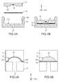
- the Fig. 3 illustrates very schematically a microfluidic device for controlling the flow of a fluid of interest, according to a first preferred embodiment of the invention.
- this figure illustrates a section of the microfluidic device in a plane (Y, Z).
- the cavity continuation (s) 51 (in the form of a spherical cap) and the continuation (s) of microfluidic communication channels 25 are formed on the first microfluidic surface 111 of the first substrate 11. More particularly, each suite of microfluidic communication channels 25 sequentially connects the succession of cavities 51, each channel 25 connecting two consecutive cavities 51. Moreover, the inlet orifice 7 is formed in the first substrate 11.
- Actuating holes 27 are formed in the second substrate 13 opening after assembly of the device 1 facing the cavities 51.
- the deformable membrane 15 is disposed between the first substrate 11 (here corresponding in orientation Z to a plate upper) and the second substrate 13 (corresponding to a lower plate).
- the suite of microfluidic chambers 5 is formed by the deformable membrane 15 and the succession of cavities 51.
- each microfluidic chamber 5 is delimited by a corresponding cavity 51 and a corresponding part of the membrane 15 so that the state (open or closed) of the chamber 5 is defined by the actuation of this corresponding part of the membrane 15.
- the two substrates 11 and 13 can be assembled with the deformable membrane 15 by gluing, the coating of which can be performed by screen printing so as not to locally stick the membrane at the cavities 51 or microfluidic communication channels 25 on the first 11 or second substrates 13.
- An adhesive-free assembly can also be envisaged by exposing the first and second microfluidic surfaces 111, 131 to an oxygen plasma prior to assembly. In this case, it is also possible to perform localized treatment so as not to stick the deformable membrane 15 at the cavities 51 or microfluidic communication channels 25.
- a mechanical plating provided by a flange system (enclosed greenhouse, screws etc ... ) or any known mechanical system (clips, rivets etc ...) to maintain a good contact and a good seal between the membrane 15 and the two substrates 11 and 13 except at the cavities 51 and microfluidic channels 25.
- FIGs. 4A and 4B schematically illustrate an assembly of the microfluidic device by mechanical plating.
- the Fig. 4A illustrates an exploded view before assembly
- Fig. 4B illustrates a view of the microfluidic device after assembly.
- the first substrate 11 (corresponding to an upper plate) comprises the microfluidic communication channels and cavity cavities 51 in the form of a spherical cap. Reagents 31 were dispensed and dried on the walls of the cavities 51.
- the second substrate 13 (corresponding to a lower plate) has actuating holes 27 and lugs 135.
- the number of lugs depends on the surface of the microfluidic device 1.
- the assembly is carried out simply by putting into contact the first substrate 11 and the deformable membrane 15 on the second substrate 13 and the holding is obtained by the lugs 135.
- the lower face of the deformable membrane 15 is in contact with the second surface 131 of the second substrate 13 (lower cover) and the face upper deformable membrane 15 is in contact with the first surface 111 of the first substrate 111 (top cover).
- ten or so pins will be placed distributed around the device to properly distribute the plating force.
- the Figs. 5A and 5B schematically illustrate the states of a microfluidic chamber according to the embodiment of the Fig. 3 .
- the Fig. 5A illustrates a view of a section (Y, Z) of a microfluidic chamber 5 in a closed state where the corresponding portion of the membrane is in a retracted form.
- the portion of the membrane 15 corresponding to the chamber 5 is plated on a portion of the first microfluidic surface 111 of the upper plate 11 while perfectly matching the shape of the corresponding cavity 51 so that the volume between the membrane 15 and the cavity 51 is virtually zero thus blocking the flow of the fluid of interest through the chamber 5.
- the cavity 51 has the shape of a spherical cap and the membrane 15 locally complies with the shape of the spherical cap 51 thus closing the access to the microfluidic chamber 5.
- the Fig. 5B illustrates a view of a microfluidic chamber 5 in an open state where the corresponding portion of the deformable membrane 15 is put into an expanded form. Indeed, according to this state, the portion of the membrane corresponding to the chamber 5 is plated on a portion of the second microfluidic surface 131 of the lower plate 13 so that the membrane 15 and the corresponding cavity 51 delimit a predetermined volume reservoir. equal to that of the cavity 51 thus allowing the flow of the fluid of interest in the chamber 5.
- the microfluidic device 1 comprises a pneumatic actuation mechanism 21 adapted to act on the deformable membrane 15 at each microfluidic chamber 5 in order to switch the state of the selected microfluidic chamber.
- the pneumatic actuating mechanism 21 is adapted to deform at least a portion of the membrane 15 by exerting a pressure or a pressure pulse by means of a pressure fluid, and in particular a pressure gas via the actuating holes 27 formed in the second substrate 13 and opening at the levels of the microfluidic chambers 5.
- a pressure fluid and in particular a pressure gas
- the change of state of any microfluidic chamber 5 is achieved by a modification of the pressure value exerted locally on the membrane 15 (here under the membrane) via the actuating hole 27 corresponding to the microfluidic chamber 5.
- the pneumatic actuating mechanism 21 comprises an automaton 211 making it possible to program the pressure in each operating hole 27.
- a positive pressure makes it possible to lift (or retract) the deformable membrane 15 at the local level thus closing the microfluidic chamber 5 while a negative pressure ensures the plating of the deformable membrane 15 locally on the second microfluidic surface 131 of the lower plate 13 and thus the opening of the microfluidic chamber 5.
- the return to the open state of the microfluidic chamber 5 can be simply ensured by the stiffness of the membrane 15 if it is sufficiently rigid, and the open state can be obtained with a zero pressure (ie a setting to atmospheric pressure).
- the actuating mechanism 21 may be a mechanical mechanism adapted to deform the deformable membrane 15 by actuating pistons (not shown) via the actuating holes 27 formed in the second substrate 131.
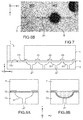
- the Fig. 6A schematically illustrates a method of analysis implemented by means of a microfluidic device according to the invention.
- a sample of a reaction liquid 33 (corresponding to the fluid of interest) is injected into the inlet orifice 7 of the microfluidic device 1.
- the reaction liquid 33 is for example a biological fluid (blood, saliva, urine, etc.) or a chemical fluid that must be analyzed according to a multi-step protocol.
- steps E1-E2 the state of the microfluidic chambers 5 is switched from the closed state to the open state according to a predetermined sequence of operations adapted to control the passage of the reaction liquid 33 between the various microfluidic chambers 5.
- This chamber contains the onboard reagents 31 which are dissolved in contact with the liquid 33.
- This first step makes it possible to carry out the first operation of the biological or chemical protocol by mixing the sample 33 with the first reagent 31.
- Table T1 The succession of states of the process of the Fig. 6A for a four-step protocol performed in four successive microfluidic chambers can be summarized in Table T1 as follows: Table: T1 Step N ° R1 R2 R3 R4 Initial 0 0 0 0 E1 1 0 0 0 E2 0 1 0 0 E3 0 0 1 0 E4 0 0 0 1
- Table T3 makes it possible to define a discrete volume of fluid having a volume perfectly determined by the volume of chamber R1. This volume of samples is transported step by step on the tanks R2 to R4 by the changes of states of different chambers.
- step E24 it is also possible to generate (step E24) then move (step E25) a duplicate with two consecutive tanks placed in state 1. It can also "cut in two the duplicate" (step E26) and then reassemble it (step E27), etc.
- the method comprises stirring steps by flipping the liquid 33 between two microfluidic chambers 5 a given number of times. Indeed, to assist and accelerate the mixing between the sample 33 and the reagents 31 in a chamber 5 of rank "i", it is possible to perform stirring steps by circulating the liquid between the chamber of rank "i" and that rank "i-1".
- Table T5 below explains the reagent mixture between chambers R2 and R3 by flipping the liquid between these two microfluidic chambers for seven operations.
- a dozen tilts makes it possible to well homogenize the reaction mixture by stirring.
- the analysis method includes a final step E4 ( Fig. 6A ) measuring the liquid in at least one detection chamber.
- the result of the analysis protocol can be performed for example by a fluorescence measurement or by colorimetry according to the protocol used. Generally this operation is carried out at the end of the protocol therefore in the last microfluidic chamber 5.
- the first substrate 11 and / or the second substrate 13 and / or the membrane 15 are made of a transparent material thus making it possible to see the content of the microfluidic chambers 5 and to facilitate the optical measurement of the result.
- the Fig. 7 illustrates very schematically a microfluidic device for controlling the flow of a fluid of interest, according to a second preferred embodiment of the invention.
- each series of cavities 51 is formed on the second microfluidic surface 131 of the second substrate 13.
- each suite of microfluidic communication channels 25 is formed on the first microfluidic surface 111 of the first substrate 11.
- the continuity between the different channels of a sequence of microfluidic channels 25 formed on the first substrate 11 is provided by the cavities 51 of the corresponding cavity sequence formed on the second substrate 13.
- the cavities 51 formed on the second microfluidic surface 131 have positions and diameters complementary to the positions and lengths of the channels 25 formed on the first microfluidic surface 111.
- the inlet orifice 7 is formed in the first substrate 11 and the actuating holes 27 are formed in the second substrate 13. It will be noted that here, the actuating holes 27 open into the corresponding cavities 51 .
- the deformable membrane 15 is disposed between the first substrate 11 (here corresponding in Z orientation to an upper plate) and the second substrate 13 (corresponding to a lower plate).
- the suite of microfluidic chambers 5 is formed by the deformable membrane 15 and the series of cavities 51.
- a microfluidic chamber 5 is in an open state when the portion of the corresponding membrane is deformed and is in a closed state when the portion of the corresponding membrane is released.
- FIGs. 8A and 8B schematically illustrate the states of a microfluidic chamber according to the embodiment of the Fig. 7 .
- the Fig. 8A illustrates a view of a microfluidic chamber in a closed state where the corresponding part of the deformable membrane 15 is put into a relaxed form, for example by maintaining an atmospheric pressure via the actuating hole 27 formed in the second substrate 13. in this state, the portion of the membrane 15 corresponding to the chamber 5 is plated on the corresponding portion of the first microfluidic surface 111 (ie on the upper plate) so that the volume between the membrane 15 and this first surface 111 is almost zero blocking the flow of the fluid of interest through the chamber.
- the Fig. 8B illustrates a view of a microfluidic chamber 5 in an open state where the corresponding portion of the membrane is put into a deformed shape.
- the deformation of the membrane 15 at the chamber 5 can be achieved by exerting a negative pressure via the actuating hole 27 formed in the second substrate 13.
- the portion of the membrane 15 corresponding to the chamber 5 is sucked in. to be plated on the corresponding portion of the second microfluidic surface 131 (ie, the lower plate) while conforming to the shape of the corresponding cavity 51 so that the deformed membrane and the corresponding portion of the first microfluidic surface 111 delimit a reservoir of predetermined volume equal to that of the cavity 51 thus allowing the flow of the fluid of interest in this reservoir.
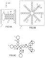
- Figs. 9A, 9B and 9C illustrate very schematically different configurations of a microfluidic device, according to other embodiments of the invention.
- the microfluidic network 3 comprises a set of microfluidic branches 37 connected to the same inlet port 7.
- Each microfluidic branch 37 comprises a series of microfluidic communication channels 25 sequentially connecting a corresponding sequence of microfluidic chambers 5.
- the Fig. 9A shows that the branches 37 are arranged in comb while the Fig. 9B shows that the branches 37 are arranged in a star shape from the inlet orifice 7.
- the Fig. 9C shows an example of a more complex network with intersections or crossings between several fluidic paths. Each intersection makes it possible to perform a mixing operation between different liquids, or to transport different samples or reagents on a part of the microfluidic network. Note that the size of the rooms of the different paths may be different. For example, the arrows on the Figure 9C indicate the possible directions of displacement of the fluidic volumes.
Landscapes
- Chemical & Material Sciences (AREA)
- Health & Medical Sciences (AREA)
- Dispersion Chemistry (AREA)
- Analytical Chemistry (AREA)
- General Health & Medical Sciences (AREA)
- Hematology (AREA)
- Clinical Laboratory Science (AREA)
- Chemical Kinetics & Catalysis (AREA)
- Automatic Analysis And Handling Materials Therefor (AREA)
- Micromachines (AREA)
Applications Claiming Priority (1)
| Application Number | Priority Date | Filing Date | Title |
|---|---|---|---|
| FR1553487A FR3035009B1 (fr) | 2015-04-20 | 2015-04-20 | Dispositif microfluidique de controle d'ecoulement d'un fluide |
Publications (2)
| Publication Number | Publication Date |
|---|---|
| EP3085444A1 true EP3085444A1 (de) | 2016-10-26 |
| EP3085444B1 EP3085444B1 (de) | 2023-03-08 |
Family
ID=53274736
Family Applications (1)
| Application Number | Title | Priority Date | Filing Date |
|---|---|---|---|
| EP16166022.0A Active EP3085444B1 (de) | 2015-04-20 | 2016-04-19 | Mikrofluidvorrichtung zur fliesskontrolle eines fluids |
Country Status (2)
| Country | Link |
|---|---|
| EP (1) | EP3085444B1 (de) |
| FR (1) | FR3035009B1 (de) |
Cited By (7)
| Publication number | Priority date | Publication date | Assignee | Title |
|---|---|---|---|---|
| WO2018091813A1 (fr) | 2016-11-18 | 2018-05-24 | Commissariat à l'énergie atomique et aux énergies alternatives | Procédé et système de commande d'un dispositif microfluidique |
| EP3488929A1 (de) * | 2017-11-28 | 2019-05-29 | Commissariat à l'Énergie Atomique et aux Énergies Alternatives | Injektionsvorrichtung für eine flüssige probe |
| FR3107901A1 (fr) | 2020-03-09 | 2021-09-10 | Commissariat A L'energie Atomique Et Aux Energies Alternatives | Procédé de perfusion micro-fluidique d'un sphéroïde et dispositif adapté pour mettre en œuvre ledit procédé |
| CN115078752A (zh) * | 2022-08-16 | 2022-09-20 | 广州誉康医药有限公司 | 多通道取样及加样系统、方法以及包含该系统的检测仪 |
| CN115078753A (zh) * | 2022-08-18 | 2022-09-20 | 广州誉康医药有限公司 | 多通道取样、加样及清洗系统、方法和含该系统的检测仪 |
| CN115970781A (zh) * | 2023-03-21 | 2023-04-18 | 杭州霆科生物科技有限公司 | 一种定量加样结构及其浓度梯度微流控芯片和控制方法 |
| FR3153265A1 (fr) | 2023-09-27 | 2025-03-28 | Commissariat A L'energie Atomique Et Aux Energies Alternatives | Procédé d'analyse d'un échantillon liquide dans un dispositif microfluidique |
Citations (7)
| Publication number | Priority date | Publication date | Assignee | Title |
|---|---|---|---|---|
| US20060076068A1 (en) * | 2004-10-13 | 2006-04-13 | Kionix Corporation | Microfluidic pump and valve structures and fabrication methods |
| US20070166199A1 (en) * | 2006-01-19 | 2007-07-19 | Kionix Corporation | Microfluidic systems and control methods |
| FR2897282A1 (fr) | 2006-02-16 | 2007-08-17 | Commissariat Energie Atomique | Procede de controle de l'avancee d'un liquide dans un compos ant microfluidique |
| US20100303687A1 (en) * | 2009-06-02 | 2010-12-02 | Integenx Inc. | Fluidic devices with diaphragm valves |
| US20120064597A1 (en) * | 2005-11-30 | 2012-03-15 | Micronics, Inc. | Microfluidic mixing and analytical apparatus |
| US20130130262A1 (en) * | 2010-01-29 | 2013-05-23 | C. Frederick Battrell | Sample-to-answer microfluidic cartridge |
| US20130156658A1 (en) * | 2011-12-15 | 2013-06-20 | Samsung Electronics Co., Ltd. | Microfluidic device and method of manufacturing the same |
-
2015
- 2015-04-20 FR FR1553487A patent/FR3035009B1/fr active Active
-
2016
- 2016-04-19 EP EP16166022.0A patent/EP3085444B1/de active Active
Patent Citations (7)
| Publication number | Priority date | Publication date | Assignee | Title |
|---|---|---|---|---|
| US20060076068A1 (en) * | 2004-10-13 | 2006-04-13 | Kionix Corporation | Microfluidic pump and valve structures and fabrication methods |
| US20120064597A1 (en) * | 2005-11-30 | 2012-03-15 | Micronics, Inc. | Microfluidic mixing and analytical apparatus |
| US20070166199A1 (en) * | 2006-01-19 | 2007-07-19 | Kionix Corporation | Microfluidic systems and control methods |
| FR2897282A1 (fr) | 2006-02-16 | 2007-08-17 | Commissariat Energie Atomique | Procede de controle de l'avancee d'un liquide dans un compos ant microfluidique |
| US20100303687A1 (en) * | 2009-06-02 | 2010-12-02 | Integenx Inc. | Fluidic devices with diaphragm valves |
| US20130130262A1 (en) * | 2010-01-29 | 2013-05-23 | C. Frederick Battrell | Sample-to-answer microfluidic cartridge |
| US20130156658A1 (en) * | 2011-12-15 | 2013-06-20 | Samsung Electronics Co., Ltd. | Microfluidic device and method of manufacturing the same |
Cited By (14)
| Publication number | Priority date | Publication date | Assignee | Title |
|---|---|---|---|---|
| WO2018091813A1 (fr) | 2016-11-18 | 2018-05-24 | Commissariat à l'énergie atomique et aux énergies alternatives | Procédé et système de commande d'un dispositif microfluidique |
| FR3058995A1 (fr) * | 2016-11-18 | 2018-05-25 | Commissariat A L'energie Atomique Et Aux Energies Alternatives | Procede et systeme de commande d'un dispositif microfluidique |
| EP3488929A1 (de) * | 2017-11-28 | 2019-05-29 | Commissariat à l'Énergie Atomique et aux Énergies Alternatives | Injektionsvorrichtung für eine flüssige probe |
| FR3074069A1 (fr) * | 2017-11-28 | 2019-05-31 | Commissariat A L'energie Atomique Et Aux Energies Alternatives | Dispositif d'injection d'un echantillon fluidique |
| FR3107901A1 (fr) | 2020-03-09 | 2021-09-10 | Commissariat A L'energie Atomique Et Aux Energies Alternatives | Procédé de perfusion micro-fluidique d'un sphéroïde et dispositif adapté pour mettre en œuvre ledit procédé |
| EP3878942A1 (de) | 2020-03-09 | 2021-09-15 | Commissariat à l'énergie atomique et aux énergies alternatives | Verfahren zur mikrofluidischen perfusion eines sphäroiden und entsprechende vorrichtung zur durchführung dieses verfahrens |
| CN115078752A (zh) * | 2022-08-16 | 2022-09-20 | 广州誉康医药有限公司 | 多通道取样及加样系统、方法以及包含该系统的检测仪 |
| CN115078752B (zh) * | 2022-08-16 | 2022-10-28 | 广州誉康医药有限公司 | 多通道取样及加样系统、方法以及包含该系统的检测仪 |
| CN115078753A (zh) * | 2022-08-18 | 2022-09-20 | 广州誉康医药有限公司 | 多通道取样、加样及清洗系统、方法和含该系统的检测仪 |
| CN115078753B (zh) * | 2022-08-18 | 2022-10-28 | 广州誉康医药有限公司 | 多通道取样、加样及清洗系统、方法和含该系统的检测仪 |
| CN115970781A (zh) * | 2023-03-21 | 2023-04-18 | 杭州霆科生物科技有限公司 | 一种定量加样结构及其浓度梯度微流控芯片和控制方法 |
| CN115970781B (zh) * | 2023-03-21 | 2024-01-12 | 杭州霆科生物科技有限公司 | 一种定量加样结构及其浓度梯度微流控芯片和控制方法 |
| FR3153265A1 (fr) | 2023-09-27 | 2025-03-28 | Commissariat A L'energie Atomique Et Aux Energies Alternatives | Procédé d'analyse d'un échantillon liquide dans un dispositif microfluidique |
| EP4529982A1 (de) | 2023-09-27 | 2025-04-02 | Commissariat à l'Energie Atomique et aux Energies Alternatives | Verfahren zur analyse einer flüssigen probe in einer mikrofluidischen vorrichtung |
Also Published As
| Publication number | Publication date |
|---|---|
| FR3035009A1 (fr) | 2016-10-21 |
| FR3035009B1 (fr) | 2020-02-07 |
| EP3085444B1 (de) | 2023-03-08 |
Similar Documents
| Publication | Publication Date | Title |
|---|---|---|
| EP3085444B1 (de) | Mikrofluidvorrichtung zur fliesskontrolle eines fluids | |
| EP2350677B1 (de) | Verfahren zur vorbereitung und/oder behandlung einer biologischen probe | |
| EP3347128B1 (de) | Anordnung mit trägersubstrat für flüssigkeitsprobe und verwendung davon | |
| EP3326717B1 (de) | Herstellungsverfahren einer mikrofluid-vorrichtung, und anhand dieses verfahrens erhaltene mikrofluid-vorrichtung | |
| EP2038061B1 (de) | Mikrofluidvorrichtung mit variablem volumenmaterial | |
| EP3541514B1 (de) | Verfahren und system zur steuerung einer mikrofluidischen vorrichtung | |
| EP3162441A1 (de) | Mikrofluidische vorrichtung zur fluidischen verbindung | |
| EP3877744B1 (de) | Mikrofluidische probenvorbereitungsvorrichtung mit hoher wiederholbarkeit | |
| EP2346605B1 (de) | Vorrichtung zur vorbereitung und/oder behandlung einer biologischen probe | |
| BE1029779B1 (fr) | Accessoire pour platine d'un dispositif d'experimentation microfluidique et dispositif d'experimentation microfluidique | |
| EP1159070B1 (de) | Gerät zum kapillaren flüssigkeitstransfer in seinem inneren | |
| EP1889053A2 (de) | Planare vorrichtung mit durch dynamische elektrobenetzung automatisierter well-adressierung | |
| EP1261426B1 (de) | Testkarte und verfahren ihrer verwendung | |
| EP1306674A1 (de) | Vorrichtung zur parallelen und synkronisierten seriellen Injektion verschiedener Reagenzien | |
| FR2890975A1 (fr) | Plaque de tests a puits. | |
| EP1436085A1 (de) | Mikrofluidvorrichtung zur handhabung einer nichtmagnetischen flüssigkeit | |
| WO2000053320A1 (fr) | Dispositif de pompage permettant de transferer au moins un fluide dans un consommable | |
| BE1032026B1 (fr) | Accessoire pour platine d'un dispositif d'expérimentation microfluidique à puce microfluidique, une platine de dispositif d'expérimentation microfluidique et un dispositif d'expérimentation microfluidique | |
| EP4721859A1 (de) | Mikrofluidische vorrichtung mit einer durch einen hydraulischen kreislauf betätigbaren verformbaren membran | |
| FR2887705A1 (fr) | Dispositif de pompage ou de centrifugation des gouttes deplacees par electromouillage | |
| BE1029778B1 (fr) | Cassette destinée à contenir une puce microfluidique | |
| US11566727B2 (en) | Fluid handling device and manufacturing method of fluid handling device | |
| WO2004091793A1 (fr) | Microdispositif de transfert collectif d'une pluralite de liquide |
Legal Events
| Date | Code | Title | Description |
|---|---|---|---|
| PUAI | Public reference made under article 153(3) epc to a published international application that has entered the european phase |
Free format text: ORIGINAL CODE: 0009012 |
|
| 17P | Request for examination filed |
Effective date: 20160419 |
|
| AK | Designated contracting states |
Kind code of ref document: A1 Designated state(s): AL AT BE BG CH CY CZ DE DK EE ES FI FR GB GR HR HU IE IS IT LI LT LU LV MC MK MT NL NO PL PT RO RS SE SI SK SM TR |
|
| AX | Request for extension of the european patent |
Extension state: BA ME |
|
| STAA | Information on the status of an ep patent application or granted ep patent |
Free format text: STATUS: EXAMINATION IS IN PROGRESS |
|
| 17Q | First examination report despatched |
Effective date: 20161104 |
|
| GRAP | Despatch of communication of intention to grant a patent |
Free format text: ORIGINAL CODE: EPIDOSNIGR1 |
|
| STAA | Information on the status of an ep patent application or granted ep patent |
Free format text: STATUS: GRANT OF PATENT IS INTENDED |
|
| INTG | Intention to grant announced |
Effective date: 20221024 |
|
| GRAS | Grant fee paid |
Free format text: ORIGINAL CODE: EPIDOSNIGR3 |
|
| GRAA | (expected) grant |
Free format text: ORIGINAL CODE: 0009210 |
|
| STAA | Information on the status of an ep patent application or granted ep patent |
Free format text: STATUS: THE PATENT HAS BEEN GRANTED |
|
| AK | Designated contracting states |
Kind code of ref document: B1 Designated state(s): AL AT BE BG CH CY CZ DE DK EE ES FI FR GB GR HR HU IE IS IT LI LT LU LV MC MK MT NL NO PL PT RO RS SE SI SK SM TR |
|
| REG | Reference to a national code |
Ref country code: GB Ref legal event code: FG4D Free format text: NOT ENGLISH |
|
| REG | Reference to a national code |
Ref country code: CH Ref legal event code: EP Ref country code: AT Ref legal event code: REF Ref document number: 1552210 Country of ref document: AT Kind code of ref document: T Effective date: 20230315 |
|
| REG | Reference to a national code |
Ref country code: DE Ref legal event code: R096 Ref document number: 602016078157 Country of ref document: DE |
|
| REG | Reference to a national code |
Ref country code: IE Ref legal event code: FG4D Free format text: LANGUAGE OF EP DOCUMENT: FRENCH |
|
| REG | Reference to a national code |
Ref country code: LT Ref legal event code: MG9D |
|
| REG | Reference to a national code |
Ref country code: NL Ref legal event code: MP Effective date: 20230308 |
|
| PG25 | Lapsed in a contracting state [announced via postgrant information from national office to epo] |
Ref country code: RS Free format text: LAPSE BECAUSE OF FAILURE TO SUBMIT A TRANSLATION OF THE DESCRIPTION OR TO PAY THE FEE WITHIN THE PRESCRIBED TIME-LIMIT Effective date: 20230308 Ref country code: NO Free format text: LAPSE BECAUSE OF FAILURE TO SUBMIT A TRANSLATION OF THE DESCRIPTION OR TO PAY THE FEE WITHIN THE PRESCRIBED TIME-LIMIT Effective date: 20230608 Ref country code: LV Free format text: LAPSE BECAUSE OF FAILURE TO SUBMIT A TRANSLATION OF THE DESCRIPTION OR TO PAY THE FEE WITHIN THE PRESCRIBED TIME-LIMIT Effective date: 20230308 Ref country code: LT Free format text: LAPSE BECAUSE OF FAILURE TO SUBMIT A TRANSLATION OF THE DESCRIPTION OR TO PAY THE FEE WITHIN THE PRESCRIBED TIME-LIMIT Effective date: 20230308 Ref country code: HR Free format text: LAPSE BECAUSE OF FAILURE TO SUBMIT A TRANSLATION OF THE DESCRIPTION OR TO PAY THE FEE WITHIN THE PRESCRIBED TIME-LIMIT Effective date: 20230308 Ref country code: ES Free format text: LAPSE BECAUSE OF FAILURE TO SUBMIT A TRANSLATION OF THE DESCRIPTION OR TO PAY THE FEE WITHIN THE PRESCRIBED TIME-LIMIT Effective date: 20230308 |
|
| REG | Reference to a national code |
Ref country code: AT Ref legal event code: MK05 Ref document number: 1552210 Country of ref document: AT Kind code of ref document: T Effective date: 20230308 |
|
| PG25 | Lapsed in a contracting state [announced via postgrant information from national office to epo] |
Ref country code: SE Free format text: LAPSE BECAUSE OF FAILURE TO SUBMIT A TRANSLATION OF THE DESCRIPTION OR TO PAY THE FEE WITHIN THE PRESCRIBED TIME-LIMIT Effective date: 20230308 Ref country code: NL Free format text: LAPSE BECAUSE OF FAILURE TO SUBMIT A TRANSLATION OF THE DESCRIPTION OR TO PAY THE FEE WITHIN THE PRESCRIBED TIME-LIMIT Effective date: 20230308 Ref country code: GR Free format text: LAPSE BECAUSE OF FAILURE TO SUBMIT A TRANSLATION OF THE DESCRIPTION OR TO PAY THE FEE WITHIN THE PRESCRIBED TIME-LIMIT Effective date: 20230609 Ref country code: FI Free format text: LAPSE BECAUSE OF FAILURE TO SUBMIT A TRANSLATION OF THE DESCRIPTION OR TO PAY THE FEE WITHIN THE PRESCRIBED TIME-LIMIT Effective date: 20230308 |
|
| PG25 | Lapsed in a contracting state [announced via postgrant information from national office to epo] |
Ref country code: SM Free format text: LAPSE BECAUSE OF FAILURE TO SUBMIT A TRANSLATION OF THE DESCRIPTION OR TO PAY THE FEE WITHIN THE PRESCRIBED TIME-LIMIT Effective date: 20230308 Ref country code: RO Free format text: LAPSE BECAUSE OF FAILURE TO SUBMIT A TRANSLATION OF THE DESCRIPTION OR TO PAY THE FEE WITHIN THE PRESCRIBED TIME-LIMIT Effective date: 20230308 Ref country code: PT Free format text: LAPSE BECAUSE OF FAILURE TO SUBMIT A TRANSLATION OF THE DESCRIPTION OR TO PAY THE FEE WITHIN THE PRESCRIBED TIME-LIMIT Effective date: 20230710 Ref country code: EE Free format text: LAPSE BECAUSE OF FAILURE TO SUBMIT A TRANSLATION OF THE DESCRIPTION OR TO PAY THE FEE WITHIN THE PRESCRIBED TIME-LIMIT Effective date: 20230308 Ref country code: CZ Free format text: LAPSE BECAUSE OF FAILURE TO SUBMIT A TRANSLATION OF THE DESCRIPTION OR TO PAY THE FEE WITHIN THE PRESCRIBED TIME-LIMIT Effective date: 20230308 Ref country code: AT Free format text: LAPSE BECAUSE OF FAILURE TO SUBMIT A TRANSLATION OF THE DESCRIPTION OR TO PAY THE FEE WITHIN THE PRESCRIBED TIME-LIMIT Effective date: 20230308 |
|
| PG25 | Lapsed in a contracting state [announced via postgrant information from national office to epo] |
Ref country code: SK Free format text: LAPSE BECAUSE OF FAILURE TO SUBMIT A TRANSLATION OF THE DESCRIPTION OR TO PAY THE FEE WITHIN THE PRESCRIBED TIME-LIMIT Effective date: 20230308 Ref country code: PL Free format text: LAPSE BECAUSE OF FAILURE TO SUBMIT A TRANSLATION OF THE DESCRIPTION OR TO PAY THE FEE WITHIN THE PRESCRIBED TIME-LIMIT Effective date: 20230308 Ref country code: IS Free format text: LAPSE BECAUSE OF FAILURE TO SUBMIT A TRANSLATION OF THE DESCRIPTION OR TO PAY THE FEE WITHIN THE PRESCRIBED TIME-LIMIT Effective date: 20230708 |
|
| REG | Reference to a national code |
Ref country code: CH Ref legal event code: PL |
|
| REG | Reference to a national code |
Ref country code: DE Ref legal event code: R097 Ref document number: 602016078157 Country of ref document: DE |
|
| PG25 | Lapsed in a contracting state [announced via postgrant information from national office to epo] |
Ref country code: LU Free format text: LAPSE BECAUSE OF NON-PAYMENT OF DUE FEES Effective date: 20230419 |
|
| REG | Reference to a national code |
Ref country code: BE Ref legal event code: MM Effective date: 20230430 |
|
| PLBE | No opposition filed within time limit |
Free format text: ORIGINAL CODE: 0009261 |
|
| STAA | Information on the status of an ep patent application or granted ep patent |
Free format text: STATUS: NO OPPOSITION FILED WITHIN TIME LIMIT |
|
| PG25 | Lapsed in a contracting state [announced via postgrant information from national office to epo] |
Ref country code: MC Free format text: LAPSE BECAUSE OF FAILURE TO SUBMIT A TRANSLATION OF THE DESCRIPTION OR TO PAY THE FEE WITHIN THE PRESCRIBED TIME-LIMIT Effective date: 20230308 |
|
| PG25 | Lapsed in a contracting state [announced via postgrant information from national office to epo] |
Ref country code: SI Free format text: LAPSE BECAUSE OF FAILURE TO SUBMIT A TRANSLATION OF THE DESCRIPTION OR TO PAY THE FEE WITHIN THE PRESCRIBED TIME-LIMIT Effective date: 20230308 Ref country code: MC Free format text: LAPSE BECAUSE OF FAILURE TO SUBMIT A TRANSLATION OF THE DESCRIPTION OR TO PAY THE FEE WITHIN THE PRESCRIBED TIME-LIMIT Effective date: 20230308 Ref country code: LI Free format text: LAPSE BECAUSE OF NON-PAYMENT OF DUE FEES Effective date: 20230430 Ref country code: DK Free format text: LAPSE BECAUSE OF FAILURE TO SUBMIT A TRANSLATION OF THE DESCRIPTION OR TO PAY THE FEE WITHIN THE PRESCRIBED TIME-LIMIT Effective date: 20230308 Ref country code: CH Free format text: LAPSE BECAUSE OF NON-PAYMENT OF DUE FEES Effective date: 20230430 |
|
| 26N | No opposition filed |
Effective date: 20231211 |
|
| REG | Reference to a national code |
Ref country code: IE Ref legal event code: MM4A |
|
| PG25 | Lapsed in a contracting state [announced via postgrant information from national office to epo] |
Ref country code: BE Free format text: LAPSE BECAUSE OF NON-PAYMENT OF DUE FEES Effective date: 20230430 |
|
| PG25 | Lapsed in a contracting state [announced via postgrant information from national office to epo] |
Ref country code: IE Free format text: LAPSE BECAUSE OF NON-PAYMENT OF DUE FEES Effective date: 20230419 |
|
| PG25 | Lapsed in a contracting state [announced via postgrant information from national office to epo] |
Ref country code: IE Free format text: LAPSE BECAUSE OF NON-PAYMENT OF DUE FEES Effective date: 20230419 |
|
| PG25 | Lapsed in a contracting state [announced via postgrant information from national office to epo] |
Ref country code: IT Free format text: LAPSE BECAUSE OF FAILURE TO SUBMIT A TRANSLATION OF THE DESCRIPTION OR TO PAY THE FEE WITHIN THE PRESCRIBED TIME-LIMIT Effective date: 20230308 |
|
| PG25 | Lapsed in a contracting state [announced via postgrant information from national office to epo] |
Ref country code: BG Free format text: LAPSE BECAUSE OF FAILURE TO SUBMIT A TRANSLATION OF THE DESCRIPTION OR TO PAY THE FEE WITHIN THE PRESCRIBED TIME-LIMIT Effective date: 20230308 |
|
| PG25 | Lapsed in a contracting state [announced via postgrant information from national office to epo] |
Ref country code: BG Free format text: LAPSE BECAUSE OF FAILURE TO SUBMIT A TRANSLATION OF THE DESCRIPTION OR TO PAY THE FEE WITHIN THE PRESCRIBED TIME-LIMIT Effective date: 20230308 |
|
| PGFP | Annual fee paid to national office [announced via postgrant information from national office to epo] |
Ref country code: DE Payment date: 20250417 Year of fee payment: 10 |
|
| PGFP | Annual fee paid to national office [announced via postgrant information from national office to epo] |
Ref country code: GB Payment date: 20250424 Year of fee payment: 10 |
|
| PGFP | Annual fee paid to national office [announced via postgrant information from national office to epo] |
Ref country code: FR Payment date: 20250428 Year of fee payment: 10 |
|
| PG25 | Lapsed in a contracting state [announced via postgrant information from national office to epo] |
Ref country code: CY Free format text: LAPSE BECAUSE OF FAILURE TO SUBMIT A TRANSLATION OF THE DESCRIPTION OR TO PAY THE FEE WITHIN THE PRESCRIBED TIME-LIMIT; INVALID AB INITIO Effective date: 20160419 |
|
| PG25 | Lapsed in a contracting state [announced via postgrant information from national office to epo] |
Ref country code: HU Free format text: LAPSE BECAUSE OF FAILURE TO SUBMIT A TRANSLATION OF THE DESCRIPTION OR TO PAY THE FEE WITHIN THE PRESCRIBED TIME-LIMIT; INVALID AB INITIO Effective date: 20160419 |
|
| PG25 | Lapsed in a contracting state [announced via postgrant information from national office to epo] |
Ref country code: TR Free format text: LAPSE BECAUSE OF FAILURE TO SUBMIT A TRANSLATION OF THE DESCRIPTION OR TO PAY THE FEE WITHIN THE PRESCRIBED TIME-LIMIT Effective date: 20230308 |