EP3085520B1 - Procédé et dispositif de production d'un élément de couplage optique en élastomère - Google Patents
Procédé et dispositif de production d'un élément de couplage optique en élastomère Download PDFInfo
- Publication number
- EP3085520B1 EP3085520B1 EP15164586.8A EP15164586A EP3085520B1 EP 3085520 B1 EP3085520 B1 EP 3085520B1 EP 15164586 A EP15164586 A EP 15164586A EP 3085520 B1 EP3085520 B1 EP 3085520B1
- Authority
- EP
- European Patent Office
- Prior art keywords
- coupling element
- mold
- stamping
- punching
- elastomer
- Prior art date
- Legal status (The legal status is an assumption and is not a legal conclusion. Google has not performed a legal analysis and makes no representation as to the accuracy of the status listed.)
- Active
Links
Images


Classifications
-
- B—PERFORMING OPERATIONS; TRANSPORTING
- B29—WORKING OF PLASTICS; WORKING OF SUBSTANCES IN A PLASTIC STATE IN GENERAL
- B29C—SHAPING OR JOINING OF PLASTICS; SHAPING OF MATERIAL IN A PLASTIC STATE, NOT OTHERWISE PROVIDED FOR; AFTER-TREATMENT OF THE SHAPED PRODUCTS, e.g. REPAIRING
- B29C39/00—Shaping by casting, i.e. introducing the moulding material into a mould or between confining surfaces without significant moulding pressure; Apparatus therefor
- B29C39/003—Shaping by casting, i.e. introducing the moulding material into a mould or between confining surfaces without significant moulding pressure; Apparatus therefor characterised by the choice of material
- B29C39/006—Monomers or prepolymers
-
- B—PERFORMING OPERATIONS; TRANSPORTING
- B26—HAND CUTTING TOOLS; CUTTING; SEVERING
- B26F—PERFORATING; PUNCHING; CUTTING-OUT; STAMPING-OUT; SEVERING BY MEANS OTHER THAN CUTTING
- B26F1/00—Perforating; Punching; Cutting-out; Stamping-out; Apparatus therefor
- B26F1/38—Cutting-out; Stamping-out
- B26F1/3846—Cutting-out; Stamping-out cutting out discs or the like
-
- B—PERFORMING OPERATIONS; TRANSPORTING
- B26—HAND CUTTING TOOLS; CUTTING; SEVERING
- B26F—PERFORATING; PUNCHING; CUTTING-OUT; STAMPING-OUT; SEVERING BY MEANS OTHER THAN CUTTING
- B26F3/00—Severing by means other than cutting; Apparatus therefor
- B26F3/004—Severing by means other than cutting; Apparatus therefor by means of a fluid jet
-
- B—PERFORMING OPERATIONS; TRANSPORTING
- B26—HAND CUTTING TOOLS; CUTTING; SEVERING
- B26F—PERFORATING; PUNCHING; CUTTING-OUT; STAMPING-OUT; SEVERING BY MEANS OTHER THAN CUTTING
- B26F3/00—Severing by means other than cutting; Apparatus therefor
- B26F3/06—Severing by using heat
- B26F3/16—Severing by using heat by radiation
-
- B—PERFORMING OPERATIONS; TRANSPORTING
- B29—WORKING OF PLASTICS; WORKING OF SUBSTANCES IN A PLASTIC STATE IN GENERAL
- B29C—SHAPING OR JOINING OF PLASTICS; SHAPING OF MATERIAL IN A PLASTIC STATE, NOT OTHERWISE PROVIDED FOR; AFTER-TREATMENT OF THE SHAPED PRODUCTS, e.g. REPAIRING
- B29C33/00—Moulds or cores; Details thereof or accessories therefor
- B29C33/38—Moulds or cores; Details thereof or accessories therefor characterised by the material or the manufacturing process
- B29C33/40—Plastics, e.g. foam or rubber
-
- B—PERFORMING OPERATIONS; TRANSPORTING
- B29—WORKING OF PLASTICS; WORKING OF SUBSTANCES IN A PLASTIC STATE IN GENERAL
- B29C—SHAPING OR JOINING OF PLASTICS; SHAPING OF MATERIAL IN A PLASTIC STATE, NOT OTHERWISE PROVIDED FOR; AFTER-TREATMENT OF THE SHAPED PRODUCTS, e.g. REPAIRING
- B29C39/00—Shaping by casting, i.e. introducing the moulding material into a mould or between confining surfaces without significant moulding pressure; Apparatus therefor
- B29C39/22—Component parts, details or accessories; Auxiliary operations
- B29C39/26—Moulds or cores
-
- B—PERFORMING OPERATIONS; TRANSPORTING
- B29—WORKING OF PLASTICS; WORKING OF SUBSTANCES IN A PLASTIC STATE IN GENERAL
- B29C—SHAPING OR JOINING OF PLASTICS; SHAPING OF MATERIAL IN A PLASTIC STATE, NOT OTHERWISE PROVIDED FOR; AFTER-TREATMENT OF THE SHAPED PRODUCTS, e.g. REPAIRING
- B29C69/00—Combinations of shaping techniques not provided for in a single one of main groups B29C39/00 - B29C67/00, e.g. associations of moulding and joining techniques; Apparatus therefore
- B29C69/005—Combinations of shaping techniques not provided for in a single one of main groups B29C39/00 - B29C67/00, e.g. associations of moulding and joining techniques; Apparatus therefore cutting-off or cutting-out a part of a strip-like or sheet-like material, transferring that part and fixing it to an article
-
- B—PERFORMING OPERATIONS; TRANSPORTING
- B29—WORKING OF PLASTICS; WORKING OF SUBSTANCES IN A PLASTIC STATE IN GENERAL
- B29C—SHAPING OR JOINING OF PLASTICS; SHAPING OF MATERIAL IN A PLASTIC STATE, NOT OTHERWISE PROVIDED FOR; AFTER-TREATMENT OF THE SHAPED PRODUCTS, e.g. REPAIRING
- B29C2791/00—Shaping characteristics in general
- B29C2791/004—Shaping under special conditions
- B29C2791/009—Using laser
-
- B—PERFORMING OPERATIONS; TRANSPORTING
- B29—WORKING OF PLASTICS; WORKING OF SUBSTANCES IN A PLASTIC STATE IN GENERAL
- B29C—SHAPING OR JOINING OF PLASTICS; SHAPING OF MATERIAL IN A PLASTIC STATE, NOT OTHERWISE PROVIDED FOR; AFTER-TREATMENT OF THE SHAPED PRODUCTS, e.g. REPAIRING
- B29C2793/00—Shaping techniques involving a cutting or machining operation
- B29C2793/0009—Cutting out
-
- B—PERFORMING OPERATIONS; TRANSPORTING
- B29—WORKING OF PLASTICS; WORKING OF SUBSTANCES IN A PLASTIC STATE IN GENERAL
- B29C—SHAPING OR JOINING OF PLASTICS; SHAPING OF MATERIAL IN A PLASTIC STATE, NOT OTHERWISE PROVIDED FOR; AFTER-TREATMENT OF THE SHAPED PRODUCTS, e.g. REPAIRING
- B29C2793/00—Shaping techniques involving a cutting or machining operation
- B29C2793/0054—Shaping techniques involving a cutting or machining operation partially cutting through the material
-
- B—PERFORMING OPERATIONS; TRANSPORTING
- B29—WORKING OF PLASTICS; WORKING OF SUBSTANCES IN A PLASTIC STATE IN GENERAL
- B29K—INDEXING SCHEME ASSOCIATED WITH SUBCLASSES B29B, B29C OR B29D, RELATING TO MOULDING MATERIALS OR TO MATERIALS FOR MOULDS, REINFORCEMENTS, FILLERS OR PREFORMED PARTS, e.g. INSERTS
- B29K2021/00—Use of unspecified rubbers as moulding material
Definitions
- the invention relates to a method and a device for producing an optical coupling element made of elastomer.
- Optical coupling elements of the aforementioned type are known from EP 2 130 727 A2 and the DE 10 2013 012 849 A1 are known and used to optically couple a arranged in the interior of a vehicle optical sensor with the vehicle window.
- the refractive index of the material used for the coupling element corresponds to the refractive index of the vehicle window.
- the transmission or transmission of the material used for the coupling element for light of the relevant wavelengths is as high as possible. It may, depending on the application to
- silicone materials are used in the prior art as materials for the coupling element.
- examples of such silicone materials are represented by EP 2 181 023 B1 and the EP 2 130 727 A2 also known under the trade names "Silgel 612" and "Semicosil 912".
- Such materials are offered, for example, by Bayer or Wacker.
- the above-mentioned materials are used for "in situ" production of coupling elements, wherein initially flowable and then curing material is introduced into a space in the housing of the optical sensor. The sensor housing is then attached to the disc, so that the cured silicone material then rests against the disc.
- Such a production is complicated both during the initial assembly and in the repair of a vehicle window.
- repairing a vehicle window or a sensor is added as a disadvantage that the non-dimensionally stable coupling element is destroyed and thus is not reusable.
- a prefabrication of coupling elements into a mold is generally from the documents EP 1 413 490 A2 and DE 10 2006 039 065 A1 known. However, detailed information on the preparation are not known from these documents. On this basis, the present invention has for its object to provide a method and an apparatus which allow a simple, inexpensive and flexible production of an optical coupling element.
- a device which comprises: a mold for filling a flowable elastomer formulation or its components for producing a flat body whose thickness is matched to the thickness of a coupling element to be produced, and a removal tool for removing individual coupling elements from the flat body.
- a flat body is first produced whose thickness can be influenced in a simple manner by filling in the mold with a larger or smaller amount of flowable elastomer formulation or its constituents. It is therefore used seen in the thickness direction of a coupling element unilaterally open form, such as a tub.
- the flat body extends over a larger area than is necessary for producing a single coupling element, preferably for producing a plurality of coupling elements. Since a removal of individual coupling elements takes place from the flat body after the elastomer has already hardened and is dimensionally stable, a coupling element separated from the flat body no longer undergoes any shrinkage. Thus, regardless of the recipe used for the coupling element ensures that when removing the coupling element used contour of the dividing line corresponds exactly to the outline of the finished coupling element.
- dimensionally stable it is meant that a coupling element is individually handled, so that the coupling element can be stored and kept ready for mounting to an optical sensor and / or a vehicle window.
- the dimensionally stable coupling element is therefore not produced “in situ” in or on the sensor housing.
- the method according to the invention makes it possible to avoid disadvantages which are associated with an in principle likewise conceivable production of an optical coupling element by injection molding (or reaction injection molding) using a closed injection molding tool.
- injection molding or reaction injection molding
- separate and expensive injection molding tools do not have to be provided for different coupling elements with different dimensions.
- the coupling element according to the invention is made of a silicone elastomer, wherein for the production of the flat body, a flowable silicone formulation or its constituents are introduced into the mold.
- a further, preferred embodiment provides that a bottom portion of the bottom of the mold is separated, wherein the bottom portion forms a detachable from the coupling element protection element for the underside of the coupling element.
- the mold is made of a plastic material which can be cut through more easily than a metal material which is also possible in principle.
- Preferred plastic materials are polystyrene (PS), acrylonitrile-butadiene-styrene (ABS), polycarbonate (PC), polymethyl methacrylate (PMMA), polyethylene terephthalate (PET), polybutylene terephthalate (PBT), polyethylene (PE), polypropylene (PP), silicone or the like ,
- PS polystyrene
- ABS acrylonitrile-butadiene-styrene
- PC polycarbonate
- PMMA polymethyl methacrylate
- PET polyethylene terephthalate
- PBT polybutylene terephthalate
- PE polyethylene
- PP polypropylene
- silicone silicone or the like
- a plastic material also has the advantage of being particularly inexpensive, wherein the material used for a single mold, depending on the size of the mold for several coupling elements.
- a compulsory waste can be
- the bottom portion adheres to the coupling element and can be removed immediately prior to its mounting on a vehicle window. In this way, at least the underside of the coupling element is protected against contamination and / or mechanical influences. In addition, the bottom portion forms a stable support for the coupling element.
- the bottom portion and the coupling element have identical large areas. This has the advantage that the removal process for removing a coupling element from the flat body and for removing a bottom portion of the bottom of the mold is particularly simple.
- a preferred variant of the invention provides, however, that the bottom portion of the coupling element with at least surmounted in terms of area by a handling section. This has the advantage that the bottom section can be gripped on the handling section and the protective element can be removed from the coupling element in a simple manner, without this resulting in contact contact with an optically effective surface of the coupling element.
- preferred ways of removing the coupling element and / or the bottom portion are punching, water or laser beam cutting. These process options exist both for the case that the flat body is removed after curing to an elastomer from the mold, as well as for the case that the flat body remains during the removal of individual coupling elements in the mold. In the event that the flat body remains in the mold during cutting, different dimensions of bottom section and coupling element can be achieved by adjusting the power of the water or laser beam in a corresponding manner. To produce only a separation contour of the coupling element satisfy lower benefits; to produce a dividing line which also penetrates the bottom of the mold, the power can be increased.
- a particularly simple possibility of removing a coupling element and / or a bottom section is punching. Accordingly, a preferred removal tool is a punching tool.
- the punching tool has two punching elements which are offset relative to one another in the punching direction, a first punching element for at least partially removing a coupling element from the punched element Flat body is used and wherein a second punching element for cutting through the flat body and for removing a bottom portion of the bottom of the mold is used.
- a first punching element serves for severing a first coupling element section of a coupling element from the flat body, while a second stamping element is used consecutively only for severing a second coupling element section of the coupling element adjoining the first coupling element section and then for cutting off a bottom section of the bottom of the mold.
- the first punching element is set back relative to the second punching element, namely by an amount which substantially corresponds to the thickness of the bottom of the mold.
- two mutually offset punching elements are preferred if the bottom section is to project beyond an underside of the coupling element in the region of a handling section.
- a protective film is used as a detachable from the coupling element protective element for the top of the coupling element.
- a protective film can be subsequently placed on an already isolated coupling element; but it can also be placed on the already cured or not yet cured flat body, so that these protective film in the course of the removal of the coupling element by a simple removal process, in particular by punching, but also by water or laser beam cutting, can be isolated.
- a handle portion is provided which simplifies the detachment of the protective element of the coupling element.
- the grip portion is provided separately from a film layer, for example, attached later.
- a protective film portion which is identical in area to the coupling element, in the course of the removal of the coupling element are made from the flat body, namely by the removal tool in a single operation, the upper protective film and the flat body severed.
- this has an alignment device for aligning the mold in a horizontal plane. In this way, it is ensured independently of a production location that the flat body has a constant thickness over the surface.
- the device has a suction device for fixing the mold on a footprint, in order to avoid an unintentional movement of the mold, in particular during the curing process. It is particularly preferred if the suction device is provided in the form of a vacuum table, which allows a tool-free fixation of the mold.
- the vacuum table plate in turn is preferably alignable by means of the aforementioned alignment device.
- the device 10 comprises an alignment device 12 for arranging a suction device 14, which in turn serves to fix a mold 16.
- the device comprises an optional cover plate 18 which serves to cover the mold 16 without coming into contact with a material to be filled into the mold 16.
- the alignment device 12 has a base-side base plate 20 for placement on a table or a room floor surface. Furthermore, the alignment device 12 comprises an adjusting plate 22, which is adjustable by means of adjusting elements 24 in its inclination relative to the base plate 20. Preferably, three mutually spaced control elements 24 are provided, which jointly span a set plane. The adjusting elements 24 make it possible to align the adjusting plate 22 in an exactly horizontal position.
- the actuating plate 22 serves to support the suction device 14. This is in the form of a vacuum or hollow plate 26 and has on its upper side air inlet openings 28, which communicate via a cavity 30 with a vacuum port 32.
- positioning elements 34 are arranged on the upper side of the plate 26, which are designed as a stop for the mold 16 and / or as vials for checking the horizontal orientation.
- the mold 16 has a flat bottom 36, which merges at its boundary in a peripheral circumferential side wall 38.
- a collar 40 extending substantially parallel to the bottom may be provided at the upper edge of the side wall 38. This stabilizes the mold 16 and serves to support a lower-side edge surface of the optional cover plate 18th
- the mold 16 In the assembled state of the device (see FIG. 2 ), the mold 16 is aligned exactly horizontally over the adjusting plate 22. Further, the suction device 14 is fixedly connected to the adjusting plate 22. The mold 16 is fixed to the suction device 14 by applying vacuum to the vacuum port 32. The side wall 38 of the mold 16 abuts against the positioning elements 34.
- the mold 16 is filled with a flowable, not yet cured silicone formulation or with its constituents.
- the filling quantity is dimensioned such that a dimensionally stable flat body 42 formed in the mold 16 after curing has a thickness 44 (cf. FIG. 4 ), which corresponds to a thickness 46 of a coupling element 48 to be separated from the flat body (cf. FIG. 5 ) corresponds.
- the filling height of the flowable material is identically equal to the thickness 44 of the flat body 42 after curing to form a dimensionally stable silicone elastomer. If shrinkage or shrinkage takes place during or after curing, the filling height of the flowable material of the shrinkage is correspondingly higher than the thickness 44 of the flat body 42.
- a removal tool 50 in the form of a punching tool 52 is preferably used.
- the flat body 42 remains in the mold 16 during the removal of a coupling element.
- the punching tool 52 has at least one punching element, preferably two punching elements 54, 56.
- a first punching element 54 is set back in relation to a second punching element 56 as seen in a punching direction 58.
- the degree of remindversity corresponds to a thickness 60 of the bottom 36 of the mold 16.
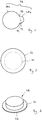
- a coupling element 48 which has, for example, a circular extent, and a bottom portion 62, which the coupling element 48 with a Handling section 64 (see FIG. 5 ) surmounted.
- the extension of the bottom section 62 deviates from the extent of the coupling element 48.
- the first punching element 54 has an in FIG. 6 schematically illustrated with a dashed line punching contour 72.
- the punch contour 72 extends between a region 74 and a region 76.
- the second punching element 56 has an in FIG. 6 punched contour 78 shown by a solid line, which is composed of a first contour portion 78a and a second contour portion 78b.
- the transitions between the contour sections 78a and 78b are arranged in the regions 74 and 76.
- the deviation of the profile of the contour section 78b from the course of the punch contour 72 determines the geometry and size of the handling section 64.
- the second punching element 56 has a self-contained punching contour 78, while the first punching element 54 has an open, not self-contained punching contour 72.
- the first punching element 54 serves to sever the flat body 42 in the region of a first partial circumference 55 (see FIG FIG. 5 ) of the coupling element 48.
- the partial circumference 55 of the coupling element 48 corresponds to the punching contour 72 of the first punching element 54 extending between the regions 74 and 76 (cf. FIG. 6 ).
- the second punching element 56 serves to sever the flat body 42 in the region of a second partial circumference 57 adjoining the first partial circumference 55 of the coupling element 48 (cf. FIG. 5 ).
- the partial circumference 57 of the coupling element 48 corresponds to the contour section 78a of the punching contour 78 of the second punching element 56 (cf. FIG. 6 ).
- the second punching element 56 In the area of the second partial circumference 57 of the coupling element 48, the second punching element 56 not only initially punches the flat body 42, but subsequently also the bottom 36 of the mold 16.
- the second contour section 78b of the second punching element 56 likewise initially pierces the flat body 42 and subsequently also the bottom 36 of the mold 16.
- the bottom section 62 punched out by the second punching element 56 with the two contour sections 78a and 78b projects beyond the coupling element 48 in the region of the handling section 64.
- FIG. 7 an alternative course for punching contours of the first punching element 54 and the second punching element 56 of the punching tool 52 is shown.
- the first punching element 54 has alternatively to a punching contour 72 according to FIG. 6 a self-contained, in FIG. 7 punched contour 80 shown with a dashed line.
- the second punching element 56 alternatively has a punched contour 78 according to FIG FIG. 6 one with a solid line illustrated punching contour 82.
- the punched contours 80 and / or 82 are, for example, circular.
- a circumferential, for example annular, handling section 64 can be produced, which projects beyond a coupling element 48 in all directions (cf. FIG. 8 ).
- a circumferential, for example annular, handling section 64 can be produced, which projects beyond a coupling element 48 in all directions (cf. FIG. 8 ).
- FIG. 8 additionally generates an annular material section, not shown in the drawing, which surrounds the coupling element 48. This material portion is formed in an annular space between the punching elements 54 and 56 and can be lifted and disposed of the flat body 42 of the annular handling portion 64 after removal / lifting of the punch 52.
- a plurality of punching tools 52 can advantageously be combined to form a punching tool arrangement in order to simultaneously cut out a plurality of coupling elements 48 from a flat body 42 in one punching operation.
- the mold 16 may be masked to avoid potential trapping of dust or other debris during the curing process. Furthermore, it is optionally possible, in particular before the removal of a coupling element 48 from the flat body 42, to lay a protective film on the already hardened or on the still to be hardened flat body 42.
- the protective element 70 or the protective elements protects or protects a coupling element 48 directly from its production and until immediately before the assembly of the coupling element 48 on the inside of a vehicle window, in which the coupling element 48 between the inside of a vehicle window and the coupling surface of an optical sensor is arranged.
Landscapes
- Engineering & Computer Science (AREA)
- Mechanical Engineering (AREA)
- Life Sciences & Earth Sciences (AREA)
- Forests & Forestry (AREA)
- Physics & Mathematics (AREA)
- Health & Medical Sciences (AREA)
- General Health & Medical Sciences (AREA)
- Optics & Photonics (AREA)
- Toxicology (AREA)
- Manufacturing & Machinery (AREA)
- Casting Or Compression Moulding Of Plastics Or The Like (AREA)
- Moulds For Moulding Plastics Or The Like (AREA)
Claims (15)
- Procédé de production d'un élément de couplage optique (48) en élastomère, comprenant les étapes consistant à :- verser une formulation d'élastomère pouvant s'écouler ou des constituants de celle-ci dans un moule (16) pour produire un corps plat (42), dont l'épaisseur (44) est adaptée à l'épaisseur (46) d'un élément de couplage (48) à produire,- durcir pour former un élastomère de forme stable,- découper des éléments de couplage individuels (48) à partir du corps plat (42).
- Procédé selon la revendication 1, caractérisé en ce que la découpe a lieu pendant que le corps plat (42) est disposé dans le moule (16).
- Procédé selon l'une quelconque des revendications précédentes, caractérisé en ce qu'un tronçon de fond (62) du fond (36) du moule est découpé (16), dans lequel le tronçon de fond (62) forme un élément de protection (70) pouvant être détaché de l'élément de couplage (48) pour un côté inférieur (68) de l'élément de couplage (48).
- Procédé selon la revendication 3, caractérisé en ce que le tronçon de fond (62) et l'élément de couplage (48) présentant de grandes surfaces identiques.
- Procédé selon la revendication 3, caractérisé en ce que le tronçon de fond (62) de l'élément de couplage (48) dépasse en termes de surface avec au moins un tronçon de manipulation (64).
- Procédé selon l'une quelconque des revendications précédentes, caractérisé en ce que la découpe est effectuée par poinçonnage, découpe à l'eau ou au laser.
- Procédé selon l'une quelconque des revendications précédentes, caractérisé en ce qu'un film de protection est utilisé comme élément de protection pouvant être détaché de l'élément de couplage (48) pour un côté supérieur (66) de l'élément de couplage (48).
- Procédé selon la revendication 7, caractérisé en ce que l'élément de protection est pourvu d'une partie de préhension qui facilite le détachement de l'élément de protection depuis l'élément de couplage (48).
- Dispositif (10) pour produire un élément de couplage optique (48) en élastomère, comprenant un moule (16) pour le versement d' une formulation d'élastomère pouvant s'écouler ou de composants de celle-ci pour la production d'un corps plat (42) dont l'épaisseur (44) est adaptée à l'épaisseur (46) d'un élément de couplage (48) à produire, et un outil de découpe (50) pour découper des éléments de couplage individuels (48) à partir du corps plat (42).
- Dispositif (10) selon la revendication 9, caractérisé en ce que le moule (16) est réalisé en une matière plastique.
- Dispositif (10) selon la revendication 9 ou 10, caractérisé en ce que le l'outil de découpe (50) est un outil de poinçonnage (52).
- Dispositif (10) selon la revendication 11, caractérisé en ce que l'outil de poinçonnage (52) présente deux éléments de poinçonnage (54, 56) décalés l'un de l'autre lorsque vus dans la direction de poinçonnage (58), dans lequel un premier élément de poinçonnage (54) sert pour la découpe au moins partielle d'un élément de couplage (48) à partir du corps plat (42), et dans lequel un second élément de poinçonnage (56) sert au sectionnement du corps plat (42) et à la découpe d'un tronçon de fond (62) du fond (36) du moule (16).
- Dispositif (10) selon la revendication 12, caractérisé en ce qu'un contour de poinçonnage (78, 82) du second élément de poinçonnage (56) dépasse en termes de surface d'un contour de poinçonnage (72, 80) du premier élément de poinçonnage (54).
- Dispositif (10) selon l'une quelconque des revendications 9 à 13, caractérisé en ce que le dispositif (10) comporte un dispositif d'alignement (12) pour l'alignement du moule (16) dans un plan horizontal.
- Dispositif (10) selon l'une quelconque des revendications 9 à 14, caractérisé en ce que le dispositif (10) comprend un dispositif d'aspiration (14) pour fixer le moule (16) sur une surface de support.
Priority Applications (10)
| Application Number | Priority Date | Filing Date | Title |
|---|---|---|---|
| PL15164586T PL3085520T3 (pl) | 2015-04-22 | 2015-04-22 | Sposób i urządzenie do wytwarzania optycznego elementu sprzęgającego z elastomeru |
| ES15164586.8T ES2640634T3 (es) | 2015-04-22 | 2015-04-22 | Procedimiento y dispositivo para la fabricación de un elemento de acoplamiento óptico hecho de un elastómero |
| EP15164586.8A EP3085520B1 (fr) | 2015-04-22 | 2015-04-22 | Procédé et dispositif de production d'un élément de couplage optique en élastomère |
| SI201530088T SI3085520T1 (sl) | 2015-04-22 | 2015-04-22 | Postopek in naprava za proizvodnjo optičnega sklopnega elementa izdelanega iz elastomera |
| US15/542,078 US10300636B2 (en) | 2015-04-22 | 2016-04-18 | Method and device for producing an optical coupling element made of elastomer |
| AU2016251152A AU2016251152B2 (en) | 2015-04-22 | 2016-04-18 | Method and device for producing an optical coupling element made of elastomer |
| PCT/EP2016/058481 WO2016169870A2 (fr) | 2015-04-22 | 2016-04-18 | Procédé et dispositif de fabrication d'un élément de couplage optique en élastomère |
| JP2017550680A JP6371484B2 (ja) | 2015-04-22 | 2016-04-18 | エラストマーから光学結合部材を製造する方法および装置 |
| CN201680011403.3A CN107428093B (zh) | 2015-04-22 | 2016-04-18 | 用于由弹性体制作光学耦合元件的设备和方法 |
| ZA2017/05017A ZA201705017B (en) | 2015-04-22 | 2017-07-24 | Method and device for producing an optical coupling element made of elastomer |
Applications Claiming Priority (1)
| Application Number | Priority Date | Filing Date | Title |
|---|---|---|---|
| EP15164586.8A EP3085520B1 (fr) | 2015-04-22 | 2015-04-22 | Procédé et dispositif de production d'un élément de couplage optique en élastomère |
Publications (2)
| Publication Number | Publication Date |
|---|---|
| EP3085520A1 EP3085520A1 (fr) | 2016-10-26 |
| EP3085520B1 true EP3085520B1 (fr) | 2017-07-19 |
Family
ID=53008312
Family Applications (1)
| Application Number | Title | Priority Date | Filing Date |
|---|---|---|---|
| EP15164586.8A Active EP3085520B1 (fr) | 2015-04-22 | 2015-04-22 | Procédé et dispositif de production d'un élément de couplage optique en élastomère |
Country Status (10)
| Country | Link |
|---|---|
| US (1) | US10300636B2 (fr) |
| EP (1) | EP3085520B1 (fr) |
| JP (1) | JP6371484B2 (fr) |
| CN (1) | CN107428093B (fr) |
| AU (1) | AU2016251152B2 (fr) |
| ES (1) | ES2640634T3 (fr) |
| PL (1) | PL3085520T3 (fr) |
| SI (1) | SI3085520T1 (fr) |
| WO (1) | WO2016169870A2 (fr) |
| ZA (1) | ZA201705017B (fr) |
Families Citing this family (1)
| Publication number | Priority date | Publication date | Assignee | Title |
|---|---|---|---|---|
| US11953343B2 (en) * | 2017-07-07 | 2024-04-09 | Marcy Enterprises, Inc. | Packaged sensor pad |
Citations (2)
| Publication number | Priority date | Publication date | Assignee | Title |
|---|---|---|---|---|
| EP1413490A2 (fr) * | 2002-10-22 | 2004-04-28 | Robert Bosch Gmbh | Dispositif de détection ainsi que méthode de montage pour un dispositif de détection |
| DE102006039065A1 (de) * | 2005-08-25 | 2007-03-01 | Leopold Kostal Gmbh & Co. Kg | Befestigungsvorrichtung für einen optischen Sensor an einer Fahrzeugscheibe |
Family Cites Families (14)
| Publication number | Priority date | Publication date | Assignee | Title |
|---|---|---|---|---|
| US2200730A (en) * | 1937-09-17 | 1940-05-14 | Us Rubber Co | Rotary cutter |
| JPH04216911A (ja) * | 1990-12-17 | 1992-08-07 | Kanai Hiroyuki | 弾性樹脂製成形品の製造方法 |
| JP3320478B2 (ja) | 1993-02-23 | 2002-09-03 | 住友スリーエム株式会社 | 粘弾性体を備えた積層体製品の製造方法及び制振材 |
| JP2004265495A (ja) * | 2003-02-28 | 2004-09-24 | Tdk Corp | 光記録媒体製造装置 |
| US20090266396A1 (en) * | 2005-03-29 | 2009-10-29 | Kyocera Corporation | Polycrystalline Silicon Substrate, Method for Producing Same, Polycrystalline Silicon Ingot, Photoelectric Converter and Photoelectric Conversion Module |
| DE102007039776A1 (de) | 2007-08-23 | 2009-02-26 | Leopold Kostal Gmbh & Co. Kg | Optischer Koppelkörper |
| US8414646B2 (en) * | 2007-12-27 | 2013-04-09 | Forsight Labs, Llc | Intraocular, accommodating lens and methods of use |
| DE102008026997B4 (de) * | 2008-06-05 | 2012-06-14 | PMA/Tools Division Autoglas-Zubehör AG | Verfahren und Schablone zum Aufbringen einer Haftschicht auf eine Sensorvorrichtung |
| US8491137B2 (en) * | 2008-09-19 | 2013-07-23 | Magna Mirrors Of America, Inc. | Vehicle mirror assembly with wide angle element |
| JP2011046774A (ja) * | 2009-08-25 | 2011-03-10 | Bridgestone Corp | エネルギー線硬化型エラストマー組成物 |
| DE102011010971A1 (de) * | 2011-02-10 | 2012-08-16 | Leonhard Kurz Stiftung & Co. Kg | Formwerkzeug zum Hinterspritzen einer Kunststofffolie mit einer Kunststoffschmelze |
| JP6275945B2 (ja) * | 2012-12-10 | 2018-02-07 | 日東電工株式会社 | 両面粘着剤付き光学フィルム、およびそれを用いた画像表示装置の製造方法 |
| DE102012025132A1 (de) * | 2012-12-21 | 2014-06-26 | Ferromatik Milacron Gmbh | Verfahren zum Herstellen eines Kunststoff-Formteils sowie Spritzgießmaschine |
| DE102013012849B4 (de) * | 2013-08-02 | 2023-11-16 | HELLA GmbH & Co. KGaA | Optischer Sensor zur Montage an einer Scheibe und Verfahren zur Herstellung eines solchen optischen Sensors |
-
2015
- 2015-04-22 PL PL15164586T patent/PL3085520T3/pl unknown
- 2015-04-22 EP EP15164586.8A patent/EP3085520B1/fr active Active
- 2015-04-22 ES ES15164586.8T patent/ES2640634T3/es active Active
- 2015-04-22 SI SI201530088T patent/SI3085520T1/sl unknown
-
2016
- 2016-04-18 WO PCT/EP2016/058481 patent/WO2016169870A2/fr not_active Ceased
- 2016-04-18 CN CN201680011403.3A patent/CN107428093B/zh active Active
- 2016-04-18 JP JP2017550680A patent/JP6371484B2/ja active Active
- 2016-04-18 AU AU2016251152A patent/AU2016251152B2/en active Active
- 2016-04-18 US US15/542,078 patent/US10300636B2/en active Active
-
2017
- 2017-07-24 ZA ZA2017/05017A patent/ZA201705017B/en unknown
Patent Citations (2)
| Publication number | Priority date | Publication date | Assignee | Title |
|---|---|---|---|---|
| EP1413490A2 (fr) * | 2002-10-22 | 2004-04-28 | Robert Bosch Gmbh | Dispositif de détection ainsi que méthode de montage pour un dispositif de détection |
| DE102006039065A1 (de) * | 2005-08-25 | 2007-03-01 | Leopold Kostal Gmbh & Co. Kg | Befestigungsvorrichtung für einen optischen Sensor an einer Fahrzeugscheibe |
Also Published As
| Publication number | Publication date |
|---|---|
| US10300636B2 (en) | 2019-05-28 |
| WO2016169870A3 (fr) | 2017-04-13 |
| PL3085520T3 (pl) | 2017-12-29 |
| WO2016169870A2 (fr) | 2016-10-27 |
| US20180001518A1 (en) | 2018-01-04 |
| EP3085520A1 (fr) | 2016-10-26 |
| AU2016251152B2 (en) | 2018-03-01 |
| ES2640634T3 (es) | 2017-11-03 |
| JP2018516776A (ja) | 2018-06-28 |
| CN107428093B (zh) | 2018-11-20 |
| JP6371484B2 (ja) | 2018-08-08 |
| CN107428093A (zh) | 2017-12-01 |
| ZA201705017B (en) | 2019-12-18 |
| AU2016251152A1 (en) | 2017-09-21 |
| SI3085520T1 (sl) | 2017-10-30 |
Similar Documents
| Publication | Publication Date | Title |
|---|---|---|
| DE69228553T2 (de) | Vorrichtung und verfahren zum herstellen eines spritzgegossenen rahmens mit einem platteneinsatz | |
| DE2952591A1 (de) | Verfahren zum fertigen von brandsohlen fuer schuhwerk | |
| EP3046789A1 (fr) | Filtre à air pour dispositif d'aération d'un véhicule automobile et procédé pour son montage | |
| DE102013223982A1 (de) | Verfahren zum Herstellung von aus thermoplastischem Material gefertigten Teilen und entsprechende Formvorrichtung | |
| EP3085520B1 (fr) | Procédé et dispositif de production d'un élément de couplage optique en élastomère | |
| EP3222399B1 (fr) | Dispositif et procede de fabrication d'un objet moule presentant au moins une percee | |
| EP1904282B1 (fr) | Dispositif et procede pour eliminer une bavure oblongue sur une piece moulee | |
| DE2831619A1 (de) | Stanz- und rillwerkzeug | |
| DE4401903C1 (de) | Verfahren und Vorrichtung zum Kaschieren eines Bauteiles | |
| EP4350104B1 (fr) | Barre de support pour former un caillebotis et caillebotis comprenant une telle barre de support et un élément de couverture | |
| DE10230001A1 (de) | Deckel für Getränkekartonverbundpackungen sowie Werkzeuge und Verfahren zur Herstellung eines solchen Deckels sowie damit versehene Getränkekartonverbundpackungen | |
| EP3600971B1 (fr) | Élément d'affichage, procédé servant à fabriquer un élément d'affichage et utilisation d'un élément d'affichage et véhicule comprenant un élément d'affichage | |
| DE4339480A1 (de) | Vorrichtung zum Ausstanzen von Formteilen aus einer Formteilbahn | |
| DE3131820A1 (de) | Verfahren zur herstellung einer verbundplatte | |
| DE202015005807U1 (de) | Verbundbaustein, Verwendung und Verbundvorrichtung | |
| EP1737637A1 (fr) | Dispositif pour revetir partiellement par extrusion des elements d'insertion metalliques dans un outil de moulage par injection | |
| EP1398137B1 (fr) | Tampon de laminage comprenant un élément élastique, presse de laminage et procédé de fabrication | |
| DE102004056451A1 (de) | Werkzeug und Verfahren zur Herstellung von Formkörpern mit Öffnungen | |
| EP3498961A1 (fr) | Bloc de montage | |
| DE102019122627B4 (de) | Verfahren zur Herstellung eines 2K-Kunststoffzierteils und 2K-Kunststoffzierteil | |
| EP3756780B1 (fr) | Procédé de production d'une partie de matière affaiblie dans un composant | |
| DE19627387A1 (de) | Vorrichtung zum Hinterform-Pressen eines mit einer Dekorfolie zu versehenden Kunststoff-Trägerteiles | |
| DE19851731C1 (de) | Tiefziehverfahren für Folien aus thermoplastischem oder kalt-reckbarem Kunststoff | |
| EP1943920A1 (fr) | Dispositif destiné au transport et/ou au rangement d'objets et son procédé de fabrication | |
| EP0673738B1 (fr) | Evier moulé à encastrer avec pièce d'insertion, et procédé pour sa fabrication |
Legal Events
| Date | Code | Title | Description |
|---|---|---|---|
| PUAI | Public reference made under article 153(3) epc to a published international application that has entered the european phase |
Free format text: ORIGINAL CODE: 0009012 |
|
| 17P | Request for examination filed |
Effective date: 20160331 |
|
| AK | Designated contracting states |
Kind code of ref document: A1 Designated state(s): AL AT BE BG CH CY CZ DE DK EE ES FI FR GB GR HR HU IE IS IT LI LT LU LV MC MK MT NL NO PL PT RO RS SE SI SK SM TR |
|
| AX | Request for extension of the european patent |
Extension state: BA ME |
|
| GRAP | Despatch of communication of intention to grant a patent |
Free format text: ORIGINAL CODE: EPIDOSNIGR1 |
|
| RIC1 | Information provided on ipc code assigned before grant |
Ipc: B29C 69/00 20060101AFI20170216BHEP Ipc: B60S 1/08 20060101ALI20170216BHEP Ipc: B29C 39/30 20060101ALN20170216BHEP Ipc: B26F 1/38 20060101ALI20170216BHEP |
|
| INTG | Intention to grant announced |
Effective date: 20170228 |
|
| RIC1 | Information provided on ipc code assigned before grant |
Ipc: B29C 69/00 20060101AFI20170217BHEP Ipc: B60S 1/08 20060101ALI20170217BHEP Ipc: B29C 39/30 20060101ALN20170217BHEP Ipc: B26F 1/38 20060101ALI20170217BHEP |
|
| GRAS | Grant fee paid |
Free format text: ORIGINAL CODE: EPIDOSNIGR3 |
|
| GRAA | (expected) grant |
Free format text: ORIGINAL CODE: 0009210 |
|
| AK | Designated contracting states |
Kind code of ref document: B1 Designated state(s): AL AT BE BG CH CY CZ DE DK EE ES FI FR GB GR HR HU IE IS IT LI LT LU LV MC MK MT NL NO PL PT RO RS SE SI SK SM TR |
|
| REG | Reference to a national code |
Ref country code: GB Ref legal event code: FG4D Free format text: NOT ENGLISH |
|
| REG | Reference to a national code |
Ref country code: CH Ref legal event code: EP |
|
| REG | Reference to a national code |
Ref country code: IE Ref legal event code: FG4D Free format text: LANGUAGE OF EP DOCUMENT: GERMAN |
|
| REG | Reference to a national code |
Ref country code: CH Ref legal event code: NV Representative=s name: DREISS PATENTANWAELTE PARTG MBB, DE Ref country code: AT Ref legal event code: REF Ref document number: 909967 Country of ref document: AT Kind code of ref document: T Effective date: 20170815 |
|
| REG | Reference to a national code |
Ref country code: DE Ref legal event code: R096 Ref document number: 502015001456 Country of ref document: DE |
|
| REG | Reference to a national code |
Ref country code: NL Ref legal event code: FP |
|
| REG | Reference to a national code |
Ref country code: ES Ref legal event code: FG2A Ref document number: 2640634 Country of ref document: ES Kind code of ref document: T3 Effective date: 20171103 |
|
| REG | Reference to a national code |
Ref country code: LT Ref legal event code: MG4D |
|
| PG25 | Lapsed in a contracting state [announced via postgrant information from national office to epo] |
Ref country code: NO Free format text: LAPSE BECAUSE OF FAILURE TO SUBMIT A TRANSLATION OF THE DESCRIPTION OR TO PAY THE FEE WITHIN THE PRESCRIBED TIME-LIMIT Effective date: 20171019 Ref country code: SE Free format text: LAPSE BECAUSE OF FAILURE TO SUBMIT A TRANSLATION OF THE DESCRIPTION OR TO PAY THE FEE WITHIN THE PRESCRIBED TIME-LIMIT Effective date: 20170719 Ref country code: LT Free format text: LAPSE BECAUSE OF FAILURE TO SUBMIT A TRANSLATION OF THE DESCRIPTION OR TO PAY THE FEE WITHIN THE PRESCRIBED TIME-LIMIT Effective date: 20170719 Ref country code: HR Free format text: LAPSE BECAUSE OF FAILURE TO SUBMIT A TRANSLATION OF THE DESCRIPTION OR TO PAY THE FEE WITHIN THE PRESCRIBED TIME-LIMIT Effective date: 20170719 Ref country code: FI Free format text: LAPSE BECAUSE OF FAILURE TO SUBMIT A TRANSLATION OF THE DESCRIPTION OR TO PAY THE FEE WITHIN THE PRESCRIBED TIME-LIMIT Effective date: 20170719 |
|
| PG25 | Lapsed in a contracting state [announced via postgrant information from national office to epo] |
Ref country code: RS Free format text: LAPSE BECAUSE OF FAILURE TO SUBMIT A TRANSLATION OF THE DESCRIPTION OR TO PAY THE FEE WITHIN THE PRESCRIBED TIME-LIMIT Effective date: 20170719 Ref country code: IS Free format text: LAPSE BECAUSE OF FAILURE TO SUBMIT A TRANSLATION OF THE DESCRIPTION OR TO PAY THE FEE WITHIN THE PRESCRIBED TIME-LIMIT Effective date: 20171119 Ref country code: LV Free format text: LAPSE BECAUSE OF FAILURE TO SUBMIT A TRANSLATION OF THE DESCRIPTION OR TO PAY THE FEE WITHIN THE PRESCRIBED TIME-LIMIT Effective date: 20170719 |
|
| REG | Reference to a national code |
Ref country code: GR Ref legal event code: EP Ref document number: 20170402597 Country of ref document: GR Effective date: 20180309 |
|
| REG | Reference to a national code |
Ref country code: DE Ref legal event code: R097 Ref document number: 502015001456 Country of ref document: DE |
|
| REG | Reference to a national code |
Ref country code: FR Ref legal event code: PLFP Year of fee payment: 4 |
|
| PG25 | Lapsed in a contracting state [announced via postgrant information from national office to epo] |
Ref country code: CZ Free format text: LAPSE BECAUSE OF FAILURE TO SUBMIT A TRANSLATION OF THE DESCRIPTION OR TO PAY THE FEE WITHIN THE PRESCRIBED TIME-LIMIT Effective date: 20170719 Ref country code: DK Free format text: LAPSE BECAUSE OF FAILURE TO SUBMIT A TRANSLATION OF THE DESCRIPTION OR TO PAY THE FEE WITHIN THE PRESCRIBED TIME-LIMIT Effective date: 20170719 |
|
| PLBE | No opposition filed within time limit |
Free format text: ORIGINAL CODE: 0009261 |
|
| STAA | Information on the status of an ep patent application or granted ep patent |
Free format text: STATUS: NO OPPOSITION FILED WITHIN TIME LIMIT |
|
| PG25 | Lapsed in a contracting state [announced via postgrant information from national office to epo] |
Ref country code: EE Free format text: LAPSE BECAUSE OF FAILURE TO SUBMIT A TRANSLATION OF THE DESCRIPTION OR TO PAY THE FEE WITHIN THE PRESCRIBED TIME-LIMIT Effective date: 20170719 Ref country code: SK Free format text: LAPSE BECAUSE OF FAILURE TO SUBMIT A TRANSLATION OF THE DESCRIPTION OR TO PAY THE FEE WITHIN THE PRESCRIBED TIME-LIMIT Effective date: 20170719 Ref country code: SM Free format text: LAPSE BECAUSE OF FAILURE TO SUBMIT A TRANSLATION OF THE DESCRIPTION OR TO PAY THE FEE WITHIN THE PRESCRIBED TIME-LIMIT Effective date: 20170719 |
|
| 26N | No opposition filed |
Effective date: 20180420 |
|
| PG25 | Lapsed in a contracting state [announced via postgrant information from national office to epo] |
Ref country code: MT Free format text: LAPSE BECAUSE OF FAILURE TO SUBMIT A TRANSLATION OF THE DESCRIPTION OR TO PAY THE FEE WITHIN THE PRESCRIBED TIME-LIMIT Effective date: 20170719 |
|
| PG25 | Lapsed in a contracting state [announced via postgrant information from national office to epo] |
Ref country code: MC Free format text: LAPSE BECAUSE OF FAILURE TO SUBMIT A TRANSLATION OF THE DESCRIPTION OR TO PAY THE FEE WITHIN THE PRESCRIBED TIME-LIMIT Effective date: 20170719 |
|
| REG | Reference to a national code |
Ref country code: IE Ref legal event code: MM4A |
|
| PG25 | Lapsed in a contracting state [announced via postgrant information from national office to epo] |
Ref country code: LU Free format text: LAPSE BECAUSE OF NON-PAYMENT OF DUE FEES Effective date: 20180422 |
|
| PG25 | Lapsed in a contracting state [announced via postgrant information from national office to epo] |
Ref country code: IE Free format text: LAPSE BECAUSE OF NON-PAYMENT OF DUE FEES Effective date: 20180422 |
|
| PG25 | Lapsed in a contracting state [announced via postgrant information from national office to epo] |
Ref country code: TR Free format text: LAPSE BECAUSE OF FAILURE TO SUBMIT A TRANSLATION OF THE DESCRIPTION OR TO PAY THE FEE WITHIN THE PRESCRIBED TIME-LIMIT Effective date: 20170719 |
|
| PG25 | Lapsed in a contracting state [announced via postgrant information from national office to epo] |
Ref country code: PT Free format text: LAPSE BECAUSE OF FAILURE TO SUBMIT A TRANSLATION OF THE DESCRIPTION OR TO PAY THE FEE WITHIN THE PRESCRIBED TIME-LIMIT Effective date: 20170719 |
|
| PG25 | Lapsed in a contracting state [announced via postgrant information from national office to epo] |
Ref country code: CY Free format text: LAPSE BECAUSE OF FAILURE TO SUBMIT A TRANSLATION OF THE DESCRIPTION OR TO PAY THE FEE WITHIN THE PRESCRIBED TIME-LIMIT Effective date: 20170719 Ref country code: HU Free format text: LAPSE BECAUSE OF FAILURE TO SUBMIT A TRANSLATION OF THE DESCRIPTION OR TO PAY THE FEE WITHIN THE PRESCRIBED TIME-LIMIT; INVALID AB INITIO Effective date: 20150422 Ref country code: MK Free format text: LAPSE BECAUSE OF NON-PAYMENT OF DUE FEES Effective date: 20170719 Ref country code: RO Free format text: LAPSE BECAUSE OF FAILURE TO SUBMIT A TRANSLATION OF THE DESCRIPTION OR TO PAY THE FEE WITHIN THE PRESCRIBED TIME-LIMIT Effective date: 20170719 |
|
| PG25 | Lapsed in a contracting state [announced via postgrant information from national office to epo] |
Ref country code: AL Free format text: LAPSE BECAUSE OF FAILURE TO SUBMIT A TRANSLATION OF THE DESCRIPTION OR TO PAY THE FEE WITHIN THE PRESCRIBED TIME-LIMIT Effective date: 20170719 |
|
| REG | Reference to a national code |
Ref country code: AT Ref legal event code: MM01 Ref document number: 909967 Country of ref document: AT Kind code of ref document: T Effective date: 20200422 |
|
| PG25 | Lapsed in a contracting state [announced via postgrant information from national office to epo] |
Ref country code: AT Free format text: LAPSE BECAUSE OF NON-PAYMENT OF DUE FEES Effective date: 20200422 |
|
| PGFP | Annual fee paid to national office [announced via postgrant information from national office to epo] |
Ref country code: NL Payment date: 20220419 Year of fee payment: 8 |
|
| PGFP | Annual fee paid to national office [announced via postgrant information from national office to epo] |
Ref country code: BG Payment date: 20220414 Year of fee payment: 8 |
|
| PGFP | Annual fee paid to national office [announced via postgrant information from national office to epo] |
Ref country code: SI Payment date: 20220413 Year of fee payment: 8 Ref country code: GR Payment date: 20220419 Year of fee payment: 8 Ref country code: BE Payment date: 20220419 Year of fee payment: 8 |
|
| P01 | Opt-out of the competence of the unified patent court (upc) registered |
Effective date: 20230515 |
|
| REG | Reference to a national code |
Ref country code: NL Ref legal event code: MM Effective date: 20230501 |
|
| REG | Reference to a national code |
Ref country code: BE Ref legal event code: MM Effective date: 20230430 |
|
| PG25 | Lapsed in a contracting state [announced via postgrant information from national office to epo] |
Ref country code: GR Free format text: LAPSE BECAUSE OF NON-PAYMENT OF DUE FEES Effective date: 20231110 |
|
| PG25 | Lapsed in a contracting state [announced via postgrant information from national office to epo] |
Ref country code: SI Free format text: LAPSE BECAUSE OF NON-PAYMENT OF DUE FEES Effective date: 20230423 Ref country code: NL Free format text: LAPSE BECAUSE OF NON-PAYMENT OF DUE FEES Effective date: 20230501 Ref country code: GR Free format text: LAPSE BECAUSE OF NON-PAYMENT OF DUE FEES Effective date: 20231110 |
|
| PG25 | Lapsed in a contracting state [announced via postgrant information from national office to epo] |
Ref country code: BE Free format text: LAPSE BECAUSE OF NON-PAYMENT OF DUE FEES Effective date: 20230430 |
|
| REG | Reference to a national code |
Ref country code: SI Ref legal event code: KO00 Effective date: 20240115 |
|
| PG25 | Lapsed in a contracting state [announced via postgrant information from national office to epo] |
Ref country code: BG Free format text: LAPSE BECAUSE OF NON-PAYMENT OF DUE FEES Effective date: 20230422 |
|
| PG25 | Lapsed in a contracting state [announced via postgrant information from national office to epo] |
Ref country code: BG Free format text: LAPSE BECAUSE OF NON-PAYMENT OF DUE FEES Effective date: 20230422 |
|
| REG | Reference to a national code |
Ref country code: DE Ref legal event code: R081 Ref document number: 502015001456 Country of ref document: DE Owner name: PMA/TOOLS GMBH, DE Free format text: FORMER OWNER: PMA/TOOLS AG, 47877 WILLICH, DE |
|
| PGFP | Annual fee paid to national office [announced via postgrant information from national office to epo] |
Ref country code: PL Payment date: 20250401 Year of fee payment: 11 Ref country code: DE Payment date: 20250611 Year of fee payment: 11 |
|
| PGFP | Annual fee paid to national office [announced via postgrant information from national office to epo] |
Ref country code: ES Payment date: 20250519 Year of fee payment: 11 |
|
| PGFP | Annual fee paid to national office [announced via postgrant information from national office to epo] |
Ref country code: IT Payment date: 20250422 Year of fee payment: 11 |
|
| PGFP | Annual fee paid to national office [announced via postgrant information from national office to epo] |
Ref country code: FR Payment date: 20250425 Year of fee payment: 11 |
|
| PGFP | Annual fee paid to national office [announced via postgrant information from national office to epo] |
Ref country code: CH Payment date: 20250501 Year of fee payment: 11 |
|
| REG | Reference to a national code |
Ref country code: ES Ref legal event code: PC2A Owner name: PMA/TOOLS GMBH Effective date: 20251103 |
|
| PGFP | Annual fee paid to national office [announced via postgrant information from national office to epo] |
Ref country code: GB Payment date: 20260327 Year of fee payment: 12 |