EP3085835B1 - Gicleur et méthode d'arrosage d'une surface routière - Google Patents
Gicleur et méthode d'arrosage d'une surface routière Download PDFInfo
- Publication number
- EP3085835B1 EP3085835B1 EP15165006.6A EP15165006A EP3085835B1 EP 3085835 B1 EP3085835 B1 EP 3085835B1 EP 15165006 A EP15165006 A EP 15165006A EP 3085835 B1 EP3085835 B1 EP 3085835B1
- Authority
- EP
- European Patent Office
- Prior art keywords
- sprinkler
- recess
- cross
- spray
- recesses
- Prior art date
- Legal status (The legal status is an assumption and is not a legal conclusion. Google has not performed a legal analysis and makes no representation as to the accuracy of the status listed.)
- Active
Links
Images


Classifications
-
- B—PERFORMING OPERATIONS; TRANSPORTING
- B05—SPRAYING OR ATOMISING IN GENERAL; APPLYING FLUENT MATERIALS TO SURFACES, IN GENERAL
- B05B—SPRAYING APPARATUS; ATOMISING APPARATUS; NOZZLES
- B05B12/00—Arrangements for controlling delivery; Arrangements for controlling the spray area
- B05B12/16—Arrangements for controlling delivery; Arrangements for controlling the spray area for controlling the spray area
-
- B—PERFORMING OPERATIONS; TRANSPORTING
- B05—SPRAYING OR ATOMISING IN GENERAL; APPLYING FLUENT MATERIALS TO SURFACES, IN GENERAL
- B05B—SPRAYING APPARATUS; ATOMISING APPARATUS; NOZZLES
- B05B1/00—Nozzles, spray heads or other outlets, with or without auxiliary devices such as valves, heating means
- B05B1/14—Nozzles, spray heads or other outlets, with or without auxiliary devices such as valves, heating means with multiple outlet openings; with strainers in or outside the outlet opening
-
- B—PERFORMING OPERATIONS; TRANSPORTING
- B05—SPRAYING OR ATOMISING IN GENERAL; APPLYING FLUENT MATERIALS TO SURFACES, IN GENERAL
- B05B—SPRAYING APPARATUS; ATOMISING APPARATUS; NOZZLES
- B05B1/00—Nozzles, spray heads or other outlets, with or without auxiliary devices such as valves, heating means
- B05B1/26—Nozzles, spray heads or other outlets, with or without auxiliary devices such as valves, heating means with means for mechanically breaking-up or deflecting the jet after discharge, e.g. with fixed deflectors; Breaking-up the discharged liquid or other fluent material by impinging jets
- B05B1/262—Nozzles, spray heads or other outlets, with or without auxiliary devices such as valves, heating means with means for mechanically breaking-up or deflecting the jet after discharge, e.g. with fixed deflectors; Breaking-up the discharged liquid or other fluent material by impinging jets with fixed deflectors
- B05B1/267—Nozzles, spray heads or other outlets, with or without auxiliary devices such as valves, heating means with means for mechanically breaking-up or deflecting the jet after discharge, e.g. with fixed deflectors; Breaking-up the discharged liquid or other fluent material by impinging jets with fixed deflectors the liquid or other fluent material being deflected in determined directions
-
- B—PERFORMING OPERATIONS; TRANSPORTING
- B05—SPRAYING OR ATOMISING IN GENERAL; APPLYING FLUENT MATERIALS TO SURFACES, IN GENERAL
- B05B—SPRAYING APPARATUS; ATOMISING APPARATUS; NOZZLES
- B05B1/00—Nozzles, spray heads or other outlets, with or without auxiliary devices such as valves, heating means
- B05B1/30—Nozzles, spray heads or other outlets, with or without auxiliary devices such as valves, heating means designed to control volume of flow, e.g. with adjustable passages
- B05B1/3033—Nozzles, spray heads or other outlets, with or without auxiliary devices such as valves, heating means designed to control volume of flow, e.g. with adjustable passages the control being effected by relative coaxial longitudinal movement of the controlling element and the spray head
- B05B1/3073—Nozzles, spray heads or other outlets, with or without auxiliary devices such as valves, heating means designed to control volume of flow, e.g. with adjustable passages the control being effected by relative coaxial longitudinal movement of the controlling element and the spray head the controlling element being a deflector acting as a valve in co-operation with the outlet orifice
-
- B—PERFORMING OPERATIONS; TRANSPORTING
- B05—SPRAYING OR ATOMISING IN GENERAL; APPLYING FLUENT MATERIALS TO SURFACES, IN GENERAL
- B05B—SPRAYING APPARATUS; ATOMISING APPARATUS; NOZZLES
- B05B15/00—Details of spraying plant or spraying apparatus not otherwise provided for; Accessories
- B05B15/60—Arrangements for mounting, supporting or holding spraying apparatus
- B05B15/68—Arrangements for adjusting the position of spray heads
-
- E—FIXED CONSTRUCTIONS
- E01—CONSTRUCTION OF ROADS, RAILWAYS, OR BRIDGES
- E01H—STREET CLEANING; CLEANING OF PERMANENT WAYS; CLEANING BEACHES; DISPERSING OR PREVENTING FOG IN GENERAL CLEANING STREET OR RAILWAY FURNITURE OR TUNNEL WALLS
- E01H3/00—Applying liquids to roads or like surfaces, e.g. for dust control; Stationary flushing devices
- E01H3/04—Fixed devices, e.g. permanently- installed flushing means
-
- B—PERFORMING OPERATIONS; TRANSPORTING
- B05—SPRAYING OR ATOMISING IN GENERAL; APPLYING FLUENT MATERIALS TO SURFACES, IN GENERAL
- B05B—SPRAYING APPARATUS; ATOMISING APPARATUS; NOZZLES
- B05B1/00—Nozzles, spray heads or other outlets, with or without auxiliary devices such as valves, heating means
- B05B1/30—Nozzles, spray heads or other outlets, with or without auxiliary devices such as valves, heating means designed to control volume of flow, e.g. with adjustable passages
- B05B1/3026—Gate valves; Sliding valves; Cocks
-
- B—PERFORMING OPERATIONS; TRANSPORTING
- B05—SPRAYING OR ATOMISING IN GENERAL; APPLYING FLUENT MATERIALS TO SURFACES, IN GENERAL
- B05B—SPRAYING APPARATUS; ATOMISING APPARATUS; NOZZLES
- B05B7/00—Spraying apparatus for discharge of liquids or other fluent materials from two or more sources, e.g. of liquid and air, of powder and gas
- B05B7/02—Spray pistols; Apparatus for discharge
- B05B7/08—Spray pistols; Apparatus for discharge with separate outlet orifices, e.g. to form parallel jets, i.e. the axis of the jets being parallel, to form intersecting jets, i.e. the axis of the jets converging but not necessarily intersecting at a point
- B05B7/0892—Spray pistols; Apparatus for discharge with separate outlet orifices, e.g. to form parallel jets, i.e. the axis of the jets being parallel, to form intersecting jets, i.e. the axis of the jets converging but not necessarily intersecting at a point the outlet orifices for jets constituted by a liquid or a mixture containing a liquid being disposed on a circle
Definitions
- the invention relates to a sprinkler for irrigating a roadway such as a driving technique track or a test track with outlet openings for dispensing a liquid.
- the invention further relates to a method for irrigating a roadway, in particular a driving technique route or a test route, with a sprinkler.
- Sprinklers for irrigating a road have become known from the prior art, for example in order to artificially produce a reduced coefficient of friction between the road and a tire of a motor vehicle for driving technique training or a test of vehicles.
- the object of the invention is to provide a sprinkler of the type mentioned, with which a particularly realistic wet road surface can be achieved.
- the first object is achieved according to the invention by a sprinkler according to claim 1.
- a spray insert is arranged in the sprinkler, recesses in the spray insert at least partially defining the outlet openings of the sprinkler.
- the spray insert is positioned in a nozzle of the sprinkler, the outlet openings, which are partially defined by recesses, connecting a central space or an interior of the sprinkler to an exterior, in which central space the water pressure is present when the sprinkler is in operation.
- the cross section of the recess increases along a longitudinal axis of the recess, usually in a direction in which a liquid flows through the spray insert when the spray insert is inserted in the sprinkler.
- the increase in cross section can be provided continuously and continuously over an entire length of the recess from an inner end to an outer end. However, it can also be provided that only a region of an outer end of the recess has a cross-section which increases from the outside or an outside opening angle which leads to a fanning out of the water jet according to the invention when it exits the outlet opening.
- a spray pattern with a spray angle of maximum 180 ° results at a water pressure of approximately 1 bar, a ratio of a length of the spray pattern to a width of the spray pattern 2 to 4 , preferably 2.5 to 3.5, in particular 2.8 to 3.2.
- a region of the roadway is defined as the spray pattern, which area is wetted directly with liquid by water or another liquid emerging from the sprinkler when the sprinkler is in operation.
- the length of the spray pattern and the width of the spray pattern make it a thought Rectangle described, which, with a minimal size of the rectangle, circumscribes an area on the roadway in which the sprinkler is arranged on the one hand and within which liquid escaping from the sprinkler hits or within which water jets emerging from the sprinkler directly hit the roadway. It is therefore understood that the spray pattern itself generally has no rectangular shape, but can be characterized by a circumscribing rectangle.
- the length of the spray pattern is generally at a sprinkler supply pressure of 0.5 bar to 1.5 bar, generally 3.5 m to 12 m, preferably 5 m to 8 m and a width preferably 1 m to 4 m, in particular 2 m to 3 m.
- the spray pattern has a spray angle of at most 180 °, preferably 150 ° to 180 °, in particular 160 ° to 175 °, preferably approximately 170 °. This results in an advantageous liquid distribution on the road to achieve realistic conditions.
- the spray angle is essentially determined by an arrangement of the outlet openings, so that a defined spray angle can be achieved in a simple manner by corresponding arrangement of the recesses defining the outlet openings.
- a particularly favorable spray characteristic or water distribution results if the recesses have an approximately rectangular, in particular an approximately square, cross section.
- the recesses are covered by a component with a flat or conical surface when installed in the sprinkler, the flat side of the component, for example a fixing screw connecting the spray insert with a nozzle body, covering an open long side of the recess, as a result of which the outlet opening is formed.
- a cross section of an outlet opening is geometrically determined by a corresponding recess in the spray insert.
- a minimum cross-sectional width and a cross-sectional height of the recesses are 1 mm to 3 mm, in particular 1.5 mm to 2.3 mm.
- a particularly uniform wetting of the road is possible with a structurally simple construction of the spray insert if 10 to 15, in particular 11 to 13, recesses are provided.
- the spray insert is usually designed as a spray ring with a contour that is essentially rotationally symmetrical about an axis of rotation, in which contour the recesses are arranged.
- the recesses can be made by milling into a rotationally symmetrical basic structure of the spray insert.
- a desired spray pattern can be achieved in a particularly simple manner in that an angle which includes a longitudinal axis of a first recess with a longitudinal axis of a last recess corresponds to the spray angle.
- the first recess and the last recess are those recesses between which further, in particular middle, recesses may be arranged.
- a spray pattern that is favorable for test tracks can be achieved, for example, by different inclination angles of the individual outlet openings with respect to the roadway. Water jets then emerge from all outlet openings at approximately the same speed, but the individual water jets reach different throwing heights or ground clearances, which also results in different throwing distances of the individual water jets.
- a central outlet opening is provided between a first outlet opening and a last outlet opening and has a larger opening angle than the first outlet opening and the last outlet opening. It has proven to be advantageous if at least one central recess is provided in the spray insert, which is arranged between the first recess and the last recess and has a larger minimum cross-sectional area and / or a larger opening angle than the first recess and the last recess.
- the ratio of the minimum cross-sectional area of the at least one central recess to the minimum cross-sectional area of the first recess is approximately 1.1 to 1.8, particularly preferably 1.2 to 1.3, in particular approximately 1.23.
- the recesses usually connect a central space or an interior of the sprinkler, to which an operating pressure of usually 0.5 bar to 1.5 bar is present, with an exterior.
- Different cross-sectional areas of the individual recesses result in different speeds at which water emerges from the individual outlet openings formed by the recess or co-defined by it. This results in different throwing distances or spraying distances of the water jets emerging from the individual outlet openings, so that a spray pattern with a ratio of length to width that is particularly favorable for test purposes can be achieved in a simple manner. Different throwing distances of the individual water jets can thus be achieved with the same and low throwing height of the individual water jets.
- the cross-section or the cross-sectional area of a recess which has a cross-section increasing from an interior to an exterior or an opening angle of more than 0 °, is minimal at an inner end of the recess, at which the water pressure or operating pressure usually occurs during operation is present.
- the minimum cross section consequently also corresponds to a maximum cross section.
- the water jet is also fanned out by recesses which have an opening angle or a cross section which increases from the inside to the outside. Thereby a particularly uniform wetting of the road is guaranteed.
- An angle between the boundary surfaces of the recess, usually between the lateral boundary surfaces of the recesses, is defined as the opening angle, so that an opening angle of more than 0 ° results in a lateral or approximately horizontal fanning out of a water jet.
- minimum cross-sectional areas and / or opening angles of the recesses increase from the first recess to at least one central recess and decrease from the at least one central recess to the last recess. It can be provided that all recesses have different cross-sectional areas or opening angles.
- An embodiment is also possible in which all the recesses between the first recess and the last recess have an identical minimum cross section, which is larger than a minimum cross section of the first recess and a minimum cross section of the last recess. It can further be provided that all the recesses between the first and the last recess have an identical opening angle which is greater than an opening angle of the first recess and the last recess or greater than 0 °.
- a minimum cross-sectional area of the first recess is 3 mm 2 to 5 mm 2 , in particular approximately 3.24 mm 2 .
- the first recess and the last recess have approximately identical cross-sectional areas.
- the first recess and the last recess usually have a cross-section or a constant cross-sectional area that is approximately constant from the inside to the outside, so that an opening angle for these recesses is 0 ° and a minimum cross-section also corresponds to a maximum cross-section of these recesses.
- a minimum cross-sectional area of the at least one central recess is 3 mm 2 to 5 mm 2 , in particular approximately 4 mm 2 , is.
- These recesses advantageously have an increasing cross-sectional area from an interior of the spray insert, which is usually subjected to water pressure during operation, to an exterior along longitudinal axes, so that the recesses have a minimal cross-sectional area in an interior of the spray insert.
- a maximum cross-sectional area of the at least one central recess on an outer edge of the spray insert is generally 5 mm 2 to 10 mm 2 , in particular 6 mm 2 to 8 mm 2 .
- At least one recess in particular a central recess arranged between a first recess and a last recess, has an opening angle of 5 ° to 15 °, in particular 10 ° to 12 °. With this opening angle, both a good fanning out and a sufficient throw range can be achieved.
- At least one recess is generally provided which has a constant cross section from the inside to the outside.
- the lateral recesses or the first recess and the last recess have a constant cross section or a constant cross-sectional area, so that an opening angle of these recesses is 0 ° or boundary surfaces of the recesses are parallel.
- the longitudinal axes of the recesses have a pitch angle of 9 ° to 18 °, preferably 11 ° to 16 °, in particular 12.5 ° to 13.5 °, with respect to a plane which is perpendicular to an imaginary vertical axis of the spray insert.
- the imaginary vertical axis of the spray insert is generally approximately perpendicular to a road surface, so that the angle of inclination corresponds to an angle of the recesses with the road surface when installed, ready for use.
- the vertical axis corresponds to the axis of rotation of the spray insert.
- the outlet openings are only distributed over part of a circumference of the sprinkler, and a central outlet opening is provided between a first outlet opening and a last outlet opening and has a larger opening angle than the first outlet opening and the last outlet opening.
- the outlet openings are distributed over a part of the circumference of the sprinkler of a maximum of 180 °.
- the sprinkler can be easily adapted to different environmental conditions if the spray insert in the sprinkler is arranged to be detachable, in particular rotatable about an axis of rotation. Different characteristics of the sprinkler and a rotation of the spray insert around an imaginary axis of rotation can thus be used to achieve a different spray direction in a simple manner by exchanging the spray insert.
- the sprinkler and the spray insert are formed in one piece, the sprinkler and the spray insert in particular being integrally connected.
- the spray insert can also be part of a nozzle arranged detachably in the sprinkler, wherein the spray insert can be detachably connected to the nozzle or can be an integral part thereof, so that outlet openings of the sprinkler are at least partially defined by the spray insert.
- a sprinkler according to the invention is arranged in the roadway in such a way that a spray pattern with a spray angle occurs when the water pressure at the sprinkler is approximately 1 bar of preferably at most 180 °, a ratio of a length of the spray pattern to a width of the spray pattern being 2 to 4, preferably 2.5 to 3.5, in particular 2.8 to 3.2.
- the further object is achieved by a method of the type mentioned at the outset, wherein water emerges from at least one outlet opening of the sprinkler, which has a cross section which increases from the inside to the outside.
- the associated fanning out of the water jet results in particularly uniform irrigation.
- Irrigation is carried out at a water pressure of about 0.5 bar to 1.5 bar, in particular about 1 bar, and a spray pattern with a spray angle of preferably at most 180 °, a ratio of a length of the spray pattern to a width of the spray pattern 2 to 4, preferably 2.5 to 3.5, in particular 2.8 to 3.2, is.
- the width of the spray pattern is 1 m to 4 m, preferably 2 m to 3 m.
- the water from the sprinkler is inclined at an angle of 9 ° to 18 °, preferably 11 ° to 16 °, in particular 12 5 ° to 13.5 °, opposite the road.
- the irrigation with a water flow of 20 dm 3 / min to 60 dm 3 / min, preferably 30 dm 3 / min to 50 dm 3 / min, in particular about 35 dm 3 / min up to 40 dm 3 / min. This corresponds to the amount of water delivered by the sprinkler to the road.
- Fig. 1 schematically shows a spray pattern 2 of a sprinkler according to the invention in a plan view.
- the spray pattern 2 has a spray angle ⁇ of approximately 170 ° and is formed by 13 water jets 19, which usually emerge from a sprinkler 3 with a spray insert 1.
- the length 6 of the spray pattern 2 is 6 m with a width 7 of approximately 2 m.
- the length 6 and width 7 of the spray pattern 2 indicate dimensions of a rectangle circumscribing an outer contour 18 of the spray pattern 2.
- the outer contour 18 of the spray pattern 2 is essentially determined by the points of impact at which the individual water jets 19 impinge on the carriageway and the position of the in FIG Fig. 1 Sprinklers 3 not shown formed.
- the spray pattern 2 is achieved, as shown, in that the individual water jets 19 have different throwing distances 10, a throwing distance 10 corresponding to a distance from a point from the sprinkler 3 at which the respective water jet 19 touches the roadway or strikes the roadway.
- lateral water jets 19 have larger throwing distances 10 than middle water jets 19, which emerge from middle outlet openings of the sprinkler 3.
- Cross-sections of the outlet openings are essentially defined by cross-sectional areas of recesses 4a, 4b, 4c, 4d of the spray insert 1.
- the different spray widths are achieved by means of different cross sections and different opening angles ⁇ of recesses 4a, 4b, 4c, 4d in the spray insert 1, which with the same pitch angle ⁇ of all recesses 4a, 4b, 4c, 4d at different speeds and an at least partial fanning out of the water jets 19 lead when they exit the sprinkler 3.
- FIG. 4 shows a top view of the spray insert 1.
- Fig. 5 shows a sectional view along the line VV in Fig. 4 .
- the spray insert 1 is approximately rotationally symmetrical about an axis of rotation 5, with recesses 4a, 4b, 4c, 4d not being distributed over an entire circumference.
- the spray insert 1 has recesses 4a, 4b, 4c, 4d, which are arranged distributed over an angle ⁇ of approximately 160 °. All of the recesses 4a, 4b, 4c, 4d have an approximately square cross section in an interior of the spray insert 1, in which essentially the water pressure of the central space 11 is present.
- An inner cross-sectional width 8i and a cross-sectional height 9 each amount to approximately 1.8 mm in a first recess 4a and in a last recess 4c.
- the first recess 4a and the last recess 4c have an approximately constant cross section from the inside to the outside, so that an opening angle ⁇ of 0 ° results in these recesses 4a, 4c. With these recesses 4a, 4c, an inner cross-sectional width 8i consequently corresponds to an outer cross-sectional width 8a.
- Additional recesses 4b, 4d are provided between the first recess 4a and the last recess 4c.
- the recesses 4b, 4d arranged between the first recess 4a and the last recess 4c have an inner cross-sectional width 8i and a cross-sectional height 9 of approximately each 2 mm on. This results in a larger minimum cross-sectional area of these recesses 4b, 4d in an interior of the spray insert than the first recess 4a and the last recess 4c.
- the recesses 4b, 4d arranged between the first recess 4a and the last recess 4c have an opening angle ⁇ which is greater than 0 ° and is usually between 2 ° and 30 °.
- These recesses 4b, 4d thus have a cross section which increases from the inside to the outside.
- the opening angle ⁇ in the exemplary embodiment is approximately 11 °.
- an outer cross-sectional width 8a in these recesses 4b, 4d is larger than an inner cross-sectional width 8i, which means that a cross-sectional area of these recesses 4b, 4d is also larger on the outside than in an interior of the spray insert 1.
- an outer cross-sectional width 8a at the first recess 4a and the last recess 4c is approximately 1.8 mm and increases up to three central recesses 4b, in which the outer cross-sectional width 8a is approximately 3.5 mm.
- a maximum cross-sectional area of the central recess 4b on an exterior of the spray insert is therefore 7 mm 2 .
- the recesses 4d arranged between the first recess 4a and the middle recesses 4b have an outer cross-sectional width 8a which is between 1.8 mm and 3.5 mm.
- all the recesses 4b, 4d between the first recess 4a and the last recess 4c have an identical inner cross-sectional width 8i of 2 mm.
- An alternative embodiment is also possible, in which an inner cross-sectional width 8i of the central recesses 4b is larger than an inner cross-sectional width 8i of the first recess 4a and the last recess 4c, recesses 4d arranged between them having an inner cross-sectional width 8i which is larger than the inner one Cross-sectional width 8i of the first recess 4a and the last recess 4c and smaller than an inner cross-sectional width 8i of the central recesses 4b.
- the spray insert 1 has an outer diameter 20 of approximately 41.5 mm and an inner diameter 21 of approximately 24 mm.
- the spray insert 1 has an inclination angle ⁇ of longitudinal axes 22 of the recesses 4a, 4b, 4c, 4d from about 13 °.
- the spray insert 1 shown has 11 recesses 4a, 4b, 4c, 4d, which are arranged distributed over an angle ⁇ of approximately 160 °. This angle ⁇ is preferably 140 ° to 180 °.
- Fig. 1 spray pattern 2 shown are formed in a particularly simple manner.
- the spray insert 1 is generally arranged in a sprinkler 3 or in a nozzle 16 of a sprinkler 3.
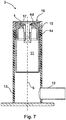
- Fig. 7 and 8 show a sprinkler 3 according to the invention, wherein Fig. 7 the sprinkler 3 in a perspective view and FIG. 8 shows a sectional view of the sprinkler 3.
- the sprinkler 3 described and illustrated also has a sprinkler 3 with a connection 12 for a water supply line, a cladding tube 13, an intermediate part 14, an upper part 15 and a nozzle 16 arranged in the sprinkler 3.
- the sprinkler 3 according to the invention is used to achieve a Fig. 1 shown spray pattern 2 formed.
- a spray insert 1 is arranged in the nozzle 16 and fixed by a fixing screw 17.
- Outlet openings for individual water jets 19 are formed in that an elongated, open side of the recesses 4a, 4b, 4c, 4d is covered by a conical surface of the fixing screw 17. Channels are thus formed which connect an interior or a central space 11 of the sprinkler 3, in which the water pressure is present during operation, to an exterior and have outlet openings with a cross section corresponding to a cross section of the respective recesses 4a, 4b, 4c, 4d.
- the sprinkler 3 is normally arranged in a roadway in such a way that an upper end of the sprinkler 3 is approximately flush with the roadway, so that the outlet openings are positioned approximately at a height of the roadway.
- An axis of rotation 5 of the sprinkler 3, about which the spray insert 1 is preferably rotatably arranged in the sprinkler 3, is approximately perpendicular to a road surface in a working position of the sprinkler 3.
- the sprinkler 3 is operated at a water pressure of approximately 1 bar.
- another liquid can be used instead of water to achieve a wet road or a desired coefficient of friction.
- a spray pattern 2 that can be achieved with the sprinkler according to the invention enables particularly favorable conditions for vehicle dynamics checking by fanning out water jets, with influences being avoided both in a lighting system and in a braking system of vehicles due to a low throwing height.
Landscapes
- Engineering & Computer Science (AREA)
- Architecture (AREA)
- Civil Engineering (AREA)
- Structural Engineering (AREA)
- Nozzles (AREA)
Claims (10)
- Sprinkler (3), destiné à arroser une voie de circulation comme un trajet technique de pilotage ou un circuit d'essai, pourvu d'orifices de sortie pour la distribution d'un liquide, au moins un orifice de sortie présentant une section transversale qui s'accroît d'un intérieur du sprinkler (3) vers un extérieur du sprinkler (3), et ainsi un angle d'ouverture supérieur à 0°, les orifices de sortie étant placés en distribution sur uniquement une partie d'une périphérie du sprinkler (3) et un orifice de sortie central, placé entre un premier orifice de sortie et un dernier orifice de sortie étant prévu, lequel présente un angle d'ouverture (ϕ) supérieur à celui du premier orifice de sortie et du dernier orifice de sortie,
caractérisé en ce que les orifices de sortie sont conçus et placés de telle sorte, que lorsque les orifices de sortie sont positionnés approximativement à la hauteur de la voie de circulation, lorsqu'une pression d'environ 1 bar est appliquée au sprinkler (3), il en résulte un modèle de vaporisation (2) avec un angle de vaporisation (α) d'un maximum de 180°, un rapport d'une longueur (6) du modèle de vaporisation (2) à une largeur (7) du modèle de vaporisation (2) étant de 2 à 4, de préférence de 2,5 à 3,5, notamment de 2,8 à 3,2, au moins un orifice de sortie, notamment l'orifice de sortie central présentant un angle d'ouverture (ϕ) de 5° à 15°. - Sprinkler (3) selon la revendication 1, caractérisé en ce que dans le sprinkler (3) est placé un insert de vaporisation (1), notamment une couronne de vaporisation pourvue d'évidements (4a, 4b, 4c, 4d), lesquels définissent au moins partiellement les orifices de sortie pour la création d'un modèle de vaporisation (2), au moins un évidement (4a, 4b, 4c, 4d) présentant une section transversale qui s'accroît d'un intérieur vers un extérieur.
- Sprinkler (3) selon la revendication 2, caractérisé en ce que les évidements (4a, 4b, 4c, 4d) présentent une section transversale approximativement rectangulaire, notamment une section transversale approximativement quadratique.
- Sprinkler (3) selon l'une quelconque des revendications 2 ou 3, caractérisé en ce qu'une largeur minimale de section transversale (8i) et une hauteur de section transversale (9) des évidements (4a, 4b, 4c, 4d) sont de 1 mm à 3 mm, notamment de 1,5 mm à 2,3 mm.
- Sprinkler selon l'une quelconque des revendications 2 à 4, caractérisé en ce qu'il est prévu au moins un évidement (4b) central, lequel est placé entre un premier évidement (4a) et un dernier évidement (4c) et présente une surface de section transversale minimale supérieure et/ou un angle d'ouverture (ϕ) supérieur à ceux du premier évidement (4a) et du dernier évidement (4c).
- Sprinkler (3) selon l'une quelconque des revendications 2 à 5, caractérisé en ce que des surfaces de section transversale minimale et/ou des angles d'ouverture (ϕ) des évidements (4d) s'accroissent du premier évidement (4a) vers au moins un évidement (4b) central et décroissent de l'au moins un évidement (4b) central vers le dernier évidement (4c).
- Sprinkler (3) - selon l'une quelconque des revendications 1 à 6, caractérisé en ce qu'au moins un évidement (4a, 4b, 4c, 4d), notamment un évidement (4b) central placé entre un premier évidement (4a) et un dernier évidement (4c) présente un angle d'ouverture (ϕ) de 10° à 12°.
- Sprinkler (3) selon l'une quelconque des revendications 2 à 7, caractérisé en ce qu'il est prévu au moins un évidement (4a, 4b, 4c, 4d), lequel présente une section transversale constante d'un intérieur vers un extérieur.
- Voie de circulation, notamment trajet technique de pilotage ou circuit d'essai, pourvue d'un sprinkler (3), destiné à arroser la voie de circulation, caractérisée en ce qu'un sprinkler (3) selon l'une quelconque des revendications 1 à 8 est placé dans la voie de circulation.
- Procédé, destiné à arroser une voie de circulation, notamment un trajet technique de pilotage ou un circuit d'essai, pourvue d'un sprinkler (3), de l'eau s'échappant d'au moins un orifice de sortie du sprinkler (3), lequel présente une section transversale qui s'accroît d'un intérieur vers un extérieur, caractérisé en ce que le sprinkler est un sprinkler selon l'une quelconque des revendications 1 à 8 et en ce que l'arrosage s'effectue à une pression d'eau d'environ 0,5 bar à 1,5 bar et avec un modèle de vaporisation (2) avec un angle de vaporisation (α) de préférence d'un maximum de 180°, un rapport d'une longueur (6) du modèle de vaporisation (2) à une largeur (7) du modèle de vaporisation (2) étant de 2 à 4.
Priority Applications (1)
| Application Number | Priority Date | Filing Date | Title |
|---|---|---|---|
| EP15165006.6A EP3085835B1 (fr) | 2015-04-24 | 2015-04-24 | Gicleur et méthode d'arrosage d'une surface routière |
Applications Claiming Priority (1)
| Application Number | Priority Date | Filing Date | Title |
|---|---|---|---|
| EP15165006.6A EP3085835B1 (fr) | 2015-04-24 | 2015-04-24 | Gicleur et méthode d'arrosage d'une surface routière |
Publications (2)
| Publication Number | Publication Date |
|---|---|
| EP3085835A1 EP3085835A1 (fr) | 2016-10-26 |
| EP3085835B1 true EP3085835B1 (fr) | 2020-04-29 |
Family
ID=53002570
Family Applications (1)
| Application Number | Title | Priority Date | Filing Date |
|---|---|---|---|
| EP15165006.6A Active EP3085835B1 (fr) | 2015-04-24 | 2015-04-24 | Gicleur et méthode d'arrosage d'une surface routière |
Country Status (1)
| Country | Link |
|---|---|
| EP (1) | EP3085835B1 (fr) |
Families Citing this family (1)
| Publication number | Priority date | Publication date | Assignee | Title |
|---|---|---|---|---|
| CN109847501A (zh) * | 2019-03-12 | 2019-06-07 | 中国一冶集团有限公司 | 一种施工现场用的围墙除尘系统 |
Family Cites Families (5)
| Publication number | Priority date | Publication date | Assignee | Title |
|---|---|---|---|---|
| JPS52162739U (fr) * | 1976-06-03 | 1977-12-09 | ||
| JPH0346846Y2 (fr) * | 1986-06-04 | 1991-10-03 | ||
| US7303153B2 (en) * | 2005-01-11 | 2007-12-04 | Rain Bird Corporation | Side and corner strip nozzle |
| AT514700B1 (de) | 2013-08-21 | 2015-03-15 | Michelitsch Wolfgang | Sprinkler zur Bewässerung einer Fahrbahn sowie Verfahren zum Einbau eines Sprinklers in eine Fahrbahn |
| CN203729250U (zh) * | 2014-02-25 | 2014-07-23 | 浙江同泰建设集团有限公司 | 一种建筑工地用路面洒水装置 |
-
2015
- 2015-04-24 EP EP15165006.6A patent/EP3085835B1/fr active Active
Non-Patent Citations (1)
| Title |
|---|
| None * |
Also Published As
| Publication number | Publication date |
|---|---|
| EP3085835A1 (fr) | 2016-10-26 |
Similar Documents
| Publication | Publication Date | Title |
|---|---|---|
| EP3327204B1 (fr) | Dispositif de pose permettant la pose en terre de matériaux en fils flexibles | |
| DE19830861A1 (de) | Verfahren zur Verstellung des Regnerbildes einer Beregnungsvorrichtung und Beregnungsvorrichtung | |
| DE2736314C3 (de) | Düse zum Versprühen eines unter Druck stehenden Mediums | |
| DE202021102219U1 (de) | Gülleauslauf | |
| EP3320765B1 (fr) | Unité formant des fentes avec des disques pour un distributeur de lisier | |
| DE202016103825U1 (de) | Drallkörper sowie Kegeldüse mit einem solchen Drallkörper | |
| DE102006012373B3 (de) | Breitschlitzdüse und Verfahren zum Auftragen von hochviskosem Material | |
| WO2014006152A1 (fr) | Vis d'entraînement à billes | |
| EP3085835A1 (fr) | Insert d'arrosage pour un gicleur et gicleur | |
| EP2843132A2 (fr) | Gicleur d'arrosage de chaussée et procédé de montage d'un gicleur dans une chaussée | |
| EP4324987B1 (fr) | Dispositif de finisseur et appareil de traitement de pistes | |
| EP3512334B1 (fr) | Pulvérisateur pour arbres fruitiers | |
| DE102020102289A1 (de) | Vorrichtung und Verfahren zum Aufbringen einer Reinigungsflüssigkeit auf ein Fahrzeugteil | |
| EP2585638B1 (fr) | Grille d'arbre | |
| EP1191144B1 (fr) | Appareil d'enduction du rideau | |
| EP2181772B1 (fr) | Dispositif d'irrigation | |
| DE102007039974A1 (de) | Schleuderapparat | |
| EP1502653B1 (fr) | Buse de pulvérisation d'un fluide sur une suface | |
| DE2626948C3 (de) | Vorrichtung zum Verspritzen von Wasser in Wasserrückkühlanlagen | |
| DE102009019932B4 (de) | Deflektor für eine Düseneinheit eines Regners | |
| DE102014112757B4 (de) | Flachstrahldüse und deren Verwendung | |
| EP2014834A2 (fr) | Disque d'épandage pour dispositif de service d'hiver | |
| DE19843107C2 (de) | Beregnungsanlage, insbesondere für Fußball- oder sonstige Sportplätze | |
| DE102016100965B4 (de) | Luftleitvorrichtung für den Unterboden eines Fahrzeugs | |
| DE102016105278B3 (de) | Geschütztes Radfahrzeug |
Legal Events
| Date | Code | Title | Description |
|---|---|---|---|
| PUAI | Public reference made under article 153(3) epc to a published international application that has entered the european phase |
Free format text: ORIGINAL CODE: 0009012 |
|
| AK | Designated contracting states |
Kind code of ref document: A1 Designated state(s): AL AT BE BG CH CY CZ DE DK EE ES FI FR GB GR HR HU IE IS IT LI LT LU LV MC MK MT NL NO PL PT RO RS SE SI SK SM TR |
|
| AX | Request for extension of the european patent |
Extension state: BA ME |
|
| 17P | Request for examination filed |
Effective date: 20170426 |
|
| RBV | Designated contracting states (corrected) |
Designated state(s): AL AT BE BG CH CY CZ DE DK EE ES FI FR GB GR HR HU IE IS IT LI LT LU LV MC MK MT NL NO PL PT RO RS SE SI SK SM TR |
|
| STAA | Information on the status of an ep patent application or granted ep patent |
Free format text: STATUS: REQUEST FOR EXAMINATION WAS MADE |
|
| STAA | Information on the status of an ep patent application or granted ep patent |
Free format text: STATUS: EXAMINATION IS IN PROGRESS |
|
| 17Q | First examination report despatched |
Effective date: 20180810 |
|
| RIC1 | Information provided on ipc code assigned before grant |
Ipc: B05B 1/14 20060101ALI20200113BHEP Ipc: E01H 3/04 20060101AFI20200113BHEP |
|
| GRAP | Despatch of communication of intention to grant a patent |
Free format text: ORIGINAL CODE: EPIDOSNIGR1 |
|
| STAA | Information on the status of an ep patent application or granted ep patent |
Free format text: STATUS: GRANT OF PATENT IS INTENDED |
|
| GRAS | Grant fee paid |
Free format text: ORIGINAL CODE: EPIDOSNIGR3 |
|
| INTG | Intention to grant announced |
Effective date: 20200226 |
|
| GRAA | (expected) grant |
Free format text: ORIGINAL CODE: 0009210 |
|
| STAA | Information on the status of an ep patent application or granted ep patent |
Free format text: STATUS: THE PATENT HAS BEEN GRANTED |
|
| AK | Designated contracting states |
Kind code of ref document: B1 Designated state(s): AL AT BE BG CH CY CZ DE DK EE ES FI FR GB GR HR HU IE IS IT LI LT LU LV MC MK MT NL NO PL PT RO RS SE SI SK SM TR |
|
| REG | Reference to a national code |
Ref country code: GB Ref legal event code: FG4D Free format text: NOT ENGLISH |
|
| REG | Reference to a national code |
Ref country code: CH Ref legal event code: EP |
|
| REG | Reference to a national code |
Ref country code: DE Ref legal event code: R096 Ref document number: 502015012398 Country of ref document: DE |
|
| REG | Reference to a national code |
Ref country code: AT Ref legal event code: REF Ref document number: 1263460 Country of ref document: AT Kind code of ref document: T Effective date: 20200515 |
|
| REG | Reference to a national code |
Ref country code: IE Ref legal event code: FG4D Free format text: LANGUAGE OF EP DOCUMENT: GERMAN |
|
| REG | Reference to a national code |
Ref country code: NL Ref legal event code: MP Effective date: 20200429 |
|
| REG | Reference to a national code |
Ref country code: LT Ref legal event code: MG4D |
|
| PG25 | Lapsed in a contracting state [announced via postgrant information from national office to epo] |
Ref country code: NO Free format text: LAPSE BECAUSE OF FAILURE TO SUBMIT A TRANSLATION OF THE DESCRIPTION OR TO PAY THE FEE WITHIN THE PRESCRIBED TIME-LIMIT Effective date: 20200729 Ref country code: FI Free format text: LAPSE BECAUSE OF FAILURE TO SUBMIT A TRANSLATION OF THE DESCRIPTION OR TO PAY THE FEE WITHIN THE PRESCRIBED TIME-LIMIT Effective date: 20200429 Ref country code: IS Free format text: LAPSE BECAUSE OF FAILURE TO SUBMIT A TRANSLATION OF THE DESCRIPTION OR TO PAY THE FEE WITHIN THE PRESCRIBED TIME-LIMIT Effective date: 20200829 Ref country code: LT Free format text: LAPSE BECAUSE OF FAILURE TO SUBMIT A TRANSLATION OF THE DESCRIPTION OR TO PAY THE FEE WITHIN THE PRESCRIBED TIME-LIMIT Effective date: 20200429 Ref country code: PT Free format text: LAPSE BECAUSE OF FAILURE TO SUBMIT A TRANSLATION OF THE DESCRIPTION OR TO PAY THE FEE WITHIN THE PRESCRIBED TIME-LIMIT Effective date: 20200831 Ref country code: SE Free format text: LAPSE BECAUSE OF FAILURE TO SUBMIT A TRANSLATION OF THE DESCRIPTION OR TO PAY THE FEE WITHIN THE PRESCRIBED TIME-LIMIT Effective date: 20200429 Ref country code: GR Free format text: LAPSE BECAUSE OF FAILURE TO SUBMIT A TRANSLATION OF THE DESCRIPTION OR TO PAY THE FEE WITHIN THE PRESCRIBED TIME-LIMIT Effective date: 20200730 |
|
| PG25 | Lapsed in a contracting state [announced via postgrant information from national office to epo] |
Ref country code: LV Free format text: LAPSE BECAUSE OF FAILURE TO SUBMIT A TRANSLATION OF THE DESCRIPTION OR TO PAY THE FEE WITHIN THE PRESCRIBED TIME-LIMIT Effective date: 20200429 Ref country code: HR Free format text: LAPSE BECAUSE OF FAILURE TO SUBMIT A TRANSLATION OF THE DESCRIPTION OR TO PAY THE FEE WITHIN THE PRESCRIBED TIME-LIMIT Effective date: 20200429 Ref country code: BG Free format text: LAPSE BECAUSE OF FAILURE TO SUBMIT A TRANSLATION OF THE DESCRIPTION OR TO PAY THE FEE WITHIN THE PRESCRIBED TIME-LIMIT Effective date: 20200729 Ref country code: RS Free format text: LAPSE BECAUSE OF FAILURE TO SUBMIT A TRANSLATION OF THE DESCRIPTION OR TO PAY THE FEE WITHIN THE PRESCRIBED TIME-LIMIT Effective date: 20200429 |
|
| PG25 | Lapsed in a contracting state [announced via postgrant information from national office to epo] |
Ref country code: NL Free format text: LAPSE BECAUSE OF FAILURE TO SUBMIT A TRANSLATION OF THE DESCRIPTION OR TO PAY THE FEE WITHIN THE PRESCRIBED TIME-LIMIT Effective date: 20200429 Ref country code: AL Free format text: LAPSE BECAUSE OF FAILURE TO SUBMIT A TRANSLATION OF THE DESCRIPTION OR TO PAY THE FEE WITHIN THE PRESCRIBED TIME-LIMIT Effective date: 20200429 |
|
| PG25 | Lapsed in a contracting state [announced via postgrant information from national office to epo] |
Ref country code: ES Free format text: LAPSE BECAUSE OF FAILURE TO SUBMIT A TRANSLATION OF THE DESCRIPTION OR TO PAY THE FEE WITHIN THE PRESCRIBED TIME-LIMIT Effective date: 20200429 Ref country code: RO Free format text: LAPSE BECAUSE OF FAILURE TO SUBMIT A TRANSLATION OF THE DESCRIPTION OR TO PAY THE FEE WITHIN THE PRESCRIBED TIME-LIMIT Effective date: 20200429 Ref country code: DK Free format text: LAPSE BECAUSE OF FAILURE TO SUBMIT A TRANSLATION OF THE DESCRIPTION OR TO PAY THE FEE WITHIN THE PRESCRIBED TIME-LIMIT Effective date: 20200429 Ref country code: IT Free format text: LAPSE BECAUSE OF FAILURE TO SUBMIT A TRANSLATION OF THE DESCRIPTION OR TO PAY THE FEE WITHIN THE PRESCRIBED TIME-LIMIT Effective date: 20200429 Ref country code: EE Free format text: LAPSE BECAUSE OF FAILURE TO SUBMIT A TRANSLATION OF THE DESCRIPTION OR TO PAY THE FEE WITHIN THE PRESCRIBED TIME-LIMIT Effective date: 20200429 Ref country code: SM Free format text: LAPSE BECAUSE OF FAILURE TO SUBMIT A TRANSLATION OF THE DESCRIPTION OR TO PAY THE FEE WITHIN THE PRESCRIBED TIME-LIMIT Effective date: 20200429 |
|
| REG | Reference to a national code |
Ref country code: DE Ref legal event code: R097 Ref document number: 502015012398 Country of ref document: DE |
|
| PG25 | Lapsed in a contracting state [announced via postgrant information from national office to epo] |
Ref country code: PL Free format text: LAPSE BECAUSE OF FAILURE TO SUBMIT A TRANSLATION OF THE DESCRIPTION OR TO PAY THE FEE WITHIN THE PRESCRIBED TIME-LIMIT Effective date: 20200429 Ref country code: SK Free format text: LAPSE BECAUSE OF FAILURE TO SUBMIT A TRANSLATION OF THE DESCRIPTION OR TO PAY THE FEE WITHIN THE PRESCRIBED TIME-LIMIT Effective date: 20200429 |
|
| PLBE | No opposition filed within time limit |
Free format text: ORIGINAL CODE: 0009261 |
|
| STAA | Information on the status of an ep patent application or granted ep patent |
Free format text: STATUS: NO OPPOSITION FILED WITHIN TIME LIMIT |
|
| 26N | No opposition filed |
Effective date: 20210201 |
|
| PG25 | Lapsed in a contracting state [announced via postgrant information from national office to epo] |
Ref country code: SI Free format text: LAPSE BECAUSE OF FAILURE TO SUBMIT A TRANSLATION OF THE DESCRIPTION OR TO PAY THE FEE WITHIN THE PRESCRIBED TIME-LIMIT Effective date: 20200429 |
|
| PG25 | Lapsed in a contracting state [announced via postgrant information from national office to epo] |
Ref country code: MC Free format text: LAPSE BECAUSE OF FAILURE TO SUBMIT A TRANSLATION OF THE DESCRIPTION OR TO PAY THE FEE WITHIN THE PRESCRIBED TIME-LIMIT Effective date: 20200429 |
|
| GBPC | Gb: european patent ceased through non-payment of renewal fee |
Effective date: 20210424 |
|
| PG25 | Lapsed in a contracting state [announced via postgrant information from national office to epo] |
Ref country code: LU Free format text: LAPSE BECAUSE OF NON-PAYMENT OF DUE FEES Effective date: 20210424 |
|
| REG | Reference to a national code |
Ref country code: BE Ref legal event code: MM Effective date: 20210430 |
|
| PG25 | Lapsed in a contracting state [announced via postgrant information from national office to epo] |
Ref country code: GB Free format text: LAPSE BECAUSE OF NON-PAYMENT OF DUE FEES Effective date: 20210424 Ref country code: LI Free format text: LAPSE BECAUSE OF NON-PAYMENT OF DUE FEES Effective date: 20210430 Ref country code: CH Free format text: LAPSE BECAUSE OF NON-PAYMENT OF DUE FEES Effective date: 20210430 |
|
| PG25 | Lapsed in a contracting state [announced via postgrant information from national office to epo] |
Ref country code: IE Free format text: LAPSE BECAUSE OF NON-PAYMENT OF DUE FEES Effective date: 20210424 |
|
| REG | Reference to a national code |
Ref country code: AT Ref legal event code: MM01 Ref document number: 1263460 Country of ref document: AT Kind code of ref document: T Effective date: 20210424 |
|
| PG25 | Lapsed in a contracting state [announced via postgrant information from national office to epo] |
Ref country code: BE Free format text: LAPSE BECAUSE OF NON-PAYMENT OF DUE FEES Effective date: 20210430 |
|
| PG25 | Lapsed in a contracting state [announced via postgrant information from national office to epo] |
Ref country code: AT Free format text: LAPSE BECAUSE OF NON-PAYMENT OF DUE FEES Effective date: 20210424 |
|
| PG25 | Lapsed in a contracting state [announced via postgrant information from national office to epo] |
Ref country code: HU Free format text: LAPSE BECAUSE OF FAILURE TO SUBMIT A TRANSLATION OF THE DESCRIPTION OR TO PAY THE FEE WITHIN THE PRESCRIBED TIME-LIMIT; INVALID AB INITIO Effective date: 20150424 |
|
| PG25 | Lapsed in a contracting state [announced via postgrant information from national office to epo] |
Ref country code: CY Free format text: LAPSE BECAUSE OF FAILURE TO SUBMIT A TRANSLATION OF THE DESCRIPTION OR TO PAY THE FEE WITHIN THE PRESCRIBED TIME-LIMIT Effective date: 20200429 |
|
| REG | Reference to a national code |
Ref country code: DE Ref legal event code: R082 Ref document number: 502015012398 Country of ref document: DE Representative=s name: ZEUNER SUMMERER STUETZ, PATENT- UND RECHTSANWA, DE |
|
| PG25 | Lapsed in a contracting state [announced via postgrant information from national office to epo] |
Ref country code: MK Free format text: LAPSE BECAUSE OF FAILURE TO SUBMIT A TRANSLATION OF THE DESCRIPTION OR TO PAY THE FEE WITHIN THE PRESCRIBED TIME-LIMIT Effective date: 20200429 |
|
| PG25 | Lapsed in a contracting state [announced via postgrant information from national office to epo] |
Ref country code: TR Free format text: LAPSE BECAUSE OF FAILURE TO SUBMIT A TRANSLATION OF THE DESCRIPTION OR TO PAY THE FEE WITHIN THE PRESCRIBED TIME-LIMIT Effective date: 20200429 |
|
| PGFP | Annual fee paid to national office [announced via postgrant information from national office to epo] |
Ref country code: CZ Payment date: 20240412 Year of fee payment: 10 |
|
| PGFP | Annual fee paid to national office [announced via postgrant information from national office to epo] |
Ref country code: FR Payment date: 20240425 Year of fee payment: 10 |
|
| PG25 | Lapsed in a contracting state [announced via postgrant information from national office to epo] |
Ref country code: MT Free format text: LAPSE BECAUSE OF FAILURE TO SUBMIT A TRANSLATION OF THE DESCRIPTION OR TO PAY THE FEE WITHIN THE PRESCRIBED TIME-LIMIT Effective date: 20200429 |
|
| PGFP | Annual fee paid to national office [announced via postgrant information from national office to epo] |
Ref country code: DE Payment date: 20250422 Year of fee payment: 11 |
|
| PG25 | Lapsed in a contracting state [announced via postgrant information from national office to epo] |
Ref country code: FR Free format text: LAPSE BECAUSE OF NON-PAYMENT OF DUE FEES Effective date: 20250430 |
|
| PG25 | Lapsed in a contracting state [announced via postgrant information from national office to epo] |
Ref country code: CZ Free format text: LAPSE BECAUSE OF NON-PAYMENT OF DUE FEES Effective date: 20250424 |