EP4400668A2 - Élément moulé destiné à être placé entre un mur de construction et une plaque de sol ou de plafond, et section de construction pourvus d'un tel élément - Google Patents
Élément moulé destiné à être placé entre un mur de construction et une plaque de sol ou de plafond, et section de construction pourvus d'un tel élément Download PDFInfo
- Publication number
- EP4400668A2 EP4400668A2 EP24173256.9A EP24173256A EP4400668A2 EP 4400668 A2 EP4400668 A2 EP 4400668A2 EP 24173256 A EP24173256 A EP 24173256A EP 4400668 A2 EP4400668 A2 EP 4400668A2
- Authority
- EP
- European Patent Office
- Prior art keywords
- floor
- building wall
- molded
- building
- support surface
- Prior art date
- Legal status (The legal status is an assumption and is not a legal conclusion. Google has not performed a legal analysis and makes no representation as to the accuracy of the status listed.)
- Granted
Links
Images


Classifications
-
- E—FIXED CONSTRUCTIONS
- E04—BUILDING
- E04B—GENERAL BUILDING CONSTRUCTIONS; WALLS, e.g. PARTITIONS; ROOFS; FLOORS; CEILINGS; INSULATION OR OTHER PROTECTION OF BUILDINGS
- E04B1/00—Constructions in general; Structures which are not restricted either to walls, e.g. partitions, or floors or ceilings or roofs
- E04B1/62—Insulation or other protection; Elements or use of specified material therefor
- E04B1/74—Heat, sound or noise insulation, absorption, or reflection; Other building methods affording favourable thermal or acoustical conditions, e.g. accumulating of heat within walls
- E04B1/76—Heat, sound or noise insulation, absorption, or reflection; Other building methods affording favourable thermal or acoustical conditions, e.g. accumulating of heat within walls specifically with respect to heat only
- E04B1/78—Heat insulating elements
-
- E—FIXED CONSTRUCTIONS
- E04—BUILDING
- E04B—GENERAL BUILDING CONSTRUCTIONS; WALLS, e.g. PARTITIONS; ROOFS; FLOORS; CEILINGS; INSULATION OR OTHER PROTECTION OF BUILDINGS
- E04B1/00—Constructions in general; Structures which are not restricted either to walls, e.g. partitions, or floors or ceilings or roofs
- E04B1/62—Insulation or other protection; Elements or use of specified material therefor
- E04B1/74—Heat, sound or noise insulation, absorption, or reflection; Other building methods affording favourable thermal or acoustical conditions, e.g. accumulating of heat within walls
- E04B1/76—Heat, sound or noise insulation, absorption, or reflection; Other building methods affording favourable thermal or acoustical conditions, e.g. accumulating of heat within walls specifically with respect to heat only
- E04B2001/7679—Means preventing cold bridging at the junction of an exterior wall with an interior wall or a floor
-
- E—FIXED CONSTRUCTIONS
- E04—BUILDING
- E04B—GENERAL BUILDING CONSTRUCTIONS; WALLS, e.g. PARTITIONS; ROOFS; FLOORS; CEILINGS; INSULATION OR OTHER PROTECTION OF BUILDINGS
- E04B2/00—Walls, e.g. partitions, for buildings; Wall construction with regard to insulation; Connections specially adapted to walls
- E04B2/02—Walls, e.g. partitions, for buildings; Wall construction with regard to insulation; Connections specially adapted to walls built-up from layers of building elements
- E04B2002/0202—Details of connections
- E04B2002/0204—Non-undercut connections, e.g. tongue and groove connections
- E04B2002/0206—Non-undercut connections, e.g. tongue and groove connections of rectangular shape
-
- E—FIXED CONSTRUCTIONS
- E04—BUILDING
- E04B—GENERAL BUILDING CONSTRUCTIONS; WALLS, e.g. PARTITIONS; ROOFS; FLOORS; CEILINGS; INSULATION OR OTHER PROTECTION OF BUILDINGS
- E04B2/00—Walls, e.g. partitions, for buildings; Wall construction with regard to insulation; Connections specially adapted to walls
- E04B2/02—Walls, e.g. partitions, for buildings; Wall construction with regard to insulation; Connections specially adapted to walls built-up from layers of building elements
- E04B2002/0256—Special features of building elements
- E04B2002/028—Spacers between building elements
- E04B2002/0284—Spacers between building elements forming a unity with the building elements
-
- E—FIXED CONSTRUCTIONS
- E04—BUILDING
- E04C—STRUCTURAL ELEMENTS; BUILDING MATERIALS
- E04C1/00—Building elements of block or other shape for the construction of parts of buildings
- E04C1/40—Building elements of block or other shape for the construction of parts of buildings built-up from parts of different materials, e.g. composed of layers of different materials or stones with filling material or with insulating inserts
- E04C1/41—Building elements of block or other shape for the construction of parts of buildings built-up from parts of different materials, e.g. composed of layers of different materials or stones with filling material or with insulating inserts composed of insulating material and load-bearing concrete, stone or stone-like material
Definitions
- the present invention relates to a molded block for placement between a reinforced concrete building wall and a reinforced concrete floor or ceiling slab for supporting the building wall on the floor or ceiling slab or for supporting the ceiling slab on the building wall.
- the present invention also relates to a building section comprising a floor or ceiling slab, a building wall arranged substantially vertically on the floor or ceiling slab or below the ceiling slab, and at least one molded block arranged between the floor or ceiling slab and the building wall.
- Connecting elements are known from the state of the art with which a building wall can be connected to a floor or ceiling slab arranged above or below it. Such connecting elements are intended to transfer compressive forces in a vertical direction from the cast and reinforced floor or ceiling slab to the building wall arranged below or on top of it, which is also cast and provided with reinforcement, or in the opposite direction. In addition to the compressive force transfer in a vertical direction, thermal decoupling is also to be achieved between the ceiling or floor slab and a building wall arranged on top or below it.
- the arrangement has a pressure-transmitting and insulating connection element for connecting two cast components with an insulation body for thermally separating the components.
- the insulation body comprises pressure elements made of a concrete material that penetrate the insulation body from the lower to the upper support surface. With the help of the pressure elements in the insulation body, vertical pressure forces are introduced from a building wall arranged above the connection element into a floor or ceiling slab below.
- the pressure elements arranged at intervals within the insulation body are penetrated by rod-shaped elements that transmit transverse forces and that protrude essentially vertically from the upper and lower support surfaces.
- connection element The elements that transmit transverse forces in such a connection element are intended to absorb forces acting in the longitudinal direction or in a plane parallel to the floor or ceiling slab.
- the elements that transmit transverse forces are in particular completely and directly enclosed by the pressure elements in the insulation body.
- connecting elements are prefabricated separately, which is relatively complex.
- the EP 2 405 065 B1 The state of the art shown has the same load deformation behavior of the connecting elements, which means that deformation and force transmission are not decoupled from each other. This could result in an uneven distribution of forces along the building wall and possibly an uneven expansion of the cast building wall in its longitudinal direction.
- the present invention is therefore based on the object of addressing at least one of the above-mentioned problems.
- a possibility for connecting a building wall to a floor or ceiling slab is to be shown, with which a transmission of shear forces in the longitudinal direction of the building wall into the floor or ceiling slab is improved.
- at least one alternative to the known wall connection systems is to be proposed.
- a molded block according to claim 1 is proposed.
- the invention thus relates to a molded block for placement between a reinforced building wall and a reinforced floor or ceiling slab.
- the molded block has a molded body made of a mineral building material. It has a support surface for placing the molded body on the floor or ceiling slab or for placing it above the building wall. Furthermore, a substantially parallel to the support surface extending support surface is provided in order to place the ceiling slab on it, or to erect the building wall on it.
- the molded body has at least one insulating body section, and the molded body has a surface structure on its contact surface or its support surface, or on both surfaces, for transmitting a shear force.
- the shear force is transmitted between the molded block and the cast building wall arranged below or above the molded block or the cast floor or ceiling slab.
- the shear force is transmitted in particular from the building wall arranged above the molded block via the molded block into the floor or ceiling slab or from the ceiling slab arranged above the molded block via the molded block into the building wall below.
- the building wall and/or floor or ceiling slab can be made from a mineral building material. According to one variant, they are made from in-situ concrete, i.e. they are cast on the construction site. According to another variant, the wall and ceiling can be partially prefabricated as reinforced precast concrete parts and assembled and cast on the construction site to form large-format elements.
- a molded block which, with its molded body, forms a type of base body made of a mineral building material, such as concrete.
- the molded body achieves a force transfer between the floor or ceiling slab and the building wall.
- the molded body as a type of base body, forms an essential part of the molded block. It thus gives the molded block its basic strength for the desired force transfer, particularly for the force transfer in the vertical direction.
- the molded body or base body thus forms the supporting structure in the molded block.
- the molded body can, in one embodiment, have an external shape similar to a cuboid or a cube. Therefore, the molded body, which is made of a mineral building material, can be similar in shape to a brick.
- the molded block according to the invention has improved properties in terms of its strength compared to a brick, since the molded body is made of a mineral building material, particularly concrete material.
- the height of the molded body essentially corresponds to the external height of the molded block.
- the shaped body is preferably surrounded in its longitudinal and transverse direction by an insulating body determining the external dimensions.
- a surface structure for transmitting a shear force is provided on the contact surface or the support surface of the mold body. This is preferably in a horizontal direction between the mold block and the surface below or above the mold block. arranged building wall or the floor or ceiling slab. In this way, for example, a building wall provided with reinforcement is fixed relative to the floor or ceiling slab arranged below or above it.
- vertical compressive forces can nevertheless be transferred from a ceiling slab into a building wall or into a ceiling or floor slab underneath, without large compensating movements between the building wall and the floor or ceiling slab in the horizontal plane being permitted.
- the surface structure on the contact surface or the bearing surface is preferably designed in such a way that a positive connection is created between the contact or connecting surfaces on the molded body of the molded block and the building wall or the floor or ceiling slab.
- the positive connection is created in particular by the building wall, floor or ceiling slab being cast from concrete, so that the concrete adapts to the surface structure of the molded body.
- the molded body has a surface structure on its contact surface and its support surface for transmitting a shear force, wherein the shear force projecting between the building wall and the molded body and/or between the floor or ceiling slab in the transverse and/or longitudinal direction of the molded block preferably has a value of more than 100 kN/m. In particular, a value of more than 200 kN/m is proposed.
- the molded block has a predetermined longitudinal and transverse direction and is intended to be arranged with its longitudinal direction parallel to the longitudinal direction of the building wall. In a particularly preferred embodiment, shear forces with a value of more than 600 KN/m can be transmitted in the longitudinal direction of the wall.
- the transferable shear forces are determined by the shear stresses in the connection area between the precast brick and the building wall or the floor or ceiling slab, which are greater than 0.5 N/mm 2 in relation to the wall base area. For example, for a 20 cm thick wall and a precast brick of the same width, the calculation 0.5 N/mm 2 * 1000 mm * 200 mm results in a shear force of 100 kN/m.
- the molded body has a predetermined surface roughness with an average roughness depth Rz > 1.5mm or a maximum profile peak height R p ⁇ 1.1mm to form the surface structure on the contact surface and/or support surface, preferably with an average roughness depth Rz ⁇ 3mm or a maximum profile peak height R p ⁇ 2.2mm.
- a predetermined surface roughness the relevant surface of the molded body is formed to be correspondingly rough or fissured. This can result in an increased connection structure due to the interlocking of the contact or connection surfaces of the building parts with one another.
- the building wall or the floor or ceiling slab is made of in-situ concrete with a predetermined aggregate, and the surface roughness of the support or bearing surface of the molded body corresponds to at least a quarter, preferably half, of the grain size of the largest grain of the grain mixture of the in-situ concrete.
- the surface roughness on the contact surfaces of the molded body has a predetermined minimum size in order to avoid material failure on the floor or ceiling slab made of in-situ concrete or the building wall made of in-situ concrete in the event of correspondingly high shear forces.
- a surface structure is formed over at least half, preferably more than 3/4 of the total area of the contact or support surface of the molded body. This allows the shear forces to be transferred from the building wall to the molded body and/or from the floor or ceiling slab to the molded body to be transferred with a value greater than 100 kN/m.
- a preferred embodiment of the molded component according to the invention provides that the surface structure has at least one transfer projection that protrudes essentially vertically on the contact surface, preferably on the contact surface and the support surface of the molded body. This can result in a targeted interlocking of areas of the molded body and the building wall or the floor or ceiling slab to be produced.
- This transfer projection with which a positive connection in the direction of shear of the building wall, preferably has precisely specified dimensions on the support and/or bearing surface. When the building wall or the floor or ceiling slab to be produced is cast, it can adapt to the transfer projection and the form fit can thus be achieved.
- one or more transfer projections are formed on the support and/or bearing surface and thus protrude upwards or downwards when the molded block is arranged as intended.
- These transfer projections are surrounded by the material forming the building wall or the floor or ceiling slab, such as the in-situ concrete, during casting, so that a form fit is achieved after the material has hardened.
- the transfer projection is preferably designed as at least one profile element formed in one piece with the molded body or at least as a separate profile part inserted into the contact surface and/or support surface of the molded body.
- the one-piece design of the profile element on the molded body increased strength of the molded body and the profile element protruding from it as a transfer projection can be achieved.
- An alternative design of the transfer projection provides that the molded body is produced with, for example, a recess in the form of a depression on its contact or support surface.
- a separate profile part is then inserted into the recess on the contact or support surface of the molded body, the dimensions of the profile part being selected so that it protrudes sufficiently from the contact or support surface of the molded body and thus ensures sufficient form-fitting with the building wall or floor or ceiling slab to be arranged above or below it.
- the one-piece profile elements or the profile parts to be inserted separately into the contact surface and/or support surface of the molded body run essentially transversely to the direction of extension of a building wall to be brought into contact with the molded block according to the invention.
- the profile elements are therefore formed or arranged in the longitudinal direction of the molded block, in particular at predetermined intervals on the contact surface and/or support surface of the molded body. This particularly promotes the transmission of shear force in the longitudinal direction of the building wall.
- the profile elements themselves preferably run in the transverse direction of the molded block.
- the transfer projection has side flanks for the transmission of thrust force, which preferably run at an obtuse angle ⁇ to the support or contact surface, in particular in the range of 91-135° or are aligned at a right angle to the contact surface and/or support surface.
- This angle specification refers to the surfaces.
- the transfer projections arranged on the support and/or contact surface thus form a predetermined fixed geometry. With an obtuse angle, the concrete can be poured better.
- the side flanks of the transfer projection are each aligned at right angles to the contact and/or support surface, so that a relative movement of the building parts to the molded block and the building parts in the horizontal plane to each other, even if the building parts move in a vertical direction to each other, can be effectively prevented.
- the transfer projection preferably covers more than 20%, preferably more than 40%, of the entire base area of the support surface or bearing surface of the molded block, or occupies such a part.
- a sufficiently high proportion of the base area is therefore designed as a connection area, so that shear forces can preferably be transferred in the transverse and longitudinal direction of the building wall provided with reinforcement, but preferably in the longitudinal direction of the wall with a value above 100 kN/m, preferably with a value above 200 kN/m.
- shear forces with a value above 600 KN/m can be transferred in the longitudinal direction of the wall.
- connection area of more than 20% of the base area enables an improved structural strength of the building parts that can be brought into contact with the support surface or bearing surface, which are preferably produced using in-situ concrete and can have a lower strength compared to the molded block than the molded body of the molded block itself.
- the transfer projection is designed as a toothed joint with slanting side flanks or as a single projection with vertical side flanks on the contact and/or support surface.
- the height of the transfer projection above the base surface on the contact surface and/or support surface is equal to or greater than 10mm.
- the minimum height of 10mm enables an effective interlocking of the material areas on the support surface and/or contact surface of the molded block with the respective interacting material areas of the contact surfaces of the building parts.
- the molded block has its molded body a uniform arrangement of the profile elements, which are preferably formed in one piece with the molded body.
- the transfer projections formed as profile elements are preferably evenly spaced from one another on the base of the molded body.
- each profile element formed in one piece with the molded body has a width at the height of the base and a height dimension protruding from the base, whereby the width corresponds to a maximum of eight times the height dimension.
- the width of the profile element in its foot area at the base is therefore used as a basis. It was recognized that with these proportional dimensions, the toothed joint formed on the contact and/or support surface has a correspondingly limited maximum distance between the individual transfer projections depending on the respective height of the transfer projections.
- At least two profile elements of the same height and a predetermined distance from one another are provided on the support and/or bearing surface, the distance preferably being at least four times up to about eight times the height.
- the bearing and/or bearing surface therefore have a preferably pronounced structured surface, whereby a secure positive connection can be achieved in the contact area between the molded block and the building wall or floor or ceiling slab arranged above or below it.
- the profile elements if they are elongated, preferably extend transversely to the long side of the molded block, which is aligned parallel to the building wall to be created.
- the profile elements formed on the support and/or bearing surface have a length that essentially corresponds to the width of the molded block.
- the profile elements arranged at predetermined distances on the molded body have a length that is shorter than the width of the molded block according to the invention.
- one or more transmission projections formed in one piece with the molded body protrude in a peg-like manner from the support or contact surface, which preferably have side flanks running perpendicular to the contact or support surface for the transmission of thrust force.
- the molded body has on its contact surface and/or support surface at least in some areas a material layer with elastic properties, preferably an elastomer layer, for transmitting force from or to the building wall and/or floor or ceiling slab.
- the elastic layer on at least one of the contact surfaces of the molded block with the building wall or floor or ceiling slab arranged above or below it can provide flexibility in relation to the transmission of force from or to the molded block. This can compensate for small relative movements between the building wall and the molded body, which can be caused by thermal factors, for example.
- the material layer with its elastic properties which can also be referred to simply as an elastic layer, enables improved thermal and/or acoustic decoupling of the building parts coupled to one another via it.
- the elastic layer is formed over the entire surface or in regions on the support and/or bearing surface having the surface structure for transmitting a shear force.
- the elastic material layer is preferably arranged on the essentially flat surface regions of the base surface of a support or bearing surface having a transmission projection.
- the elastic material layer is arranged entirely or partially on a side flank or side of a transmission projection protruding from the support or bearing surface.
- the molded block preferably the molded body, comprises at least one passage area for a tension element extending from the first contact area to the second contact area.
- a tension element can be guided vertically through the molded block, which then extends from a building wall through the molded block according to the invention into a floor or ceiling slab after completion of a building section.
- tensile forces between the building parts can be transmitted through the molded block, and the building parts can thus be fixed or stabilized in a vertical direction relative to one another.
- At least one passage area is proposed, preferably several passage areas are provided in the molded block.
- the passage areas are passage openings in the prefabricated molded block for subsequently passing through the tension elements on a construction site, such as a steel tension element, which is also referred to as reinforcing steel, or a threaded rod or a tension element made of fiber composite materials.
- a steel tension element which is also referred to as reinforcing steel
- a threaded rod or a tension element made of fiber composite materials such as stainless steels.
- the tension elements are cast into the molded body, which is preferably made of concrete material, directly during the manufacture of the molded block.
- the tension elements are already mounted in the molded block and the completed molded block is delivered to a construction site with the tension elements preferably cast into it.
- the lead-through area preferably has a clear dimension in relation to the external dimensions of the tension element that is larger than the external dimensions of the tension element.
- the ratio of the clear dimension of a lead-through area that is still present as a lead-through opening to the external dimension, in particular to the external diameter of the tension element is preferably in the range from 1.1 to 6.
- a separating or sealing body is provided for the tension element, which is arranged firmly in the lead-through area and is preferably made of an elastic material.
- the separating or sealing body enables the tension element to be decoupled from a shear force acting transversely to the longitudinal direction of the tension element.
- the separating or sealing body is preferably a component of the molded block, which is arranged in the lead-through area in particular during the manufacture of the molded block.
- the sealing body is inserted into the lead-through area in such a way that it rests against the inner wall surface of the lead-through area from the inside.
- the molded body of the molded block preferably forms a positive connection with the sealing body arranged in the lead-through area. This prevents the sealing body from being accidentally pulled out of the lead-through area in the longitudinal direction.
- the separating or sealing body is designed as a sleeve body and comprises an elastic material whose inner diameter is expanded when the tension element is guided through the lead-through area.
- the inner surface of the sealing body designed as a sleeve body rests against the tension element guided through the lead-through area.
- the molded body is made essentially of a concrete material, preferably of an ultra-high-strength fiber concrete.
- the concrete used to form the molded body preferably has a thermal conductivity of more than 1.6 watts per meter*Kelvin (W/m*K).
- the concrete used to form the molded body is preferably not lightweight concrete and/or in particular does not have any significant thermal insulation properties.
- all Passage openings in the molded body are enclosed or surrounded by the concrete material, whereby the molded body receives its necessary compressive strength in the passage area.
- a proposed fiber concrete preferably has steel fibers with a diameter of 0.1 mm to 0.3 mm, particularly preferably 0.16 mm to 0.24 mm.
- a further development of the molded component provides that at least one insulating body section is arranged in the molded body and/or on areas of the molded body. With the help of the insulating body section arranged within the molded body and/or on outer surface areas of the molded body, the insulating effect of the molded component according to the invention can be further increased. This reduces the heat transfer from the building wall towards the floor or ceiling slab or in the opposite direction.
- the insulating body section has the shape of a cuboid, which is completely accommodated in the interior of the molded body, consisting of a mineral building material, such as concrete.
- a further insulating body section is provided, which is arranged in particular on the side surfaces of the molded body and encases it or surrounds it like a frame.
- the insulating body sections surrounding the molded body like a frame can also form contact areas of the molded block with the building wall or floor or ceiling slab.
- the insulating body sections are preferably made of an insulating foam.
- the mineral building material has a ⁇ / ⁇ ratio greater than 10, preferably greater than 20, particularly preferably greater than 45.
- the building material used to form the molded body has a ratio between its compressive strength, measured in N/mm 2 , and its thermal conductivity, measured in W/mK, which is at least greater than 10.
- the compressive strength is at least greater than 16 N/mm 2 , preferably greater than 32 N/mm 2 , particularly preferably greater than 72 N/mm 2 , which was determined by means of the compressive strength test on a test cube (cube compressive strength) or on cylindrical test specimens (cylindrical compressive strength), whereby predetermined conversion factors must be taken into account between the two compressive strength tests for a direct comparison due to the different geometry of the test specimens.
- the invention relates to a building section with a floor or ceiling plate, a building wall arranged substantially vertically on or under the floor or ceiling plate, and at least one molded building block arranged between the floor or ceiling plate and the building wall according to one of the embodiments described above.
- At least one molded block is thus arranged in the connection area between the building wall and the floor or ceiling slab.
- several molded blocks are provided there, and in a particularly preferred embodiment, the connection area is formed entirely from the molded blocks according to the invention. If there are several molded blocks, these thus form an arrangement of molded blocks, wherein the molded blocks are arranged in particular in a row one behind the other in the longitudinal direction of the building wall between the wall and the floor or ceiling slab arranged below or above it.
- the building wall and/or floor or ceiling slab can be made from a mineral building material. According to one variant, they are made from in-situ concrete, i.e. they are cast on the construction site. According to another variant, the building wall and ceiling of the building can be at least partially prefabricated as reinforced precast concrete parts and assembled and cast on the construction site to form large-format elements.
- the building section has at least one tension element extending through the preformed block between the building wall and the floor or ceiling slab.
- tension elements By means of one, preferably several such tension elements, tensile forces acting within the building section can be safely absorbed and transmitted through the one or more preformed blocks.
- tension elements acting in the vertical direction By means of the tension elements acting in the vertical direction, the transmission of shear forces acting in the longitudinal direction of the building wall can also be further improved.
- a thermal and/or acoustic decoupling of the building parts of the building section from one another can be improved.
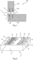
- Figure 1 shows a building section 100 according to the invention in a sectional view.
- the building section 100 comprises a floor plate 110, which could also be designed as a ceiling plate, a molded block 1 arranged on the floor plate 110 and a load-bearing concrete wall 120 arranged above the molded block 1.
- the view of the Figure 1 is in the longitudinal direction of this concrete wall 120.
- Both the base plate 110 and the load-bearing concrete wall 120 are reinforced with a reinforcement (not shown in detail) or reinforcement, which is arranged inside the floor slab and the building wall. From the building wall 120, vertically acting compressive forces D are transmitted through the form block 1, which are in Figure 2 indicated by an arrow, are transferred to the floor or ceiling plate 110.
- FIG. 1 illustrates several lead-through areas 10 extend in the mold body 2 of the mold block 1, such as Figure 1 illustrated, several tension elements 130.
- the implementation areas 10 are in Figure 2 shown.
- the tension elements 130 each extend from the base plate 110 through the molded block 1 to the vertically running building wall 120. Vertically directed tensile forces can be transferred by means of the tension elements 130 from the building wall 120 to the base plate 110 and in the opposite direction.
- the molded block 1 has a molded body 2 made of a mineral building material, such as a concrete material, wherein the concrete material is a non-heat-insulating concrete with a thermal conductivity ⁇ greater than 1.6 W/mK.
- the molded block 1 has a support surface 4 facing the floor slab 110 and a bearing surface 6 facing the building wall 120.
- the support surface 4 and the bearing surface 6 run essentially plane-parallel to one another.
- at least one insulating body 8 is arranged inside the molded body 2, which, as Figure 1 indicates, extends parallel between the contact surface 4 and the support surface 6.
- the insulating body 8 runs here into the plane of the drawing.
- a molded component 1 according to the invention is shown according to an embodiment, the molded body 2 of which has a substantially rectangular contact surface 4 and a likewise substantially rectangular support surface 6.
- the molded body 2 forms a base surface on the contact surface 4 and the support surface 6, which can also be referred to here as contact surfaces or connection areas, which is determined by the external dimensions of the molded body, in particular by its side lengths a and b.
- feedthrough areas 10 are provided on the molded body 2, which extend from the contact surface 4 to the support surface 6.
- the lead-through areas 10 designed as lead-through openings are designed to accommodate tension elements 130 ( Figure 1 ), namely a tension element 130 which extends through the respective lead-through area.
- the lead-through area 10 can have a clearance which is larger by a predetermined amount than the external dimensions, in particular the external diameter of the tension element 130.
- the resulting cavity between the wall surface of the lead-through area 10 and the surface of the tension element 130 can be filled with a casting compound (not shown) or other body.
- the cavity between the wall surface of the lead-through area 10 and the surface of the tension element 130 is filled completely and over the entire height of the molded body 2 from the contact surface 4 to the support surface 6.
- At least one transmission projection 12, 12' is arranged on the surface of the support surface 4 and/or the bearing surface 6.
- the transmission projection 12, 12' is designed as a type of profile element, which is preferably formed in one piece with the molded body 2.
- the transmission projections are used in particular to transmit shear forces acting between the building wall 120 and the floor or ceiling plate 110.
- a material layer 14, 14' made of an elastic material is provided at least in some areas on the first and/or second contact area.
- the material layers can cover only partial areas of the contact surface 4 and/or the support surface 6 or can completely cover the first and/or second contact area.
- At least one insulating body section 8 is arranged in the interior of the molded body 2.
- Figure 3 shows a further embodiment of a building section 100' according to the invention in a sectional view with a base plate 110, a molded block 1' arranged on the base plate 110 and a load-bearing building wall 120 arranged above the molded block 1'.
- the base plate 110 shown and the load-bearing building wall 120 made of concrete have a reinforcement or reinforcement (not shown in detail) inside the base plate 110 or the building wall 120.
- the molded block 1' comprises a molded body 2', via which vertically acting compressive forces D, similar to the molded body 2 in Fig.2 , from the building wall 120 into the floor slab 110.
- the floor slab 110 can be designed as a ceiling slab.
- this can mean that the floor slab 110 also functions as a ceiling slab, because it also closes off a floor as a ceiling slab and serves as a floor slab for the next floor.
- the Form module 1 according to Figure 1 or the mold block 1' according to Figure 3 on a building wall 120 and under the floor slab 110, which then forms a ceiling slab.
- tension elements 130 run through the lead-through areas 10' in the molded block 1'.
- the tension elements 130 extending from the floor or ceiling plate 110 through the molded block 1' to the vertically running building wall 120 are designed to transmit tensile forces acting in the vertical direction and hold the building parts 110, 120 arranged one above the other at a predetermined distance from one another.
- the molded block 1' can be in the molded body 2', similar to Fig.2 shown, have an insulating section or body 8.
- the molded body 2' of the molded block 1' is made of a mineral building material, namely a non-heat-insulating concrete.
- the molded body 2' has a contact surface 4 and a support surface 6, which run essentially parallel to one another and on each of which a substantially vertically projecting transfer projection 22, 22' is provided.
- At least one lead-through area 10' extends through the molded body 2' for the tension element.
- the transfer projection 22, 22' is formed in one piece with the molded body 2' as a type of profile element.
- the transfer projections 22, 22' have vertically running side surfaces or flanks 24, which in the Figure 5 shown embodiment are partially covered by a material layer 26 with elastic properties.
- the flat surface 16, 16' of the molded body 2' is not always covered by the elastic layer.
- the material layer 26 serves in particular in the longitudinal direction of a building wall 120 to be arranged on the molded block 1' to compensate for shear forces in the longitudinal or horizontal direction and enables a relative movement depending on the layer thickness between the building wall 120 and the floor or ceiling plate 110.
- An oblique flank can also be provided for the projection 22, 22', as shown in Figure 4 will be shown later, namely as transmission projection 12 or 12'.
- Figure 4 shows an exemplary embodiment of the molded body 2 on the contact surface 4 and/or the support surface 6.
- the contact surface 4 and/or the support surface 6 has transfer projections 12, 12' designed as profile elements and can be referred to as a toothed joint, with surfaces 16, 16' offset parallel to one another and flanks 18 running obliquely thereto.
- a positive connection between the Contact areas of the molded block and a floor or ceiling plate arranged above it or the building wall 120 The same or a different design can also be provided downwards.
- the surface of the contact area 4, 6 is covered with a material layer 20 with elastic properties, which in the embodiment shown has different layer thicknesses, which are, for example, in a range from 1 mm to about 20 mm.
- the surfaces 16 run to the side flanks 18 of the transfer projections 12, 12' at an obtuse angle ⁇ of about 91° to about 135°.
- an elastomer is used as the material layer 20, which is compressed when a force is applied and returns almost to its original shape after the force acting on the elastomer is removed.
- the layer thickness of the material layer 20 varies.
- the layer thickness on the surface 16' forming the base of the toothed joint is greater than the layer thickness on the oblique flank 18 formed as a tooth flank and greater than on the surface 16 forming a plateau of the toothed joint.
- the different layer sections of the material layer on the different surfaces/flanks 16, 16', 18 can have different elasticities or degrees of hardness.
- the transfer projection(s) 22 are designed as a type of cuboid-shaped material projection, which is formed in particular in one piece or integrally with the molded body.
- the transfer projection 22 has flanks 24 running essentially at right angles to the base surface of the contact surface 4 and/or the support surface 6. This provides a right angle (90°), whereas the Figure 4 shows an obtuse angle ⁇ .
- the right-angled arrangement enables a secure positive connection to be achieved between the molded component 1 and a floor or ceiling slab to be brought into contact with it or the building wall 120.
- the positive connection and the associated transmission of shear force can also be ensured if the building wall or the floor or ceiling slab move vertically to the contact area of the molded component 1.
- the vertical flank shape of the transfer projection 22 enables a permanent positive locking to be achieved.
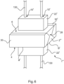
- Figure 6 shows a molded block 1" with a molded body 2" made of a concrete material, which has a substantially rectangular shape in the area of its contact surfaces 4, 6 to a respective floor slab or building wall.
- the molded body 2" has a material constriction 28 over its height in cross-section in at least one of its main longitudinal directions.
- the molded body 2" of the molded block 1" has, in particular in a cross-section running transversely to the long side a ⁇ , an outer contour which preferably tapers evenly from the contact area 4 to approximately the middle of the molded block, which preferably widens evenly again from the middle of the molded block to the contact area 6 of the molded block.
- the long sides a ⁇ of the molded body 2" thus have a type of wedge-shaped depression.
- the molded component 1" shown has two insulating body sections 30, 30' extending to both long sides a' of the molded body 2", which are connected to the surface areas of the wedge-shaped depressions on the molded body 2" or are inserted therein.
- the insulating body sections 30, 30' determine at least the external dimensions of the molded component 1" in the direction of its side length b.
- the insulating body sections 30, 30' have the same height as the molded body 2" between the two contact areas 4, 6.
- the insulating body sections are preferably made of an insulating foam, such as EPS, PUR or XPS.
- the molded component 1" shown further has, on its contact areas 4, 6 of the molded body 2", substantially vertically projecting transfer projections 22', which in the embodiment shown have a cuboid shape.
- the transfer projection has in the direction of the long side a ⁇ and in the direction of the long side b ⁇ of the mold block 1" has dimensions that are smaller than the dimensions of the mold body 2" at the level of the contact areas.
- the length of the transfer projection is to be understood as its dimension in the direction of or parallel to the long side a ⁇ of the mold block.
- the width of the transfer projection is to be understood as its dimension parallel to the long side b ⁇ of the mold block 1".
- the length of the transfer projection 22' has a ratio to the length of the mold block in the range between approximately 0.5 and 0.9.
- the width of the transfer projection 22' has a ratio to the width of the mold body 2" at the level of the contact areas in the range of approximately 0.3 to 0.8.
- the molded body 2" and the transfer projections 22' protruding from the contact areas 4, 6 have two feedthrough areas 10' for one tension element 130 each.
- the tension elements 130 are cast directly with the molded body 2" and the transfer projections 22'.
- the tension elements 130 are concreted into the molded body 2" and the transfer projections 22' protruding therefrom directly during the manufacture of the molded block, preferably using a concrete material.
Landscapes
- Physics & Mathematics (AREA)
- Engineering & Computer Science (AREA)
- Architecture (AREA)
- Acoustics & Sound (AREA)
- Electromagnetism (AREA)
- Civil Engineering (AREA)
- Structural Engineering (AREA)
- Building Environments (AREA)
- Panels For Use In Building Construction (AREA)
Priority Applications (1)
| Application Number | Priority Date | Filing Date | Title |
|---|---|---|---|
| EP24173256.9A EP4400668B1 (fr) | 2017-10-09 | 2017-10-09 | Élément moulé destiné à être placé entre un mur de construction et une plaque de sol ou de plafond, et section de construction pourvus d'un tel élément |
Applications Claiming Priority (2)
| Application Number | Priority Date | Filing Date | Title |
|---|---|---|---|
| EP17195439.9A EP3467221B1 (fr) | 2017-10-09 | 2017-10-09 | Élément moulé destiné à être placé entre un mur de construction et une plaque de sol ou de plafond, et section de construction pourvus d'un tel élément |
| EP24173256.9A EP4400668B1 (fr) | 2017-10-09 | 2017-10-09 | Élément moulé destiné à être placé entre un mur de construction et une plaque de sol ou de plafond, et section de construction pourvus d'un tel élément |
Related Parent Applications (2)
| Application Number | Title | Priority Date | Filing Date |
|---|---|---|---|
| EP17195439.9A Division EP3467221B1 (fr) | 2017-10-09 | 2017-10-09 | Élément moulé destiné à être placé entre un mur de construction et une plaque de sol ou de plafond, et section de construction pourvus d'un tel élément |
| EP17195439.9A Division-Into EP3467221B1 (fr) | 2017-10-09 | 2017-10-09 | Élément moulé destiné à être placé entre un mur de construction et une plaque de sol ou de plafond, et section de construction pourvus d'un tel élément |
Publications (3)
| Publication Number | Publication Date |
|---|---|
| EP4400668A2 true EP4400668A2 (fr) | 2024-07-17 |
| EP4400668A3 EP4400668A3 (fr) | 2024-08-07 |
| EP4400668B1 EP4400668B1 (fr) | 2026-04-08 |
Family
ID=60051404
Family Applications (2)
| Application Number | Title | Priority Date | Filing Date |
|---|---|---|---|
| EP24173256.9A Active EP4400668B1 (fr) | 2017-10-09 | 2017-10-09 | Élément moulé destiné à être placé entre un mur de construction et une plaque de sol ou de plafond, et section de construction pourvus d'un tel élément |
| EP17195439.9A Active EP3467221B1 (fr) | 2017-10-09 | 2017-10-09 | Élément moulé destiné à être placé entre un mur de construction et une plaque de sol ou de plafond, et section de construction pourvus d'un tel élément |
Family Applications After (1)
| Application Number | Title | Priority Date | Filing Date |
|---|---|---|---|
| EP17195439.9A Active EP3467221B1 (fr) | 2017-10-09 | 2017-10-09 | Élément moulé destiné à être placé entre un mur de construction et une plaque de sol ou de plafond, et section de construction pourvus d'un tel élément |
Country Status (2)
| Country | Link |
|---|---|
| EP (2) | EP4400668B1 (fr) |
| HU (1) | HUE067312T2 (fr) |
Families Citing this family (2)
| Publication number | Priority date | Publication date | Assignee | Title |
|---|---|---|---|---|
| AT522177B1 (de) * | 2019-06-17 | 2020-09-15 | Walter Eberl | Sockel für eine Holzwand |
| CN113356372B (zh) * | 2021-06-02 | 2022-11-04 | 新疆昌吉建设(集团)有限责任公司 | 一种装配式建筑用直角连接件 |
Citations (1)
| Publication number | Priority date | Publication date | Assignee | Title |
|---|---|---|---|---|
| EP2405065B1 (fr) | 2010-11-19 | 2014-04-23 | Georg Koch | Elément isolant de connexion pour supporter des charges de compression |
Family Cites Families (3)
| Publication number | Priority date | Publication date | Assignee | Title |
|---|---|---|---|---|
| CN2095896U (zh) * | 1991-03-09 | 1992-02-12 | 冯启文 | 榫式复合空心保温砌块 |
| DE10106222A1 (de) * | 2001-02-10 | 2002-08-14 | Schoeck Entwicklungsgmbh | Mauersteinförmiges Wärmedämmelement |
| EP3296476B1 (fr) * | 2016-09-16 | 2024-04-24 | Schöck Bauteile GmbH | Dispositif de liaison d'un mur de bâtiment à une dalle de sol ou de plafond et élément de moulage d'un tel système |
-
2017
- 2017-10-09 EP EP24173256.9A patent/EP4400668B1/fr active Active
- 2017-10-09 HU HUE17195439A patent/HUE067312T2/hu unknown
- 2017-10-09 EP EP17195439.9A patent/EP3467221B1/fr active Active
Patent Citations (1)
| Publication number | Priority date | Publication date | Assignee | Title |
|---|---|---|---|---|
| EP2405065B1 (fr) | 2010-11-19 | 2014-04-23 | Georg Koch | Elément isolant de connexion pour supporter des charges de compression |
Also Published As
| Publication number | Publication date |
|---|---|
| EP4400668A3 (fr) | 2024-08-07 |
| EP3467221C0 (fr) | 2024-07-03 |
| EP3467221A1 (fr) | 2019-04-10 |
| EP3467221B1 (fr) | 2024-07-03 |
| EP4400668B1 (fr) | 2026-04-08 |
| HUE067312T2 (hu) | 2024-10-28 |
Similar Documents
| Publication | Publication Date | Title |
|---|---|---|
| EP3690159B1 (fr) | Enveloppe de bâtiment et procédé d'isolement thermique des enveloppes de bâtiment en béton | |
| EP3085843B1 (fr) | Dispositif et procédé de couplage thermique de parties betonnées de bâtiment | |
| DE102010027661B4 (de) | Schalungsvorrichtung und Verfahren zum Schaffen einer Aussparung beim Gießen eines Gebäudebauteils | |
| EP2486196B1 (fr) | Procédé et dispositif pour l'ajout postérieur d'une partie extérieure en saillie à une partie de bâtiment existante | |
| AT513576B1 (de) | Wandschalungssystem sowie ein Verfahren zum Herstellen eines Wandschnitts mit einer Isolierschalung | |
| EP0059171A1 (fr) | Boulon et canon pour la prise et la transmission d'une force transversale | |
| WO2016037864A1 (fr) | Double mur en béton armé à haute résistance ou à très haute résistance | |
| WO2008092664A2 (fr) | Élément de construction | |
| EP3467223B1 (fr) | Élément moulé destiné à etre placé entre un mur de construction et une plaque de sol ou de plafond et section de construction pourvue d'un tel élément moulé | |
| EP3467221B1 (fr) | Élément moulé destiné à être placé entre un mur de construction et une plaque de sol ou de plafond, et section de construction pourvus d'un tel élément | |
| EP3296476B1 (fr) | Dispositif de liaison d'un mur de bâtiment à une dalle de sol ou de plafond et élément de moulage d'un tel système | |
| EP1482101A1 (fr) | Elément de construction, procédé pour fabriquer des éléments de construction et moyens de liaison pour élément de construction | |
| EP3754125B1 (fr) | Élément de construction pour le montage dans des joints de dilatation de bâtiments | |
| EP4086401B1 (fr) | Composant denté thermoisolant et procédé de construction d'une section de bâtiment | |
| EP3296478B1 (fr) | Dispositif de liaison d'un mur de bâtiment à une dalle de sol ou de plafond et élément de moulage d'un tel système | |
| EP3839162B1 (fr) | Composant thermo-isolant destiné à être utilisé dans une fente de séparation entre deux parties de construction | |
| EP3912778B1 (fr) | Procédé de fabrication à plat d'une pièce porteuse verticale préfabriquée en béton et pièce porteuse verticale préfabriquée en béton | |
| EP3467220B1 (fr) | Partie de bâtiment et procédé de fabrication d'une telle partie de bâtiment | |
| EP3663474A1 (fr) | Dispositif d'isolement thermique entre un mur de bâtiment bétonné et un plancher, ainsi que procédé de fabrication | |
| EP3663475B1 (fr) | Dispositif d'isolement thermique entre un mur de bâtiment bétonné et un plancher, ainsi que procédé de fabrication | |
| EP1528169A1 (fr) | Elément de construction pour la fixation ultérieure en particulier sur une partie d'un bâtiment | |
| DE20310430U1 (de) | Installationskanal | |
| EP3296477B1 (fr) | Élément de moulage pour disposer sur une dalle de sol ou sur ou sous une dalle de plafond et procédé de fabrication de l'élément de moulage | |
| EP3225759A1 (fr) | Élément de raccordement d'isolation thermique d'éléments de bâtiments verticaux reliés | |
| AT523024A1 (de) | Gebäudekonstruktion und Verfahren zur Bildung derselben |
Legal Events
| Date | Code | Title | Description |
|---|---|---|---|
| PUAI | Public reference made under article 153(3) epc to a published international application that has entered the european phase |
Free format text: ORIGINAL CODE: 0009012 |
|
| STAA | Information on the status of an ep patent application or granted ep patent |
Free format text: STATUS: THE APPLICATION HAS BEEN PUBLISHED |
|
| REG | Reference to a national code |
Free format text: PREVIOUS MAIN CLASS: E04C0001410000 Ref country code: DE Ref legal event code: R079 Ref document number: 502017017299 Country of ref document: DE Ipc: E04B0001780000 |
|
| PUAL | Search report despatched |
Free format text: ORIGINAL CODE: 0009013 |
|
| AC | Divisional application: reference to earlier application |
Ref document number: 3467221 Country of ref document: EP Kind code of ref document: P |
|
| AK | Designated contracting states |
Kind code of ref document: A2 Designated state(s): AL AT BE BG CH CY CZ DE DK EE ES FI FR GB GR HR HU IE IS IT LI LT LU LV MC MK MT NL NO PL PT RO RS SE SI SK SM TR |
|
| AK | Designated contracting states |
Kind code of ref document: A3 Designated state(s): AL AT BE BG CH CY CZ DE DK EE ES FI FR GB GR HR HU IE IS IT LI LT LU LV MC MK MT NL NO PL PT RO RS SE SI SK SM TR |
|
| RIC1 | Information provided on ipc code assigned before grant |
Ipc: E04B 1/76 20060101ALN20240701BHEP Ipc: E04C 1/41 20060101ALI20240701BHEP Ipc: E04B 1/78 20060101AFI20240701BHEP |
|
| STAA | Information on the status of an ep patent application or granted ep patent |
Free format text: STATUS: REQUEST FOR EXAMINATION WAS MADE |
|
| 17P | Request for examination filed |
Effective date: 20250207 |
|
| STAA | Information on the status of an ep patent application or granted ep patent |
Free format text: STATUS: EXAMINATION IS IN PROGRESS |
|
| 17Q | First examination report despatched |
Effective date: 20250404 |
|
| GRAP | Despatch of communication of intention to grant a patent |
Free format text: ORIGINAL CODE: EPIDOSNIGR1 |
|
| STAA | Information on the status of an ep patent application or granted ep patent |
Free format text: STATUS: GRANT OF PATENT IS INTENDED |
|
| RIC1 | Information provided on ipc code assigned before grant |
Ipc: E04B 1/78 20060101AFI20251013BHEP Ipc: E04C 1/41 20060101ALI20251013BHEP Ipc: E04B 1/76 20060101ALN20251013BHEP |
|
| INTG | Intention to grant announced |
Effective date: 20251104 |
|
| RIC1 | Information provided on ipc code assigned before grant |
Ipc: E04B 1/78 20060101AFI20251029BHEP Ipc: E04C 1/41 20060101ALI20251029BHEP Ipc: E04B 1/76 20060101ALN20251029BHEP |
|
| GRAS | Grant fee paid |
Free format text: ORIGINAL CODE: EPIDOSNIGR3 |
|
| GRAA | (expected) grant |
Free format text: ORIGINAL CODE: 0009210 |
|
| STAA | Information on the status of an ep patent application or granted ep patent |
Free format text: STATUS: THE PATENT HAS BEEN GRANTED |
|
| AC | Divisional application: reference to earlier application |
Ref document number: 3467221 Country of ref document: EP Kind code of ref document: P |
|
| AK | Designated contracting states |
Kind code of ref document: B1 Designated state(s): AL AT BE BG CH CY CZ DE DK EE ES FI FR GB GR HR HU IE IS IT LI LT LU LV MC MK MT NL NO PL PT RO RS SE SI SK SM TR |
|
| REG | Reference to a national code |
Ref country code: CH Ref legal event code: F10 Free format text: ST27 STATUS EVENT CODE: U-0-0-F10-F00 (AS PROVIDED BY THE NATIONAL OFFICE) Effective date: 20260408 Ref country code: GB Ref legal event code: FG4D Free format text: NOT ENGLISH |
|
| REG | Reference to a national code |
Ref country code: CH Ref legal event code: R17 Free format text: ST27 STATUS EVENT CODE: U-0-0-R10-R17 (AS PROVIDED BY THE NATIONAL OFFICE) Effective date: 20260409 |
|
| REG | Reference to a national code |
Ref country code: DE Ref legal event code: R096 Ref document number: 502017017299 Country of ref document: DE |