EP3086148A2 - Kupplungsanordnung zur nichtaxialen übertragung von elektromagnetischer strahlung - Google Patents
Kupplungsanordnung zur nichtaxialen übertragung von elektromagnetischer strahlung Download PDFInfo
- Publication number
- EP3086148A2 EP3086148A2 EP16168973.2A EP16168973A EP3086148A2 EP 3086148 A2 EP3086148 A2 EP 3086148A2 EP 16168973 A EP16168973 A EP 16168973A EP 3086148 A2 EP3086148 A2 EP 3086148A2
- Authority
- EP
- European Patent Office
- Prior art keywords
- fiber
- feeding
- target
- coupling arrangement
- core
- Prior art date
- Legal status (The legal status is an assumption and is not a legal conclusion. Google has not performed a legal analysis and makes no representation as to the accuracy of the status listed.)
- Granted
Links
Images


Classifications
-
- G—PHYSICS
- G02—OPTICS
- G02B—OPTICAL ELEMENTS, SYSTEMS OR APPARATUS
- G02B6/00—Light guides; Structural details of arrangements comprising light guides and other optical elements, e.g. couplings
- G02B6/24—Coupling light guides
- G02B6/26—Optical coupling means
- G02B6/28—Optical coupling means having data bus means, i.e. plural waveguides interconnected and providing an inherently bidirectional system by mixing and splitting signals
- G02B6/2804—Optical coupling means having data bus means, i.e. plural waveguides interconnected and providing an inherently bidirectional system by mixing and splitting signals forming multipart couplers without wavelength selective elements, e.g. "T" couplers, star couplers
- G02B6/2821—Optical coupling means having data bus means, i.e. plural waveguides interconnected and providing an inherently bidirectional system by mixing and splitting signals forming multipart couplers without wavelength selective elements, e.g. "T" couplers, star couplers using lateral coupling between contiguous fibres to split or combine optical signals
- G02B6/2835—Optical coupling means having data bus means, i.e. plural waveguides interconnected and providing an inherently bidirectional system by mixing and splitting signals forming multipart couplers without wavelength selective elements, e.g. "T" couplers, star couplers using lateral coupling between contiguous fibres to split or combine optical signals formed or shaped by thermal treatment, e.g. couplers
-
- Y—GENERAL TAGGING OF NEW TECHNOLOGICAL DEVELOPMENTS; GENERAL TAGGING OF CROSS-SECTIONAL TECHNOLOGIES SPANNING OVER SEVERAL SECTIONS OF THE IPC; TECHNICAL SUBJECTS COVERED BY FORMER USPC CROSS-REFERENCE ART COLLECTIONS [XRACs] AND DIGESTS
- Y10—TECHNICAL SUBJECTS COVERED BY FORMER USPC
- Y10T—TECHNICAL SUBJECTS COVERED BY FORMER US CLASSIFICATION
- Y10T29/00—Metal working
- Y10T29/49—Method of mechanical manufacture
- Y10T29/49002—Electrical device making
- Y10T29/49117—Conductor or circuit manufacturing
- Y10T29/49174—Assembling terminal to elongated conductor
Definitions
- the invention relates to coupling arrangements for non-axial transfer of electromagnetic radiation from at least one feeding fiber to a target fiber in a transfer region.
- this kind of coupling arrangement it is possible to couple multimode pump fibers, which in the following are referred to as feeding fibers, into the outer cladding of single-clad or multi-clad fibers, which in the following are called target fibers.
- Multimode optical fibers are used in many applications especially for delivering optical power.
- One of the most interesting applications is the so called fiber laser.
- the double-clad fiber (DCF) concept is mostly used.
- a DCF consists of a core to guide the laser light, surrounded by a cladding to guide the multi-mode pump light.
- Such a DCF which is one of the possible optical target fibers, comprises a core, which has a relatively small diameter of for example 5 to 60 ⁇ m. It has a numerical aperture, which for example can be in the range of 0.03 to 0.2.
- the cladding has a thickness of some 100 ⁇ m and a numerical aperture of for example in the range of 0.3 to 0.7.
- the core of such a double-clad fiber can be doped with a rare-earth element and in this case can serve as the active gain medium of the fiber laser.
- DCF double-clad fiber
- pump radiation has to be fed into the cladding of the DCF, the so called "target fiber”. But also in many other applications of these target fibers it is necessary to feed in electromagnetic radiation.
- Electromagnetic pump radiation can be fed into the target fiber through an end surface or through the lateral cladding surface by either a free beam of pump radiation or through feeding fibers.
- a free beam of pump radiation or through feeding fibers.
- From US 5,864,644 it is known to feed in the pump radiation by feeding fibers which are usually bundled together, drawn into a taper and fusion spliced to an end surface of the target fiber.
- a signal fiber has to be placed to feed in or out the laser light.
- This technique is known as Tapered Fused Fiber Bundle (TFB) technique.
- TFB Tapered Fused Fiber Bundle
- This technique has two major disadvantages. The first disadvantage is the splice between the tapered fibers and the target fiber, where the fibers to be connected have to be aligned very exactly.
- a small misalignment can lead to a strong degradation of the beam quality of the laser.
- the second disadvantage is the tapering process of the feeding fibers and the signal fiber to match the optical requirements of the core and the cladding of the target fiber.
- a small taper mismatch can lead to a significant thermal load of the fiber coupler and also to a strong degradation of the beam quality of the laser.
- Another disadvantage is that due to existence of only two target fiber end surfaces the number of pump feeding fibers is limited. Thus, the laser power can not be simply scaled up by using more pump diodes.
- the cladding surface is the lateral surface of the target fiber extending in longitudinal direction of the target fiber.
- the feeding of pump radiation through the cladding surface is called non-axial transfer.
- usually at least one feeding fiber is fused to the target fiber such that the cladding surfaces of both the feeding fiber and the target fiber are in optical contact with each other.
- feeding fibers having a converging taper portion This means the diameter and thus the size of the cross-section of the respective fiber is progressively reduced.
- Using a converging taper portion of the feeding fiber is known from US 5,999,673 and US 7,933,479 B2 .
- the numerical aperture of the feeding fiber should be smaller than or equal to the numerical aperture of the target fiber.
- the relevant numerical aperture is the one of the outmost layer, guiding the multi-mode pump light, of the respective fiber.
- this usually is the core of the feeding fiber.
- This unfortunately in practice is rather difficult, since in many cases both the core and the cladding consist of almost the same material differing only by some doping elements.
- the cladding material is often glass in order to be able to transport high radiation power through the feeding fiber and the fiber can easier withstand the deleterious effects of high temperature and humidity encountered during operation.
- the taper-ratio is the ratio of the diameter of the feeding fiber at the beginning of the converging taper portion and the diameter of the feeding fiber at the end of the converging taper portion.
- a taper-ratio of 4 means, the diameter of the feeding fiber is reduced in the converging taper portion to one forth of the original value.
- Increasing the taper-ratio leads to a better transfer of electromagnetic radiation from the feeding fiber into the target fiber but reduced the mechanical stability of the coupling arrangement.
- a coupling arrangement as described above is usually manufactured by mounting the involved fibers in a mechanical mount and twisting the at least one feeding fiber around the target fiber.
- the converging taper portion and the diverging taper portion are generated by heating of the twisted fibers. Since the fibers touch each other during the twisting, the feeding fibers get fused to the target fiber.
- the target fiber also shows a converging taper portion and a diverging taper portion after an arbitrary longitudinal irreversible extension, leading to changed optical characteristics of the fiber.
- US 7,933,479 B2 it is known from US 7,933,479 B2 to perform a pre-tapering of the feeding fibers.
- the feeding fibers are heated and subjected to a force applied in longitudinal direction before they are mounted in the mechanical mount and twisted around the target fiber.
- the feeding fibers then comprise a converging taper portion and a diverging taper portion when they are mounted and thus, the extension in longitudinal direction of the twisted fibers can be reduced leading to a reduced tapering of the target fiber.
- the disadvantage is that the pre-tapered feeding fiber becomes very damageable due to the reduced diameter.
- a coupling arrangement comprises a target fiber, at least one feeding fiber and an intermediate fiber.
- the intermediate fiber comprises an input end and a converging taper portion, wherein the input end of the intermediate fiber is spliced to an output end of the feeding fiber in an axial way. Due to this coupling electromagnetic radiation being fed through the feeding fiber enters the intermediate fiber through its input end surface.
- the converging taper portion of the intermediate fiber is fused to the target fiber in the transfer region in a non-axial way. This leads to a non-axial coupling such that electromagnetic radiation, which entered the intermediate fiber through the input end surface thereof, is coupled into the target fiber.
- the feeding fiber can comprise a core and a cladding. It might also be a coreless fiber. In this case the use of an intermediate filter can be advantageous particularly if the cross sections of the feeding fiber and the intermediate fiber are different.
- the target fiber can be a single or multi clad fiber.
- the core can be single- or multi-mode, depending on the respective application in which the target fiber is needed.
- the target fiber can be passive or active, depending on the dopants in the core of the target fiber.
- the target fiber can also be a polarization maintaining or a non-polarization maintaining fiber.
- the intermediate fiber has a cross-section which should be large enough to cover the full cross-section of the core of the feeding fiber.
- the cross-section is as small as possible to fulfill this requirement. It is nevertheless possible to choose intermediate fibers having a larger cross-section.
- the intermediate fiber is usually a coreless fiber, which means that an intermediate fiber comprises a cladding and preferably an easily removable polymer coating but no additional core, made from a material that differs from the cladding material by some dopants.
- the feeding fiber can for example have one or more claddings, an arbitrary diameter and an arbitrary numerical aperture.
- the feeding fiber is connected to the intermediate fiber for example in a thermal way, i.e. by micro gas flame, plasma source, electrical filament or laser source.
- the intermediate fiber has a non-circular cross-section such as a polygonal, in particular a hexagonal or octagonal cross-section.
- the intermediate fiber further comprises a diverging taper portion, adjacent to the converging taper portion.
- the intermediate fiber is not fused to the target fiber at its diverging taper portion such that there is a gap between said target fiber and the diverging taper portion of the intermediate fiber.
- Pump radiation which has entered the intermediate fiber through the input end surface and is not transferred into the target fiber stays in the intermediate fiber and is led away from the target fiber through the diverging taper portion of the intermediate fiber.
- a gap is provided between the target fiber and the diverging taper portion of the intermediate fiber. This also leads to a higher transfer efficiency and thus to a smaller power loss.
- the coupling arrangement comprises a transfer region.
- the target fiber comprises a core and at least one cladding.
- the target fiber is formed by an adapted fiber having an adapted fiber core and at least one adapted fiber cladding, wherein the adapted fiber core of the adapted fiber has a mode field diameter, which at least partially is larger than the mode field diameter of the target fiber outside the transfer region.
- the mode field diameter of the adapted fiber core at the beginning and the end of the transfer region is larger than the mode field diameter of the adapted fiber core in a centre portion of the transfer region, while the mode field diameter of the adapted fiber core in the centre portion of the transfer region is at least as large as mode field diameter of the core of the target fiber outside the transfer region.
- a coupling arrangement of this embodiment can for example be manufactured by cutting the target fiber at a particular position, thereby generating two cutting surfaces.
- the adapted fiber is then inserted by splicing its two ends to the respective cutting surfaces.
- electromagnetic radiation travelling through the core of the target fiber enters the adapted fiber at a first cutting surface, travels through the adapted fiber core of the adapted fiber and re-enters the original core of the target fiber at the second cutting surface.
- a mode field matching technique can be used, such as for example thermal diffusion of the dopants.
- the original target fiber with the inserted adapted fiber is called target fiber in the following.
- the transfer region can also be located at the beginning of the target fiber.
- the target fiber can be cut at a certain position, again leading to two cutting surfaces.
- an adapted fiber is then inserted between these to cutting surfaces.
- the target fiber can again be cut at one of the cutting surfaces.
- the target fiber begins with the adapted fiber which is still with one end spliced to the remaining cutting surface, such that light entering the adapted fiber from the feeding or the intermediate fiber travels through this cutting surface into the target fiber.
- the stretching leads to a tapering of the target fiber in particular in the region of the adapted fiber.
- the adapted fiber originally comprises an adapted fiber core with a larger mode field diameter than the mode field diameter of the original target fiber.
- the mode field diameter of the adapted fiber in the centre portion of the transfer region is at least as large as the diameter of the core of the target fiber outside the transfer region, which is the mode field diameter of the core of the original target fiber. Due to the insertion of this special kind of adapted fiber the negative effects of the tapering of the target fiber get strongly reduced.
- the feeding fiber or an intermediate fiber, which is spliced to an output end of the feeding fiber is fused to the target fiber in the transfer region in a non-axial way.
- the feeding fiber of the intermediate fiber is fused to the adapted fiber which forms the target fiber in the transfer region.
- the preferred embodiments of the intermediate fiber which have been described earlier are also preferred when the intermediate fiber is fused to the adapted fiber instead of the original target fiber.
- the core and/or the cladding of the original target fiber are made from the same material as the adapted fiber core and/or the adapted fiber cladding of the adapted fiber, respectively. This ensures an optimal contact between the two fibers, leading to an optimal transfer of radiation from the original target fiber into the adapted fiber and back into the target fiber.
- the feeding fiber comprises an input end to be connected to a light source, such as a laser diode, and an opposing final end.
- the feeding fiber or an intermediate fiber, which is spliced to the final end of the feeding fiber comprises a converging taper portion, which is fused to the target fiber in a non-axial way.
- a mirror element is located at the final end of the feeding fiber or said intermediate fiber.
- a diverging taper portion is located at the final end of the respective fiber and the end of the converging taper portion.
- Electromagnetic radiation that comes from the light source, such as the laser diode, and that is not transferred into the target fiber, stays in the feeding fiber or the intermediate fiber and reaches the final end thereof.
- the ratio of forward to backward travelling light is adjustable by changing the taper-ratio of the feeding fiber or the intermediate fiber, respectively.
- a pump light stripper can be located at the final end of the intermediate fiber or the feeding fiber. Usually, a small part of the electromagnetic radiation is reflected at the final surface of the final end of the respective fiber even if no mirror element is provided. This can be prevented by using a pump light stripper.
- the target fiber is formed by an adapted fiber in order to reduce the negative effects of the tapering of the target fiber in the transfer region as described above.
- the preferred embodiments of the adapted fiber are also preferred in the embodiments of the invention described here. This refers especially to the relations between the mode field diameter of the adapted fiber core of the adapted fiber and the mode field diameter of the core of the original target fiber.
- a mode mixing element is located between the converging taper portion of the feeding fiber or the intermediate fiber and the mirror element.
- One reason for an electromagnetic radiation not to be transferred into the target fiber is that the radiation has a too small numerical aperture. This will not be changed when the respective radiation is reflected at the mirror element.
- the mode mixing element is provided. This leads to an increased probability that the radiation will be transferred into the target fiber after being reflected at the mirror element.
- the intermediate fiber comprises an input end to be connected to the feeding fiber, as already described, and an opposing final end with a mirror element.
- this intermediate fiber as the feeding fiber described above can be fused to either an unchanged target fiber or to the adapted as described above.
- the at least one feeding fiber has a non-circular cross-section.
- the shape of the cross-section can for example be polygonal, such as hexagonal or octagonal. Of course, every other non-circular cross-section is possible, such as for example an irregular shape.
- the coupling arrangement comprises more than one feeding fiber. Through more than one feeding fiber more power and electromagnetic radiation can be transferred into the target fiber.
- the coupling arrangement comprises an even number of feeding fibers.
- the coupling arrangement has more than four, in particular six feeding fibers or intermediate fibers, respectively. Preferably every feeding fiber is connected to an intermediate fiber as described above.
- a method for manufacturing a coupling arrangement as described above comprises the following steps:
- the intermediate fiber is spliced at the output end of the feeding fiber before it is mounted in the mechanical mount.
- a mirror element and/or a mode mixing element are used. These elements should be integrated in the feeding fiber or the intermediate fiber, respectively, before the respective fiber is mounted in the mechanical mount. It is also possible to mount the feeding fiber in one position and to mount the intermediate fiber in the second position.
- the adapted fiber has also to be connected to the original target fiber before the target fiber is mounted in the mechanical mount.
- these fibers In order to achieve a tapering of the respective fibers these fibers have to be heated. This is done after twisting the feeding fibers or the intermediate fibers around the target fiber. Hence, also the tapering takes place after the feeding fibers or the intermediate fibers have been twisted around the target fiber. In this step the fibers also get fused to each other.
- the first force, which is applied to the feeding fiber, or if used, to the intermediate fiber is different from the second force, which is applied to the target fiber, it is possible to reach different tapering and different taper-ratios of the different fibers.
- the target fiber is not twisted in step b. of the previously described method. This reduces mechanical tension of the target fiber, which can have negative effects on the optical characteristics of the fiber.
- an external heat source is used. This means, that the heat from the heat source is provided from the outside of the respective fibers. Since at the outside of the fiber bundle the intermediate fibers or the feeding fibers are located these fibers are closer to the heat source and thus become warmer. Hence, these fibers become more malleable than the target fiber in the center of the fiber bundle. The same force applied to the target fiber and the intermediate or feeding fiber leads to a stronger tapering of the intermediate or feeding fiber. Usually the target fibre has a larger diameter than the feeding fiber or the intermediate fiber, which also leads to this effect.
- the feeding fiber or the intermediate fiber is pre-tapered before it is mounted in the mechanical mount.
- the pre-tapering comprises the steps of heating the respective fiber and applying a taper-force in longitudinal direction to the heated fiber. This leads to an elongation of the heated fiber and thus to a reduction of the diameter and to a tapered region.
- the mount used to apply the taper-force to the feeding fiber or the intermediate fiber is the same mount, which is used to apply the first force to the feeding fiber or the intermediate fiber.
- the pre-tapered fiber does not have to be moved into a new mount. Since the mechanical stability of the pre-tapered fiber is reduced compared to the non-tapered fiber, this is a big advantage.
- each of these embodiments and methods can be used and configured using more than one feeding fiber and more than one intermediate fiber. It is for example possible to use more than one feeding fiber and to provide each or just some of them with an intermediate fiber, a mirror element and/or a mode mixing element. It is of course also possible to pre-taper all or some of the feeding fibers or intermediate fibers before mounting them in the mechanical mount.
- Fig.1a to 1d show different steps of a method according to one embodiment of the present invention.
- Fig. 1a shows a feeding fiber 2 with an output end 4, which is connected with an intermediate fiber 6.
- the intermediate fiber 6 is fusion spliced to the output end 4 of the feeding fiber 2 with its input end 8.
- Schematically a heat source 10 is shown, which can for example be a micro gas flame, a plasma source, a filament source or a laser.
- the heat source 10 is used to heat the intermediate fiber 6 until a given temperature is reached.
- the heat source 10 can move along the longitudinal position of the intermediate fiber 6, which is to be heated. By the length of this movement the length of the converging taper portion can be adjusted.
- the heat source 10 moves along the intermediate fiber 6 with a certain frequency in a back and forth movement. This can be achieved by moving the heat source 10 or by moving a mount of the intermediate fiber or using a combination of both movements. Then a taper-force is applied to the intermediate fiber 6, which is denoted by the double arrow 12 in Fig. 1 b. As is shown in Fig. 1 b a diameter of the intermediate fiber 6 is reduced in a taper portion 14 leading to a converging taper portion 16 and a diverging taper portion 18. During the application of the taper-force the heat source 10 can still be used to heat the intermediate fiber 16, in order to keep it soft enough to be stretched and tapered.
- Fig. 1c shows a target fiber 20 and four intermediate fibers 6. Every intermediate fiber 6 is connected to a respective feeding fiber 2.
- the feeding fiber 2 and the target fiber 20 are both mounted in a mechanical mount. This comprises a first mount 22 and a second mount 24. On the left side in Fig. 1c the first mount 22 is shown.
- the target fiber 20 and the feeding fiber 2 are both mounted in this first mount 22 and are thus fixed relative to one another at this position.
- the second mount 24 has separate fixtures for the target fiber 20 and the intermediate fibers 6.
- the fixture for the intermediate fibers 6 can for example have a circular shape in order to provide for a three-dimensional ordering of the different fibers.
- the fixture for the intermediate fibers 6 allows for a rotation relative to the fixture for the target fiber 20, which is denoted by the rotation arrow 26 in Fig. 1c . This rotation leads to the twisting of the intermediate fibers 6 around the target fiber 20, which is shown in Fig. 1 c. After the twisting the different fibers touch each other and get fused to each other since the heat source 10 is used to heat the different fibers.
- the target fiber 20 and the intermediate fibers 6 are mounted in different fixtures, that together form the second mount 24, it is possible to apply different forces to the different kinds of fibers.
- the intermediate fibers 6 are subjected to a first force 28, while the target fiber is subjected to a second force 30. Both the first force 28 and the second force 30 are applied in longitudinal direction and are denoted by arrows in Fig. 1c .
- the first force 28 should be chosen strong enough to get a strongly tapered intermediate fiber 6.
- the second force 30 should be chosen just strong enough to keep the target fiber 20 in a longitudinal straight position without extending or tapering the target fiber 20 too much.
- heating and applying the force the fixture of the target fiber 20 allows for a rotation of the target fiber 20 around its longitudinal axis.
- Fig. 1d shows, how the fibers are anchored and housed after cooling.
- the target fiber 20 and the four feeding fibers 2 are anchored in a first anchoring bond 32, while on the other side of the transfer region, which is the region, in which the different fibers touch, the target fiber 20 and the intermediate fibers 6 are anchored in a second anchoring bond 34.
- the coupling arrangement is then covered by a housing 36 to keep the coupling arrangement dust-free and to protect it from mechanical shocks and the like.
- the housing 36 is only schematically shown in form of a dotted line.
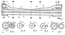
- Fig. 2 shows a schematic longitudinal cross section of a coupling arrangement according to one embodiment of the present invention.
- the target fiber 20 comprises a core 38 in which the signal radiation is transported or amplified.
- the core 38 is surrounded by a cladding 40, in which the pump radiation is transported or absorbed.
- the target fiber 20 also comprises a coating 42, which is removed in the centre part of Fig. 2 . This part is the so called transfer region.
- the feeding fiber 2 is shown, which also comprises a core 44, a cladding 46 and a coating 48.
- the intermediate fiber 6 without its coating 50 is fusion spliced to the feeding fiber 2 such that it connects to the core 44 of the feeding fiber 2. Electromagnetic radiation travelling through the feeding fiber 2 can thus enter the intermediate fiber 6.
- the outer cladding surface of the intermediate fiber 6 touches the cladding 40 of the target fiber 20.
- the intermediate fiber 6 comprises the converging taper portion 16, with which it is fused to the target fiber 20.
- the intermediate fiber 6 Adjacent to the converging taper portion 16 the intermediate fiber 6 has a diverging taper portion 18. As is shown in Fig. 2 this diverging taper portion 18 does not touch the cladding 40 of the target fiber 20. Instead there is a gap 52 between the two fibers. This prevents radiation, which has already been transferred from the intermediate fiber 6 into the target fiber 20 to be re-transferred into the intermediate fiber 6. In the right part of Fig. 2 both fibers 20, 6 comprise a coating and do not touch anymore. In the intermediate fiber 6, the electromagnetic radiation, which has not been transferred into the target fiber 20, is led away from the coupling arrangement.
- Fig 3a shows a schematic transversal cross-section along the line A-A in Fig. 2 .
- Fig. 3a one can clearly distinguish the two cores 38, 44, the two claddings 40, 46 and the two coatings 42, 48 of the target fiber 20 and the feeding fiber 2, respectively.
- the two coatings 42, 48 touch but no transfer or electromagnetic radiation is possible.
- Fig. 3b shows the cross section along line B-B in Fig. 2 .
- the target fiber 20 does not have a coating, but simply consists of the core 38 and the cladding 40.
- the intermediate fiber 6 does not comprise its coating 50 in the transfer region and already touches the cladding 40 of the target fiber 20.
- the diameter of the intermediate fiber 6 in Fig 3b corresponds to the diameter of the core 44 of the feeding fiber 2.
- the cross section of the intermediate fiber 6 can also be larger than the cross section of the core 44 of the feeding fiber 2.
- Fig 3b does not show the converging taper portion 16 of the intermediate fiber 6. Nevertheless a transfer of radiation from the intermediate fiber 6 into the target fiber 20 is possible.
- Fig. 3c shows the cross section along line C-C in Fig. 2 . Again the target fiber 20 and the intermediate fiber 6 are shown. The diameter of the intermediate fiber 6 is much smaller than the one shown in Fig. 3b . Between the lines B-B and C-C in Fig. 2 is the converging taper portion 16. This is the region where the main transfer of radiation takes place.
- Fig. 3d shows the cross section along line D-D in Fig. 2 .
- the diameter of the intermediate fiber 6 has increased again due to the diverging taper portion 18.
- the gap 52 that prevents any radiation from being transferred from one fiber to another one.
- Fig. 3e shows the cross section along line E-E in Fig. 2 .
- Both fibers comprise a coating and do not touch anymore. A transfer of radiation is clearly impossible.
- the intermediate fiber 6 shown in Fig. 2, 3b to 3e has a circular cross section. This is not necessary for the invention to work.
- the cross section is non-circular such as polygonal for example. This means of course not a mathematically polygonal cross section but a cross section that is polygonal within the manufacturing limits.
- Today, fibers having non-circular and even polygonal cross section are commercially available. These standards referring to the shape of the cross section of the respective fiber are also to be applied here.
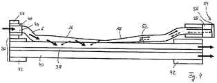
- Fig. 4 shows basically the same situation as Fig. 2 .
- Electromagnetic radiation to be transferred into the target fiber 20 enters Fig. 4 from the left through the feeding fiber 2. It then enters the intermediate fiber 6, which is spliced to an output end 4 of the feeding fiber 2.
- the intermediate fiber 6 comprises a converging taper portion 16. In this region the electromagnetic radiation gets transferred into the target fiber 20. Adjacent to the converging taper portion 16 there is a diverging taper portion 18 which is separated from the target fiber 20 by the gap 52. Through this part of the intermediate fiber 6 a certain portion of the radiation is transported.
- At a final end 54 of the intermediate fiber 6 there is a mirror element 56 at which the radiation gets reflected and sent back through the intermediate fiber 6.
- a mode mixing element 58 is positioned in front of the mirror element 56 . This mode mixing element 58 changes the numerical aperture of the radiation. This leads to a higher probability that the radiation after being reflected by the mirror element 56 is transferred into the target fiber 20.
- the way of the radiation in the first direction, i.e. from left to right in Fig. 4 is denoted by full arrows, while the way of the radiation in the second direction after being reflected by the mirror element 56, i.e. from right to left in Fig. 4 is denoted by dashed arrows.
- the thickness of the respective arrows denotes the amount of radiation and the respective power in each direction, without being true to scale. This means that in the first direction a larger amount of electromagnetic radiation is transferred into the target fiber than in the second direction. Possible losses of electromagnetic radiation are not taken into account. Also the exact position of the transfer of the respective radiation is not meant to be shown by the position of the respective arrows.
- Fig. 5 shows a schematic view on a coupling arrangement according to another embodiment of the present invention. It shows a target fiber 20 and two feeding fibers 2. At the output ends 4 of both feeding fibers 2 an intermediate fiber 6 is spliced to the feeding fiber 2.
- the target fiber 20 comprises two cutting surfaces 60, at which the original target fiber 20 has been cut in order to insert an adapted fiber 62.
- the target fiber 20 in the right and the left part of Fig. 5 comprises a core 38 and a cladding 40 and a coating 42.
- the adapted fiber 62 comprises an adapted fiber core 64 and an adapted fiber cladding 66.
- the adapted fiber core 64 of the adapted fiber 62 has a larger diameter, which in the schematic also means a larger mode field diameter than the core 38 of the target fiber 20 in the left and the right part of Fig. 5 .
- the adapted fiber 62 also gets tapered.
Landscapes
- Physics & Mathematics (AREA)
- General Physics & Mathematics (AREA)
- Optics & Photonics (AREA)
- Optical Couplings Of Light Guides (AREA)
- Mechanical Coupling Of Light Guides (AREA)
Applications Claiming Priority (2)
| Application Number | Priority Date | Filing Date | Title |
|---|---|---|---|
| US13/354,475 US9097853B2 (en) | 2012-01-20 | 2012-01-20 | Coupling arrangement for non-axial transfer of electromagnetic radiation |
| EP12008440.5A EP2618191B1 (de) | 2012-01-20 | 2012-12-19 | Kopplungsanordnung zur nichtaxialen Übertragung von elektromagnetischer Strahlung |
Related Parent Applications (1)
| Application Number | Title | Priority Date | Filing Date |
|---|---|---|---|
| EP12008440.5A Division EP2618191B1 (de) | 2012-01-20 | 2012-12-19 | Kopplungsanordnung zur nichtaxialen Übertragung von elektromagnetischer Strahlung |
Publications (3)
| Publication Number | Publication Date |
|---|---|
| EP3086148A2 true EP3086148A2 (de) | 2016-10-26 |
| EP3086148A3 EP3086148A3 (de) | 2017-01-18 |
| EP3086148B1 EP3086148B1 (de) | 2019-03-27 |
Family
ID=47678446
Family Applications (2)
| Application Number | Title | Priority Date | Filing Date |
|---|---|---|---|
| EP12008440.5A Active EP2618191B1 (de) | 2012-01-20 | 2012-12-19 | Kopplungsanordnung zur nichtaxialen Übertragung von elektromagnetischer Strahlung |
| EP16168973.2A Active EP3086148B1 (de) | 2012-01-20 | 2012-12-19 | Kupplungsanordnung zur nichtaxialen übertragung von elektromagnetischer strahlung |
Family Applications Before (1)
| Application Number | Title | Priority Date | Filing Date |
|---|---|---|---|
| EP12008440.5A Active EP2618191B1 (de) | 2012-01-20 | 2012-12-19 | Kopplungsanordnung zur nichtaxialen Übertragung von elektromagnetischer Strahlung |
Country Status (3)
| Country | Link |
|---|---|
| US (1) | US9097853B2 (de) |
| EP (2) | EP2618191B1 (de) |
| DK (1) | DK2618191T3 (de) |
Families Citing this family (4)
| Publication number | Priority date | Publication date | Assignee | Title |
|---|---|---|---|---|
| AU2014211965B2 (en) * | 2013-02-01 | 2018-04-26 | Polyvalor, Limited Partnership | Asymmetric optical fiber coupler |
| CN107017551A (zh) * | 2017-05-27 | 2017-08-04 | 中国工程物理研究院应用电子学研究所 | 一种(2+1)×1侧面融锥型光纤泵浦合束器的封装方法 |
| FR3139955B1 (fr) | 2022-09-19 | 2025-10-31 | Compagnie Ind Des Lasers Cilas | Amplificateur laser fibré comprenant un dispositif de pompe latérale. |
| TWI871038B (zh) * | 2023-10-03 | 2025-01-21 | 財團法人工業技術研究院 | 耦光模組及其製作方法 |
Citations (3)
| Publication number | Priority date | Publication date | Assignee | Title |
|---|---|---|---|---|
| US5864644A (en) | 1997-07-21 | 1999-01-26 | Lucent Technologies Inc. | Tapered fiber bundles for coupling light into and out of cladding-pumped fiber devices |
| US5999673A (en) | 1994-12-28 | 1999-12-07 | Italtel Spa | Coupling arrangement between a multi-mode light source and an optical fiber through an intermediate optical fiber length |
| US7933479B2 (en) | 2006-02-07 | 2011-04-26 | Itf Laboratories Inc. | Multimode fiber outer cladding coupler for multi-clad fibers |
Family Cites Families (16)
| Publication number | Priority date | Publication date | Assignee | Title |
|---|---|---|---|---|
| GB2238396B (en) * | 1989-11-17 | 1993-09-15 | Stc Plc | Optical waveguide tapers |
| US5195151A (en) * | 1990-12-17 | 1993-03-16 | Aster Corporation | Optical fiber couplers and methods of their manufacture |
| DE4214766A1 (de) * | 1992-05-04 | 1993-11-11 | Sel Alcatel Ag | Faseroptischer Verstärker mit rückwirkungsunempfindlichem Pumplaser |
| FR2727769B1 (fr) | 1994-12-02 | 1997-01-10 | Alcatel Cable | Procede de couplage entre une fibre optique multicoeurs et plusieurs fibres optiques monocoeurs |
| FR2811437A1 (fr) | 2000-07-06 | 2002-01-11 | Cit Alcatel | Fibre optique a pompage par la gaine et procede de fabrication d'une telle fibre |
| US6493492B1 (en) | 2000-08-28 | 2002-12-10 | Lucent Technologies Inc. | Fiber bundle and optical amplifier |
| US7046432B2 (en) * | 2003-02-11 | 2006-05-16 | Coherent, Inc. | Optical fiber coupling arrangement |
| EP1639679B1 (de) | 2003-06-16 | 2008-07-02 | Soreq Nuclear Research Center | Optische vorrichtung |
| US7046875B2 (en) * | 2003-10-29 | 2006-05-16 | Itf Technologies Optiques Inc. | Optical coupler comprising multimode fibers and method of making the same |
| US7016573B2 (en) * | 2003-11-13 | 2006-03-21 | Imra America, Inc. | Optical fiber pump multiplexer |
| FI125571B (en) * | 2005-02-23 | 2015-11-30 | Liekki Oy | A bundle of optical fibers and a process for making it |
| CN101283491A (zh) * | 2005-07-08 | 2008-10-08 | 晶体纤维公司 | 光耦器件及其制造和使用方法 |
| GB2439345A (en) * | 2006-06-23 | 2007-12-27 | Gsi Group Ltd | Annular tapered fibre coupler for cladding pumping of an optical fibre |
| US7593435B2 (en) | 2007-10-09 | 2009-09-22 | Ipg Photonics Corporation | Powerful fiber laser system |
| WO2009077636A1 (en) * | 2007-12-14 | 2009-06-25 | Corelase Oy | Means of coupling light into optical fibers and methods of manufacturing a coupler |
| DE102008020828A1 (de) | 2008-04-25 | 2009-10-29 | Jt Optical Engine Gmbh + Co. Kg | Faserkoppler |
-
2012
- 2012-01-20 US US13/354,475 patent/US9097853B2/en active Active
- 2012-12-19 EP EP12008440.5A patent/EP2618191B1/de active Active
- 2012-12-19 DK DK12008440.5T patent/DK2618191T3/en active
- 2012-12-19 EP EP16168973.2A patent/EP3086148B1/de active Active
Patent Citations (3)
| Publication number | Priority date | Publication date | Assignee | Title |
|---|---|---|---|---|
| US5999673A (en) | 1994-12-28 | 1999-12-07 | Italtel Spa | Coupling arrangement between a multi-mode light source and an optical fiber through an intermediate optical fiber length |
| US5864644A (en) | 1997-07-21 | 1999-01-26 | Lucent Technologies Inc. | Tapered fiber bundles for coupling light into and out of cladding-pumped fiber devices |
| US7933479B2 (en) | 2006-02-07 | 2011-04-26 | Itf Laboratories Inc. | Multimode fiber outer cladding coupler for multi-clad fibers |
Also Published As
| Publication number | Publication date |
|---|---|
| US9097853B2 (en) | 2015-08-04 |
| EP2618191A2 (de) | 2013-07-24 |
| EP2618191A3 (de) | 2014-07-09 |
| DK2618191T3 (en) | 2016-08-22 |
| EP3086148B1 (de) | 2019-03-27 |
| EP3086148A3 (de) | 2017-01-18 |
| EP2618191B1 (de) | 2016-05-11 |
| US20130188911A1 (en) | 2013-07-25 |
Similar Documents
| Publication | Publication Date | Title |
|---|---|---|
| US10761271B2 (en) | Polarization maintaining optical fiber array | |
| US6990278B2 (en) | Mode multiplexing optical coupling device | |
| JP5782104B2 (ja) | マルチコアファイバへの低損失でモードフィールドが整合された結合のための方法、および装置 | |
| EP2033277B1 (de) | Vorrichtung für die ankopplung von strahlung in oder aus einer optischen faser | |
| US8040926B2 (en) | Multi-core fiber for optical pumping device and manufacturing method thereof, optical pumping device, fiber laser and fiber amplifier | |
| US7933479B2 (en) | Multimode fiber outer cladding coupler for multi-clad fibers | |
| JP5768090B2 (ja) | マルチコアファイバ用ファンイン/ファンアウトデバイス | |
| US20090154881A1 (en) | Optical Fiber Combiner and Method of Manufacturing Thereof | |
| EP3850408B1 (de) | Durch einen mantellichtabstreifer eingekapselte glasfaserspleissung | |
| US20130273240A1 (en) | Optical Mode Conversion Using Intermodal Cherenkov Radiation | |
| EP3086148B1 (de) | Kupplungsanordnung zur nichtaxialen übertragung von elektromagnetischer strahlung | |
| US7203397B2 (en) | Polarization maintaining optical fiber coupler and method of manufacturing same | |
| US10603744B2 (en) | Aiming beam side-coupler | |
| RU2638906C2 (ru) | Способ вытягивания высокоэффективного сдвоенного лазерного волокна и полученное по нему волокно | |
| US20080298746A1 (en) | Optical Fiber Side Coupler for Coupling Light Between a Multimode Optical Fiber and a Cladding Pumping Optical Fiber | |
| WO2004083921A1 (en) | Optical fibre and method of launching pump power into a fibre, and a manufacturing method | |
| US12085759B2 (en) | Method of coupling optical fibers, and optical coupler | |
| US8511914B2 (en) | Method for connecting optical fibers and connection structure of optical fibers | |
| CZ305868B6 (cs) | Přizpůsobovací člen profilu pole signálové větve slučovačů signálu a čerpání, slučovač a optické zařízení |
Legal Events
| Date | Code | Title | Description |
|---|---|---|---|
| PUAI | Public reference made under article 153(3) epc to a published international application that has entered the european phase |
Free format text: ORIGINAL CODE: 0009012 |
|
| AC | Divisional application: reference to earlier application |
Ref document number: 2618191 Country of ref document: EP Kind code of ref document: P |
|
| AK | Designated contracting states |
Kind code of ref document: A2 Designated state(s): AL AT BE BG CH CY CZ DE DK EE ES FI FR GB GR HR HU IE IS IT LI LT LU LV MC MK MT NL NO PL PT RO RS SE SI SK SM TR |
|
| PUAL | Search report despatched |
Free format text: ORIGINAL CODE: 0009013 |
|
| AK | Designated contracting states |
Kind code of ref document: A3 Designated state(s): AL AT BE BG CH CY CZ DE DK EE ES FI FR GB GR HR HU IE IS IT LI LT LU LV MC MK MT NL NO PL PT RO RS SE SI SK SM TR |
|
| RIC1 | Information provided on ipc code assigned before grant |
Ipc: G02B 6/28 20060101AFI20161212BHEP Ipc: H01S 3/094 20060101ALI20161212BHEP |
|
| STAA | Information on the status of an ep patent application or granted ep patent |
Free format text: STATUS: REQUEST FOR EXAMINATION WAS MADE |
|
| 17P | Request for examination filed |
Effective date: 20170704 |
|
| RBV | Designated contracting states (corrected) |
Designated state(s): AL AT BE BG CH CY CZ DE DK EE ES FI FR GB GR HR HU IE IS IT LI LT LU LV MC MK MT NL NO PL PT RO RS SE SI SK SM TR |
|
| STAA | Information on the status of an ep patent application or granted ep patent |
Free format text: STATUS: EXAMINATION IS IN PROGRESS |
|
| 17Q | First examination report despatched |
Effective date: 20180215 |
|
| GRAP | Despatch of communication of intention to grant a patent |
Free format text: ORIGINAL CODE: EPIDOSNIGR1 |
|
| STAA | Information on the status of an ep patent application or granted ep patent |
Free format text: STATUS: GRANT OF PATENT IS INTENDED |
|
| INTG | Intention to grant announced |
Effective date: 20181011 |
|
| GRAJ | Information related to disapproval of communication of intention to grant by the applicant or resumption of examination proceedings by the epo deleted |
Free format text: ORIGINAL CODE: EPIDOSDIGR1 |
|
| STAA | Information on the status of an ep patent application or granted ep patent |
Free format text: STATUS: EXAMINATION IS IN PROGRESS |
|
| GRAP | Despatch of communication of intention to grant a patent |
Free format text: ORIGINAL CODE: EPIDOSNIGR1 |
|
| STAA | Information on the status of an ep patent application or granted ep patent |
Free format text: STATUS: GRANT OF PATENT IS INTENDED |
|
| GRAS | Grant fee paid |
Free format text: ORIGINAL CODE: EPIDOSNIGR3 |
|
| INTC | Intention to grant announced (deleted) | ||
| GRAA | (expected) grant |
Free format text: ORIGINAL CODE: 0009210 |
|
| STAA | Information on the status of an ep patent application or granted ep patent |
Free format text: STATUS: THE PATENT HAS BEEN GRANTED |
|
| INTG | Intention to grant announced |
Effective date: 20190207 |
|
| AC | Divisional application: reference to earlier application |
Ref document number: 2618191 Country of ref document: EP Kind code of ref document: P |
|
| AK | Designated contracting states |
Kind code of ref document: B1 Designated state(s): AL AT BE BG CH CY CZ DE DK EE ES FI FR GB GR HR HU IE IS IT LI LT LU LV MC MK MT NL NO PL PT RO RS SE SI SK SM TR |
|
| REG | Reference to a national code |
Ref country code: GB Ref legal event code: FG4D |
|
| REG | Reference to a national code |
Ref country code: CH Ref legal event code: EP |
|
| REG | Reference to a national code |
Ref country code: AT Ref legal event code: REF Ref document number: 1113769 Country of ref document: AT Kind code of ref document: T Effective date: 20190415 |
|
| REG | Reference to a national code |
Ref country code: IE Ref legal event code: FG4D |
|
| REG | Reference to a national code |
Ref country code: DE Ref legal event code: R096 Ref document number: 602012058446 Country of ref document: DE |
|
| PG25 | Lapsed in a contracting state [announced via postgrant information from national office to epo] |
Ref country code: FI Free format text: LAPSE BECAUSE OF FAILURE TO SUBMIT A TRANSLATION OF THE DESCRIPTION OR TO PAY THE FEE WITHIN THE PRESCRIBED TIME-LIMIT Effective date: 20190327 Ref country code: NO Free format text: LAPSE BECAUSE OF FAILURE TO SUBMIT A TRANSLATION OF THE DESCRIPTION OR TO PAY THE FEE WITHIN THE PRESCRIBED TIME-LIMIT Effective date: 20190627 Ref country code: SE Free format text: LAPSE BECAUSE OF FAILURE TO SUBMIT A TRANSLATION OF THE DESCRIPTION OR TO PAY THE FEE WITHIN THE PRESCRIBED TIME-LIMIT Effective date: 20190327 Ref country code: LT Free format text: LAPSE BECAUSE OF FAILURE TO SUBMIT A TRANSLATION OF THE DESCRIPTION OR TO PAY THE FEE WITHIN THE PRESCRIBED TIME-LIMIT Effective date: 20190327 |
|
| REG | Reference to a national code |
Ref country code: NL Ref legal event code: MP Effective date: 20190327 |
|
| PG25 | Lapsed in a contracting state [announced via postgrant information from national office to epo] |
Ref country code: RS Free format text: LAPSE BECAUSE OF FAILURE TO SUBMIT A TRANSLATION OF THE DESCRIPTION OR TO PAY THE FEE WITHIN THE PRESCRIBED TIME-LIMIT Effective date: 20190327 Ref country code: HR Free format text: LAPSE BECAUSE OF FAILURE TO SUBMIT A TRANSLATION OF THE DESCRIPTION OR TO PAY THE FEE WITHIN THE PRESCRIBED TIME-LIMIT Effective date: 20190327 Ref country code: NL Free format text: LAPSE BECAUSE OF FAILURE TO SUBMIT A TRANSLATION OF THE DESCRIPTION OR TO PAY THE FEE WITHIN THE PRESCRIBED TIME-LIMIT Effective date: 20190327 Ref country code: BG Free format text: LAPSE BECAUSE OF FAILURE TO SUBMIT A TRANSLATION OF THE DESCRIPTION OR TO PAY THE FEE WITHIN THE PRESCRIBED TIME-LIMIT Effective date: 20190627 Ref country code: GR Free format text: LAPSE BECAUSE OF FAILURE TO SUBMIT A TRANSLATION OF THE DESCRIPTION OR TO PAY THE FEE WITHIN THE PRESCRIBED TIME-LIMIT Effective date: 20190628 Ref country code: LV Free format text: LAPSE BECAUSE OF FAILURE TO SUBMIT A TRANSLATION OF THE DESCRIPTION OR TO PAY THE FEE WITHIN THE PRESCRIBED TIME-LIMIT Effective date: 20190327 |
|
| REG | Reference to a national code |
Ref country code: AT Ref legal event code: MK05 Ref document number: 1113769 Country of ref document: AT Kind code of ref document: T Effective date: 20190327 |
|
| PG25 | Lapsed in a contracting state [announced via postgrant information from national office to epo] |
Ref country code: EE Free format text: LAPSE BECAUSE OF FAILURE TO SUBMIT A TRANSLATION OF THE DESCRIPTION OR TO PAY THE FEE WITHIN THE PRESCRIBED TIME-LIMIT Effective date: 20190327 Ref country code: IT Free format text: LAPSE BECAUSE OF FAILURE TO SUBMIT A TRANSLATION OF THE DESCRIPTION OR TO PAY THE FEE WITHIN THE PRESCRIBED TIME-LIMIT Effective date: 20190327 Ref country code: SK Free format text: LAPSE BECAUSE OF FAILURE TO SUBMIT A TRANSLATION OF THE DESCRIPTION OR TO PAY THE FEE WITHIN THE PRESCRIBED TIME-LIMIT Effective date: 20190327 Ref country code: AL Free format text: LAPSE BECAUSE OF FAILURE TO SUBMIT A TRANSLATION OF THE DESCRIPTION OR TO PAY THE FEE WITHIN THE PRESCRIBED TIME-LIMIT Effective date: 20190327 Ref country code: PT Free format text: LAPSE BECAUSE OF FAILURE TO SUBMIT A TRANSLATION OF THE DESCRIPTION OR TO PAY THE FEE WITHIN THE PRESCRIBED TIME-LIMIT Effective date: 20190727 Ref country code: RO Free format text: LAPSE BECAUSE OF FAILURE TO SUBMIT A TRANSLATION OF THE DESCRIPTION OR TO PAY THE FEE WITHIN THE PRESCRIBED TIME-LIMIT Effective date: 20190327 Ref country code: CZ Free format text: LAPSE BECAUSE OF FAILURE TO SUBMIT A TRANSLATION OF THE DESCRIPTION OR TO PAY THE FEE WITHIN THE PRESCRIBED TIME-LIMIT Effective date: 20190327 Ref country code: ES Free format text: LAPSE BECAUSE OF FAILURE TO SUBMIT A TRANSLATION OF THE DESCRIPTION OR TO PAY THE FEE WITHIN THE PRESCRIBED TIME-LIMIT Effective date: 20190327 |
|
| PG25 | Lapsed in a contracting state [announced via postgrant information from national office to epo] |
Ref country code: SM Free format text: LAPSE BECAUSE OF FAILURE TO SUBMIT A TRANSLATION OF THE DESCRIPTION OR TO PAY THE FEE WITHIN THE PRESCRIBED TIME-LIMIT Effective date: 20190327 Ref country code: PL Free format text: LAPSE BECAUSE OF FAILURE TO SUBMIT A TRANSLATION OF THE DESCRIPTION OR TO PAY THE FEE WITHIN THE PRESCRIBED TIME-LIMIT Effective date: 20190327 |
|
| PG25 | Lapsed in a contracting state [announced via postgrant information from national office to epo] |
Ref country code: AT Free format text: LAPSE BECAUSE OF FAILURE TO SUBMIT A TRANSLATION OF THE DESCRIPTION OR TO PAY THE FEE WITHIN THE PRESCRIBED TIME-LIMIT Effective date: 20190327 Ref country code: IS Free format text: LAPSE BECAUSE OF FAILURE TO SUBMIT A TRANSLATION OF THE DESCRIPTION OR TO PAY THE FEE WITHIN THE PRESCRIBED TIME-LIMIT Effective date: 20190727 |
|
| REG | Reference to a national code |
Ref country code: DE Ref legal event code: R097 Ref document number: 602012058446 Country of ref document: DE |
|
| PG25 | Lapsed in a contracting state [announced via postgrant information from national office to epo] |
Ref country code: DK Free format text: LAPSE BECAUSE OF FAILURE TO SUBMIT A TRANSLATION OF THE DESCRIPTION OR TO PAY THE FEE WITHIN THE PRESCRIBED TIME-LIMIT Effective date: 20190327 |
|
| PLBE | No opposition filed within time limit |
Free format text: ORIGINAL CODE: 0009261 |
|
| STAA | Information on the status of an ep patent application or granted ep patent |
Free format text: STATUS: NO OPPOSITION FILED WITHIN TIME LIMIT |
|
| PG25 | Lapsed in a contracting state [announced via postgrant information from national office to epo] |
Ref country code: SI Free format text: LAPSE BECAUSE OF FAILURE TO SUBMIT A TRANSLATION OF THE DESCRIPTION OR TO PAY THE FEE WITHIN THE PRESCRIBED TIME-LIMIT Effective date: 20190327 |
|
| 26N | No opposition filed |
Effective date: 20200103 |
|
| PG25 | Lapsed in a contracting state [announced via postgrant information from national office to epo] |
Ref country code: TR Free format text: LAPSE BECAUSE OF FAILURE TO SUBMIT A TRANSLATION OF THE DESCRIPTION OR TO PAY THE FEE WITHIN THE PRESCRIBED TIME-LIMIT Effective date: 20190327 |
|
| REG | Reference to a national code |
Ref country code: CH Ref legal event code: PL |
|
| REG | Reference to a national code |
Ref country code: BE Ref legal event code: MM Effective date: 20191231 |
|
| PG25 | Lapsed in a contracting state [announced via postgrant information from national office to epo] |
Ref country code: MC Free format text: LAPSE BECAUSE OF FAILURE TO SUBMIT A TRANSLATION OF THE DESCRIPTION OR TO PAY THE FEE WITHIN THE PRESCRIBED TIME-LIMIT Effective date: 20190327 |
|
| PG25 | Lapsed in a contracting state [announced via postgrant information from national office to epo] |
Ref country code: IE Free format text: LAPSE BECAUSE OF NON-PAYMENT OF DUE FEES Effective date: 20191219 Ref country code: LU Free format text: LAPSE BECAUSE OF NON-PAYMENT OF DUE FEES Effective date: 20191219 |
|
| PG25 | Lapsed in a contracting state [announced via postgrant information from national office to epo] |
Ref country code: LI Free format text: LAPSE BECAUSE OF NON-PAYMENT OF DUE FEES Effective date: 20191231 Ref country code: CH Free format text: LAPSE BECAUSE OF NON-PAYMENT OF DUE FEES Effective date: 20191231 Ref country code: BE Free format text: LAPSE BECAUSE OF NON-PAYMENT OF DUE FEES Effective date: 20191231 |
|
| PG25 | Lapsed in a contracting state [announced via postgrant information from national office to epo] |
Ref country code: CY Free format text: LAPSE BECAUSE OF FAILURE TO SUBMIT A TRANSLATION OF THE DESCRIPTION OR TO PAY THE FEE WITHIN THE PRESCRIBED TIME-LIMIT Effective date: 20190327 |
|
| PG25 | Lapsed in a contracting state [announced via postgrant information from national office to epo] |
Ref country code: MT Free format text: LAPSE BECAUSE OF FAILURE TO SUBMIT A TRANSLATION OF THE DESCRIPTION OR TO PAY THE FEE WITHIN THE PRESCRIBED TIME-LIMIT Effective date: 20190327 Ref country code: HU Free format text: LAPSE BECAUSE OF FAILURE TO SUBMIT A TRANSLATION OF THE DESCRIPTION OR TO PAY THE FEE WITHIN THE PRESCRIBED TIME-LIMIT; INVALID AB INITIO Effective date: 20121219 |
|
| PG25 | Lapsed in a contracting state [announced via postgrant information from national office to epo] |
Ref country code: MK Free format text: LAPSE BECAUSE OF FAILURE TO SUBMIT A TRANSLATION OF THE DESCRIPTION OR TO PAY THE FEE WITHIN THE PRESCRIBED TIME-LIMIT Effective date: 20190327 |
|
| PGFP | Annual fee paid to national office [announced via postgrant information from national office to epo] |
Ref country code: GB Payment date: 20221222 Year of fee payment: 11 Ref country code: FR Payment date: 20221219 Year of fee payment: 11 |
|
| P01 | Opt-out of the competence of the unified patent court (upc) registered |
Effective date: 20230609 |
|
| GBPC | Gb: european patent ceased through non-payment of renewal fee |
Effective date: 20231219 |
|
| PG25 | Lapsed in a contracting state [announced via postgrant information from national office to epo] |
Ref country code: GB Free format text: LAPSE BECAUSE OF NON-PAYMENT OF DUE FEES Effective date: 20231219 |
|
| PG25 | Lapsed in a contracting state [announced via postgrant information from national office to epo] |
Ref country code: FR Free format text: LAPSE BECAUSE OF NON-PAYMENT OF DUE FEES Effective date: 20231231 |
|
| PG25 | Lapsed in a contracting state [announced via postgrant information from national office to epo] |
Ref country code: GB Free format text: LAPSE BECAUSE OF NON-PAYMENT OF DUE FEES Effective date: 20231219 Ref country code: FR Free format text: LAPSE BECAUSE OF NON-PAYMENT OF DUE FEES Effective date: 20231231 |
|
| PGFP | Annual fee paid to national office [announced via postgrant information from national office to epo] |
Ref country code: DE Payment date: 20251215 Year of fee payment: 14 |