EP3086448A1 - Dispositif de mise à la terre pour machine électrique et procédés d'assemblage de celui-ci - Google Patents
Dispositif de mise à la terre pour machine électrique et procédés d'assemblage de celui-ci Download PDFInfo
- Publication number
- EP3086448A1 EP3086448A1 EP16166472.7A EP16166472A EP3086448A1 EP 3086448 A1 EP3086448 A1 EP 3086448A1 EP 16166472 A EP16166472 A EP 16166472A EP 3086448 A1 EP3086448 A1 EP 3086448A1
- Authority
- EP
- European Patent Office
- Prior art keywords
- core
- grounding device
- electric machine
- conductive fibers
- accordance
- Prior art date
- Legal status (The legal status is an assumption and is not a legal conclusion. Google has not performed a legal analysis and makes no representation as to the accuracy of the status listed.)
- Granted
Links
Images


Classifications
-
- H—ELECTRICITY
- H02—GENERATION; CONVERSION OR DISTRIBUTION OF ELECTRIC POWER
- H02K—DYNAMO-ELECTRIC MACHINES
- H02K11/00—Structural association of dynamo-electric machines with electric components or with devices for shielding, monitoring or protection
- H02K11/40—Structural association with grounding devices
-
- H—ELECTRICITY
- H02—GENERATION; CONVERSION OR DISTRIBUTION OF ELECTRIC POWER
- H02K—DYNAMO-ELECTRIC MACHINES
- H02K15/00—Processes or apparatus specially adapted for manufacturing, assembling, maintaining or repairing of dynamo-electric machines
Definitions
- the field of the invention relates generally to grounding devices and, more particularly, to grounding devices for electric machines having stray electrostatic charges on a rotatable shaft.
- At least some known electric machines such as brushless alternating current (BLAC) permanent magnet motors, are driven by pulse width modulation (PWM) technology and create a capacitance charge between the coils and the rotor. This capacitance charge results in substantially induced currents in the motor shaft.
- PWM pulse width modulation
- variable speed drives that induce a voltage or electrostatic charge on the motor shaft.
- Some variable speed drives utilize pulse width modulation technology to vary the speed of AC motors, which allows use of less expensive AC motors in applications where more expensive DC motors are used.
- a drawback of the use of AC motors with variable speed drives is that higher common mode voltage (CMV) is generated by the variable speed drive, which may increase induced currents on the shaft.
- CMV common mode voltage
- the technologies include conductive bearing grease, insulating the bearings, and using various brushes made of metal or other materials to ground the shaft.
- Such brushes are typically mounted in rigid holders and may be expensive and require lengthy installation procedures.
- the brushes are mounted to the exterior of the motor and therefore exposed to the environment surrounding the motor.
- a grounding device for an electric machine having a rotating component and a stationary component includes a core and a plurality of conductive fibers coupled to the core and extending therefrom.
- the plurality of conductive fibers are configured to electrically couple the rotating component with the stationary component such that an electrostatic charge on the rotating component is directed through the plurality of conductive fibers to the stationary component.
- an electric machine in another aspect, includes a rotating component, a stationary component coupled to a ground, and a grounding device conductively coupled between the rotating component and the stationary component.
- the grounding device includes a core and a plurality of conductive fibers coupled to the core and extending therefrom.
- the plurality of conductive fibers are configured to electrically couple the rotating component with the stationary component such that an electrostatic charge on the rotating component is directed through the plurality of conductive fibers to the stationary component.
- a method of assembling an electric machine includes providing a rotating component, coupling a stationary component to a ground, and positioning a grounding device between the rotating component and the stationary component.
- the grounding device includes a core and a plurality of conductive fibers coupled to the core and extending therefrom. At least a portion of the plurality of conductive fibers are configured to electrically couple the rotating component with the stationary component such that an electrostatic charge on the rotating component is directed through the plurality of conductive fibers to the stationary component.
- Grounding devices may be used to bleed the electrostatic charge to a ground.
- One such grounding device includes a core and a plurality of conductive fibers coupled to the core such that the fibers extend therefrom.
- the plurality of conductive fibers are configured to electrically couple the rotating component with a stationary component of the electric machine such that the electrostatic charge on the rotating component is directed through the plurality of conductive fibers, to the stationary component, and to the ground.
- the grounding device described herein substantially prevents bearing arcing and increases the service lifetime of the electric machine.
- FIG. 1 is a cross-sectional side view of an exemplary electric machine 10 that may be operated as either a generator or a motor.
- FIG. 2 is an exploded view of selected components of electric machine 10.
- electric machine 10 is coupled to a fan or centrifugal blower (not shown) for moving air through an air handling system, for blowing air over cooling coils, and/or for driving a compressor within an air conditioning/refrigeration system.
- a fan or centrifugal blower (not shown) for moving air through an air handling system, for blowing air over cooling coils, and/or for driving a compressor within an air conditioning/refrigeration system.
- HVAC heating, ventilation, and air conditioning
- machine 10 is used in fluid pumping applications.
- Machine 10 may also be used in commercial and industrial applications and/or hermetic compressor motors used in air conditioning applications, where machine 10 has a rating of greater than 1 hp. Although described herein in the context of an air handling system, electric machine 10 may engage any suitable work component and be configured to drive such a work component.
- Electric machine 10 includes a first end 12, a second end 14, and an assembly housing 16. Electric machine 10 also includes a stationary assembly 18 and a rotatable assembly 20. Assembly housing 16 defines an interior 22 and an exterior 24 of machine 10 and is configured to at least partially enclose and protect stationary assembly 18 and rotatable assembly 20.
- Stationary assembly 18 includes a stator core 28, which includes a plurality of teeth 30 and a plurality of windings 32 wound around stator teeth 30.
- stationary assembly 18 is a three-phase stator assembly and stator core 28 is formed from a stack of laminations made of highly magnetically permeable material.
- stationary assembly 18 is solid and/or is a single phase stator assembly.
- Stationary assembly 18 is one of a round, segmented, soft magnetic composite, or roll-up type stator construction and windings 32 are wound on stator core 28 in any suitable manner that enables machine 10 to function as described herein.
- Rotatable assembly includes a permanent magnet rotor core 36, having a plurality of permanent magnets 38, and a shaft 40 supported by a first bearing 42 and a second bearing 44. Bearings 42 and 44 are separated by a spring mechanism 46. In the exemplary embodiment, bearings 42 and 44 and spring mechanism 46 are housed in a counter-bore 23 formed in housing 16 and substantially circumscribe shaft 40.
- rotor core 36 is formed from a stack of laminations made of magnetically permeable material.
- rotor core 36 is a solid core. Rotor core 36 is substantially received in a central bore of stator core 28 for rotation along an axis of rotation X.
- FIG. 1 illustrates rotor core 36 and stator core 28 as solid for simplicity. While FIG. 1 is an illustration of a three-phase electric machine, the methods and apparatus described herein may be included within machines having any number of phases.
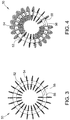
- FIG. 3 is a top view of an exemplary grounding device 50 that may be used with electric machine 10 (shown in FIG. 1 ).
- FIG. 4 is a perspective view of grounding device 50.
- grounding device 50 positioned about shaft 40 and generally includes a core 52 and a plurality of semi-conductive or conductive fibers 54 extending therefrom.
- grounding device 50 is rotatably stationary and in conductive contact with and/or grounded to a non-rotating component of electric machine 10, such as housing 16.
- grounding device 50 contacts any non-rotating component of machine 10 that enables grounding device 50 to function as described herein.
- grounding device 50 may be positioned to a machine bracket (not shown), machine foot (not shown), bearing bore (not shown), machine frame (not shown), spring 46, and/or stator core 28.
- core 52 includes a first end 56 and a second end 58 and is formed from an electrically conductive wire.
- core 52 is fabricated from steel, copper, brass, and/or other metals.
- core 52 is fabricated from an electrically non-conductive material, such as, but not limited to, plastic.
- core 52 is formed from any suitable material that enables grounding device 50 to function as defined herein.
- core 52 is fabricated from a formable material and is curved to form a loop such that ends 56 and 58 are coupled together.
- core 52 is a continuously-formed circular ring that does not include ends 56 and 58.
- grounding device 50 is shown as a substantially circular loop in the accompanying figures, it is understood that grounding device 50 may also be arc-shaped, that is, only a portion of a circle. Additionally, grounding device 50 may include one or more arc-shaped segments or substantially spherical elements. Generally, grounding device 50 has any shape that enables usage as described herein.
- fibers 54 are electrically conductive fibers that relay current build up from a rotating portion of machine 10 to a ground.
- fibers 54 are fabricated from steel, copper, brass, and/or other metals.
- fibers 54 are fabricated from a non-conductive material and include a conductive coating, such as carbon fiber or copper.
- fibers 54 are fabricated from any suitable flexible, electrically conductive or semi-conductive material that enables grounding device 50 to function as described herein.
- fibers 54 are fabricated from copper and/or carbon fiber.
- fibers 54 are spirally wound on core 52 and may have any suitable length. Alternatively, fibers 54 are coupled to core 52 in any suitable pattern that enables grounding device 50 to function as defined herein. In the exemplary embodiment, fibers 54 extend approximately 360° about core 52. In an alternative embodiment, fibers 54 extend approximately 180° about core 52. In yet another alternative embodiment, fibers 54 extend between approximately 60° and approximately 90° about core 52. However, fibers 54 may extend about core 52 in any suitable pattern that enables grounding device 50 to function as described herein.
- grounding device 50 is positioned about shaft 40 in counter-bore 23 within housing interior 22 such that grounding device 50 is contained within electric machine 10 and is not exposed to the surrounding environment. As such, grounding device 50 is not exposed to moisture or particulate matter (dust, dirt, debris) that may reduce the service lifetime of grounding device 50. More specifically, grounding device 50 is positioned between bearings 42 and 44 and substantially radially inward of spring mechanism 46. Grounding device 50 is positioned such that at least a portion of the plurality of fibers 54 contact both shaft 40 and housing 16. Specifically, at least a portion of fibers 54, such as fibers 54 on a radially outward portion of grounding device 50, extend through, and contact, spring mechanism 46 and also contact housing 16.
- grounding device 50 is positioned about shaft 40 such that at least a portion of the plurality of fibers 54 are within a close proximity of shaft 40 such that an electrostatic charge on shaft 40 can be electrically discharged to fibers 54 (i.e., fibers 54 are electrically coupled to shaft 40, but not in direct contact with shaft 40).
- fibers 54 are in contact with any rotating component of electric machine 10.
- fibers 54 may contact a surface of rotor core 36, rotor end rings (not shown), and/or a fan or hub (not shown) mounted to shaft 40.
- grounding device 50 is positionable within electric machine 10 in any suitable location that enables grounding device 50 to bleed an electric charge from a rotating component to a grounding component.
- an electrostatic charge is produced on a rotating component of electric machine, such as shaft 40.
- Grounding device 50 is positioned within counter-bore 23 such that fibers 54 contact shaft 40.
- Electrically conductive fibers 54 facilitate bleeding the electrostatic charge from shaft 40, through fibers 54, and to housing 16.
- Housing 16 one of serves as the ground or is electrically coupled to a ground and effectively transfers the electrostatic charge out of electric machine 10 to the ground.
- fibers 54 proximate shaft 40 on a radially inner portion of grounding device 50, conduct the electrostatic charge from shaft 40 and transfers the charge into fibers 54 proximate housing 16, on a radially outer portion of grounding device.
- the plurality of conductive fibers 54 are operable to both conduct the electrostatic charge away from the rotating component of electric machine 10, and to ground the charge by contacting a stationary component of electric machine 10. Furthermore, because at least one of fibers 54 contacts both spring mechanism 46 and housing 16, the electrostatic charge is grounded through both of these components. As such, grounding device 50 grounds the electrostatic charge from shaft 40 through the plurality of conductive fibers 54 rather than through core 52. In embodiments where core 52 is electrically conductive, at least a portion of the electrostatic charge is conducted through core 52 between the radially inner fibers 54 and radially outer fibers 54. In embodiments where core 52 is electrically non-conductive, the electrostatic charge travels through only fibers 54 to transfer the charge into housing 16.
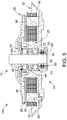
- FIG. 5 is a cross-sectional side view of another suitable embodiment of an electric machine 100 having grounding device 50
- FIG. 6 is an exploded view of electric machine 100.
- Electric machine 100 is substantially similar to electric machine 10 (shown in FIG. 1 ) in operation and composition, with the exception that electric machine 100 does not include a shaft and grounding device 50 is positioned proximate the second end 14 of machine 100 outward from bearings 42 and 44. As such, grounding device 50 is not positioned between bearings 42 and 44 in electrical machine 100.
- grounding device 50 positioned outward from bearings 42 and 44, such that bearings 42 and 44 are between grounding device 50 and rotating assembly 20, grounding device 50 may also be positioned inward of bearings 42 and 44 such that bearings 42 and 44 are positioned between grounding device 50 and stationary assembly 18.
- grounding device 50 contacts one bearing 42 ( FIG. 5 ) or both bearings 42 and 44 ( FIG. 1 ). Alternatively, grounding device 50 does not contact either of bearings 42 or 44.
- electric machine 100 also includes a dust cap 102 coupled to housing 16 at second end 14. Dust cap 102 prevents or at least substantially reduces an amount of particulate matter and moisture from entering housing interior 22 and collecting proximate grounding device 50.
- FIG. 7 is a cross-sectional side view of another suitable embodiment of an electric machine 200 having a grounding device 150
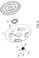
- FIG. 8 is an exploded view of selected components of electric machine 200.
- Electric machine 200 is substantially similar to electric machine 100 (shown in FIG. 5 ) in operation and composition, with the exception that electric machine 200 includes only a single bearing 42 and no spring mechanism.
- grounding device 150 is positioned within a central opening 202 defined by rotor core 36.
- grounding device 150 includes an eye 152, a core 154 extending from eye 152, and a plurality of fibers 156 extending from an end of core 154.
- Core 154 and fibers 156 are both formed from an electrically conductive material.
- core 154 and fibers 156 are fabricated from steel, copper, brass, and/or other metals.
- core 154 and fibers 156 are fabricated from a non-conductive material and include a conductive coating, such as carbon fiber or copper.
- fibers 156 are fabricated from any suitable flexible, electrically conductive or semi-conductive material that enables grounding device 150 to function as described herein. In the embodiment shown in FIGS.
- core 154 includes a first portion 160 coupled to housing 16 and a second portion 162 that extends into central opening 202 such that portions 160 and 162 are perpendicular to each other. Fibers 156 extend from second portion 162 within opening 202.
- a fastener 158 is used to couple grounding device 150 to an exterior surface 204 of housing 16.
- surface 204 includes a groove 206 that receives at least one of eye 152 and first portion 160 of core 154. Fibers 156 extend perpendicularly from second portion 162 of core 154 into central opening 202 of rotor core 36. Similar to electric machine 100, electric machine 200 also includes a dust cap 208 that substantially covers opening 202.
- an electrostatic charge is produced on a rotating component of electric machine 200, such as rotor core 36.
- Grounding device 150 is positioned within electric machine 200 such that fibers 156 contact the portion of rotor core 36 that forms central opening 202. Electrically conductive fibers 156 facilitate bleeding the electrostatic charge from rotor core 36 into housing 16. Housing 16 may be electrically coupled to a ground and effectively transfers the electrostatic charge out of electric machine 10 to the ground.
- the grounding device for an electric machine having a rotating component and a stationary component.
- the grounding device includes a core and a plurality of conductive fibers coupled to the core and extending therefrom.
- the plurality of conductive fibers are configured to electrically couple the rotating component with the stationary component such that an electrostatic charge on the rotating component is directed through the plurality of conductive fibers to the stationary component.
- the core and the plurality of conductive fibers are coupled between a pair of bearings and radially inward of a spring mechanism such that at least one conductive fiber of the plurality of conductive fibers extends through the spring mechanism and is electrically coupled with a stationary component.
- the core comprises a first portion coupled to the stationary component and a second portion positioned within an opening defined by the rotating component.
- the plurality of conductive fibers are coupled to the second portion.
- the plurality of conductive fibers are at least one of acrylic fibers, copper fibers, and carbon fibers.
- the plurality of conductive fibers comprise a conductive copper coating.
- the core is fabricated from an electrically conductive material, such as, but not limited to, copper, brass, and any metallic material.
- the core is fabricated from an electrically non-conductive material, such as plastic.
- the core comprises at least one of a substantially circular shape, at least one arc-shaped segment, and at least one substantially spherical element.
- At least one conductive fiber of the plurality of conductive fibers contacts at least one bearing within the stationary component.
- the core and the plurality of conductive fibers are positioned within a counter-bore formed in the stationary component.
- At least one of the core and the plurality of conductive fibers is flexible.
- an electric machine comprising a rotating component, a stationary component coupled to a ground, and a grounding device conductively coupled between the rotating component and the stationary component.
- the grounding device comprises a core and a plurality of conductive fibers coupled to the core and extending therefrom.
- the plurality of conductive fibers are configured to electrically couple the rotating component with the stationary component such that an electrostatic charge on the rotating component is directed through the plurality of conductive fibers to the stationary component.
- the rotating component in the above described electric machine includes at least one of a shaft and a rotor core.
- the stationary component in the above described electric machine includes at least one of housing and a stator.
- the electric machine also includes a first bearing coupled to the rotating component, a second bearing coupled to the rotating component, and a spring mechanism positioned between the first and second bearings.
- the grounding device in the above described electric machine is positioned between the first and second bearings and radially inward of the spring mechanism such that at least one conductive fiber of the plurality of conductive fibers extends through the spring mechanism and is electrically coupled with the stationary component.
- the grounding device is not positioned between the first and second bearings.
- the core is fabricated from an electrically non-conductive material.
- the core includes at least one of a substantially circular shape, at least one arc-shaped segment, and at least one substantially spherical element.
- the method includes providing a rotating component, coupling a stationary component to a ground, and positioning a grounding device between the rotating component and the stationary component.
- the grounding device includes a non-conductive core and a plurality of conductive fibers coupled to the core and extending therefrom. At least a portion of the plurality of conductive fibers are configured to electrically couple the rotating component with the stationary component such that an electrostatic charge on the rotating component is directed through the plurality of conductive fibers to the stationary component.
- the system includes a grounding device that is coupleable to the electric machine.
- the device includes a core and a plurality of electrically conductive fibers that bleed the electrostatic charge from the electric machine to a ground.
- the system is simple, inexpensive, and is quickly and easily installed on various sized electric machines.
Landscapes
- Engineering & Computer Science (AREA)
- Power Engineering (AREA)
- Manufacturing & Machinery (AREA)
- Motor Or Generator Frames (AREA)
Applications Claiming Priority (2)
| Application Number | Priority Date | Filing Date | Title |
|---|---|---|---|
| US201562151217P | 2015-04-22 | 2015-04-22 | |
| US14/730,911 US9685843B2 (en) | 2013-03-14 | 2015-06-04 | Grounding device for electric machine and methods of assembling the same |
Publications (2)
| Publication Number | Publication Date |
|---|---|
| EP3086448A1 true EP3086448A1 (fr) | 2016-10-26 |
| EP3086448B1 EP3086448B1 (fr) | 2022-08-03 |
Family
ID=55862554
Family Applications (1)
| Application Number | Title | Priority Date | Filing Date |
|---|---|---|---|
| EP16166472.7A Active EP3086448B1 (fr) | 2015-04-22 | 2016-04-21 | Dispositif de mise à la terre pour machine électrique et procédés d'assemblage de celui-ci |
Country Status (2)
| Country | Link |
|---|---|
| EP (1) | EP3086448B1 (fr) |
| CN (1) | CN106100246A (fr) |
Cited By (4)
| Publication number | Priority date | Publication date | Assignee | Title |
|---|---|---|---|---|
| EP3940928A4 (fr) * | 2019-03-11 | 2022-03-23 | Mitsubishi Electric Corporation | Moteur, soufflante électrique, aspirateur, et sèche-mains |
| US11309775B2 (en) | 2018-03-20 | 2022-04-19 | Aktiebolaget Skf | Fiber grounding brush assembly |
| EP4358375A1 (fr) * | 2022-10-18 | 2024-04-24 | Hyundai Mobis Co., Ltd. | Structure de montage d'anneau de mise à la terre de moteur |
| FR3150657A1 (fr) * | 2023-06-30 | 2025-01-03 | Skf | Ensemble de brosse de mise à la terre |
Families Citing this family (2)
| Publication number | Priority date | Publication date | Assignee | Title |
|---|---|---|---|---|
| CN110661150A (zh) * | 2018-06-28 | 2020-01-07 | 深圳长城开发科技股份有限公司 | 一种用于旋转机构的接地装置 |
| DE102023209795B3 (de) | 2023-10-09 | 2025-03-27 | Zf Friedrichshafen Ag | Erdungsvorrichtung |
Citations (6)
| Publication number | Priority date | Publication date | Assignee | Title |
|---|---|---|---|---|
| EP1460885A1 (fr) * | 2003-03-17 | 2004-09-22 | Illinois Tool Works Inc. | Dispositif de neutralisation de charges statiques |
| EP1755207A2 (fr) * | 2005-08-17 | 2007-02-21 | Illinois Tool Works Inc. | Dispositif de balai pour contrôler la circulation du courant d'un arbre prévu d'un drainage |
| EP2075820A2 (fr) * | 2007-12-27 | 2009-07-01 | Bruker AXS Kabushiki Kaisha | Tube à rayons X |
| US20100001602A1 (en) * | 2008-07-03 | 2010-01-07 | Emerson Electric Co. | Kit And Method For Attaching A Grounding Ring To An Electrical Motor |
| EP2779378A2 (fr) * | 2013-03-14 | 2014-09-17 | Regal Beloit America, Inc. | Dispositif de mise à la terre pour machine électrique et procédés d'assemblage de celui-ci |
| DE202014105015U1 (de) * | 2014-10-21 | 2014-10-29 | Ebm-Papst Mulfingen Gmbh & Co. Kg | Erdungsvorrichtung |
Family Cites Families (7)
| Publication number | Priority date | Publication date | Assignee | Title |
|---|---|---|---|---|
| GB2127231B (en) * | 1982-07-27 | 1987-08-19 | Papst Motoren Gmbh & Co Kg | Drive motor unit for signal-processing devices especially information-storage-disk devices |
| US5794100A (en) * | 1997-03-25 | 1998-08-11 | Xerox Corporation | Carbon fiber electrical contact for rotating elements |
| US5988996A (en) * | 1997-11-05 | 1999-11-23 | Baker Hughes Incorporated | Electrical shaft grounding brush assembly and holder for a submersible pump motor |
| CN100536285C (zh) * | 2003-10-06 | 2009-09-02 | 伊利诺斯器械工程公司 | 用于缓和马达轴上的电流的接地刷 |
| JP2005215311A (ja) * | 2004-01-29 | 2005-08-11 | Fuji Denki Gazo Device Kk | 電子写真感光体 |
| CN202696436U (zh) * | 2012-07-06 | 2013-01-23 | 湖州巨宏电机有限公司 | 一种细长轴外转子直流无刷马达结构 |
| US9560729B2 (en) * | 2013-09-09 | 2017-01-31 | Cutsforth, Inc. | Grounding rope for a shaft grounding apparatus of a dynamo-electric machine |
-
2016
- 2016-04-21 EP EP16166472.7A patent/EP3086448B1/fr active Active
- 2016-04-22 CN CN201610356398.1A patent/CN106100246A/zh active Pending
Patent Citations (6)
| Publication number | Priority date | Publication date | Assignee | Title |
|---|---|---|---|---|
| EP1460885A1 (fr) * | 2003-03-17 | 2004-09-22 | Illinois Tool Works Inc. | Dispositif de neutralisation de charges statiques |
| EP1755207A2 (fr) * | 2005-08-17 | 2007-02-21 | Illinois Tool Works Inc. | Dispositif de balai pour contrôler la circulation du courant d'un arbre prévu d'un drainage |
| EP2075820A2 (fr) * | 2007-12-27 | 2009-07-01 | Bruker AXS Kabushiki Kaisha | Tube à rayons X |
| US20100001602A1 (en) * | 2008-07-03 | 2010-01-07 | Emerson Electric Co. | Kit And Method For Attaching A Grounding Ring To An Electrical Motor |
| EP2779378A2 (fr) * | 2013-03-14 | 2014-09-17 | Regal Beloit America, Inc. | Dispositif de mise à la terre pour machine électrique et procédés d'assemblage de celui-ci |
| DE202014105015U1 (de) * | 2014-10-21 | 2014-10-29 | Ebm-Papst Mulfingen Gmbh & Co. Kg | Erdungsvorrichtung |
Cited By (5)
| Publication number | Priority date | Publication date | Assignee | Title |
|---|---|---|---|---|
| US11309775B2 (en) | 2018-03-20 | 2022-04-19 | Aktiebolaget Skf | Fiber grounding brush assembly |
| EP3940928A4 (fr) * | 2019-03-11 | 2022-03-23 | Mitsubishi Electric Corporation | Moteur, soufflante électrique, aspirateur, et sèche-mains |
| EP4358375A1 (fr) * | 2022-10-18 | 2024-04-24 | Hyundai Mobis Co., Ltd. | Structure de montage d'anneau de mise à la terre de moteur |
| US12587073B2 (en) * | 2022-10-18 | 2026-03-24 | Hyundai Mobis Co., Ltd. | Mounting structure of ground ring of motor |
| FR3150657A1 (fr) * | 2023-06-30 | 2025-01-03 | Skf | Ensemble de brosse de mise à la terre |
Also Published As
| Publication number | Publication date |
|---|---|
| EP3086448B1 (fr) | 2022-08-03 |
| CN106100246A (zh) | 2016-11-09 |
Similar Documents
| Publication | Publication Date | Title |
|---|---|---|
| EP3086448A1 (fr) | Dispositif de mise à la terre pour machine électrique et procédés d'assemblage de celui-ci | |
| US9685843B2 (en) | Grounding device for electric machine and methods of assembling the same | |
| EP3208914B1 (fr) | Soufflante électrique utilisant un moteur électrique utilisant plusieurs noyaux de stator ainsi que l'aspirateur utilisant cette soufflante électrique | |
| JP5112574B2 (ja) | 電動機およびそれを備えた電気機器 | |
| US4142120A (en) | Commutator motor | |
| EP2937975A2 (fr) | Moteur et ventilateur | |
| US7755236B2 (en) | Ceiling fan motor | |
| US20090015083A1 (en) | Shaft grounding thread structure of an electric motor | |
| EP2365610A1 (fr) | Moteur électrique incorporant un refroidissement de rotor interne | |
| CN108282058B (zh) | 电机和用于电机的接地装置 | |
| EP2793370A2 (fr) | Moteur de ventilateur | |
| US8975796B2 (en) | Electric motor and electric equipment with same | |
| JP2014107998A (ja) | 電動機 | |
| KR101503062B1 (ko) | 정지축을 구비한 브러시리스 전기장치 및 그 제조방법 | |
| JP7046261B2 (ja) | 電動機、電動送風機、電気掃除機および手乾燥装置 | |
| JP7665035B2 (ja) | 電動機、送風機および換気扇 | |
| JP2015023681A (ja) | 電動機及び電気機器 | |
| KR20150043857A (ko) | 계자권선형 구동모터의 브러시 분진 차폐유닛 | |
| GB2275829A (en) | Cooling commutated electric motors | |
| WO2020054448A1 (fr) | Ventilateur et climatiseur | |
| JP2019037036A (ja) | 電動モータ | |
| KR101916040B1 (ko) | 동기 모터 | |
| CN216016679U (zh) | 马达以及送风装置 | |
| JPH0621364U (ja) | ブラシ付き電動機 | |
| JP2023037039A (ja) | 電動機及び電動送風機 |
Legal Events
| Date | Code | Title | Description |
|---|---|---|---|
| PUAI | Public reference made under article 153(3) epc to a published international application that has entered the european phase |
Free format text: ORIGINAL CODE: 0009012 |
|
| AK | Designated contracting states |
Kind code of ref document: A1 Designated state(s): AL AT BE BG CH CY CZ DE DK EE ES FI FR GB GR HR HU IE IS IT LI LT LU LV MC MK MT NL NO PL PT RO RS SE SI SK SM TR |
|
| AX | Request for extension of the european patent |
Extension state: BA ME |
|
| STAA | Information on the status of an ep patent application or granted ep patent |
Free format text: STATUS: REQUEST FOR EXAMINATION WAS MADE |
|
| 17P | Request for examination filed |
Effective date: 20170329 |
|
| RBV | Designated contracting states (corrected) |
Designated state(s): AL AT BE BG CH CY CZ DE DK EE ES FI FR GB GR HR HU IE IS IT LI LT LU LV MC MK MT NL NO PL PT RO RS SE SI SK SM TR |
|
| STAA | Information on the status of an ep patent application or granted ep patent |
Free format text: STATUS: EXAMINATION IS IN PROGRESS |
|
| 17Q | First examination report despatched |
Effective date: 20180308 |
|
| GRAP | Despatch of communication of intention to grant a patent |
Free format text: ORIGINAL CODE: EPIDOSNIGR1 |
|
| STAA | Information on the status of an ep patent application or granted ep patent |
Free format text: STATUS: GRANT OF PATENT IS INTENDED |
|
| INTG | Intention to grant announced |
Effective date: 20220302 |
|
| GRAS | Grant fee paid |
Free format text: ORIGINAL CODE: EPIDOSNIGR3 |
|
| GRAA | (expected) grant |
Free format text: ORIGINAL CODE: 0009210 |
|
| STAA | Information on the status of an ep patent application or granted ep patent |
Free format text: STATUS: THE PATENT HAS BEEN GRANTED |
|
| AK | Designated contracting states |
Kind code of ref document: B1 Designated state(s): AL AT BE BG CH CY CZ DE DK EE ES FI FR GB GR HR HU IE IS IT LI LT LU LV MC MK MT NL NO PL PT RO RS SE SI SK SM TR |
|
| REG | Reference to a national code |
Ref country code: AT Ref legal event code: REF Ref document number: 1509561 Country of ref document: AT Kind code of ref document: T Effective date: 20220815 Ref country code: CH Ref legal event code: EP |
|
| REG | Reference to a national code |
Ref country code: DE Ref legal event code: R096 Ref document number: 602016073904 Country of ref document: DE |
|
| REG | Reference to a national code |
Ref country code: IE Ref legal event code: FG4D |
|
| REG | Reference to a national code |
Ref country code: LT Ref legal event code: MG9D |
|
| REG | Reference to a national code |
Ref country code: NL Ref legal event code: MP Effective date: 20220803 |
|
| PG25 | Lapsed in a contracting state [announced via postgrant information from national office to epo] |
Ref country code: SE Free format text: LAPSE BECAUSE OF FAILURE TO SUBMIT A TRANSLATION OF THE DESCRIPTION OR TO PAY THE FEE WITHIN THE PRESCRIBED TIME-LIMIT Effective date: 20220803 Ref country code: RS Free format text: LAPSE BECAUSE OF FAILURE TO SUBMIT A TRANSLATION OF THE DESCRIPTION OR TO PAY THE FEE WITHIN THE PRESCRIBED TIME-LIMIT Effective date: 20220803 Ref country code: PT Free format text: LAPSE BECAUSE OF FAILURE TO SUBMIT A TRANSLATION OF THE DESCRIPTION OR TO PAY THE FEE WITHIN THE PRESCRIBED TIME-LIMIT Effective date: 20221205 Ref country code: NO Free format text: LAPSE BECAUSE OF FAILURE TO SUBMIT A TRANSLATION OF THE DESCRIPTION OR TO PAY THE FEE WITHIN THE PRESCRIBED TIME-LIMIT Effective date: 20221103 Ref country code: NL Free format text: LAPSE BECAUSE OF FAILURE TO SUBMIT A TRANSLATION OF THE DESCRIPTION OR TO PAY THE FEE WITHIN THE PRESCRIBED TIME-LIMIT Effective date: 20220803 Ref country code: LV Free format text: LAPSE BECAUSE OF FAILURE TO SUBMIT A TRANSLATION OF THE DESCRIPTION OR TO PAY THE FEE WITHIN THE PRESCRIBED TIME-LIMIT Effective date: 20220803 Ref country code: LT Free format text: LAPSE BECAUSE OF FAILURE TO SUBMIT A TRANSLATION OF THE DESCRIPTION OR TO PAY THE FEE WITHIN THE PRESCRIBED TIME-LIMIT Effective date: 20220803 Ref country code: FI Free format text: LAPSE BECAUSE OF FAILURE TO SUBMIT A TRANSLATION OF THE DESCRIPTION OR TO PAY THE FEE WITHIN THE PRESCRIBED TIME-LIMIT Effective date: 20220803 Ref country code: ES Free format text: LAPSE BECAUSE OF FAILURE TO SUBMIT A TRANSLATION OF THE DESCRIPTION OR TO PAY THE FEE WITHIN THE PRESCRIBED TIME-LIMIT Effective date: 20220803 |
|
| REG | Reference to a national code |
Ref country code: AT Ref legal event code: MK05 Ref document number: 1509561 Country of ref document: AT Kind code of ref document: T Effective date: 20220803 |
|
| PG25 | Lapsed in a contracting state [announced via postgrant information from national office to epo] |
Ref country code: PL Free format text: LAPSE BECAUSE OF FAILURE TO SUBMIT A TRANSLATION OF THE DESCRIPTION OR TO PAY THE FEE WITHIN THE PRESCRIBED TIME-LIMIT Effective date: 20220803 Ref country code: IS Free format text: LAPSE BECAUSE OF FAILURE TO SUBMIT A TRANSLATION OF THE DESCRIPTION OR TO PAY THE FEE WITHIN THE PRESCRIBED TIME-LIMIT Effective date: 20221203 Ref country code: HR Free format text: LAPSE BECAUSE OF FAILURE TO SUBMIT A TRANSLATION OF THE DESCRIPTION OR TO PAY THE FEE WITHIN THE PRESCRIBED TIME-LIMIT Effective date: 20220803 Ref country code: GR Free format text: LAPSE BECAUSE OF FAILURE TO SUBMIT A TRANSLATION OF THE DESCRIPTION OR TO PAY THE FEE WITHIN THE PRESCRIBED TIME-LIMIT Effective date: 20221104 |
|
| PG25 | Lapsed in a contracting state [announced via postgrant information from national office to epo] |
Ref country code: SM Free format text: LAPSE BECAUSE OF FAILURE TO SUBMIT A TRANSLATION OF THE DESCRIPTION OR TO PAY THE FEE WITHIN THE PRESCRIBED TIME-LIMIT Effective date: 20220803 Ref country code: RO Free format text: LAPSE BECAUSE OF FAILURE TO SUBMIT A TRANSLATION OF THE DESCRIPTION OR TO PAY THE FEE WITHIN THE PRESCRIBED TIME-LIMIT Effective date: 20220803 Ref country code: DK Free format text: LAPSE BECAUSE OF FAILURE TO SUBMIT A TRANSLATION OF THE DESCRIPTION OR TO PAY THE FEE WITHIN THE PRESCRIBED TIME-LIMIT Effective date: 20220803 Ref country code: CZ Free format text: LAPSE BECAUSE OF FAILURE TO SUBMIT A TRANSLATION OF THE DESCRIPTION OR TO PAY THE FEE WITHIN THE PRESCRIBED TIME-LIMIT Effective date: 20220803 Ref country code: AT Free format text: LAPSE BECAUSE OF FAILURE TO SUBMIT A TRANSLATION OF THE DESCRIPTION OR TO PAY THE FEE WITHIN THE PRESCRIBED TIME-LIMIT Effective date: 20220803 |
|
| REG | Reference to a national code |
Ref country code: DE Ref legal event code: R097 Ref document number: 602016073904 Country of ref document: DE |
|
| PG25 | Lapsed in a contracting state [announced via postgrant information from national office to epo] |
Ref country code: SK Free format text: LAPSE BECAUSE OF FAILURE TO SUBMIT A TRANSLATION OF THE DESCRIPTION OR TO PAY THE FEE WITHIN THE PRESCRIBED TIME-LIMIT Effective date: 20220803 Ref country code: EE Free format text: LAPSE BECAUSE OF FAILURE TO SUBMIT A TRANSLATION OF THE DESCRIPTION OR TO PAY THE FEE WITHIN THE PRESCRIBED TIME-LIMIT Effective date: 20220803 |
|
| PLBE | No opposition filed within time limit |
Free format text: ORIGINAL CODE: 0009261 |
|
| STAA | Information on the status of an ep patent application or granted ep patent |
Free format text: STATUS: NO OPPOSITION FILED WITHIN TIME LIMIT |
|
| PG25 | Lapsed in a contracting state [announced via postgrant information from national office to epo] |
Ref country code: AL Free format text: LAPSE BECAUSE OF FAILURE TO SUBMIT A TRANSLATION OF THE DESCRIPTION OR TO PAY THE FEE WITHIN THE PRESCRIBED TIME-LIMIT Effective date: 20220803 |
|
| 26N | No opposition filed |
Effective date: 20230504 |
|
| PG25 | Lapsed in a contracting state [announced via postgrant information from national office to epo] |
Ref country code: SI Free format text: LAPSE BECAUSE OF FAILURE TO SUBMIT A TRANSLATION OF THE DESCRIPTION OR TO PAY THE FEE WITHIN THE PRESCRIBED TIME-LIMIT Effective date: 20220803 |
|
| REG | Reference to a national code |
Ref country code: CH Ref legal event code: PL |
|
| GBPC | Gb: european patent ceased through non-payment of renewal fee |
Effective date: 20230421 |
|
| PG25 | Lapsed in a contracting state [announced via postgrant information from national office to epo] |
Ref country code: LU Free format text: LAPSE BECAUSE OF NON-PAYMENT OF DUE FEES Effective date: 20230421 |
|
| REG | Reference to a national code |
Ref country code: BE Ref legal event code: MM Effective date: 20230430 |
|
| PG25 | Lapsed in a contracting state [announced via postgrant information from national office to epo] |
Ref country code: MC Free format text: LAPSE BECAUSE OF FAILURE TO SUBMIT A TRANSLATION OF THE DESCRIPTION OR TO PAY THE FEE WITHIN THE PRESCRIBED TIME-LIMIT Effective date: 20220803 |
|
| PG25 | Lapsed in a contracting state [announced via postgrant information from national office to epo] |
Ref country code: GB Free format text: LAPSE BECAUSE OF NON-PAYMENT OF DUE FEES Effective date: 20230421 |
|
| PG25 | Lapsed in a contracting state [announced via postgrant information from national office to epo] |
Ref country code: MC Free format text: LAPSE BECAUSE OF FAILURE TO SUBMIT A TRANSLATION OF THE DESCRIPTION OR TO PAY THE FEE WITHIN THE PRESCRIBED TIME-LIMIT Effective date: 20220803 Ref country code: LI Free format text: LAPSE BECAUSE OF NON-PAYMENT OF DUE FEES Effective date: 20230430 Ref country code: GB Free format text: LAPSE BECAUSE OF NON-PAYMENT OF DUE FEES Effective date: 20230421 Ref country code: FR Free format text: LAPSE BECAUSE OF NON-PAYMENT OF DUE FEES Effective date: 20230430 Ref country code: CH Free format text: LAPSE BECAUSE OF NON-PAYMENT OF DUE FEES Effective date: 20230430 |
|
| REG | Reference to a national code |
Ref country code: IE Ref legal event code: MM4A |
|
| PG25 | Lapsed in a contracting state [announced via postgrant information from national office to epo] |
Ref country code: BE Free format text: LAPSE BECAUSE OF NON-PAYMENT OF DUE FEES Effective date: 20230430 |
|
| PG25 | Lapsed in a contracting state [announced via postgrant information from national office to epo] |
Ref country code: IE Free format text: LAPSE BECAUSE OF NON-PAYMENT OF DUE FEES Effective date: 20230421 |
|
| PG25 | Lapsed in a contracting state [announced via postgrant information from national office to epo] |
Ref country code: IE Free format text: LAPSE BECAUSE OF NON-PAYMENT OF DUE FEES Effective date: 20230421 |
|
| PG25 | Lapsed in a contracting state [announced via postgrant information from national office to epo] |
Ref country code: IT Free format text: LAPSE BECAUSE OF FAILURE TO SUBMIT A TRANSLATION OF THE DESCRIPTION OR TO PAY THE FEE WITHIN THE PRESCRIBED TIME-LIMIT Effective date: 20220803 |
|
| PG25 | Lapsed in a contracting state [announced via postgrant information from national office to epo] |
Ref country code: BG Free format text: LAPSE BECAUSE OF FAILURE TO SUBMIT A TRANSLATION OF THE DESCRIPTION OR TO PAY THE FEE WITHIN THE PRESCRIBED TIME-LIMIT Effective date: 20220803 |
|
| PG25 | Lapsed in a contracting state [announced via postgrant information from national office to epo] |
Ref country code: BG Free format text: LAPSE BECAUSE OF FAILURE TO SUBMIT A TRANSLATION OF THE DESCRIPTION OR TO PAY THE FEE WITHIN THE PRESCRIBED TIME-LIMIT Effective date: 20220803 |
|
| PGFP | Annual fee paid to national office [announced via postgrant information from national office to epo] |
Ref country code: DE Payment date: 20250429 Year of fee payment: 10 |
|
| PG25 | Lapsed in a contracting state [announced via postgrant information from national office to epo] |
Ref country code: CY Free format text: LAPSE BECAUSE OF FAILURE TO SUBMIT A TRANSLATION OF THE DESCRIPTION OR TO PAY THE FEE WITHIN THE PRESCRIBED TIME-LIMIT; INVALID AB INITIO Effective date: 20160421 |
|
| PG25 | Lapsed in a contracting state [announced via postgrant information from national office to epo] |
Ref country code: HU Free format text: LAPSE BECAUSE OF FAILURE TO SUBMIT A TRANSLATION OF THE DESCRIPTION OR TO PAY THE FEE WITHIN THE PRESCRIBED TIME-LIMIT; INVALID AB INITIO Effective date: 20160421 |
|
| PG25 | Lapsed in a contracting state [announced via postgrant information from national office to epo] |
Ref country code: TR Free format text: LAPSE BECAUSE OF FAILURE TO SUBMIT A TRANSLATION OF THE DESCRIPTION OR TO PAY THE FEE WITHIN THE PRESCRIBED TIME-LIMIT Effective date: 20220803 |