EP3086571A1 - Magnetischer tonarmkopf - Google Patents
Magnetischer tonarmkopf Download PDFInfo
- Publication number
- EP3086571A1 EP3086571A1 EP16165844.8A EP16165844A EP3086571A1 EP 3086571 A1 EP3086571 A1 EP 3086571A1 EP 16165844 A EP16165844 A EP 16165844A EP 3086571 A1 EP3086571 A1 EP 3086571A1
- Authority
- EP
- European Patent Office
- Prior art keywords
- cantilever
- magnet
- moving
- pickup cartridge
- end part
- Prior art date
- Legal status (The legal status is an assumption and is not a legal conclusion. Google has not performed a legal analysis and makes no representation as to the accuracy of the status listed.)
- Granted
Links
Images

Classifications
-
- G—PHYSICS
- G11—INFORMATION STORAGE
- G11B—INFORMATION STORAGE BASED ON RELATIVE MOVEMENT BETWEEN RECORD CARRIER AND TRANSDUCER
- G11B3/00—Recording by mechanical cutting, deforming or pressing, e.g. of grooves or pits; Reproducing by mechanical sensing; Record carriers therefor
- G11B3/02—Arrangements of heads
- G11B3/10—Arranging, supporting, or driving of heads or of transducers relatively to record carriers
-
- H—ELECTRICITY
- H02—GENERATION; CONVERSION OR DISTRIBUTION OF ELECTRIC POWER
- H02K—DYNAMO-ELECTRIC MACHINES
- H02K35/00—Generators with reciprocating, oscillating or vibrating coil system, magnet, armature or other part of the magnetic circuit
- H02K35/02—Generators with reciprocating, oscillating or vibrating coil system, magnet, armature or other part of the magnetic circuit with moving magnets and stationary coil systems
-
- H—ELECTRICITY
- H04—ELECTRIC COMMUNICATION TECHNIQUE
- H04R—LOUDSPEAKERS, MICROPHONES, GRAMOPHONE PICK-UPS OR LIKE ACOUSTIC ELECTROMECHANICAL TRANSDUCERS; ELECTRIC HEARING AIDS; PUBLIC ADDRESS SYSTEMS
- H04R11/00—Transducers of moving-armature or moving-core type
- H04R11/08—Gramophone pick-ups using a stylus; Recorders using a stylus
- H04R11/12—Gramophone pick-ups using a stylus; Recorders using a stylus signals being recorded or played back by vibration of a stylus in two orthogonal directions simultaneously
Definitions
- the invention relates to a moving-magnet type pickup cartridge that extracts a signal from amplitude of a sound track engraved on a phonograph record, particularly to a pickup cartridge capable of obtaining a faithfully reproduced sound with little distortion as well as ensuring a large output signal.
- a moving-magnet type pickup cartridge employs a configuration in which a magnet is provided in the vicinity of a supporting point of a cantilever having a stylus chip at its tip end.
- the magnet is disposed to face both leg parts (magnetic poles) of a yoke having generating coils being wound thereon.
- JP 61-47040 B also discloses that, to improve the generation efficiency of sound reproduction signals, a configuration is employed in which yokes of magnet poles have an E shape with three legs and separate magnetic paths are simultaneously formed by allotting the magnetic flux to the magnetic poles with using the central magnetic pole in common in association with a swing motion of a magnet.
- this type of moving-magnet type pickup cartridge employs a configuration in which a magnet is disposed in a vicinity of a supporting point of a base end part of a cantilever.
- the movement of the magnet is extremely small relative to the movement of a stylus chip provided at a front end part of the cantilever.
- JP 61-47040 B discloses a technique of devising the form of a yoke, but does not lead to a fundamental solution to improve the generating efficiency.
- the amplitude due to a sound track received by the stylus chip is transferred to the magnet through an entire cantilever in a longitudinal direction as disclosed in JP 61-31679 B and JP 61-47040 B .
- This configuration causes delay of a signal, and also causes distortion of a sound signal due to mechanical bending of the cantilever.
- the present invention has been made in view of the above technical problems in the conventional moving-magnet type pickup cartridges, and an objective of the invention is not only to ensure a large output signal but also to obtain a faithfully reproduced sound with little distortion.
- Another objective of the present invention is to provide a moving-magnet type stereo pickup cartridge capable of extracting a reproduced sound, for example from a 45-45 stereo phonograph record, while exhibiting the above advantageous effects.
- a moving-magnet type pickup cartridge including: a cantilever; a stylus chip attached to a front end part in a longitudinal direction of the cantilever; a damper disposed at a base end part in the longitudinal direction of the cantilever and configured to support the cantilever in a swingable manner; a magnet disposed in the longitudinal direction of the cantilever and immediately above the stylus chip at the front end part of the cantilever, and configured to vibrate in response to vibration of the stylus chip; and a yoke formed in a U-shape, having generating coils being wound thereon, and having magnetic poles at both leg parts thereof being disposed to face the magnet.
- a moving-magnet type pickup cartridge including: a cantilever; a stylus chip attached to a front end part in a longitudinal direction of the cantilever; a damper disposed at a base end part in the longitudinal direction of the cantilever and configured to support the cantilever in a swingable manner; a magnet accommodated in the front end part of the cantilever immediately behind the stylus chip, and configured to vibrate with the vibration of the stylus chip; and a yoke formed in a U-shape, having generating coils being wound thereon, and having magnetic poles at both leg parts thereof being disposed to face the magnet accommodated in the cantilever.
- a pair of the yokes each of which is formed in a U-shape and has the generating coils wounded thereon are disposed on both right and left sides above the cantilever with the cantilever being centered between the yokes, and the magnetic poles of the both leg parts of each of the yokes are arranged to face each other in a direction of an axis of maximum sensitivity of the 45-45 system with respect to the magnet.
- the magnet is desirably magnetized such that each of the N-pole and the S-pole thereof faces either of the magnetic poles of the both leg parts of the yoke.
- the above said moving-magnet type pickup cartridge employs a configuration in which the magnet is disposed immediately above the stylus chip at the front end part of the cantilever or accommodated in the front end part of the cantilever immediately behind the stylus chip.
- the magnet is configured follows a sound groove to vibrate at almost the same amplitude as the stylus chip that of a phonograph record. Accordingly, large change in the magnetic flux density caused by large movement of the magnet is applied to the yoke of which magnetic poles of both leg parts face the magnet, and thus a moving-magnet type pickup cartridge having a high generating efficiency can be provided.
- a moving-magnet type pickup cartridge which enables to obtain a faithful and little-distortion reproduction sound, because a vibration amplitude received by a stylus which follows a sound groove is transferred to the magnet without traveling over the longitudinal direction of the cantilever and, as a result, without delay of sound signals.
- the moving-magnet type pickup cartridge is used to play a 45-45 stereo phonograph record.
- the moving-magnet type stereo pickup cartridge that enjoys the above described advantageous effects can be provided by employing a configuration in which the magnetic poles of the both leg parts of each of the yokes that are disposed above the cantilever with the cantilever being centered between the yokes are arranged to face each other in a direction of an axis of maximum sensitivity of the 45-45 system with respect to the magnet.
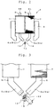
- a moving-magnet type pickup cartridge according to the first embodiment of the invention will be described below with reference to FIGS. 1 to 4 .
- the moving-magnet type pickup cartridge includes a holder 2 that is attached to the front side of a body 1 with a bolt 3 screwed into the body 1.
- the holder 2 is bent in an L-shape having a slightly obtuse angle.
- a magnetic circuit 4 including yokes and the like is attached to the holder 2 in a slightly downward direction to correspond to an inclination angle of a front end surface of the holder 2.
- a pair of left-channel and right-channel magnetic circuits 4L and 4R are provided to reproduce signals from a 45-45 system stereo phonograph record.
- the inner wall and the outer wall of a sound groove on a phonograph record have an inclination of 45 degrees each from the normal, and a left-channel sound and a right-channel sound are independently recorded, respectively.
- left-channel and right-channel magnetic circuits 4L and 4R have the same configuration, and hereinafter the description will be given as to one of the magnetic circuits and a redundant description regarding the other component will be omitted.
- FIG. 1 shows the left-channel magnetic circuit 4L including a yoke 5 formed in a U-shape. Tip ends of both leg parts of the yoke 5 face each other in parallel with a narrowed space between the tip ends, and form a pair of magnetic poles 5a and 5b. The pair of magnetic poles face a magnet provided on a cantilever that will be described later.
- Both leg parts of the yoke 5 bent in a U-shape have generating coils 7 being wounded thereon to bobbins 6 respectively.
- the two generating coils 7 are connected in series to output a signal.
- An added signal from the generating coils 7 connected in series is output to terminal pins 9a and 9b implanted in a terminal plate 8 attached to the rear end of the body 1.
- a vibration unit 11 including a cantilever is also attached to the body 1 by utilizing a thick portion at the lower end of the body 1.
- the vibration unit 11 includes a cantilever 12, a stylus chip 13 attached downward to a front end part in the longitudinal direction of the cantilever 12, a damper 14 that is provided at a base end part in the longitudinal direction of the cantilever 12 and supports the cantilever 12 in a swingable manner, and the like.
- the cantilever 12 is pulled by wire (not illustrated) enclosed in a stopper pin 15 toward the damper 14 formed in a doughnut shape.
- the cantilever 12 is supported in a swingable manner with respect to the body 1 by using flexibility of the damper.
- the stopper pin 15 is accommodated in a shaft hole formed on the body 1, and is supported by a bolt 16 that is screwed on the body 1 toward the shaft hole.
- a bar-shaped magnet 18 is attached along the longitudinal direction of the cantilever 12 and immediately above the stylus chip 13 that is provided at the front end part of the cantilever 12.
- the magnet 18 is magnetized such that one end in the axial direction is the N-pole, and the other end is the S-pole.
- Each of the magnetic poles 5a and 5b of the yoke 5 is disposed to face either end of the magnet 18 magnetized in the axial direction.
- the pair of left and right yokes 5 are disposed above the cantilever 12 with the cantilever 12 being centered between the yokes as shown in FIG. 3 .
- the magnetic poles 5a and 5b of both leg parts of each of the yokes 5 are disposed to face each other in the directions of the axes of maximum sensitivity of the 45-45 system with respect to the magnet 18.
- FIG. 3 illustrates a state in which the magnet 18 is vibrated by the sound groove of the left-channel of the phonograph record.
- the amplitude La of motion of the magnet 18 causes to increase or to decrease the magnetic flux with respect to the yoke 5 of the left-channel (yoke on the right side in FIG. 3 ).
- This configuration allows to provide the terminal pins 9a and 9b of the left-channel with sound output depending on the change in the magnetic flux.
- the above-described vibration movement of the magnet 18 does not change the distance of the magnet from the magnetic pole with respect to the yoke 5 of the right-channel. Accordingly, the sound output is not generated at the terminal pins 9a and 9b of the right-channel, and thus the left and right channels can be sufficiently separated.
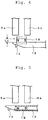
- FIG. 5 shows a moving-magnet type pickup cartridge according to the second embodiment of the invention.
- a bar-shaped magnet 18 is accommodated in the front end part of the cantilever 12 immediately behind the stylus chip 13.
- the magnet 18 accommodated in the cantilever 12 is also magnetized in the axial direction, and each of the magnetic poles 5a and 5b of the yoke 5 faces either end of the magnet 18 magnetized in the axial direction.
- the yokes 5 each of which includes the generating coils 7 forming the left or right channel can be disposed above the cantilever 12 that accommodates the magnet 18 in the cantilever 12 being centered between the yokes 5.
- a moving-magnet type stereo pickup cartridge can be provided like in the first embodiment.
- the magnet is configured to vibrate in a state in which the magnet is directly connected to the vibrating stylus chip that follows a sound groove of a phonograph record.
- This configuration enables to transfer a change in the magnetic flux density caused by a large vibration movement of the magnet to the yokes, and thus a moving-magnet type pickup cartridge having a high generation efficiency can be provided.
- the magnet vibrates in a state in which the magnet is directly connected to the vibrating stylus chip, it is possible to exhibit the advantageous effects as described in Summary of the Invention. For example, delay in a signal due to interposition of the cantilever and distortion due to bending of the cantilever can be suppressed.
Landscapes
- Physics & Mathematics (AREA)
- Engineering & Computer Science (AREA)
- Electromagnetism (AREA)
- Acoustics & Sound (AREA)
- Signal Processing (AREA)
- Power Engineering (AREA)
- Moving Of Heads (AREA)
- Reciprocating, Oscillating Or Vibrating Motors (AREA)
Applications Claiming Priority (1)
| Application Number | Priority Date | Filing Date | Title |
|---|---|---|---|
| JP2015086465A JP6616095B2 (ja) | 2015-04-21 | 2015-04-21 | 可動マグネット型ピックアップカートリッジ |
Publications (2)
| Publication Number | Publication Date |
|---|---|
| EP3086571A1 true EP3086571A1 (de) | 2016-10-26 |
| EP3086571B1 EP3086571B1 (de) | 2018-08-01 |
Family
ID=55802248
Family Applications (1)
| Application Number | Title | Priority Date | Filing Date |
|---|---|---|---|
| EP16165844.8A Active EP3086571B1 (de) | 2015-04-21 | 2016-04-18 | Tonabnehmer mit bewegtem magnet |
Country Status (4)
| Country | Link |
|---|---|
| US (1) | US9659580B2 (de) |
| EP (1) | EP3086571B1 (de) |
| JP (1) | JP6616095B2 (de) |
| CN (1) | CN106067718A (de) |
Citations (2)
| Publication number | Priority date | Publication date | Assignee | Title |
|---|---|---|---|---|
| GB884335A (en) * | 1958-02-27 | 1961-12-13 | Gen Electric | Improvements in stereophonic phonograph pickups |
| EP0555497A1 (de) * | 1992-02-11 | 1993-08-18 | Hiroshi Hamamura | Hebelarmsdämpfungssystem und Tonabnehmer |
Family Cites Families (9)
| Publication number | Priority date | Publication date | Assignee | Title |
|---|---|---|---|---|
| JPS4965202A (de) * | 1972-10-20 | 1974-06-25 | ||
| JPS5121802A (en) * | 1974-08-13 | 1976-02-21 | Matsushita Electric Industrial Co Ltd | Kadojishakugatapitsukuatsupukaatoritsuji |
| JPS542101A (en) | 1977-06-07 | 1979-01-09 | Sansui Electric Co | Pickup cartridge |
| JPS545401U (de) * | 1977-06-14 | 1979-01-13 | ||
| JPS5414202A (en) * | 1977-07-05 | 1979-02-02 | Ogura Jewel Industry Co Ltd | Moving magnet pickup cartridge |
| JPS55121798A (en) | 1979-03-14 | 1980-09-19 | Matsushita Electric Ind Co Ltd | Movable magnet type pickup cartridge |
| FR2640828A1 (fr) * | 1988-07-21 | 1990-06-22 | Seiko Epson Corp | Actionneur electromagnetique |
| EP2020502A1 (de) * | 2007-08-01 | 2009-02-04 | Prüfrex-Elektro-Apparatebau | Elektrisches Zündverfahren für Brennkraftmaschinen |
| US9313306B2 (en) * | 2010-12-27 | 2016-04-12 | Rohm Co., Ltd. | Mobile telephone cartilage conduction unit for making contact with the ear cartilage |
-
2015
- 2015-04-21 JP JP2015086465A patent/JP6616095B2/ja active Active
-
2016
- 2016-04-12 US US15/096,912 patent/US9659580B2/en not_active Expired - Fee Related
- 2016-04-18 EP EP16165844.8A patent/EP3086571B1/de active Active
- 2016-04-21 CN CN201610252483.3A patent/CN106067718A/zh not_active Withdrawn
Patent Citations (2)
| Publication number | Priority date | Publication date | Assignee | Title |
|---|---|---|---|---|
| GB884335A (en) * | 1958-02-27 | 1961-12-13 | Gen Electric | Improvements in stereophonic phonograph pickups |
| EP0555497A1 (de) * | 1992-02-11 | 1993-08-18 | Hiroshi Hamamura | Hebelarmsdämpfungssystem und Tonabnehmer |
Also Published As
| Publication number | Publication date |
|---|---|
| JP6616095B2 (ja) | 2019-12-04 |
| JP2016208213A (ja) | 2016-12-08 |
| EP3086571B1 (de) | 2018-08-01 |
| CN106067718A (zh) | 2016-11-02 |
| US9659580B2 (en) | 2017-05-23 |
| US20160314806A1 (en) | 2016-10-27 |
Similar Documents
| Publication | Publication Date | Title |
|---|---|---|
| US11070119B2 (en) | Manufacturing method of vibrating actuator | |
| US8649550B2 (en) | Multi-magnet system and speaker using same | |
| DK152477B (da) | Elektrodynamisk transducer til omsaetning af mekaniske svingninger til elektriske signaler eller omvendt, samt stereofonisk og monofonisk pickuphoved og elektrodynamisk mikrofon med en saadan transducer. | |
| CN208638639U (zh) | 扬声器 | |
| CN105744450B (zh) | 动圈式立体声拾音头 | |
| US2875282A (en) | Binaural phonograph pickup | |
| US3077522A (en) | Stereophonic pickup cartridge | |
| US9659580B2 (en) | Moving-magnet type pickup cartridge | |
| JP2010263362A (ja) | スピーカー | |
| US2553492A (en) | Magnetic pickup having multistyli | |
| US3627931A (en) | Moving magnet type stereo pickup | |
| US3230318A (en) | Transducer | |
| US3463889A (en) | Moving magnet stereophonic pickup | |
| US3729596A (en) | Electrodynamic sound pickup or sound-track cutting device | |
| CA1054527A (en) | Electrodynamic transducer with annular gap in flux path | |
| CA1139233A (en) | Moving coil type stereophonic pickup cartridge | |
| JP2013070138A (ja) | ヘッドホン装置 | |
| US4630253A (en) | Electromagnetic pickup cartridge having elongate core elements | |
| JP2020027993A (ja) | ムービングコイル型モノラルレコード再生カートリッジ | |
| US4238646A (en) | Pickup cartridge for reproducing signals recorded on a 45--45 stereophonic record disk | |
| US9420377B2 (en) | Audio playback device | |
| CN214154834U (zh) | 喇叭 | |
| US1724360A (en) | Transmitter | |
| JPS5929437Y2 (ja) | ム−ビングコイル形ピツクアツプカ−トリツジ | |
| USRE29232E (en) | Magnetic stereophonic phonograph pickup |
Legal Events
| Date | Code | Title | Description |
|---|---|---|---|
| PUAI | Public reference made under article 153(3) epc to a published international application that has entered the european phase |
Free format text: ORIGINAL CODE: 0009012 |
|
| AK | Designated contracting states |
Kind code of ref document: A1 Designated state(s): AL AT BE BG CH CY CZ DE DK EE ES FI FR GB GR HR HU IE IS IT LI LT LU LV MC MK MT NL NO PL PT RO RS SE SI SK SM TR |
|
| AX | Request for extension of the european patent |
Extension state: BA ME |
|
| STAA | Information on the status of an ep patent application or granted ep patent |
Free format text: STATUS: REQUEST FOR EXAMINATION WAS MADE |
|
| 17P | Request for examination filed |
Effective date: 20170405 |
|
| RBV | Designated contracting states (corrected) |
Designated state(s): AL AT BE BG CH CY CZ DE DK EE ES FI FR GB GR HR HU IE IS IT LI LT LU LV MC MK MT NL NO PL PT RO RS SE SI SK SM TR |
|
| GRAP | Despatch of communication of intention to grant a patent |
Free format text: ORIGINAL CODE: EPIDOSNIGR1 |
|
| STAA | Information on the status of an ep patent application or granted ep patent |
Free format text: STATUS: GRANT OF PATENT IS INTENDED |
|
| RIC1 | Information provided on ipc code assigned before grant |
Ipc: H04R 11/12 20060101AFI20180201BHEP |
|
| INTG | Intention to grant announced |
Effective date: 20180306 |
|
| RIN1 | Information on inventor provided before grant (corrected) |
Inventor name: MIYATA, MITSUO |
|
| GRAS | Grant fee paid |
Free format text: ORIGINAL CODE: EPIDOSNIGR3 |
|
| GRAA | (expected) grant |
Free format text: ORIGINAL CODE: 0009210 |
|
| STAA | Information on the status of an ep patent application or granted ep patent |
Free format text: STATUS: THE PATENT HAS BEEN GRANTED |
|
| AK | Designated contracting states |
Kind code of ref document: B1 Designated state(s): AL AT BE BG CH CY CZ DE DK EE ES FI FR GB GR HR HU IE IS IT LI LT LU LV MC MK MT NL NO PL PT RO RS SE SI SK SM TR |
|
| REG | Reference to a national code |
Ref country code: GB Ref legal event code: FG4D |
|
| REG | Reference to a national code |
Ref country code: CH Ref legal event code: EP Ref country code: AT Ref legal event code: REF Ref document number: 1025768 Country of ref document: AT Kind code of ref document: T Effective date: 20180815 |
|
| REG | Reference to a national code |
Ref country code: IE Ref legal event code: FG4D |
|
| REG | Reference to a national code |
Ref country code: DE Ref legal event code: R096 Ref document number: 602016004391 Country of ref document: DE |
|
| REG | Reference to a national code |
Ref country code: NL Ref legal event code: MP Effective date: 20180801 |
|
| REG | Reference to a national code |
Ref country code: LT Ref legal event code: MG4D |
|
| REG | Reference to a national code |
Ref country code: AT Ref legal event code: MK05 Ref document number: 1025768 Country of ref document: AT Kind code of ref document: T Effective date: 20180801 |
|
| PG25 | Lapsed in a contracting state [announced via postgrant information from national office to epo] |
Ref country code: AT Free format text: LAPSE BECAUSE OF FAILURE TO SUBMIT A TRANSLATION OF THE DESCRIPTION OR TO PAY THE FEE WITHIN THE PRESCRIBED TIME-LIMIT Effective date: 20180801 Ref country code: FI Free format text: LAPSE BECAUSE OF FAILURE TO SUBMIT A TRANSLATION OF THE DESCRIPTION OR TO PAY THE FEE WITHIN THE PRESCRIBED TIME-LIMIT Effective date: 20180801 Ref country code: RS Free format text: LAPSE BECAUSE OF FAILURE TO SUBMIT A TRANSLATION OF THE DESCRIPTION OR TO PAY THE FEE WITHIN THE PRESCRIBED TIME-LIMIT Effective date: 20180801 Ref country code: IS Free format text: LAPSE BECAUSE OF FAILURE TO SUBMIT A TRANSLATION OF THE DESCRIPTION OR TO PAY THE FEE WITHIN THE PRESCRIBED TIME-LIMIT Effective date: 20181201 Ref country code: NO Free format text: LAPSE BECAUSE OF FAILURE TO SUBMIT A TRANSLATION OF THE DESCRIPTION OR TO PAY THE FEE WITHIN THE PRESCRIBED TIME-LIMIT Effective date: 20181101 Ref country code: GR Free format text: LAPSE BECAUSE OF FAILURE TO SUBMIT A TRANSLATION OF THE DESCRIPTION OR TO PAY THE FEE WITHIN THE PRESCRIBED TIME-LIMIT Effective date: 20181102 Ref country code: LT Free format text: LAPSE BECAUSE OF FAILURE TO SUBMIT A TRANSLATION OF THE DESCRIPTION OR TO PAY THE FEE WITHIN THE PRESCRIBED TIME-LIMIT Effective date: 20180801 Ref country code: NL Free format text: LAPSE BECAUSE OF FAILURE TO SUBMIT A TRANSLATION OF THE DESCRIPTION OR TO PAY THE FEE WITHIN THE PRESCRIBED TIME-LIMIT Effective date: 20180801 Ref country code: SE Free format text: LAPSE BECAUSE OF FAILURE TO SUBMIT A TRANSLATION OF THE DESCRIPTION OR TO PAY THE FEE WITHIN THE PRESCRIBED TIME-LIMIT Effective date: 20180801 Ref country code: BG Free format text: LAPSE BECAUSE OF FAILURE TO SUBMIT A TRANSLATION OF THE DESCRIPTION OR TO PAY THE FEE WITHIN THE PRESCRIBED TIME-LIMIT Effective date: 20181101 Ref country code: PL Free format text: LAPSE BECAUSE OF FAILURE TO SUBMIT A TRANSLATION OF THE DESCRIPTION OR TO PAY THE FEE WITHIN THE PRESCRIBED TIME-LIMIT Effective date: 20180801 |
|
| PG25 | Lapsed in a contracting state [announced via postgrant information from national office to epo] |
Ref country code: LV Free format text: LAPSE BECAUSE OF FAILURE TO SUBMIT A TRANSLATION OF THE DESCRIPTION OR TO PAY THE FEE WITHIN THE PRESCRIBED TIME-LIMIT Effective date: 20180801 Ref country code: AL Free format text: LAPSE BECAUSE OF FAILURE TO SUBMIT A TRANSLATION OF THE DESCRIPTION OR TO PAY THE FEE WITHIN THE PRESCRIBED TIME-LIMIT Effective date: 20180801 Ref country code: HR Free format text: LAPSE BECAUSE OF FAILURE TO SUBMIT A TRANSLATION OF THE DESCRIPTION OR TO PAY THE FEE WITHIN THE PRESCRIBED TIME-LIMIT Effective date: 20180801 |
|
| PG25 | Lapsed in a contracting state [announced via postgrant information from national office to epo] |
Ref country code: ES Free format text: LAPSE BECAUSE OF FAILURE TO SUBMIT A TRANSLATION OF THE DESCRIPTION OR TO PAY THE FEE WITHIN THE PRESCRIBED TIME-LIMIT Effective date: 20180801 Ref country code: RO Free format text: LAPSE BECAUSE OF FAILURE TO SUBMIT A TRANSLATION OF THE DESCRIPTION OR TO PAY THE FEE WITHIN THE PRESCRIBED TIME-LIMIT Effective date: 20180801 Ref country code: CZ Free format text: LAPSE BECAUSE OF FAILURE TO SUBMIT A TRANSLATION OF THE DESCRIPTION OR TO PAY THE FEE WITHIN THE PRESCRIBED TIME-LIMIT Effective date: 20180801 Ref country code: IT Free format text: LAPSE BECAUSE OF FAILURE TO SUBMIT A TRANSLATION OF THE DESCRIPTION OR TO PAY THE FEE WITHIN THE PRESCRIBED TIME-LIMIT Effective date: 20180801 Ref country code: EE Free format text: LAPSE BECAUSE OF FAILURE TO SUBMIT A TRANSLATION OF THE DESCRIPTION OR TO PAY THE FEE WITHIN THE PRESCRIBED TIME-LIMIT Effective date: 20180801 |
|
| REG | Reference to a national code |
Ref country code: DE Ref legal event code: R097 Ref document number: 602016004391 Country of ref document: DE |
|
| PG25 | Lapsed in a contracting state [announced via postgrant information from national office to epo] |
Ref country code: SK Free format text: LAPSE BECAUSE OF FAILURE TO SUBMIT A TRANSLATION OF THE DESCRIPTION OR TO PAY THE FEE WITHIN THE PRESCRIBED TIME-LIMIT Effective date: 20180801 Ref country code: DK Free format text: LAPSE BECAUSE OF FAILURE TO SUBMIT A TRANSLATION OF THE DESCRIPTION OR TO PAY THE FEE WITHIN THE PRESCRIBED TIME-LIMIT Effective date: 20180801 Ref country code: SM Free format text: LAPSE BECAUSE OF FAILURE TO SUBMIT A TRANSLATION OF THE DESCRIPTION OR TO PAY THE FEE WITHIN THE PRESCRIBED TIME-LIMIT Effective date: 20180801 |
|
| PLBE | No opposition filed within time limit |
Free format text: ORIGINAL CODE: 0009261 |
|
| STAA | Information on the status of an ep patent application or granted ep patent |
Free format text: STATUS: NO OPPOSITION FILED WITHIN TIME LIMIT |
|
| 26N | No opposition filed |
Effective date: 20190503 |
|
| PG25 | Lapsed in a contracting state [announced via postgrant information from national office to epo] |
Ref country code: SI Free format text: LAPSE BECAUSE OF FAILURE TO SUBMIT A TRANSLATION OF THE DESCRIPTION OR TO PAY THE FEE WITHIN THE PRESCRIBED TIME-LIMIT Effective date: 20180801 |
|
| REG | Reference to a national code |
Ref country code: CH Ref legal event code: PL |
|
| REG | Reference to a national code |
Ref country code: BE Ref legal event code: MM Effective date: 20190430 |
|
| PG25 | Lapsed in a contracting state [announced via postgrant information from national office to epo] |
Ref country code: MC Free format text: LAPSE BECAUSE OF FAILURE TO SUBMIT A TRANSLATION OF THE DESCRIPTION OR TO PAY THE FEE WITHIN THE PRESCRIBED TIME-LIMIT Effective date: 20180801 Ref country code: LU Free format text: LAPSE BECAUSE OF NON-PAYMENT OF DUE FEES Effective date: 20190418 |
|
| PG25 | Lapsed in a contracting state [announced via postgrant information from national office to epo] |
Ref country code: CH Free format text: LAPSE BECAUSE OF NON-PAYMENT OF DUE FEES Effective date: 20190430 Ref country code: LI Free format text: LAPSE BECAUSE OF NON-PAYMENT OF DUE FEES Effective date: 20190430 |
|
| PG25 | Lapsed in a contracting state [announced via postgrant information from national office to epo] |
Ref country code: BE Free format text: LAPSE BECAUSE OF NON-PAYMENT OF DUE FEES Effective date: 20190430 |
|
| PG25 | Lapsed in a contracting state [announced via postgrant information from national office to epo] |
Ref country code: TR Free format text: LAPSE BECAUSE OF FAILURE TO SUBMIT A TRANSLATION OF THE DESCRIPTION OR TO PAY THE FEE WITHIN THE PRESCRIBED TIME-LIMIT Effective date: 20180801 |
|
| PG25 | Lapsed in a contracting state [announced via postgrant information from national office to epo] |
Ref country code: IE Free format text: LAPSE BECAUSE OF NON-PAYMENT OF DUE FEES Effective date: 20190418 |
|
| PG25 | Lapsed in a contracting state [announced via postgrant information from national office to epo] |
Ref country code: PT Free format text: LAPSE BECAUSE OF FAILURE TO SUBMIT A TRANSLATION OF THE DESCRIPTION OR TO PAY THE FEE WITHIN THE PRESCRIBED TIME-LIMIT Effective date: 20181201 |
|
| PG25 | Lapsed in a contracting state [announced via postgrant information from national office to epo] |
Ref country code: CY Free format text: LAPSE BECAUSE OF FAILURE TO SUBMIT A TRANSLATION OF THE DESCRIPTION OR TO PAY THE FEE WITHIN THE PRESCRIBED TIME-LIMIT Effective date: 20180801 |
|
| PG25 | Lapsed in a contracting state [announced via postgrant information from national office to epo] |
Ref country code: HU Free format text: LAPSE BECAUSE OF FAILURE TO SUBMIT A TRANSLATION OF THE DESCRIPTION OR TO PAY THE FEE WITHIN THE PRESCRIBED TIME-LIMIT; INVALID AB INITIO Effective date: 20160418 Ref country code: MT Free format text: LAPSE BECAUSE OF FAILURE TO SUBMIT A TRANSLATION OF THE DESCRIPTION OR TO PAY THE FEE WITHIN THE PRESCRIBED TIME-LIMIT Effective date: 20180801 |
|
| PG25 | Lapsed in a contracting state [announced via postgrant information from national office to epo] |
Ref country code: MK Free format text: LAPSE BECAUSE OF FAILURE TO SUBMIT A TRANSLATION OF THE DESCRIPTION OR TO PAY THE FEE WITHIN THE PRESCRIBED TIME-LIMIT Effective date: 20180801 |
|
| PGFP | Annual fee paid to national office [announced via postgrant information from national office to epo] |
Ref country code: DE Payment date: 20250430 Year of fee payment: 10 |
|
| PGFP | Annual fee paid to national office [announced via postgrant information from national office to epo] |
Ref country code: FR Payment date: 20250410 Year of fee payment: 10 |
|
| PGFP | Annual fee paid to national office [announced via postgrant information from national office to epo] |
Ref country code: GB Payment date: 20260311 Year of fee payment: 11 |